JP2004017896A - Track frame for crawler vehicle - Google Patents
Track frame for crawler vehicle Download PDFInfo
- Publication number
- JP2004017896A JP2004017896A JP2002178863A JP2002178863A JP2004017896A JP 2004017896 A JP2004017896 A JP 2004017896A JP 2002178863 A JP2002178863 A JP 2002178863A JP 2002178863 A JP2002178863 A JP 2002178863A JP 2004017896 A JP2004017896 A JP 2004017896A
- Authority
- JP
- Japan
- Prior art keywords
- track frame
- track
- attachment
- mounting
- frame
- Prior art date
- Legal status (The legal status is an assumption and is not a legal conclusion. Google has not performed a legal analysis and makes no representation as to the accuracy of the status listed.)
- Pending
Links
Images


Abstract
Description
【0001】
【発明の属する技術分野】
本発明はブルドーザや油圧ショベル等の建設・土木機械等の履帯型車両におけるトラックフレームに係わり、特に、トラックフレームの上面に固着して堆積する土砂等の除去作業を容易に且つ確実に行うことが可能な履帯型車両のトラックフレームに関する。
【0002】
【従来の技術】
従来から、ブルドーザや油圧ショベル等の建設・土木機械等の履帯型車両における足まわり装置は、湿地、或いは土砂、砂利、砕石等の硬軟質地盤や、その急勾配の硬軟質地盤等を走行するために使用される。この種のブルドーザの足まわり装置の一例を図6及び図7に示す。これらの図において、この従来の足まわり装置1は図示せぬ車体の左右両側ともに同一構造を有しているため、片側の足まわり装置1のみを示している。
【0003】
この従来の足まわり装置1は、図示せぬ車体の下部にイコライザバー2等を介して取着されたトラックフレーム3を備えている。同トラックフレーム3は下方に開放端を有する略逆コ字状をなすハウジング構造とされている。このトラックフレーム3は、図示せぬ車体の後部に配されたスプロケット(起動輪)4、前部に配されたアイドラ(遊動輪)5、中間部の上面に配された前後一対のキャリアローラ(上部転輪)6,6、及び同中間部の前後にわたって内部に配された複数のトラックローラ(下部転輪)7,…,7からなる走行輪が設けられている。これらの走行輪には走行用履帯8が回動可能に掛け廻されている。同履帯8は、図示せぬ地盤接地用の複数の履板を同じく図示を省略した無端状のリンクチェーンにボルト止めすることにより構成されている。
【0004】
かかるブルドーザの稼働中に、水分を含んだ土砂や砕石等(以下、泥土等という。)が前記履帯8により巻き上げられ、前記トラックローラ7の上方から前記トラックフレーム3の内部へ侵入する。泥土等が前記トラックフレーム3内に侵入し続けると、同トラックフレーム3内に泥土等が固着し、次第に堆積する。その結果、前記トラックローラ7は前記トラックフレーム3内に固着堆積した泥土等の塊と激しく干渉し、前記トラックローラ7が変形、磨滅又は破損するという問題などがある。
【0005】
かかる不具合を解消すべく、例えば本出願人が先に提案した特開平9−156545号公報には、トラックフレーム内への泥土等の侵入を防止する履帯型トラクタの足まわり装置の一例が開示されている。同公報に開示された足まわり装置は、下方に開放端を有する略逆コ字状をなすトラックフレームの内部と、離型剤が塗布されたトラックローラとの間に形成された空間部に、常温又は所定の温度で硬化する発砲充填材を充填している。
【0006】
かかる構成により、前記トラックローラ等の走行輪に回動可能に掛け廻された履帯により巻き上げられる泥土等が、トラックフレームの略コ字状の開放端から同フレーム内へ侵入することを阻止している。これにより、前記履帯により巻き上げられる泥土等はトラックフレームの下方へ排出されるため、前記トラックローラの早期の磨耗やトラックフレームの変形等を防止することができるものである。
【0007】
【発明が解決しようとする課題】
上述のごとき従来の履帯型車両の足まわり装置は、一般にトラックフレームに回動可能に支持されたキャリアローラ(上部転輪)やトラックローラ(下部転輪)等の走行輪に無端状の履帯を回動可能に掛け廻している。このため、回動する履帯により巻き上げられる泥土等は、既述したごとく前記トラックフレームの略コ字状の開放端から同フレーム内へ侵入するだけではない。
【0008】
前記トラックフレーム内へ侵入することなく巻き上げられる泥土等は、前記トラックフレームの上方へ向けて運ばれたのち、前記キャリアローラの上方から前記トラックフレームの上面へ向けて落下し、同トラックフレームの上面に固着して堆積する。更には、作業中の各種作業機から落下する泥土等もトラックフレームの上面に堆積する。前記トラックフレームの上面に泥土等の塊が大量に堆積すると、足まわり装置の重量が増加するため、走行性や作業操作性などが極めて悪化する。その結果、オペレータの運転感覚の不良を起こすだけではなく、作業感覚などが損なわれやすい。
【0009】
前記足まわり装置は過酷な条件下で使用されるため、前記トラックローラに変形、磨滅又は破損を生じるだけではなく、前記キャリアローラにも、前記トラックフレームの上面に固着して堆積した泥土等の塊と激しく干渉し、前記キャリアローラに変形、磨滅や破損等が急速に起こり、永い間清掃等をしないと、足まわり装置としての機能が短期間に失われてしまう。その結果、前記キャリアローラは、たびたび交換しなければならなくなる。このため、履帯型車両による作業後に、前記足まわり装置に固着して堆積した泥土等の塊は必ず除去することが肝要である。
【0010】
しかしながら、前記トラックフレームの上面には、前記キャリアローラ及びイコライザバー等の各種の部品を取り付ける取付座部が上方側に向けて膨出している。更には、同取付座部に前記部品を取着する付設部材の取着部が表面に突出すると共に、同取着部を締付固定する複数の取付ボルトの頭部が上方に突出している。このように、前記トラックフレームの上面には、前記取付座部及び取付ボルト頭部などによる凹凸部分が多く混在している。
【0011】
このため、スコップ等を使用してトラックフレームの上面に固着堆積した泥土等を除去しようとしても、同トラックフレーム上の前記凹凸部分に固着堆積した泥土等の塊が大量に残ってしまい、同トラックフレームの上面に固着堆積した泥土等の塊を完全に取り除くことができない。これらの泥土等の除去を完全にするには、前記履帯により巻き上げられた泥土等の除去作業が極めて煩雑となり、極めて手間がかかるため、相当な時間と労力とを必要とする。
【0012】
本発明は、かかる従来の課題を解消すべくなされたものであり、その具体的な目的は、トラックフレームの上面に作業中あるいは走行中にも土砂等が滞留せず、仮に周辺に固着堆積する土砂等を簡単に取り除くことができ、土砂等の除去作業を効率よく且つ確実に行うことが可能なブルドーザや油圧ショベルの建設・土木機械等の履帯型車両におけるトラックフレームを提供することにある。
【0013】
【課題を解決するための手段及び作用効果】
本件請求項1に係る発明は、イコライザバー、キャリアローラ、蓋体等の各種の付設部材が取着された履帯型車両のトラックフレームであって、同付設部材が、前記トラックフレームの表面の一部に嵌着固定される取着部を有し、同取着部の表面と前記トラックフレームの表面とが略面一とされてなることを特徴とする履帯型車両のトラックフレームにある。
【0014】
本発明の基本的な履帯型車両のトラックフレームは、前記トラックフレームの表面の一部に突出する取付座部や取付ボルト頭部等による複数の凹凸部分を排除している。本発明は、イコライザバーやキャリアローラ(上部転輪)等の各支持部材や蓋体等の各種の付設部材の取着部を前記トラックフレームの表面の一部に嵌め込むことにより、同取着部の表面と前記トラックフレームの表面とを略面一に配している。
【0015】
かかる構成により、回動する走行用履帯により巻き上げられる土砂、砂利や砕石などの泥土等が前記トラックフレームの表面に固着して堆積したとき、例えばスコップ等を使用して前記トラックフレームの表面の泥土等の塊を一挙に取り除くことができるようになる。その結果、泥土等の除去作業を極めて効率よく行うことができると共に、履帯型車両がもつ走行性や作業操作性などの機能を長期間にわたって維持することができる。
【0016】
前記付設部材の取着部の大きさ及び形態は、嵌着固定しようとするトラックフレームの表面の大きさ及び形態によって任意に決定でき、前記付設部材を介して前記トラックフレームの表面に取着すべき前記イコライザバー、キャリアローラ(上部転輪)或いは蓋体等を支持し得るに十分な最小限の大きさ及び形態とすることが可能であり、その設計の自由度が大きい。また、前記トラックフレームに対する付設部材の固着手段として、溶接或いは取付ボルトによる固着が強度の点から望ましいが、他の固着具を採用することもできる。
【0017】
前記付設部材の取着部の形態として、単純な正多角形や円形形状でもよいが、前記トラックフレームの表面に位置決めがしやすく、且つ安定した嵌着固定が可能な形状であることが好ましく、例えば楕円形、正多角形以外の多角形をもつ板体により構成することができる。かかる構成により、前記トラックフレームに対する付設部材の位置決めが容易にできるようになり、前記トラックフレームの車体への組付工数を削減することができる。
【0018】
請求項2に係る発明は、前記トラックフレームが、前記取着部を嵌着する嵌着部と前記取着部を前記フレームの内部側から固定支持するバックアップ部とを有していることを特徴としている。
前記トラックフレームに対する付設部材の固着構造は、前記トラックフレームの表面の一部に設けられた嵌着部に、同嵌着部よりも上方側に突出させることなく前記付設部材の取着部を安定して着座させ、同取着部を前記トラックフレームの内部側から支持するバックアップ部に溶接又はボルト締めにより固着する簡単な構成を採用している。
【0019】
前記トラックフレームの嵌着部として、前記取着部を嵌着する少なくとも上部が開口すると共に、その開口部の底部にバックアップ面を有する構成、すなわちトラックフレームの嵌着部に嵌着孔を形成すると共に、その嵌着孔の内周面から内方に向けて延在させるようにバックアップ部材を別付けにより固設するか、或いは前記トラックフレームから下方に向けて底面を有する凹陥部等を形成する。
【0020】
前記トラックフレーム及び前記バックアップ部は、鋳物又は高剛性の板金材により構成されており、それらの厚さ寸法は嵌着固定しようとする前記付設部材の取着部の大きさ及び形態によって任意に設定できる。しかし、少なくとも嵌着部の深さ寸法は取着部の厚さ寸法を越えてはならない。このようにバックアップ部を設けることにより、前記トラックフレームの表面の一部に取着すべき上記イコライザバー、キャリアローラ(上部転輪)及び蓋体等を支持し得るのに十分な剛性及び取付強度をもって、前記付設部材の取着部をフレームの内部側から確実に支持することができる。
【0021】
請求項3に係る発明は、前記トラックフレームに対する前記取着部の嵌着固定が溶接によりなされていることを特徴としている。
この発明は、前記トラックフレームに対する付設部材の取着部の固着手段として、溶接による固着を採用している。前記付設部材は、前記トラックフレームに固着する以前に、既述のごとく前記トラックフレーム表面の嵌着部に嵌着することにより安定して保持されるため、例えば溶接時に位置決め用治具等を使用して作業する必要がない。このため、複雑な取付精度等が不要であり、前記トラックフレームと車両本体との位置合わせを正確に行う必要がなく、容易に溶接が可能となる。この溶接は、トラックフレームの表面側と上記バックアップ部側とからなされる。勿論、上記嵌着部が底部を有する凹陥部として形成される場合は、トラックフレームの表面側だけの溶接でもよい。
【0022】
請求項4に係る発明は、前記トラックフレームのバックアップ部にボルト取付孔を有し、前記取着部の前記ボルト取付孔と対応する部位の表面側に形成された座ぐり孔と、同座ぐり孔に連通するボルト挿通孔とを有してなり、前記取着部と前記トラックフレームとが、前記各孔を介してボルト締めにより固着されていることを特徴としている。
【0023】
前記トラックフレームに対する付設部材の固着手段としては、取付ボルトによる固着が強度の点及び作業性の面から特に好ましい。この発明の付設部材の固着構造は、前記トラックフレームのボルト取付孔と取着部のボルト頭部を収容する座ぐり孔とを合致させ、各孔を介して取付ボルトのネジ部を前記トラックフレームのボルト取付孔に螺着させることにより、前記取付ボルト頭部を前記付設部材の座ぐり孔内に収容固定する簡単な構成を採用している。ここで、前記トラックフレームのボルト取付孔はトラックフレームのバックアップ部に形成され、同取付孔自体が内ネジを有する場合に限らず、同フレームの内部側に固着されたナットのネジ孔などをも含んでいる。前記座ぐり孔の孔深さは、取付ボルトを締結したとき、そのボルト頭部の上面がトラックフレームの表面と略面一となるように決められる。
【0024】
かかる構成により、従来のごとく前記トラックフレームの表面に前記付設部材の取着部を取付ボルトにより締付固定しても、各ボルト頭部はトラックフレームの表面から外部に突出することがなく、同ボルト頭部の上面と前記トラックフレームの表面とが同一面上に配されるようになり、同トラックフレームの外形形状と違和感なく、凹凸部分が存在しない滑らかなトラックフレームの表面が得られる。このため、上述のごとくスコップ等を使用して前記トラックフレームの表面に固着して堆積した泥土等の塊を簡単に除去することができるようになり、泥土等の除去作業を極めて効率よく行うことができる。
【0025】
【発明の実施の形態】
以下、本発明の好適な実施の形態を添付図面に基づいて具体的に説明する。
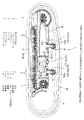
図1は本発明の代表的な実施形態である履帯型車両の足まわり装置の要部を示す構造説明図、図2は図1の矢視A方向からみた矢視図、図3は図1のB−B線の部分断面拡大図、図4は図1のC−C線の部分断面拡大図、図5は図1のD−D線の部分断面拡大図である。なお、これらの図にあって上記従来技術と実質的に同じ部材に関しては、図6及び図7に付した符号と同一の符号を付している。
【0026】
本実施形態では、上記特開平9−156545号公報に記載されたごときブルドーザにおける足まわり装置のトラックフレームを例に挙げて説明するが、本発明はこれに限定されるものではなく、例えば油圧ショベル及びその他の運搬機械等の履帯型車両における足まわり装置にも効果的に使用できる。かかるブルドーザは従来から広く知られた周知の構造を有しているため、ここではその詳しい説明は省略し、本発明の特徴部をなすトラックフレームの構造について具体的に説明する。なお、トラックフレームは図示せぬ車体の左右両側ともに同一構造を有しているため、本実施形態では片側のトラックフレームのみを説明する。
【0027】
図1〜図3において、ブルドーザの足まわり装置1は、図示せぬ車体の下部に配されるトラックフレーム3を備えている。図示例にあっては、このトラックフレーム3は高剛性の鋼鉄材により構成されており、所定の間隔をおいて互いに平行に配された左右一対の側部と、その幅方向の両端側から上方に略円弧面状に膨出した湾曲部(上面)と、同側部の幅方向両端側の下方を閉鎖した閉鎖部とを有するケーシング構造とされている。図示例によるトラックフレーム3は、イコライザバー支持部材10−1を介して図示せぬ車体のイコライザバー2に取着されている。
【0028】
このトラックフレーム3の後部には動力源により駆動するスプロケット4が配されると共に、前部にはアイドラ5が配されている。同トラックフレーム3の上面には、キャリアローラ支持部材10−2を介して取着された前後一対のキャリアローラ6,6が設けられている。同トラックフレーム3の内部には複数のトラックローラ7,…,7が前後にわたって並列に配されている。
【0029】
符号8は車両の走行用履帯を示している。同履帯8は前記スプロケット4、前記アイドラ5、前記キャリアローラ6、及び前記トラックローラ7に回動可能に掛け廻されている。図示せぬ無端状のリンクチェーンには、同じく図示を省略した地面接地用の複数の履板がボルト止めされており、同履板及びリンクチェーンにより履帯8が構成される。
【0030】
上記のごとく構成されたブルドーザの足まわり装置1は、従来から広く知られた周知の構造を有しており、本発明はこれに限定されるものではない。本発明の最も特徴とするところは、ブルドーザ等の履帯型車両の下部に配されるトラックフレーム3の表面の一部にイコライザバー2やキャリアローラ6等の各支持部材10−1,10−2や蓋体10−3の各種の付設部材10の取着部10aを嵌着固定することにより、同取着部10aの表面とトラックフレーム3の表面とを略面一に配することにある。なお、本実施形態ではイコライザバー支持部材10−1、キャリアローラ支持部材10−2や蓋体10−3を総称して付設部材10という。
【0031】
本実施形態では、前記トラックフレーム3の上面には、前記付設部材10の取着部10aを嵌着させる嵌着部11と、同嵌着部11よりも上方側に突出させることなく、同嵌着部11と取着部10aとをトラックフレーム3の内部側から固定支持するバックアップ部であるバックアップ材12とが設けられている。
【0032】
図示例にあっては、前記イコライザバー支持部材10−1は、前記トラックフレーム3の上面の一部に嵌着固定される取着部10aと、同取着部10aの上面から車両内方へ向けて平行に延びる前後一対の取付部10b,10bとを有している。同取付部10bの自由端部はイコライザバー2のピン2aを圧入固定するピン圧入孔が形成されている。各取付部10bはイコライザバー2を挟んで両側に配されており、同イコライザバー2のピン2aに圧入固定されている。
【0033】
前記キャリアローラ支持部材10−2は、前記トラックフレーム3の上面の一部に嵌着固定される取着部10aと、同取着部10aの上面から車両外方に向けて滑らかに湾曲して延びる単一の取付部10bとを有している。同取付部10bの自由端部は前記キャリアローラ6の回動軸を挿入固定する軸孔が形成された取付部10bを有している。同取付部10bは前記キャリアローラ6の回動軸を回動可能に固定支持している。前記イコライザバー支持部材10−1及びキャリアローラ支持部材10−2の各取着部10aは、トラックフレーム3の嵌着部11の内周面と合致した外形形状をなす前後に長い高剛性の鋼鉄板体からなり、各取付部10bは高剛性の鋼鉄柱体からなる。
【0034】
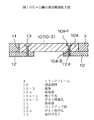
前記イコライザバー支持部材10−1やキャリアローラ支持部材10−2の付設部材10の取着部10aを嵌着固定させる嵌着部11及びバックアップ材12は同一構造を有している。以下の説明は、図4を参照してこれらの部材を説明する。図4において、前記トラックフレーム3の上面の一部には、トラックフレーム3に開口部を有する嵌着部11が形成されている。同嵌着部11は前記付設部材10の取着部10aの厚さと略同一寸法に設定されている。同嵌着部11の底部の開口周辺部には、高剛性の鋼鉄板体からなるバックアップ材12が溶接により固着されている。バックアップ材12は前記取着部10aを支持し得る最小限の大きさをもって形成されている。
【0035】
図示例にあっては、前記バックアップ材12には、複数のボルト取付孔12aが形成されている。前記取着部10aの前記ボルト取付孔12aと対応する部位の表面側には、大径の座ぐり孔10a−1が形成されると共に、同座ぐり孔10a−1に連通する小径のボルト挿通孔10a−2が同心円上に形成されている。前記取着部10aの座ぐり孔10a−1の孔深さは、取付ボルト13を締結したとき、そのボルト頭部の上面がトラックフレーム3の表面と略面一となるように設定されている。
【0036】
前記トラックフレーム3の上面の一部に付設部材10を取着するのにあたっては、前記バックアップ材12のボルト取付孔12aに前記取着部10aの座ぐり孔10a−1及びボルト挿通孔10a−2を合致させ、各孔12a,10a−1,10a−2を介して取付ボルト13のネジ部を前記バックアップ材12のボルト取付孔12aに螺着させることにより、前記取付ボルト13の頭部を前記取着部10aの座ぐり孔10a−1内に収容固定する。
【0037】
かかる構成により、従来のごとくトラックフレームの上面の一部に取着部材の取着部を締付固定する複数のボルト頭部がトラックフレームの上面に突出することはない。前記取付ボルト13の頭部上面がトラックフレーム3の上面と略同一面上に臨んで配されるようになり、同トラックフレーム3の外形形状と違和感なく、凹凸部分が存在しない滑らかなトラックフレーム3の上面が得られる。このため、スコップ等を使用してトラックフレーム3の上面に固着堆積した泥土等の塊を簡単に除去することができ、泥土等の除去作業を極めて効率的に行うことができる。なお、上記実施形態では、前記バックアップ材12自体に内ネジ部をもつボルト取付孔12aを有する構成になっているが、本発明はこれに限定されるものではなく、例えばバックアップ材12の内部側に固着されたナットのネジ孔等であってもよいことは勿論である。
【0038】
上記のごとく構成された付設部材10は図示例に限定されるものではない。同付設部材10の大きさ及び形態は、前記トラックフレーム3の上面の大きさ及び形態によって任意に決定できることは勿論である。また、前記付設部材10は、前記トラックフレーム3の上面に取着すべき前記イコライザバー2、キャリアローラ6を支持し得るに十分な最小限の大きさ及び形態とすることができる。このため、前記付設部材10の設計の自由度は大きい。
【0039】
前記付設部材10の取着部10aの形態として、トラックフレーム3の上面に位置決めがしやすく安定した嵌着固定が可能な形状であることが好ましい。本実施形態では、前記取着部10aは、上述のごとく前後に長い直方板状をなしているが、例えば楕円形、正多角形以外の多角形をもつ高剛性の鋼鉄板体により構成することができる。また、前記取着部10aの底面に前記バックアップ材12の嵌着部11内に挿入し得る突出部を形成することにより、トラックフレーム3の上面に嵌着固定することもできる。かかる構成により、トラックフレーム3に対する付設部材10の位置決めを容易に行うことができると共に、トラックフレーム3の車体への組付工数を軽減することができる。
【0040】
また、前記トラックフレーム3のバックアップ材12にあっても、図示例に限定されるものではない。前記バックアップ材12の大きさ及び形態は、前記付設部材10の取着部10aの表面をトラックフレーム3よりも上方側に突出させることなく安定して着座し得る大きさ及び形態であればよく、例えばトラックフレーム3から下方に向けて底面を有する凹陥部などを使用することもできる。
【0041】
本発明にあっては、前記付設部材10の取着部10aをトラックフレーム3の上面の一部と略面一に配することだけではない。本実施形態では、図1及び図2に示す蓋体10−3の表面が、図5に示すようにトラックフレーム3の上面の一部と略面一に配されている。この蓋体10−3は高剛性の鋼鉄板材からなり、同蓋体10−3の周縁がトラックフレーム3の上面の一部に嵌着固定される取着部10aとされている。同蓋体10−3の取着部10aの表面は、上記各付設部材10と同様にトラックフレーム3の嵌着部11から上方側に突出することなく保持されており、同蓋体10−3を前記バックアップ材12に取付ボルト13にて締付固定している。取付ボルト13の頭部は、前記蓋体10−3に形成された座ぐり孔内に収容固定されており、トラックフレーム3の上面と略面一になるようにして螺着されている。
【0042】
かかる構成により、上述のごとくスコップ等を使用してトラックフレーム3の上面に固着して堆積した泥土等の塊を簡単に除去することができる。なお、前記蓋体10−3の形態は図示例に限定されるものではなく、例えば上記各付設部材10の取着部10aと同様に、前記蓋体10−3の下部にバックアップ材12の開口部内に挿入し得る突出部を有するものであってもよいことは勿論である。
【0043】
上記実施形態によると、トラックフレーム3及びバックアップ材12は高剛性の鋼鉄板体からなるが、本発明にあっては鋳物により構成されていてもよい。それらの厚さ寸法は付設部材10の取着部10aの大きさ及び形態によって任意に設定できるが、前記嵌着部11の深さは前記取着部10aの厚さと略同一寸法に設定することが好ましい。
【0044】
本実施形態では、前記取着部10aの底部とバックアップ材12との間にシーリング材等を介在させることにより、前記嵌着部11の深さ、前記取着部10aやバックアップ材12の各接合部分の形状を安定して確保することができる。このため、前記トラックフレーム3の嵌着部11及び付設部材10の厳格な加工精度を必要とせず、設計の自由度が大きい。前記トラックフレーム3の内部にバックアップ面を設けることにより、同トラックフレーム3の上面に取着すべきイコライザバー2、キャリアローラ6や蓋体10−3等を支持し得るのに十分な剛性及び取付強度をもって、前記付設部材10の取着部10aを前記トラックフレーム3の内部側から確実に支持することができる。
【0045】
前記トラックフレーム3に対する付設部材10の固着手段として、上記実施形態のごとく取付ボルト13による固着が強度の点から望ましいが、溶接或いは他の固着具を採用することもできる。前記付設部材10の取着部10aをトラックフレーム3に溶接して固着する場合には、前記付設部材10は、トラックフレーム3に固着する以前に、既述のごとくトラックフレーム上面に嵌着固定することにより安定して保持される。このため、溶接時に位置決め用治具等を使用して作業する必要がなく、複雑な取付精度等が不要であり、トラックフレーム3と車両本体との位置合わせを正確に行う必要もない。なお、前記取着部10aの溶接による固着は、トラックフレーム3の表面側とバックアップ材12側とからなされる。また、上述のごとく嵌着部11が底部を有する凹陥部として形成される場合は、トラックフレーム3の表面側だけを溶接する。
【0046】
以上の説明からも明らかなように、本発明に係る履帯型車両のトラックフレーム3は、同フレーム3の上面に取付座部及び取付ボルト頭部等による複数の凹凸部分を排除して、前記付設部材10の取着部10aをトラックフレーム3の上面に嵌め込むことにより、同トラックフレーム3の上面と略面一に配している。このため、トラックフレーム3の上面の形態にかかわらずトラックフレーム3を平滑面及び/又は滑らかな湾曲面に構成することができる。
【0047】
回動する走行用履帯8により巻き上げられる土砂、砂利や砕石などの泥土等がトラックフレーム3の上面に固着して堆積したとき、例えばスコップ等を使用してトラックフレーム3の上面に固着堆積した泥土等の塊を一挙に取り除くことができるようになる。その結果、泥土等の除去作業を極めて効率よく行うことができると共に、履帯型車両がもつ走行性や作業操作性等の機能を長期間にわたって保証することができる。なお、本発明は上記各実施形態に限定されるものではなく、それらの実施形態から当業者が容易に変更可能な技術的な範囲をも当然に包含するものである。
【図面の簡単な説明】
【図1】本発明の代表的な実施形態である履帯型車両の足まわり装置の要部を示す構造説明図である。
【図2】図1の矢視A方向からみた矢視図である。
【図3】図1のB−B線の部分断面拡大図である。
【図4】図1のC−C線の部分断面拡大図である。
【図5】図1のD−D線の部分断面拡大図である。
【図6】従来の履帯型車両の足まわり装置の要部を示す構造説明図である。
【図7】同足まわり装置の上面を示す構造説明図である。
【符号の説明】
1 足まわり装置
2 イコライザバー
2a ピン
3 トラックフレーム
4 スプロケット
5 アイドラ
6 キャリアローラ
7 トラックローラ
8 履帯
10 付設部材
10−1 イコライザバー支持部材
10−2 キャリアローラ支持部材
10−3 蓋体
10a 取着部
10a−1 座ぐり孔
10a−2 ボルト挿通孔
10b 取付部
11 嵌着部
12 バックアップ材
12a ボルト取付孔
13 取付ボルト[0001]
TECHNICAL FIELD OF THE INVENTION
The present invention relates to a track frame of a crawler type vehicle such as a bulldozer or a hydraulic shovel, such as a construction / civil engineering machine. The invention relates to a track frame of a possible track type vehicle.
[0002]
[Prior art]
BACKGROUND ART Conventionally, undercarriage devices in crawler-type vehicles, such as construction and civil engineering machines such as bulldozers and hydraulic excavators, travel on hard ground such as swamps, earth and sand, gravel, and crushed stones, or steep hard ground. Used for An example of such a bulldozer suspension device is shown in FIGS. In these drawings, since the
[0003]
The
[0004]
During the operation of the bulldozer, soil and sand, crushed stones, and the like (hereinafter, referred to as mud and the like) containing water are wound up by the
[0005]
In order to solve such a problem, for example, Japanese Unexamined Patent Application Publication No. 9-156545 previously proposed by the present applicant discloses an example of a crawler type tractor undercarriage device for preventing intrusion of mud or the like into a track frame. ing. The undercarriage device disclosed in the publication has a substantially inverted U-shaped track frame having an open end below and a space formed between a track roller coated with a release agent, It is filled with a foam filler that cures at room temperature or at a predetermined temperature.
[0006]
With this configuration, it is possible to prevent mud and the like wound up by the crawler belt rotatably looped around the running wheels such as the track rollers from intruding into the frame from the substantially U-shaped open end of the track frame. I have. As a result, the mud and the like rolled up by the crawler belt are discharged to below the track frame, thereby preventing early wear of the track rollers, deformation of the track frame, and the like.
[0007]
[Problems to be solved by the invention]
As described above, the conventional crawler-type vehicle suspension device generally includes an endless crawler belt on a traveling wheel such as a carrier roller (upper wheel) or a track roller (lower wheel) rotatably supported by a track frame. It is rotatably hung. For this reason, mud and the like rolled up by the rotating crawler belt do not only enter the frame from the substantially U-shaped open end of the track frame as described above.
[0008]
Mud or the like that is rolled up without entering the track frame is transported upward from the track frame, and then falls from above the carrier roller toward the upper surface of the track frame, and becomes upper surface of the track frame. It sticks and deposits on Further, mud and the like that fall from various working machines during operation also accumulate on the upper surface of the truck frame. When a large amount of mud or the like is deposited on the upper surface of the truck frame, the weight of the suspension device increases, and the traveling performance and work operability are extremely deteriorated. As a result, not only does the operator's driving sensation become poor, but also the working sensation tends to be impaired.
[0009]
Since the undercarriage device is used under severe conditions, not only the track roller is deformed, worn out or broken, but also the carrier roller, such as mud adhered and deposited on the upper surface of the track frame. The carrier roller violently interferes with the mass, and the carrier roller is rapidly deformed, worn out, broken, and the like. If the carrier roller is not cleaned for a long time, the function as a suspension device is lost in a short time. As a result, the carrier roller has to be replaced frequently. For this reason, it is important to always remove lump such as mud stuck and deposited on the undercarriage device after work by the crawler type vehicle.
[0010]
However, on the upper surface of the track frame, a mounting seat for mounting various components such as the carrier roller and the equalizer bar bulges upward. Further, the attachment portion of the attachment member for attaching the component to the attachment seat portion projects from the surface, and the heads of a plurality of attachment bolts for tightening and fixing the attachment portion project upward. As described above, many irregularities due to the mounting seat portion and the mounting bolt head are mixed on the upper surface of the track frame.
[0011]
For this reason, even if an attempt is made to remove mud or the like stuck and deposited on the upper surface of the track frame using a scoop or the like, a large amount of mud or the like stuck and deposited on the uneven portion on the track frame remains, and the track Lumps such as mud stuck and deposited on the upper surface of the frame cannot be completely removed. In order to completely remove the mud and the like, the work of removing the mud and the like rolled up by the crawler belt becomes extremely complicated and extremely troublesome, and thus requires considerable time and labor.
[0012]
The present invention has been made to solve such a conventional problem, and a specific object of the present invention is to prevent sediment or the like from accumulating on the upper surface of a truck frame during work or running, and temporarily adhere to the periphery. An object of the present invention is to provide a track frame for a crawler-type vehicle such as a bulldozer or a hydraulic shovel construction / civil engineering machine capable of easily removing soil and the like and efficiently and reliably removing the soil and the like.
[0013]
Means for Solving the Problems and Functions and Effects
The invention according to
[0014]
The track frame of the basic crawler type vehicle according to the present invention excludes a plurality of uneven portions due to a mounting seat portion, a mounting bolt head, and the like protruding from a part of the surface of the track frame. According to the present invention, the mounting portions of various supporting members such as an equalizer bar and a carrier roller (upper wheel) and various attached members such as a lid are fitted into a part of the surface of the track frame to thereby perform the mounting. The surface of the section and the surface of the track frame are substantially flush with each other.
[0015]
With this configuration, when mud or the like, such as earth and sand, gravel and crushed stones, which are rolled up by the rotating crawler track, adheres to and accumulates on the surface of the track frame, for example, using a scoop or the like, the mud on the track frame surface Lump can be removed at once. As a result, the work of removing mud and the like can be performed extremely efficiently, and the functions of the crawler-type vehicle, such as travelability and work operability, can be maintained for a long period of time.
[0016]
The size and form of the attachment portion of the attachment member can be arbitrarily determined according to the size and form of the surface of the track frame to be fitted and fixed, and attached to the surface of the track frame via the attachment member. The equalizer bar, the carrier roller (upper wheel), the lid, and the like can be formed in a minimum size and shape sufficient to support the same, and the degree of freedom in design is large. Further, as a means for fixing the additional member to the track frame, it is desirable to fix the member by welding or mounting bolts from the viewpoint of strength, but other fixing tools may be employed.
[0017]
The form of the attachment portion of the attachment member may be a simple regular polygon or a circular shape, but is preferably a shape that can be easily positioned on the surface of the track frame, and that can be stably fitted and fixed, For example, it can be constituted by a plate having a polygon other than an ellipse and a regular polygon. With this configuration, it is possible to easily position the attachment member with respect to the track frame, and it is possible to reduce man-hours for attaching the track frame to the vehicle body.
[0018]
The invention according to
The attachment structure of the attachment member to the track frame stabilizes the attachment portion of the attachment member without protruding upward from the fitting portion provided on a part of the surface of the track frame. And a simple structure is employed in which the mounting portion is fixed to a backup portion which supports the mounting portion from the inside of the track frame by welding or bolting.
[0019]
The fitting portion of the track frame is configured such that at least an upper portion for fitting the fitting portion is open and a backup surface is provided at the bottom of the opening, that is, a fitting hole is formed in the fitting portion of the track frame. At the same time, a backup member is separately fixed so as to extend inward from the inner peripheral surface of the fitting hole, or a concave portion having a bottom surface downward from the track frame is formed. .
[0020]
The track frame and the backup portion are made of a casting or a high-rigidity sheet metal material, and their thickness dimensions are arbitrarily set according to the size and form of the attachment portion of the attachment member to be fitted and fixed. it can. However, at least the depth of the fitting must not exceed the thickness of the fitting. By providing the backup portion in this manner, sufficient rigidity and mounting strength to support the equalizer bar, carrier roller (upper wheel), lid, and the like to be attached to a part of the surface of the track frame are provided. Thus, the attachment portion of the attachment member can be reliably supported from the inside of the frame.
[0021]
The invention according to
The present invention employs fixing by welding as a fixing means of the attaching portion of the additional member to the track frame. Before the attachment member is fixed to the track frame, the attachment member is stably held by being fitted to the fitting portion on the surface of the track frame as described above. For example, a positioning jig or the like is used at the time of welding. No need to work. For this reason, complicated mounting accuracy and the like are not required, and it is not necessary to accurately align the truck frame with the vehicle body, and welding can be easily performed. This welding is performed from the front surface side of the track frame and the backup portion side. Of course, when the fitting portion is formed as a concave portion having a bottom, welding may be performed only on the surface side of the track frame.
[0022]
The invention according to
[0023]
As a means for fixing the additional member to the track frame, fixing with a mounting bolt is particularly preferable in terms of strength and workability. In the fixing structure of the additional member according to the present invention, the bolt mounting hole of the track frame and the counterbore hole for accommodating the bolt head of the mounting portion are aligned with each other, and the screw portion of the mounting bolt is connected to the track frame through each hole. A simple configuration is adopted in which the head of the mounting bolt is housed and fixed in the counterbore hole of the attached member by screwing into the bolt mounting hole. Here, the bolt mounting hole of the track frame is formed in the backup portion of the track frame, and the bolt mounting hole is not limited to the case where the mounting hole itself has an internal thread, but also includes a screw hole of a nut fixed to the inner side of the frame. Contains. The hole depth of the counterbore is determined so that when the mounting bolt is fastened, the upper surface of the bolt head is substantially flush with the surface of the track frame.
[0024]
With this configuration, even if the attachment portion of the attachment member is tightened and fixed to the surface of the track frame with the mounting bolt as in the related art, each bolt head does not protrude from the surface of the track frame to the outside. Since the upper surface of the bolt head and the surface of the track frame are arranged on the same plane, a smooth track frame surface having no irregularities and no irregularities can be obtained without the external shape of the track frame. For this reason, it becomes possible to easily remove the lump such as mud stuck and deposited on the surface of the truck frame using the scoop or the like as described above, and to perform the removal work of the mud etc. very efficiently. Can be.
[0025]
BEST MODE FOR CARRYING OUT THE INVENTION
Hereinafter, preferred embodiments of the present invention will be specifically described with reference to the accompanying drawings.
FIG. 1 is a structural explanatory view showing a main part of a crawler-type vehicle suspension device according to a typical embodiment of the present invention, FIG. 2 is a view taken in the direction of arrow A in FIG. 1, and FIG. 4 is an enlarged partial cross-sectional view taken along line BB, FIG. 4 is an enlarged partial cross-sectional view taken along line CC in FIG. 1, and FIG. 5 is an enlarged partial cross-sectional view taken along line DD in FIG. In these figures, the same reference numerals as those shown in FIGS. 6 and 7 are assigned to members substantially the same as those of the above-mentioned conventional technology.
[0026]
In the present embodiment, a track frame of an undercarriage device in a bulldozer described in Japanese Patent Application Laid-Open No. 9-156545 will be described as an example. However, the present invention is not limited to this. Also, it can be effectively used for an undercarriage device in a crawler type vehicle such as a transport machine. Since such a bulldozer has a well-known structure which has been widely known, its detailed description is omitted here, and the structure of a track frame which is a feature of the present invention will be specifically described. Since the track frames have the same structure on both the left and right sides of the vehicle body (not shown), only one track frame will be described in this embodiment.
[0027]
1 to 3, a
[0028]
A
[0029]
[0030]
The
[0031]
In the present embodiment, a
[0032]
In the illustrated example, the equalizer bar support member 10-1 has a mounting
[0033]
The carrier roller support member 10-2 is attached to and fixed to a part of the upper surface of the
[0034]
The
[0035]
In the illustrated example, the
[0036]
When attaching the
[0037]
With this configuration, unlike the related art, a plurality of bolt heads for fastening and fixing the attaching portion of the attaching member to a part of the upper surface of the track frame do not project from the upper surface of the track frame. The upper surface of the head of the mounting
[0038]
The
[0039]
The
[0040]
Moreover, the
[0041]
In the present invention, the
[0042]
With such a configuration, as described above, it is possible to easily remove clumps of mud or the like that have adhered and accumulated on the upper surface of the
[0043]
According to the above embodiment, the
[0044]
In the present embodiment, a sealing material or the like is interposed between the bottom of the
[0045]
As means for fixing the
[0046]
As is clear from the above description, the
[0047]
When mud soil such as earth and sand, gravel, crushed stones, etc., which are rolled up by the rotating traveling
[Brief description of the drawings]
FIG. 1 is a structural explanatory view showing a main part of a suspension device for a crawler-type vehicle, which is a typical embodiment of the present invention.
FIG. 2 is a view as viewed in the direction of arrow A in FIG.
FIG. 3 is an enlarged partial cross-sectional view taken along line BB of FIG. 1;
FIG. 4 is an enlarged partial cross-sectional view taken along line CC of FIG. 1;
FIG. 5 is an enlarged partial cross-sectional view taken along line DD of FIG. 1;
FIG. 6 is a structural explanatory view showing a main part of a conventional crawler-type vehicle suspension device.
FIG. 7 is a structural explanatory view showing an upper surface of the foot circumference device.
[Explanation of symbols]
1 suspension device
2 Equalizer bar
2a pin
3 Track frame
4 Sprocket
5 Idler
6 Carrier roller
7 Track roller
8 Tracks
10 attached members
10-1 Equalizer bar support member
10-2 Carrier roller support member
10-3 Lid
10a attachment part
10a-1 Counterbore
10a-2 Bolt insertion hole
10b Mounting part
11 Fitting part
12 Backup materials
12a Bolt mounting hole
13 Mounting bolt
Claims (4)
同付設部材(10)が、前記トラックフレーム(3) の表面の一部に嵌着固定される取着部(10a) を有し、
同取着部(10a) の表面と前記トラックフレーム(3) の表面とが略面一とされてなる、
ことを特徴とする履帯型車両のトラックフレーム。A track frame (3) of a track type vehicle to which various attached members (10) such as an equalizer bar (2), a carrier roller (6), and a lid (10-3) are attached.
The attachment member (10) has an attachment portion (10a) fitted and fixed to a part of the surface of the track frame (3).
The surface of the attachment portion (10a) is substantially flush with the surface of the track frame (3).
A track frame for a crawler-type vehicle.
前記取着部(10a) の前記ボルト取付孔(12a) と対応する部位の表面側に形成された座ぐり孔(10a−1) と、同座ぐり孔(10a−1) に連通するボルト挿通孔(10a−2) とを有してなり、
前記取着部(10a) と前記トラックフレーム(3) とが、前記各孔(12a,10a−1,10a−2) を介してボルト締めにより固着されてなることを特徴とする請求項2記載のトラックフレーム。A backup portion (12) of the track frame (3) has a bolt mounting hole (12a);
A counterbore hole (10a-1) formed on the surface side of a portion corresponding to the bolt mounting hole (12a) of the attachment portion (10a), and a bolt insertion communicating with the counterbore hole (10a-1). (10a-2)
The said attachment part (10a) and the said track frame (3) are fixed by bolting through each said hole (12a, 10a-1, 10a-2). Track frame.
Priority Applications (1)
| Application Number | Priority Date | Filing Date | Title |
|---|---|---|---|
| JP2002178863A JP2004017896A (en) | 2002-06-19 | 2002-06-19 | Track frame for crawler vehicle |
Applications Claiming Priority (1)
| Application Number | Priority Date | Filing Date | Title |
|---|---|---|---|
| JP2002178863A JP2004017896A (en) | 2002-06-19 | 2002-06-19 | Track frame for crawler vehicle |
Publications (1)
| Publication Number | Publication Date |
|---|---|
| JP2004017896A true JP2004017896A (en) | 2004-01-22 |
Family
ID=31176457
Family Applications (1)
| Application Number | Title | Priority Date | Filing Date |
|---|---|---|---|
| JP2002178863A Pending JP2004017896A (en) | 2002-06-19 | 2002-06-19 | Track frame for crawler vehicle |
Country Status (1)
| Country | Link |
|---|---|
| JP (1) | JP2004017896A (en) |
Cited By (3)
| Publication number | Priority date | Publication date | Assignee | Title |
|---|---|---|---|---|
| JP2009191555A (en) * | 2008-02-15 | 2009-08-27 | Kubota Corp | Crawler type traveling device |
| US8167384B2 (en) * | 2009-07-31 | 2012-05-01 | Caterpillar Inc. | Undercarriage cleaning mechanism and method of providing the same |
| WO2015178524A1 (en) * | 2014-05-22 | 2015-11-26 | 동일고무벨트 주식회사 | Multi terrain loader undercarriage |
-
2002
- 2002-06-19 JP JP2002178863A patent/JP2004017896A/en active Pending
Cited By (3)
| Publication number | Priority date | Publication date | Assignee | Title |
|---|---|---|---|---|
| JP2009191555A (en) * | 2008-02-15 | 2009-08-27 | Kubota Corp | Crawler type traveling device |
| US8167384B2 (en) * | 2009-07-31 | 2012-05-01 | Caterpillar Inc. | Undercarriage cleaning mechanism and method of providing the same |
| WO2015178524A1 (en) * | 2014-05-22 | 2015-11-26 | 동일고무벨트 주식회사 | Multi terrain loader undercarriage |
Similar Documents
| Publication | Publication Date | Title |
|---|---|---|
| JP5925213B2 (en) | Construction machine truck frame | |
| JP2008094199A (en) | Crawler type vehicle | |
| JP2002308160A (en) | Mud scraping device for crawler vehicle | |
| JP2004189003A (en) | Crawler frame of construction machine | |
| JP2004017896A (en) | Track frame for crawler vehicle | |
| JP2004189003A5 (en) | ||
| JP3354044B2 (en) | Undercarriage of tracked vehicle | |
| US10562575B2 (en) | Drive assembly clearing member | |
| JP6657155B2 (en) | Construction machinery | |
| JP2006159966A (en) | Traveling device and working machine | |
| JP2009107547A (en) | Construction machine | |
| JP2004217154A (en) | Mud guard device of crawler vehicle | |
| JP2004017705A (en) | Mainframe of working vehicle | |
| JPH04104083U (en) | Track frame for tracked construction machinery | |
| JPH07251763A (en) | Mud scraper of crawler vehicle | |
| JP7368239B2 (en) | tracked vehicle | |
| JP2006007894A (en) | Vibration preventing mechanism of crawler type traveling device | |
| JP3974777B2 (en) | Crawler type traveling vehicle | |
| JPS6119989Y2 (en) | ||
| JP2001271379A (en) | Truck frame of construction machine | |
| JP3247256B2 (en) | Truck frame for construction machinery | |
| JPH0229024Y2 (en) | ||
| JPH0615763Y2 (en) | Crawler frame structure for tracked vehicles | |
| JP3917356B2 (en) | Crawler type traveling device | |
| JP3287757B2 (en) | Protective equipment structure in endless track zone |