JP2004015437A - Program, recording medium, method, and apparatus for recording and reproducing video / audio data - Google Patents
Program, recording medium, method, and apparatus for recording and reproducing video / audio data Download PDFInfo
- Publication number
- JP2004015437A JP2004015437A JP2002166240A JP2002166240A JP2004015437A JP 2004015437 A JP2004015437 A JP 2004015437A JP 2002166240 A JP2002166240 A JP 2002166240A JP 2002166240 A JP2002166240 A JP 2002166240A JP 2004015437 A JP2004015437 A JP 2004015437A
- Authority
- JP
- Japan
- Prior art keywords
- data
- video
- avi file
- audio data
- recording
- Prior art date
- Legal status (The legal status is an assumption and is not a legal conclusion. Google has not performed a legal analysis and makes no representation as to the accuracy of the status listed.)
- Pending
Links
Images


Abstract
Description
【0001】
【発明の属する技術分野】
本発明は、Webコンテンツの作成過程等において映像・音声データを記録及び再生するためのプログラム,記録媒体,方法及び装置に関する。
【0002】
【従来の技術】
近年、通信インフラのブロードバンド化や映像圧縮技術の進歩により、例えばWebページ上で動画を表示するといったように、映像(動画)コンテンツをネットワーク経由で配信できるようになってきた。
【0003】
ネットワーク経由で映像コンテンツを配信することには、作成した映像コンテンツを即時に配信できる(テレビジョン放送局からの番組の放送のように予め決められた時間帯まで待つ必要がない)ので、ニュース映像のような最新の映像をいち早く視聴者に伝えることができるという大きな利点がある。
【0004】
但し、最新の映像をいち早く視聴者に伝えるためには、作成した映像コンテンツを即時に配信すること以外に、映像コンテンツの作成そのものを短時間に行えるようにすることが必要である。
【0005】
図1は、ネットワーク経由で配信する映像コンテンツの従来の作成過程を経時的に示したものである。まず、収録現場で、ビデオカメラで収録を行う(プロセスP1)。そして、AV(映像・音声)データを収録したビデオテープを、収録現場から映像コンテンツの制作室(ノンリニア編集機のような専用のAV編集機が設置されている場所)に運ぶ(プロセスP2)。
【0006】
この制作室では、ビデオテープから再生したAVデータを、例えばハードディスクに記録する(プロセスP3)。続いて、このハードディスクからAVデータを再生し、そのAVデータをAV編集する(プロセスP4)。
【0007】
続いて、AV編集済みのAVデータを、ブロードバンドの帯域用にエンコードする(プロセスP5)。そして、エンコード済みのAVデータと他のマルチメディアデータ(静止画データ,テキストデータ等)とをオーサリングする(プロセスP6)。
【0008】
このようにして、映像コンテンツが作成される。作成された映像コンテンツは、コンテンツ配信用のサーバーにアップロードされ(プロセスP7)、そのサーバーからネットワーク経由で配信される。
【0009】
【発明が解決しようとする課題】
ところで、映像コンテンツを短時間に作成するためには、ビデオカメラからのAVデータを記録とほぼ同時に再生してAV編集やオーサリングを行えるようにすることが望まれる。
【0010】
しかるに、この従来の作業では、ビデオカメラでAVデータをビデオテープに収録(記録)(プロセスP1)してから、ハードディスクからAVデータを再生してそのAVデータをAV編集する(プロセスP4)までの間に、ビデオテープを搬送したり(プロセスP2)ビデオテープからハードディスクにAVデータを記録し直したり(プロセスP3)するためにかなり長い時間がかかってしまう。
【0011】
したがって、従来の作業では、AVデータを記録とほぼ同時に再生することはできない。
【0012】
これに対し、収録現場においてビデオカメラからのAVデータを直接コンピュータ内のハードディスクに記録してそのコンピュータでAV編集やオーサリングを行うようにすれば、こうした搬送や記録し直しのための時間はかからなくなる。
【0013】
しかし、例えばWindows(登録商標)を基本ソフトとするコンピュータではAVデータを再生するためのファイルフォーマットとしてAVIが採用されているが、AVIファイルの標準的なフォーマットは、最大2GB(ギガバイト)の可変長なデータを1つのファイルとして扱う形式になっている。
【0014】
そして、Windows(登録商標)におけるAVIファイルの再生方式では、ファイルとして完成している(記録を完了した)AVIファイルを再生することはできるが、ファイルとして完成していない(記録中の)AVIファイルを再生することはできない。
【0015】
例えばDV規格やDVCAM規格のビデオカメラでは、2GBは約9分30秒分のAVデータに相当する。したがって、ビデオカメラからのAVデータを標準的なAVIファイルとして記録したのでは、最大で約9分30秒分待たなければそのAVデータを再生できない。
【0016】
さらに、完成したAVIファイルを再生する際にも、ハードディスクに対してそのAVIファイルの再生のためのアクセスと次のAVIファイルの記録のためのアクセスとをそれぞれ勝手に行った場合(具体的には、マイクロソフト社のAVIファイル再生用のミドルウェアであるWindows(登録商標) Direct Showを使用した場合にはこうしたアクセスが行われる)には、CPUの負荷が増大することにより記録や再生に要する時間が長くなってしまうので、やはり記録とほぼ同時に再生を行うことができなくなってしまう。
【0017】
したがって、ビデオカメラからのAVデータを直接コンピュータ内のハードディスクに記録する場合にも、従来はやはり記録とほぼ同時に再生を行うことはできなかった。
【0018】
本発明は、上述の点に鑑み、ネットワーク経由で配信する映像コンテンツを短時間に作成するために、ビデオカメラからのAVデータをコンピュータで記録とほぼ同時に再生できるようにすることを課題としてなされたものである。
【0019】
【課題を解決するための手段】
この課題を解決するために、本出願人は、コンピュータを、外部の映像出力機器から送られたAVデータを所定の固定長のAVデータ毎に1つのAVIファイルとして扱い、このAVIファイルをランダムアクセス可能な記録媒体に記録させる要求を発生する第1の手段、所定の操作に基づき、このAVIファイルをこのランダムアクセス可能な記録媒体から読み出してバッファメモリに書き込ませる要求を発生し、このバッファメモリからAVIファイルを読み出してAVデータを再生する第2の手段、このランダムアクセス可能な記録媒体へのAVIファイルの記録のためのアクセスと再生のためのアクセスとを調整しつつ、この第1の手段からの要求及びこの第2の手段からの要求を実行する第3の手段として機能させるAVデータの記録再生用プログラムを提案する。
【0020】
この記録再生用プログラムをインストールしたコンピュータを収録現場でビデオカメラのような映像出力機器に接続し、その映像出力機器からAVデータを出力させると、コンピュータが第1の手段として機能することにより、そのAVデータが所定の固定長のAVデータ毎に1つのAVIファイルとして扱われ、このAVIファイルをハードディスクのようなランダムアクセス可能な記録媒体に記録させる要求が発生する。
【0021】
また、コンピュータの所定の操作に基づき、コンピュータが第2の手段として機能することにより、AVIファイルをランダムアクセス可能な記録媒体から読み出してバッファメモリに書き込ませる要求が発生する。
【0022】
この第1の手段及び第2の手段からの要求が発生すると、コンピュータが第3の手段として機能することにより、ランダムアクセス可能な記録媒体へのAVIファイルの記録のためのアクセスと再生のためのアクセスとが調整されつつ、第1の手段からの要求に基づいてランダムアクセス可能な記録媒体にAVIファイルが記録されるとともに、第2の手段からの要求に基づいてランダムアクセス可能な記録媒体からAVIファイルが読み出されてバッファメモリに書き込まれる。
【0023】
そして、コンピュータが第2の手段として機能することにより、このバッファメモリからAVIファイルが読み出されてAVデータが再生される。
【0024】
この記録再生用プログラムによれば、AVデータが所定の固定長のAVデータ毎に1つのAVIファイルとして記録されるので、例えばこの固定長を数秒分の長さにすることにより、コンピュータで、記録したAVデータを即時に(1つのAVIファイルが完成する数秒後には)再生することができる。
【0025】
さらに、この記録再生用プログラムによれば、ランダムアクセス可能な記録媒体へのAVIファイルの記録のためのアクセスと再生のためのアクセスとが調整され、この記録媒体から読み出されたAVIファイルがバッファメモリに一時記憶された後バッファメモリから読み出されてAVデータが再生される。
【0026】
したがって、ランダムアクセス可能な記録媒体に対してAVIファイルの再生のためのアクセスと次のAVIファイルの記録のためのアクセスとをそれぞれ勝手に行う場合と比較して、CPUの負荷が軽減されるので、記録や再生に要する時間が短くなる。
【0027】
これにより、ビデオカメラのような映像出力機器からのAVデータを、コンピュータで記録するのとほぼ同時に再生することができるようになる。
【0028】
なお、この記録再生用プログラムにおいては、一例として、第2の手段は、このランダムアクセス可能な記録媒体から読み出したAVIファイルのうち映像データと音声データとを別々のバッファメモリに書き込ませる要求を発生し、この別々のバッファメモリから読み出した映像データ及び音声データの再生の進行状態を監視し、映像データと音声データとのうちのいずれか一方を基準として他方の再生をそれに同期させるものであることが好適である。
【0029】
それにより、コンピュータで、映像データの再生と音声データの再生とをそれぞれに適した処理によって行いつつ、映像データと音声データとを同期して再生することができるようになる。
【0030】
次に、本出願人は、コンピュータを、外部の映像出力機器から送られたAVデータを所定の固定長のAVデータ毎に1つのAVIファイルとして扱い、このAVIファイルをランダムアクセス可能な記録媒体に記録させる要求を発生する第1の手段、所定の操作に基づき、このAVIファイルをこのランダムアクセス可能な記録媒体から読み出してバッファメモリに書き込ませる要求を発生し、このバッファメモリからAVIファイルを読み出してAVデータを再生する第2の手段、このランダムアクセス可能な記録媒体へのAVIファイルの記録のためのアクセスと再生のためのアクセスとを調整しつつ、この第1の手段からの要求及びこの第2の手段からの要求を実行する第3の手段として機能させるAVデータの記録再生用プログラムを記録したコンピュータ読み取り可能な記録媒体を提案する。
【0031】
この記録媒体に記録された記録再生用プログラムをインストールしたコンピュータを収録現場で映像出力機器に接続し、その映像出力機器からAVデータを出力させることにより、前述の本発明に係る記録再生用プログラムにおけるのと全く同様にして、映像出力機器からのAVデータを、コンピュータで記録するのとほぼ同時に再生することができるようになる。
【0032】
次に、本出願人は、コンピュータが、外部の映像出力機器から送られた映像・音声データを、所定の固定長の映像・音声データ毎に1つのAVIファイルとして扱い、このAVIファイルをランダムアクセス可能な記録媒体に記録させる要求を発生する第1ステップと、所定の操作に基づき、このコンピュータが、このAVIファイルをこのランダムアクセス可能な記録媒体から読み出してバッファメモリに書き込ませる要求を発生し、このバッファメモリからAVIファイルを読み出してAVデータを再生する第2ステップと、このコンピュータが、このランダムアクセス可能な記録媒体へのAVIファイルの記録のためのアクセスと再生のためのアクセスとを調整しつつ、この第1の手段からの要求及びこの第2の手段からの要求を実行する第3ステップとを有する映像・音声データの記録再生方法を提案する。
【0033】
この記録再生方法を実行するコンピュータを収録現場でビデオカメラのような映像出力機器に接続し、その映像出力機器からAVデータを出力させると、前述の本発明に係る記録再生用プログラムにおけるのと全く同様にして、映像出力機器からのAVデータを、コンピュータで記録するのとほぼ同時に再生することができるようになる。
【0034】
次に、本出願人は、コンピュータを、外部の映像出力機器から送られた映像・音声データを所定の固定長の映像・音声データ毎に1つのAVIファイルとして扱い、このAVIファイルをランダムアクセス可能な記録媒体に記録させる要求を発生する第1の手段、所定の操作に基づき、このAVIファイルをこのランダムアクセス可能な記録媒体から読み出してバッファメモリに書き込ませる要求を発生し、このバッファメモリからAVIファイルを読み出してAVデータを再生する第2の手段、このランダムアクセス可能な記録媒体へのAVIファイルの記録のためのアクセスと再生のためのアクセスとを調整しつつ、この第1の手段からの要求及びこの第2の手段からの要求を実行する第3の手段として機能させるプログラムが、コンピュータにインストールされて成る映像・音声データの記録再生装置を提案する。
【0035】
この記録再生装置を収録現場でビデオカメラのような映像出力機器に接続し、その映像出力機器からAVデータを出力させると、前述の本発明に係る記録再生用プログラムにおけるのと全く同様にして、映像出力機器からのAVデータを、コンピュータで記録するのとほぼ同時に再生することができるようになる。
【0036】
【発明の実施の形態】
以下、動画を含むWebコンテンツの作成のために本発明を適用した例を、図面を用いて具体的に説明する。
【0037】
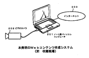
図2は、本発明を適用したWebコンテンツ作成システムの全体構成を示す。このWebコンテンツ作成システムは、収録現場(例えば、イベントが行われる会場や、事件の発生した現場等)において、ノート型パーソナルコンピュータ(以下単にコンピュータと呼ぶ)201を、IEEE1394インターフェースを介してビデオカメラ202に接続するとともに、ネットワークインターフェースを介してインターネット203に接続することによって構成されたものである。
【0038】
このWebコンテンツ作成システムで作成しようとするWebコンテンツは、収録現場の様子を、図3に例示するようにWebページ上で動画211及び記事(文字や静止画等)212で紹介するとともに、音声で紹介するものである。
【0039】
コンピュータ201は、Windows(登録商標)をOSとしており、AVデータをブロードバンド帯域用にエンコードするエンコードプログラム(例えばWindows(登録商標) Media)がインストールされているとともに、以下に説明するようなWebコンテンツ作成用プログラムが、このプログラムを記録したCD−ROMからインストールされている。ビデオカメラ202は、DV規格及びDVCAM規格に対応した機種である。
【0040】
図4は、コンピュータ201にインストールされているWebコンテンツ作成用プログラムによってコンピュータ201のディスプレイに表示されるGUI画面の構成要素を示す。このGUI画面は、メインUI1と、メインUI1を背景とするキャプチャUI2,再生・修正UI3,ブラウザUI4,タイムラインUI5,プレビューUI6と、メインUI1の上側のメニューバー7とを構成要素としている。
【0041】
メインUI1は、常時表示される。メインUI1には、次のような操作釦,アイコン及び表示部が存在する。
・作成したWebコンテンツをインターネット経由でコンテンツ配信用のサーバーにアップロードするための出力釦。
・GUI画面の画面モードとして、記録再生モード,編集モード,プレビューモードのうちの任意の1つを選択するための画面モード選択釦。
・一般的なOSの処理で行われているごみ箱機能を実現するためのごみ箱アイコン。
・コンピュータ201内のハードディスクについての情報を表示するディスク情報表示部。
【0042】
メニューバー7は、メインUI1の上側に固定して常時表示される。メニューバー7には、次のようなアイコンが存在している。
・AV編集やオーサリングの結果(作成したWebコンテンツ)を保存するための保存用アイコン。
・後出の図16のスケールエリア72の表示を、ミリ秒単位の表示と、33.33ミリ秒を1フレームとするフレーム単位の表示との間で切り替えるための切替用アイコン。
【0043】
図5は、各画面モードでのキャプチャUI2,再生・修正UI3,ブラウザUI4,タイムラインUI5,プレビューUI6の動作条件(表示/非表示の別や表示サイズ)を示す。また図6は、各画面モードでのGUI画面の表示状態を示す。
【0044】
メインUI1の画面モード選択釦で記録再生モードが選択されたときは、図5及び図6Aのように、プレビューUI6以外が表示され、ブラウザUI4は縮小表示される。
【0045】
この画面モード選択釦で編集モードが選択されたときは、図5及び図6Bのように、再生・修正UI3,ブラウザUI4及びタイムラインUI5が表示される(ブラウザUI4は拡大表示される)。
【0046】
この画面モード選択釦でプレビューモードが選択されたときは、図5及び図6Cのように、タイムラインUI5及びプレビューUI6が表示される。
【0047】
キャプチャUI2は、図2のビデオカメラ202で収録されるAVデータをコンピュータ201内のハードディスクに記録する操作や、記録中の映像の表示を行うためのGUIである。
【0048】
図7は、キャプチャUI2の画面を示す。キャプチャUI2には、次のような操作釦,表示部等が存在する。
【0049】
・ビデオカメラ202から送られるステータス情報やコンピュータ201内のハードディスクへのアクセス情報を表示するためのステータス表示部11。
・記録中の映像を表示するための映像表示部12。
・ビデオカメラ202をリモートコントロールするための複数の釦(巻き戻し/巻き戻し再生,停止,早送り/早送り再生,再生,コマ戻し,コマ送り,一時停止の各釦)から成るリモート操作部13。
【0050】
・AVデータの記録モードとして、ダイレクトモード,アフターモードのうちの任意の1つを選択するための記録モード選択釦14。
・ダイレクトモードにおいて、インポイントやアウトポイントが指定された時点のタイムコードの映像を静止画としてサムネイル表示するとともに、そのタイムコード及びインポイント/アウトポイントの区別を表示するための表示部であるマークバッファ部15。また、マークバッファ部15は、ダイレクトモードにおいてダブルクリックすることにより、現在表示中のポイントにキューアップして再生を開始するための操作部としての役割も有している。
【0051】
・AVデータのインポイント,アウトポイントをトグル操作で指定するためのマーク釦16。
・キューアップするポイントとして、インポイント,アウトポイント以外のポイントを指定するためのキューポイント釦17。
【0052】
・マーク釦16の操作によって直前に指定したインポイントやアウトポイントをキャンセルするためのキャンセル釦18。
・AVデータの記録の開始・終了操作を行うためのキャプチャ釦19。
・ビデオカメラ202から送られる音声のコンピュータ201での再生ボリュームを調整するためのボリューム釦20。
【0053】
モード選択釦14で選択されるダイレクトモード,アフターモードのうち、ダイレクトモードとは、ビデオカメラ202で撮影を行っている状態、あるいはリモート操作部13の操作でビデオカメラ202に収録済みビデオテープを再生させている状態で、キャプチャ釦19で記録開始操作を行うことにより、ビデオカメラ202から送られるAVデータをそのまま記録する(必要に応じて、表示部12の映像を見てマーク釦16でインポイント及びアウトポイントを指定しながら記録する)モードである。
【0054】
他方、アフターモードとは、最初に、リモート操作部13の操作でビデオカメラ202に収録済みビデオテープを再生させ、表示部12の映像を見てマーク釦16でインポイント及びアウトポイントを指定しておき、その後、キャプチャ釦19で記録開始操作を行うことにより、ビデオカメラ202にそのインポイントからアウトポイントまでの範囲のAVデータを自動的に再生させて、そのAVデータを記録するモードである。
【0055】
再生・修正UI3は、記録したAVデータを再生して記録時の編集点を修正したり新たな編集点を指定したりする操作や、再生中の映像の表示を行うためのGUIである。
【0056】
図8は、再生・修正UI3の画面を示す。再生・修正UI3には、次のような操作釦,表示部等が存在する。
【0057】
・コンピュータ201内のハードディスクへのアクセス情報を表示するためのステータス表示部21。
・再生中の映像を表示するための映像表示部22。
・AVクリップ(収録したAVデータのうち、インポイントからそれに続くアウトポイントまでの範囲)を再生させるための複数の釦等から成る再生操作部23。
【0058】
・再生対象のAVクリップを含むAVデータ全体を再生させるための全体再生チェックボックス24。
・インポイントを指定するためのインポイントマーク釦25。
・アウトポイントを指定するためのアウトポイントマーク釦26。
・釦25,26で指定されたインポイント,アウトポイントのタイムコード値をそれぞれ表示するためのタイムコード表示部27,28。
・釦25で指定されたインポイントと釦26で指定されたアウトポイントとの間のデュレーション(時間長)を表示するためのデュレーション表示部29。
【0059】
・キューアップするポイントとして、インポイント,アウトポイント以外のポイントを指定するためのキューポイント釦30。
釦30で指定されたキューポイントのタイムコード値を表示するためのタイムコード表示部31。
【0060】
・釦25及び26で指定したインポイントとアウトポイントとの間のAVデータを、新たなAVクリップとして決定するための新規釦32。
・再生対象として指定したAVクリップのインポイント,アウトポイントを、それぞれ釦25及び26で指定したインポイント,アウトポイントに変更するための上書き釦33。
・再生中の音声のコンピュータ201での再生ボリュームを調整するためのボリューム釦34。
【0061】
再生操作部23は、次のような複数の操作釦から成っている。
・再生を停止させるための停止釦。
・1倍速再生させるための再生釦。
・再生位置を1フレーム分進めるためのコマ送り釦。
・再生位置を1フレーム分戻すためのコマ送り釦。
・図9に示すような、再生範囲を示すスライダ35と、スライダ35上で再生位置を指すスライダノブ36。
【0062】
・インポイント,アウトポイント,キューポイントを、時間の進む方向に沿って1つずつキューアップするためのキューポイント送り釦。
・インポイント,アウトポイント,キューポイントを、時間の戻る方向に沿って1つずつキューアップするためのキューポイント戻し釦。
・再生範囲の先頭にキューアップするための先頭釦。
・再生範囲の最後尾にキューアップするための最後尾釦。
【0063】
図9のスライダ35が示す範囲は、再生対象のAVクリップ(チェックボックス24がチェックされた場合にはそのAVクリップを含むAVデータ全体)である。但し、AVデータの記録中であってAVデータ全体を再生する場合には、スライダ35が示す範囲は、そのAVデータのうち現在記録を終えている部分である(スライダ35の先頭,最後尾がそれぞれ記録開始点,現在記録中の点になる)。
【0064】
スライダノブ36は、任意の再生位置を頭出しするためにマウスでスライダ35上をスライドさせることが可能になっている。また、スライダノブ36は、キューアップ時にはキューポイントに移動し、再生時には再生位置の変化とともに移動する。
【0065】
ブラウザUI4は、AVクリップ,メディアファイル(メディアファイルについては後述する),マルチメディアデータ,エフェクト機能の素材,オーサリング時にWebコンテンツのレイアウトを決定するためのテンプレートの素材の表示及び選択操作や、マルチメディアデータ,エフェクト機能の素材,テンプレートの素材のインポートを行うためのGUIである。
【0066】
図10は、ブラウザUI4の画面を示す。ブラウザUI4には、表示領域41が存在するとともに、表示領域41の上側に次のような操作釦が存在する。
【0067】
・表示領域41に、AVクリップやメディアファイルやマルチメディアデータをタグの形式で一覧表示させるためのマルチメディア釦42。
・表示領域41に、エフェクト機能の素材をタグの形式で一覧表示させるためのエフェクト釦43。
・表示領域41に、オーディオの調整・編集用の画面を表示させるためのオーディオ釦44。
・表示領域41に、テンプレートの素材をタグの形式で一覧表示させるためのテンプレート釦45。
・表示領域41に、マルチメディアデータやエフェクト機能の素材やテンプレートの素材のインポート用の画面を表示させるためのインポート釦46。
【0068】
図11は、マルチメディア釦42の操作によって表示領域41に一覧表示されるAVクリップを示す。同図Aのように、それぞれ複数のAVクリップを格納したクリップフォルダ47が表示され、いずれか1つのクリップフォルダ47を開くと、同図Bのように、そのクリップフォルダ47内のAVクリップ48がタグの形式で一覧表示される。
【0069】
AVクリップやマルチメディアデータや素材の選択操作は、釦42,43,45によって表示領域41に一覧表示されたAVクリップやマルチメディアデータや素材のうちの所望のAVクリップやマルチメディアデータや素材をマウスでクリックすることによって行う。
【0070】
そして、選択したAVクリップやマルチメディアデータや素材を用いてAV編集やオーサリングを行う場合には、そのAVクリップやマルチメディアデータや素材を、マウスによるドラッグ&ドロップ等でタイムラインUI5における後出の図13のストーリーボードエリア61や図16のタイムラインエリア71に移動させる。
【0071】
また、選択したAVクリップやメディアファイルやマルチメディアデータや素材を削除する場合には、そのAVクリップやマルチメディアデータや素材をマウスによるドラッグ&ドロップ等で前述のメインUI1のごみ箱アイコンに移動させるた後、ごみ箱を空にする。
【0072】
他方、AVクリップを再生対象として指定する操作は、マルチメディア釦42によって表示領域41に一覧表示されたAVクリップ(図11BのAVクリップ48)をマウスでダブルクリックすることによって行う。
【0073】
インポート釦46によるインポート用の画面には、コンピュータ201内のハードディスクのCドライブや、図2のインターネット203経由でコンピータ201に接続されたサイトから、マルチメディアデータ(オーディオデータ,BGMデータ,静止画データ,アニメーションデータ,テキストデータ,HTML形式のデータ等)やエフェクト機能の素材やテンプレートの素材を検索してインポート対象として選択するための画面が表示される。
【0074】
タイムラインUI5は、複数のAVクリップを時間軸上で配列する操作(AV編集)や、AVデータと他のマルチメディアデータとのオーサリングや、作成したWebコンテンツの管理を行うためのGUIである。
【0075】
図12は、タイムラインUI5の画面を示す。タイムラインUI5には、表示領域51が存在するとともに、表示領域51の上側に次のような操作釦が存在する。
【0076】
・表示領域51に、AV編集のための画面を表示させるためのストーリーボード釦52。
・表示領域51に、オーサリングのための画面を表示させるためのタイムライン釦53。
・表示領域51に、携帯電話向けのWebコンテンツの作成のための画面を表示させるための携帯電話用釦54。
・表示領域51に、作成したWebコンテンツの管理用の画面を表示させるためのプロジェクト釦55。
【0077】
図13は、ストーリーボード釦52が操作された際の表示領域51の画面を示す。この画面には、ストーリーボードエリア61,BGMラインエリア62,釦エリア63,ステータスエリア64と、ストーリーボードエリア61及びBGMラインエリア62を左右にスクロールさせるためのスクロールバー65とが存在する。
【0078】
ストーリーボードエリア61には、それぞれ1つのAVクリップを配置することによって複数のAVクリップの映像を時間軸上で配列するためのビデオトレイ66と、トランジションエフェクト機能の素材を配置することによって2つのAVクリップの映像の切り替わり部分にエフェクトを付加するためのトランジショントレイ67とが、1つずつ交互に並んでいる。
【0079】
AVクリップが配置されたビデオトレイ66には、図14に示すように、そのAVクリップのインポイントのサムネイル画像68と、そのAVクリップのデュレーション(時間長)69とが表示されるとともに、エフェクトが付加されている場合にはそのことを示すアイコン70が表示される。各トランジショントレイ67には、付加されたトランジションエフェクトの種類を示す情報が表示される。
【0080】
BGMラインエリア62には、図15に示すように、ストーリーボードエリア61に配列した全てのAVクリップのデュレーションに対応する長さの部分が、残りの部分と区別して表示される。また、マルチメディアデータのうちのオーディオデータやBGMデータをBGMラインエリア62に配置することにより、AVクリップ中の音声データをそのオーディオデータやBGMデータに置き換えることができる。
【0081】
ビデオトレイ66やトランジショントレイ67やBGMラインエリア62へのAVクリップやエフェクト機能の素材やオーディオデータやBGMデータの配置操作は、前述のブラウザUI4の釦42や釦43による画面からAVクリップやエフェクト機能の素材やオーディオデータやBGMデータをドラッグ&ドロップ等で移動させることによって行う。
【0082】
釦エリア63には、次のような操作釦が存在する。
・AV編集の結果を、エンコードしない状態でプレビューするか、エンコードした状態でプレビューするかを選択するためのプレビュー切替え釦。
・プレビューの開始と一時停止とをトグル操作で行うためのプレビュー/ポーズ釦。
・開始したプレビューを終了するためのストップ釦。
【0083】
ステータスエリア64には、プレビュー実行時のステータス(現在の再生位置のタイムコード値)等が表示される。
【0084】
図16は、図12のタイムライン釦53が操作された際のタイムラインUI5の表示領域51の画面を示す。この画面には、タイムラインエリア71,スケールエリア72,釦エリア73,ステータスエリア74と、タイムラインエリア71を左右にスクロールさせるためのスクロールバー75とが存在する。
【0085】
タイムラインエリア71には、次のような各ラインが存在する。
・AVクリップを配置することによって複数のAVクリップの映像を時間軸上で配列したり、エフェクト機能の素材を配置することによって2つのAVクリップの映像の切り替わり部分にエフェクトを付加したりするためのビデオライン76。
【0086】
・AVクリップやマルチメディアデータのうちのオーディオデータを配置することにより、そのAVクリップの音声やオーディオデータを映像と同期させるためのオーディオライン77。
・AVクリップやマルチメディアデータのうちのBGMデータを配置することにより、そのAVクリップの音声やBGMデータを映像と同期させるためのBGMライン78。
・マルチメディアデータのうちの静止画データを配置することにより、その静止画データを映像と同期させるための静止画ライン79。
【0087】
・マルチメディアデータのうちのアニメーションデータを配置することにより、そのアニメーションデータを映像と同期させるためのアニメーションライン80。
・マルチメディアデータのうちのテキストデータを配置することにより、そのテキストデータを映像と同期させるためのためのテキストライン81。
・マルチメディアデータのうちのHTML形式のデータを配置することにより、そのHTML形式のデータを映像と同期させるためのためのためのHTMLライン82。
【0088】
スケールエリア72は、タイムラインエリア71の各ライン76〜82の目盛りを表示するものである。スケールエリア72の表示は、前述の図4のメニューバー7の切替用アイコンの操作により、図17に示すようなミリ秒単位の表示と、フレーム単位の表示との間で切り替え可能である。
【0089】
各ライン76〜82へのAVクリップやマルチメディアデータや素材の配置操作は、前述のブラウザUI4の釦42や釦43による画面からAVクリップやマルチメディアデータや素材をドラッグ&ドロップ等で移動させることによって行う。
【0090】
各ライン76〜82には、図18に示すように、配置したAVクリップやマルチメディアデータのデュレーションに対応する長さの部分に、そのAVクリップやマルチメディアデータのファイル名83が表示されるとともに、そのAVクリップやマルチメディアデータのインポイント,アウトポイントをスケールエリア72を見ながら変更する操作を行うためのドラッグアイコン84,85が表示される。
【0091】
さらに、ビデオライン76には、図19に示すように、配置したAVクリップのインポイントのサムネイル画像86や、付加したエフェクトを示すアイコン87も表示される。
【0092】
また、図13のストーリーボードエリア61にAVクリップやエフェクト機能の素材を配置した後で図16の画面を表示させた場合には、ビデオライン76には、サムネイル画像86やアイコン87として、ストーリーボードエリア61に配置したAVクリップのインポイントのサムネイル画像や、ストーリーボードエリア61でAVクリップに付加したエフェクトを示すアイコンがそのまま表示される。
【0093】
また、オーディオライン77には、図20に示すように、配置したオーディオデータを部分的に削除する操作を行うためのドラッグアイコン88,89も表示される。
【0094】
釦エリア73にも、図13の画面の釦エリア63と同じくプレビュー切替え釦,プレビュー/ポーズ釦及びストップ釦が存在する。
【0095】
ステータスエリア74には、プレビュー実行時のステータス(現在の再生位置のタイムコード値)等が表示される。
【0096】
図21は、図12の携帯電話用釦54が操作された際のタイムラインUI5の表示領域51の画面を示す。この画面には、ストーリーボードエリア91,テキストラインエリア92,釦エリア93,ステータスエリア94と、ストーリーボードエリア91を左右にスクロールさせるためのスクロールバー95とが存在する。
【0097】
ストーリーボードエリア91の機能,釦エリア93の操作釦,ステータスエリア94の表示は、図13の画面のストーリーボードエリア61,釦エリア63,ステータスエリア64におけるのとそれぞれ同様である。
【0098】
テキストラインエリア92の機能は、図16の画面のテキストライン81の機能と同じである。
【0099】
図13や図16や図21の画面上でのAV編集やオーサリングの結果を示す情報(作成したWebコンテンツに含まれるAVクリップ,マルチメディアデータ,エフェクト機能の素材や、そのWebコンテンツのレイアウトを決定するために選択したテンプレートの素材を示す情報)は、前述の図4のメニューバー7の保存用アイコンの操作により、次の図22のプロジェクトファイルエリア102に表示されたプロジェクトファイルに保存することができる。
【0100】
図22は、図12のプロジェクト釦55が操作された際のタイムラインUI5の表示領域51の画面を示す。この画面には、釦エリア101とプロジェクトファイルエリア102とが存在する。
【0101】
プロジェクトファイルエリア102は、プロジェクトファイルを表示するエリアである。
【0102】
釦エリア101には、次のような操作釦が存在する。
・新規のプロジェクトファイルを作成するための新規作成釦。
・プロジェクトファイルエリア102に表示されたプロジェクトファイルのうちマウスで選択したプロジェクトファイルを削除するための削除釦。
・プロジェクトファイルエリア102の表示モードとして、アイコンモード,詳細モードのうちの任意の1つを選択するための表示モード選択釦。
【0103】
図23Aは、釦エリア101の表示モード選択釦でアイコンモードが選択された際のプロジェクトファイルエリア102の画面を示す。各プロジェクトファイルがそれぞれアイコン103の状態で表示される。
【0104】
図23Bは、表示モード選択釦で詳細モードが選択された際のプロジェクトファイルエリア102の画面を示す。各プロジェクトファイルのプロジェクトファイル名,更新日時,サイズ及びコメントがリスト形式で表示される。
【0105】
図4のプレビューUI6は、図13や図16や図21の画面上でのAV編集やオーサリングの結果(作成したWebコンテンツ)のプレビュー表示を行うためのものである。表示内容がプレビューUI6の画面領域内に収まらない場合には、表示内容をスクロールさせるためのスクロールバーも表示される。
【0106】
図24は、Webコンテンツ作成用プログラムの全体構造の概要を示す。楕円の枠で囲んだ部分は、それぞれこのプログラムの構成要素(モジュールやプロセス)である。
【0107】
以下、図4〜図23に示したGUI画面上での操作や表示と関連させて、このプログラムによるコンピュータ201の処理を説明する。
【0108】
〔記録に関する処理〕
図4のメインUI1の画面モード選択釦で記録再生モードが選択され、図7のキャプチャUI2の記録モード選択釦14で選択した記録モード(ダイレクトモードまたはアフターモード)においてキャプチャ釦19でAVデータの記録の開始操作が行われると、図24の1:キャプチャマネージャにより、コンピュータ201からデータ線D1を介して外部機器(図2のビデオカメラ202)がAV/Cコマンドでコントロールされる。
【0109】
そして、このコマンドに応じてビデオカメラ202からデータ線D1を介してコンピュータ201に送られたAVデータ(DV規格またはDVCAM規格のストリームデータ)とステータス情報とが、1:キャプチャマネージャによって取り込まれる。
【0110】
1:キャプチャマネージャからは、このAVデータをAVIフォーマットのファイルとしてコンピュータ201内のハードディスクに保存させる保存要求が、データ線D3を介してディスク書き込み処理に送られる。ディスク書き込み処理では、この保存要求に基づいて、コンピュータ201内のハードディスクのDドライブにAVIファイルが記録される。このAVIファイルは、1:キャプチャマネージャによって管理される。
【0111】
また、このAVデータは、1:キャプチャマネージャによりデコードされて、図7のキャプチャUI2の映像表示部12に映像表示されるとともに、コンピュータ201の内蔵スピーカから音声出力される。
【0112】
他方、ビデオカメラ202からのステータス情報は、1:キャプチャマネージャによりデータ線D6を介してディスク情報表示に送られる。ディスク情報表示には、コンピュータ201内のハードディスクへのアクセス情報も、ディスク書き込み処理からデータ線D4を介して送られる。これらの情報は、ディスク情報表示により、図7のキャプチャUI2のステータス表示部11に表示される。
【0113】
また、ダイレクトモードでのAVデータの記録中に図7のキャプチャUI2のマーク釦16でインポイント,アウトポイントが指定されると、1:キャプチャマネージャにより、その指定時点の静止画のサムネイルとタイムコードとインポイント/アウトポイントの区別とが、図7のキャプチャUI2のマークバッファ部15に表示される。
【0114】
また、このインポイントからアウトポイントまでの範囲のAVデータの情報が、AVクリップ(キャプチャ済みのAVクリップ)の情報として、1:キャプチャマネージャから図24のデータ線D5を介して3:クリップ管理内の3−1:マルチメディア管理に送られる。
【0115】
他方、アフターモードにおいて記録の開始前にマーク釦16で指定されたインポイントからアウトポイントまでの範囲のAVデータの情報も、AVクリップ(未キャプチャAVクリップ)の情報として1:キャプチャマネージャから3−1:マルチメディア管理に送られる。
【0116】
そして、アフターモードでの記録の開始時には、3−1:マルチメディア管理からこの未キャプチャAVクリップの情報が1:キャプチャマネージャに送られ、その情報に基づいて1:キャプチャマネージャによるビデオカメラ202の再生範囲のコントロールが行われる。
【0117】
このようにして、ビデオカメラ202で収録されるAVデータのAVIファイルとしての記録や、AVIファイルの管理や、記録中の映像,ステータス情報,静止画の表示や、3−1:マルチメディア管理へのAVクリップの情報の送付が行われる。
【0118】
1:キャプチャマネージャによる処理のうち、AVIファイルの記録及び映像,静止画の表示に関する処理を具体的に説明すると、次の通りである。
【0119】
外部の機器から送られるAVデータを用いて短時間にWebコンテンツを作成するためには、このAVデータをコンピュータ201内のハードディスクに記録するのとほぼ同時にこのハードディスクから再生してAV編集やオーサリングを行えるようにすることが望まれる。
【0120】
ところが、AVIファイルの標準的なフォーマットは、最大2GB(ギガバイト)の可変長なデータを1つのファイルとして扱う形式になっている。
【0121】
そして、Windows(登録商標)におけるAVIファイルの再生方式では、ファイルとして完成している(記録を完了した)AVIファイルを再生することはできるが、ファイルとして完成していない(記録中の)AVIファイルを再生することはできない。
【0122】
DV規格やDVCAM規格のストリームデータでは、2GBは約9分30秒分のデータに相当する。したがって、ビデオカメラ202から送られるAVデータを標準的なAVIファイルとして記録したのでは、図25Aに示すように、最大で約9分30秒分待たなければそのAVデータを再生できないので、記録とほぼ同時に再生を行うことはできない。
【0123】
そこで、1:キャプチャマネージャによる処理では、最大2GBの可変長なデータではなく、2GBよりもはるかに短い8MB(メガバイト)(DV規格やDVCAM規格のストリームデータでは約2秒分)という固定長のデータを1つのAVIファイルとして扱うようにしている。これにより、図25Bに示すように、記録したAVデータを即時に(1つのAVIファイルが完成する約2秒後には)再生できるようになっている。
【0124】
図26は、1:キャプチャマネージャによるAVIファイルの構成を示す。AVIヘッダ部と、AVデータ部と、インデックス部とで構成されている。AVデータ部には、最初に映像データが格納され、次に音声データが格納される。インデックス部は、標準的なAVIファイルのインデックス部と異なり、映像データと音声データとに一度にアクセスできるように(再生時のデータ転送を効率するように)されている。
【0125】
ここで、Windows(登録商標)では、ハードディスクに対するアクセスは、複数のセクタから成るクラスタ単位で行われる。そして、このクラスタのサイズは、ハードディスクの容量とファイルシステムの形式とによって、図27A〜Cのいずれかに決定される。
【0126】
8MBというサイズは、図27のどのクラスタサイズに対しても整数倍または整数分の1になるので、無駄のないアクセスが可能になっている。
【0127】
1:キャプチャマネージャは、フィルタグラフ作成部と、キャプチャ部と、リモート制御部と、静止画作成部を含んでいる。
【0128】
フィルタグラフ作成部では、マイクロソフト社の‘Windows(登録商標) Direct Show’を使用することにより、図28に示すような各種フィルタ(一種のDLL)を組み合わせたフィルタグラフを構築する。
【0129】
このフィルタグラフ内のフィルタとしては、Windows(登録商標)標準のものを使用するだけでなく、‘Sample Grabber’,‘Video Rendarer’,‘FILE SAVE Filter’というようなWindows(登録商標)標準以外のものも使用している。
【0130】
‘Sample Grabber’は、BMP(ビットマップ)フォーマットの静止画を作成するためのフィルタである。
‘Video Rendarer’は、映像の表示に関するCPUの負荷を軽減するために、オリジナルで間引き表示を行うためのフィルタである。
【0131】
‘FILE SAVE Filter’は、ストリームデータを監視し、記録時にはストリームデータを8MB単位でバッファリングして順次ファイルとして保存させていくためのフィルタである。
【0132】
このフィルタグラフにより、外部のDV機器からの映像,音声をそれぞれ表示,スピーカから出力することや、外部のDV機器からのストリームデータを8MB単位のAVIファイルとして記録することや、このストリームデータから指定されたポイントの静止画を作成することができる。
【0133】
キャプチャ部は、外部のDV機器からのストリームデータの取り込み及び保存要求を行う。
【0134】
図29は、フィルタグラフ作成部及びキャプチャ部による1:キャプチャマネージャのフローを示す。ステップS1の「要求待ち」では、図7のキャプチャUI2のキャプチャ釦19の記録開始操作に基づくキャプチャ開始要求を待つ。そして、キャプチャ開始要求があると、ステップS2の「キャプチャ開始」で、後述のAVIファイルマネージャから、AVIファイル蓄積用バッファメモリのうちの2ブロック分を確保する。
【0135】
ステップS3の「AVIファイル名取得」及びステップS4の「新規メディアデータエントリ」では、AVIファイル名を取得してデータベースに登録する。
【0136】
ステップS5の「ストリームデータ蓄積・監視」では、送られてくるストリームデータをAVIファイル蓄積用バッファメモリに書き込むとともに、そのストリームデータからリアルステータス情報を取得する。取得するリアルステータス情報は、接続しているDV機器の接続状態,再生ステータス,DV機器内のテープの有無,記録日時,記録モード(SP/LP/DVCAM),フォーマット(NTSC/PAL),音声のチャンネル構成,音声の量子化ビット数,音声のサンプリング周波数,縦横比等である。そして、バッファメモリ1ブロック分のAVIファイルが蓄積されると、AVIファイルマネージャに対して、コンピュータ201内のハードディスクへのそのAVIファイルの保存要求を行う。
【0137】
キャプチャ釦19の記録終了操作に基づくキャプチャ終了要求があると、ステップS1の「要求待ち」に戻る。
【0138】
リモート制御部は、外部のDV機器をAV/Cコマンドでリモートコントロールする。リモート制御部が発行する具体的なコマンドは、PLAY,STOP,FREEZE,FF,REW,PLAY FASTEST FWD,PLAY FASTEST REW,STEP FWD,STEP REW,接続状態の情報やステータス情報やタイムコードの要求等である。リモート制御部は、図7のキャプチャUI2上での操作に基づき、また必要に応じてアイドル時に、外部のDV機器に対してコマンドを発行する。
【0139】
静止画作成部は、キャプチャ中にインポイント,アウトポイントが指定された際に静止画を作成する。図30は、静止画作成部の動作を示す。ダイレクトモードでのストリームデータの記録中に図7のキャプチャUI2のマーク釦16でインポイントやアウトポイントが指定されると、GUIから静止画の作成が要求される(ステップS11)。
【0140】
静止画作成部は、この要求があると、ストリームデータからインポイントやアウトポイントの指定時点のタイムコードのストリームデータを摘出し(ステップS12)、そのストリームデータから図28の‘Sample Grabber’でBMPデータを作成する(ステップS13)。
【0141】
その後、静止画作成部は、BMPデータを作成したことをGUIに通知する(ステップS14)。GUIは、この通知を受け取ると、その静止画のサムネイルとタイムコードとインポイント/アウトポイントの区別とを、図7のキャプチャUI2のマークバッファ部15に表示する。
【0142】
1:キャプチャマネージャによる処理のうち、AVIファイルの管理に関する処理を具体的に説明すると、次の通りである。
【0143】
前述のように、1:キャプチャマネージャによる処理では、ビデオカメラ202からのAVデータを8MB分ずつAVIファイルとして記録していく。AVIファイルの管理では、図31に示すように、一回のキャプチャ(図7のキャプチャUI2のキャプチャ釦19の記録開始操作から記録終了操作までの間の1回のAVデータの記録)によって作成された8MB分ずつの複数のAVIファイルを、メディアファイルという1つの連続したファイルとして扱う。このメディアファイルは、一回のキャプチャ毎に作成され、記録開始点と記録終了点とを管理する。
【0144】
AVIファイルが物理的なファイルであるのに対し、メディアファイルは論理ファイルであり、GUI画面上で1つのファイルとして見える(一回のキャプチャによる映像データが分割されていることをユーザーに意識させない)ようになっている。
【0145】
メディアファイルは前述の図10のブラウザUI4の表示領域41に、マルチメディア釦42の操作によって表示される。
【0146】
また、AVIファイルの管理では、一回のキャプチャによって作成された複数のAVIファイル同士のリンク情報を管理するためのAVIファイル管理テーブルを作成する。
【0147】
このAVIファイル管理テーブルでは、最初に、保存できる(管理可能な)AVIファイルの個数を決定する必要がある。コンピュータ201内のハードディスクのDドライブにAVIファイルを保存する場合、1つのAVIファイルは8MBなので、Dドライブの使用容量を決定することで管理可能なAVIファイルの最大数が決定される。ここでは、Dドライブの20GB分を使用し、したがって管理可能なAVIファイルの最大数を20GB/80MB=2560個とする。
【0148】
図32は、AVIファイル管理テーブルの構成を示す。AVIファイル管理テーブルは、AVI0ファイル管理部からAVI2559ファイル管理部までの2560個のAVIファイル管理部で構成される。各AVIファイル管理部は、AVI0ファイル管理部がファイル名00000000.AVIのAVIファイルを管理し、…AVI2559ファイル管理部がファイル名00002559.AVIのAVIファイルを管理するというように、それぞれ1つのAVIファイルを管理する。
【0149】
各AVIファイル管理部には、ブロックID,1つ前のブロックID,1つ先のブロックID,有効開始フレーム,有効終了フレーム,メディアファイルIDといったデータが書き込まれるとともに、使用/未使用フラグが存在する。
【0150】
ブロックIDは、そのAVIファイル管理部のインデックス値である。このインデックス値には、そのAVIファイル管理部で管理されるAVIファイルのファイル名(例えばAVI0ファイル管理部ではファイル名00000000.AVI)が充てられる。
【0151】
1つ前のブロックID,1つ先のブロックIDは、それぞれそのAVIファイル管理部の1つ前,1つ先のAVIファイル管理部のインデックス値である。
【0152】
メディアファイルIDは、そのAVIファイル管理部に書き込みを行ったメディアファイルを識別するためのIDである。
【0153】
使用/未使用フラグは、セットすることにより、そのAVIファイル管理部が使用中である(書き換えを禁止する)ことを表し、リセットすることにより、そのAVIファイル管理部が未使用である(書き換えを許可する)ことを表すフラグである。
【0154】
AVIファイル管理部には、初期化時にこれらのデータとして所定のデータが書き込まれ、キャプチャ時にデータの上書きが行われる。また、メディアファイルが削除された(図10のブラウザUI4の表示領域41に表示されたメディアファイルが図4のメインUI1のごみ箱アイコンに移動された後、ごみ箱が空にされた)場合にも、AVIファイル管理部内のデータを物理的に消去することはせず、使用/未使用フラグのリセットという論理的操作を行うことにより、ハードディスクに対するアクセスを極力抑えるようになっている。
【0155】
図33は、AVIファイル管理テーブルの使用状況例を示す。このうち図33Aは、初期化後、1回目のキャプチャでAVI0ファイル管理部からAVI3ファイル管理部までのデータが書き換えられ、2回目のキャプチャでAVI4ファイル管理部からAVI7ファイル管理部までのデータが書き換えられた状況を示している。
【0156】
また、図33Bは、その後3回目のキャプチャでAVI8ファイル管理部からAVI2559ファイル管理部までのデータが書き換えられた後、1回目のキャプチャ時に作成されたメディアファイルが削除された状況を示している。
【0157】
この状況では、AVI0ファイル管理部からAVI3ファイル管理部までの使用/未使用フラグがリセットされることにより、次回のキャプチャでAVI0ファイル管理部からAVI3ファイル管理部までのデータが書き換えられることになる。但し、この例では、AVI2ファイル管理部で管理されているAVIファイルの範囲にAVクリップが存在している(後述するように、そのAVクリップが図24の3−1:マルチメディア管理によって管理されている)ので、AVI2ファイル管理部の使用/未使用フラグはリセットされず、AVI2ファイル管理部のデータの書き換えは禁止される。
【0158】
図34は、メディアファイル内のデータを示す。メディアファイルは、メディアファイルID,メディアファイル名,先頭ブロックID,使用ブロック数,データサイズ,コメント,作成年月日,状態,キューリストといった各データを有する。
【0159】
メディアファイルIDは、そのメディアファイルを識別するためのIDである。メディアファイル名は、そのメディアファイルの名称である。先頭ブロックIDは、AVIファイル管理テーブル中のAVIファイル管理部のうち、キャプチャ時に最初に書き込みを行ったAVIファイル管理部のインデックス値(=AVIファイル名)である。
【0160】
使用ブロック数は、書き込みを行ったAVIファイル管理部の数であり、記録中は順次増加していく。コメントは、テキスト形式の簡単なメモである。作成年月日は、そのメディアファイルの作成年月日を、コンピュータ201自身の日付及び時刻またはビデオカメラ202からのストリームデータから読み取った日付及び時刻の情報を用いて表すものである。
【0161】
状態は、メディアファイルの作成状態(主に、現在記録中であるか、記録が完了しているか)を表す。キューリストは、図35に例示するように、図7のキャプチャUI2のキューポイント釦17で指定されたキューポイントをリスト管理するものである。
【0162】
図36は、AVIファイル管理テーブルとメディアファイルとの対応関係の一例を示す。この例では、AVI0ファイル管理部からAVI3ファイル管理部までがメディアファイル1に対応しており、AVI4ファイル管理部からAVI7ファイル管理部までがメディアファイル2に対応している。
【0163】
1:キャプチャマネージャの処理のうち、3−1:マルチメディア管理へのAVクリップの情報の送付に関する処理を具体的に示すと、図37及び図38の通りである。
【0164】
このうち図37はダイレクトモードでの処理であり、図7のキャプチャUI2のキャプチャ釦19で記録開始操作が行われると、記録中のAVデータから取得したその操作時点T1の静止画及びタイムコードを、インポイントの静止画及びタイムコードとアウトポイントの静止画及びタイムコードとの格納用のバッファメモリであるマークバッファ(キャプチャUI2のマークバッファ部15にはこのマークバッファ内の静止画及びタイムコードが表示される)に、インポイントの静止画及びタイムコードとして格納する。
【0165】
続いて、キャプチャUI2のマーク釦16が最初に操作されると、AVデータから取得したその操作時点T2の静止画及びタイムコードをアウトポイントの静止画及びタイムコードとしてマークバッファに格納するとともに、マークバッファ内のインポイントからアウトポイントまでの範囲のAVデータをAVクリップ(キャプチャ済みのAVクリップ)として仮決定する。
【0166】
続いて、マーク釦16が2番目に操作されると、仮決定したAVクリップを正式なAVクリップとして確定してそのAVクリップの情報を図24の3−1:マルチメディア管理に送るとともに、AVデータから取得したその操作時点T3の静止画及びタイムコードを新たなインポイントの静止画及びタイムコードとしてマークバッファに格納する。
【0167】
以下、マーク釦16が奇数番目に操作される毎に、その操作時点の静止画及びタイムコードを新たなアウトポイントの静止画及びタイムコードとしてマークバッファに格納するとともに、マークバッファ内のインポイントからこのアウトポイントまでの範囲のAVデータをAVクリップとして仮決定し、マーク釦16が偶数番目に操作される毎に、仮決定したAVクリップを正式なAVクリップとして確定してそのAVクリップの情報を3−1:マルチメディア管理に送るとともに、その操作時点の静止画及びタイムコードを新たなインポイントの静止画及びタイムコードとしてマークバッファに格納する。
【0168】
キャプチャUI2のキャンセル釦18が操作された場合には、直前のマーク釦16の操作によってマークバッファに格納されたインポイントまたはアウトポイントの静止画及びタイムコードをクリアし、その後のマーク釦16の操作時点の静止画及びタイムコードを新たなインポイントまたはアウトポイントの静止画及びタイムコードとしてマークバッファに格納する。
【0169】
キャプチャ釦19で記録終了操作が行われた際の処理は、マークバッファ内に最後にインポイントとアウトポイントとのどちらの静止画及びタイムコードが格納されたかによって異なる。
【0170】
図37のように時点T3でのマーク釦16の操作に続いて時点T4にキャプチャ釦19で記録終了操作が行われた場合のように、AVクリップを仮決定していない場合(マークバッファに直前にインポイントの静止画及びタイムコードを格納した場合)には、キャプチャ釦19で記録終了操作が行われた時点のタイムコードをアウトポイントとして、マークバッファに格納したインポイントからそのアウトポイントまでの範囲のAVデータをAVクリップとして確定して、そのAVクリップ情報を3−1:マルチメディア管理に送り、マークバッファをクリアする。
【0171】
他方、例えば図37の時点T3でマーク釦16の操作の代わりにキャプチャ釦19で記録終了操作が行われた場合のように、AVクリップを仮決定している場合(マークバッファに直前にアウトポイントの静止画及びタイムコードを格納した場合)には、その仮決定しているAVクリップを正式なAVクリップとして確定してそのAVクリップの情報を3−1:マルチメディア管理に送り、マークバッファをクリアする。
【0172】
図38はアフターモードでの処理であり、キャプチャUI2のマーク釦16が最初に操作されると、AVデータから取得したその操作時点T1の静止画及びタイムコードを、インポイントの静止画及びタイムコードとしてマークバッファに格納する。
【0173】
続いて、キャプチャUI2のマーク釦16が2番目に操作されると、AVデータから取得したその操作時点T2の静止画及びタイムコードをアウトポイントの静止画及びタイムコードとしてマークバッファに格納するとともに、マークバッファ内のインポイントからこのアウトポイントまでの範囲のAVデータをAVクリップ(未キャプチャAVクリップ)として仮決定する。
【0174】
続いて、マーク釦16が3番目に操作されると、仮決定したAVクリップを正式なAVクリップとして確定してそのAVクリップの情報を3−1:マルチメディア管理に送るとともに、AVデータから取得したその操作時点T3の静止画及びタイムコードを新たなインポイントの静止画及びタイムコードとしてマークバッファに格納する。
【0175】
以下、マーク釦16が偶数番目に操作される毎に、その操作時点の静止画及びタイムコードを新たなアウトポイントの静止画及びタイムコードとしてマークバッファに格納するとともに、マークバッファ内のインポイントからこのアウトポイントまでの範囲のAVデータをAVクリップとして仮決定し、マーク釦16が奇数番目に操作される毎に、仮決定したAVクリップを正式なAVクリップとして確定してそのAVクリップの情報を3−1:マルチメディア管理に送るとともに、その操作時点の静止画及びタイムコードを新たなインポイントの静止画及びタイムコードとしてマークバッファに格納する。
【0176】
〔再生に関する処理〕
ダイレクトモードでの記録中に、図7のキャプチャUI2のマーク釦16でインポイントやアウトポイントが指定されるとともにマークバッファ部15がダブルクリックされると、図24の1:キャプチャマネージャから、マークバッファ部15に静止画を表示中のポイントを示す情報が、データ線D32を介して2:再生・クリップ修正に送られる。そして、2:再生・クリップ修正から、そのポイントにキューアップしてAVデータを再生させる指示が、データ線D34を介してディスク読み出し処理に送られる。
【0177】
また、ダイレクトモードやアフターモードでの記録中や記録終了後に、図10のブラウザUI4の表示領域41にマルチメディア釦42の操作によって図11のようにAVクリップが表示され、そのうちのいずれかのAVクリップがダブルクリックされた(再生対象として指定された)状態で、図8の再生・修正UI3の再生操作部23で再生操作が行われると、2:再生・クリップ修正から、記録したAVデータのうちのそのAVクリップの先頭(全体再生チェックボックス24がチェックされた場合にはそのAVクリップを含むAVデータ全体の先頭)にキューアップしてAVデータを再生させる指示が、データ線D34を介してディスク読み出し処理に送られる。
【0178】
また、ダイレクトモードやアフターモードでの記録中や記録終了後に、図10のブラウザUI4の表示領域41にマルチメディア釦42の操作によって図11のようにAVクリップが表示されるとともに、図12のタイムラインUI5の表示領域51に、ストーリーボード釦52によって図13のストーリーボードエリア61が表示されるかまたはタイムライン釦53によって図16のビデオライン76が表示され、表示領域41から複数のAVクリップがドラッグ&ドロップによってストーリーボードエリア61またはビデオライン76に配列された(複数のAVクリップが時間軸上に配列されることによりAV編集が行われた)状態で、図8の再生・修正UI3の再生操作部23で再生操作が行われると、図24の4:タイムラインオーサリング内のAV編集から、AV編集の結果(AVクリップの配列状態)の情報が、データ線D22を介して2:再生・クリップ修正に送られる。そして、その情報に基づき、2:再生・クリップ修正から、記録したAVデータのうちそれらのAVクリップの部分を配列順に再生させる指示が、データ線D34を介してディスク読み出し処理に送られる。
【0179】
ディスク読み出し処理では、2:再生・クリップ修正からの指示に基づき、コンピュータ201内のハードディスクのDドライブに記録されているAVデータが再生され、AVデータを再生したことを示す情報が図24のデータ線D31を介して2:再生・クリップ修正に送られる。
【0180】
そして、2:再生・クリップ修正により、再生されたAVデータがデコードされて、図8の再生・修正UI3の映像表示部22に映像表示されるとともに、コンピュータ201の内蔵スピーカから音声出力される。
【0181】
このようにして、ビデオカメラ202からのAVデータの記録中や記録終了後に、2:再生・クリップ修正によってそのAVデータの再生及び表示が行われる。
【0182】
2:再生・クリップ修正のうち、AVデータの再生に関する部分(再生マネージャと呼ぶことにする)の処理を具体的に説明すると、次の通りである。
【0183】
図39は、再生マネージャの構造及び動作フローを示す。再生マネージャは、メイン処理121,映像再生部122及び音声再生部123を含んでおり、映像データ蓄積用のバッファメモリ124及び音声データ蓄積用のバッファメモリ125を使用する。
【0184】
バッファメモリ124は、8MB(AVIファイル1個分)×4ブロックの容量を有している。バッファメモリ125は、量子化ビット数16ビット、サンプリング周波数48kHzの音声データ1秒分(2バイト×48000)×4ブロックの容量を有している。
【0185】
GUIからの要求(図7のキャプチャUI2のマークバッファ部15のダブルクリックや図8の再生・修正UI3の再生操作部23の操作による要求)が、図示しないコマンドキューに入れられ、そのコマンドキューから1つずつ取り出されてメイン処理121に送られる。
【0186】
メイン処理121は、この要求に基づき、映像再生部122,音声再生部123にそれぞれ映像,音声の再生要求を送るとともに、後述する(図42の)AVIファイルマネージャ131にAVIファイルのロード要求を送る。
【0187】
AVIファイルマネージャ131は、後述するように、このロード要求に基づき、AVIファイルのうちの映像データ,音声データをそれぞれバッファメモリ124,バッファメモリ125に書き込む。
【0188】
映像再生部122,音声再生部123は、それぞれメイン処理121からの再生要求に基づいて、バッファメモリ124,バッファメモリ125から映像データ,音声データを読み出す。
【0189】
映像再生部122は、AVIファイル中の1フレーム分の映像データ(DVフォーマット)をBMPデータに変換するビデオデコーダを含んでいる。メイン処理121は、映像の再生要求として、コンピュータ201の内部タイマを使用して1フレーム分の時間(1/30秒)毎にイベントを発生し、各イベント毎のタイミングで映像再生部122に変換の実行を要求する。ビデオデコーダは、バッファメモリ124から読み出した映像データを、このイベント毎のタイミングでBMPデータに変換する。
【0190】
図40は、バッファメモリ124に対する映像データの書き込み・読み出し手順を示す。初期状態では、図40Aに示すように、ロード位置を示すライトポインタWP,読み出し位置を示すリードポインタRPがそれぞれバッファメモリ124の先頭を指しており、バッファメモリ124に書き込まれているデータはない。
【0191】
メイン処理121から再生要求があると、AVIファイル2個分の映像データをAVIファイルマネージャ131に要求し、図40Bに示すように、その映像データがバッファメモリ124に書き込まれてライトポインタWPが更新される。
【0192】
その後、バッファメモリ124からの映像データの読み出しを開始し、リードポインタRPを更新する。そして、図40Cに示すようにAVIファイル1個分の映像データをバッファメモリ124から読み出す(リードポインタRPがバッファメモリ124の1つ目のブロックの終端に達する)と、AVIファイルマネージャ131に次のAVIファイル1個分の映像データを要求し、その映像データがバッファメモリ124に書き込まれてライトポインタWPが更新される。
【0193】
以下、AVIファイル1個分の映像データをバッファメモリ124から読み出す毎(リードポインタRPがブロックの終端に達する毎)に、AVIファイルマネージャ131に次のAVIファイル1個分の映像データを要求し、その映像データがバッファメモリ124に書き込まれてライトポインタWPが更新されていく。
【0194】
音声再生部123は、Microsoft Direct Soundを使用する。Microsoft Direct Soundは、複数の音声データの再生やボリューム,パン,スピードの制御が可能であり、音声データの再生位置をサンプリング点の精度で求めることにより、コンピュータ201の内部タイマを使用せずに各フレームの音声データを再生する。
【0195】
バッファメモリ125に対する音声データの書き込み・読み出し手順は、映像データについて図40に示したのと全く同じである。
【0196】
例えばマイクロソフト社のAVIファイル再生用のミドルウェアであるWindows(登録商標) Direct Showを使用してAVIファイル中の映像データ及び音声データの両方をバッファメモリを介して再生した場合には、バッファメモリの終端から先頭にシークした際に、再生される音声に音飛びが発生することが確認されている。
【0197】
これに対し、このように映像データ,音声データを互いに別の処理によって再生する(音声データはMicrosoft Direct Soundを使用して再生する)ことにより、再生される音声に音飛びが発生することが防止される。
【0198】
なお、再生中にGUIから別のポイントへのキューアップ要求があった場合(図8の再生・修正UI3の再生操作部23のコマ送り釦やキューポイント送り釦等が操作された場合)には、メイン処理121は、映像再生部122,音声再生部123にそれぞれ再生の停止を要求するとともに、AVIファイルマネージャ131に対し、それまでのロード要求の破棄と、新たなキューアップ先のAVIファイルのロードとを要求する。
【0199】
そして、AVIファイルマネージャ131からロードの完了が伝えられると、メイン処理121は、映像再生部122,音声再生部123にそれぞれ新たに再生要求を送る。
【0200】
ところで、映像再生部122では前述のようにコンピュータ201の内部タイマを使用して1フレーム分の時間毎にイベントを発生するが、一般に、パーソナルコンピュータの内部タイマを使用したイベントの発生タイミングを完全に正確に1フレーム分の時間と一致させることは困難である。したがって、映像再生部122での各フレームの映像データのBMPデータへの変換タイミングは、そのままでは、音声再生部123による同じフレームの音声データの再生タイミングからしだいにずれていってしまう。
【0201】
そこで、再生マネージャでは、映像再生部122,音声再生部123での映像,音声データの再生の進行状態を一定の時間毎(例えば1秒毎)に監視し、映像データの再生のほうが進んでいる場合には映像再生部122を制御して同じフレームの映像データを再度再生させ、逆に映像データの再生のほうが遅れている場合には映像再生部122を制御して映像データの再生位置を1フレーム分先に送ることにより、音声データを基準として映像データの再生をそれに同期させる。
【0202】
図41は、この同期制御の例を示しており、音声データの(n+1)フレーム目の再生タイミングで監視を行っている。
【0203】
図41Aでは、音声データの(n+1)フレーム目の再生タイミングで映像データは既に(n+2)フレーム目が再生されている(映像データの再生のほうが進んでいる)ので、(n+2)フレーム目の映像データを再度再生させている。
【0204】
図41Bでは、音声データの(n+1)フレーム目の再生タイミングで映像データはまだnフレーム目が再生されている(映像データの再生のほうが遅れている)ので、映像データの再生位置を1フレーム分先の(n+2)フレーム目に送っている。
【0205】
この同期制御により、前述のように映像の再生と音声の再生とをそれぞれに適した処理(音声については音飛びが防止されるような処理)によって行いつつ、映像と音声とを同期して再生することができる。
【0206】
〔記録と再生との調整に関する処理〕
ここまでに説明したように、図24の1:キャプチャマネージャによってAVIファイルが記録され、2:再生・クリップ修正のうちの再生マネージャによってAVIファイルが再生されるが、コンピュータ201内のハードディスクに対してAVIファイルの記録のためのアクセスと再生のためのアクセスとをそれぞれ勝手に行った場合には、CPUの負荷が増大することにより記録や再生に要する時間が長くなってしまうので、たいへん非効率的である。
【0207】
そこで、図24のディスク書き込み処理とディスク読み出し処理との両方によって実現される機能として、コンピュータ201内のハードディスクへの記録のためのアクセスと再生のためのアクセスとを調整するAVIファイルマネージャが設けられている。
【0208】
図42は、このAVIファイルマネージャの構造を示す。AVIファイルマネージャ131は、キャプチャマネージャ141(図24の1:キャプチャマネージャ)からのAVIファイルの保存要求及び再生マネージャ142からのAVIファイルのロード要求を受け付ける要求受付部132と、要求受付部132で受け付けられた保存要求,ロード要求をそれぞれ積み上げていく保存要求キュー133,ロード要求キュー134と、保存要求キュー133,ロード要求キュー134から1つずつ取り出された保存要求,ロード要求に基づいてコンピュータ201内のハードディスク143にAVIファイルの記録,再生のためにアクセスするファイルアクセス部135とを含んでおり、8MB×4ブロックのバッファメモリ136を使用する。
【0209】
バッファメモリ136は、1:キャプチャマネージャから保存要求のあったAVIファイルを一時記憶するためのものである。図43Aに示すように、初期状態では、1:キャプチャマネージャが、バッファメモリ136のうちの2ブロック分を資源として確保する。
【0210】
そして、記録時には、1:キャプチャマネージャは、確保してあるバッファメモリ136にAVIファイルを書き込み、1ブロック分のAVIファイルが蓄積されると、図43Bに示すように、そのAVIファイルの保存要求をAVIファイルマネージャ131に送るとともに、新たな1ブロック分のバッファメモリ136を確保する。
【0211】
AVIファイルマネージャ131では、この保存要求が保存要求キュー133から取り出されると、AVIファイルが蓄積された1ブロック分のAVIファイルがバッファメモリ136から読み出され、そのAVIファイルがファイルアクセス部135によってコンピュータ201内のハードディスク143に保存される。そして、そのAVIファイルを蓄積していたブロックが、クリアされてAVIファイルマネージャ131の資源とされる。
【0212】
図44は、キャプチャマネージャ141からの保存要求のデータ構造を示す。AVIファイルを蓄積しているバッファメモリ136のアドレスと、AVIファイルIDと、AVIファイルが属するメディアファイルを示す情報とを含んでいる。
【0213】
再生マネージャ142は、バッファメモリ136を使用せず、前述のように再生マネージャ側のバッファメモリ(図39のバッファメモリ124及び125)を使用する。これは、再生マネージャがロードを要求するAVIファイルのデータ量が8MB未満である場合もあるため、常に1ブロック分のバッファメモリ136を占有するのは非効率的だからである。
【0214】
図45は、再生マネージャ142からのロード要求のデータ構造を示す。AVIファイルIDと、読込み開始フレームと、読込み元フレーム数と、音声データのみ/映像データのみ/音声データ及び映像データの区別と、読込み先アドレスと、読込み先オフセットの情報とを含んでいる。
【0215】
このAVIファイルマネージャでコンピュータ201内のハードディスクに対するAVIファイルの記録のためのアクセスと再生のためのアクセスとが調整されることにより、この記録のためのアクセスと再生のためのアクセスとをそれぞれ勝手に行う場合と比較して、CPUの負荷が軽減されるので、記録や再生に要する時間が短くなる。
【0216】
〔AVクリップの修正等に関する処理〕
AVデータの再生中には、記録時に図7のキャプチャUI2のマーク釦16で指定したインポイントやアウトポイントを修正したい場合がある。そうした場合に、図8の再生・修正UI3のインポイントマーク釦25やアウトポイントマーク釦26で改めてインポイントやアウトポイントを指定するとともに上書き釦33を操作すると、そのインポイントやアウトポイントの情報が、再生対象として指定したAVクリップの修正後のインポイントやアウトポイントの情報として、2:再生・クリップ修正から図24のデータ線D6を介して3:クリップ管理内の3−1:マルチメディア管理に送られる。
【0217】
さらに、そのAVクリップを含むWebコンテンツが既に作成されて保存されている(プロジェクトファイルに保存されている)場合は、この修正後のインポイントやアウトポイントの情報は、2:再生・クリップ修正から図24のデータ線D14を介して4:タイムラインオーサリング内のプロジェクト管理にも送られる。
【0218】
また、AVデータの再生中に、図8の再生・修正UI3のインポイントマーク釦25やアウトポイントマーク釦26でインポイントやアウトポイントを指定するとともに新規釦32を操作すると、そのインポイント及びアウトポイントの情報が、新たなAVクリップとして、2:再生・クリップ修正から3−1:マルチメディア管理に送られる。
【0219】
〔マルチメディアデータ等のインポートに関する処理〕
図10のブラウザUI4の表示領域41にインポート釦46によってインポート用の画面が表示され、この画面上で、インターネット203経由でコンピュータ201に接続されたサイトから検索したマルチメディアデータやエフェクト機能の素材やテンプレートの素材のファイルをインポートする操作が行われると、図24のインポートにより、外部機器(このサイトのサーバー)からデータ線2を介してそのファイルがダウンロードされる。
【0220】
また、この画面上で、コンピュータ201内のハードディスクのCドライブから検索したマルチメディアデータやエフェクト機能の素材やテンプレートの素材のファイルをインポートする操作が行われると、図24のインポートにより、コンピュータ201内のハードディスクのCドライブからデータ線33を介してそのファイルが取り込まれる。
【0221】
図24のインポートに取り込まれたマルチメディアデータ,エフェクト機能の素材,テンプレートの素材のファイルは、図24のファイル変換によって所定の形式のファイルにフォーマット変換され(例えば静止画データはJPEG形式に変換され)、図24のディスク書き込み処理によってコンピュータ201内のハードディスク(マルチメディアデータはDドライブ、エフェクト機能の素材,テンプレートの素材はCドライブ)に記録される。
【0222】
また、図24のインポートからは、取り込んだマルチメディアデータ,エフェクト機能の素材,テンプレートの素材を知らせる情報が、それぞれデータ線D12,D16,D17を介して3:クリップ管理内の3−1:マルチメディア管理,3−2:エフェクト管理,3−3:テンプレート管理に送られる。
【0223】
〔AVクリップやマルチメディアデータ等の管理〕
前述のように、キャプチャ中や再生中にインポイント及びアウトポイントを指定する操作が行われると、1:キャプチャマネージャや2:再生・クリップ修正から、AVクリップの情報が図24のデータ線D5やD6を介して3:クリップ管理内の3−1:マルチメディア管理に送られる。
【0224】
また、前述のように、図24のインポートに取り込まれたマルチメディアデータ,エフェクト機能の素材,テンプレートの素材の情報が、それぞれデータ線D12,D16,D17を介して3:クリップ管理内の3−1:マルチメディア管理,3−2:エフェクト管理,3−3:テンプレート管理に送られる。
【0225】
また、コンピュータ201のキーボードでマルチメディアデータの一つとしてテキストデータが入力されると、そのテキストデータの情報が、図24のテキスト編集からデータ線D13を介して3−1:マルチメディア管理に送られる。
【0226】
3−1:マルチメディア管理,3−2:エフェクト管理,3−3:テンプレート管理では、それぞれこのAVクリップ及びマルチメディアデータ,エフェクト機能の素材,テンプレートの素材が管理される。
【0227】
3−1:マルチメディア管理では、個々のAVクリップは、図46に示すようなクリップデータとして管理される。このクリップデータは、クリップID(AVクリップの認識コード)と、インポイントビットマップID(インポイントのサムネイル画像の認識コード)と、インポイントタイムコード(インポイントのフレーム番号)と、インポイントブロックID(インポイントが存在するAVIファイル管理テーブルのインデックス値)と、アウトポイントビットマップID(アウトポイントのサムネイル画像の認識コード)と、アウトポイントタイムコード(アウトポイントのフレーム番号)と、アウトポイントブロックID(アウトポイントが存在するAVIファイル管理テーブルのインデックス値)と、コメントと、所属メディアファイルID(AVクリップが属するメディアファイルのID)と、キューポイントデータ(AVクリップ内のキューポイントを管理するデータ)と、オーディオミュート情報とで構成されている。
【0228】
図47A,Bは、クリップデータの構成要素であるキューポイントデータの構成,AVクリップとキューポイントとの関係をそれぞれ示す。キューポイントデータは、クリップID(キューポイントが所属するAVクリップのクリップID)と、AVIファイルID(キューポイントが所属するAVIファイルの番号)と、フレーム(キューポイントのフレーム番号)と、ビットマップID(キューポイントのサムネイル画像の認識コード)とで構成されている。
【0229】
図48は、クリップデータの構成要素であるオーディオミュート情報の構成を示す。オーディオミュート情報は、Lボリューム(ステレオ音声の左側の音量),Rボリューム(ステレオ音声の右側の音量),ミュートビットマップ(各フレームに対してオーディオのオンオフを決めるビットマップデータ)で構成されている。
【0230】
3−1:マルチメディア管理では、図49に示すように、複数のクリップデータを、クリップデータリストに載せるとともに、クリップフォルダに格納する。そして、複数のクリップフォルダをクリップフォルダテーブルで管理する。図50は、クリップフォルダテーブルにおいて個々のクリップフォルダに付与されるデータを示す。このクリップフォルダデータは、クリップフォルダID(クリップフォルダの認識コード)と、クリップフォルダタイプ(映像データ及び音声データを含むAVクリップか、音声データのみを含むGMクリップか、その他のクリップかの区別)とで構成されている。
【0231】
2:再生・クリップ修正から前述のAVクリップの修正後のインポイントやアウトポイントの情報が送られると、3−1:マルチメディア管理では、そのAVクリップについてのクリップデータ中のインポイントタイムコードやアウトポイントタイムコード等が修正される。
【0232】
3−1:マルチメディア管理に管理されているAVクリップのうち未キャプチャAVクリップの情報は、アフターモードでの記録の開始時に、3−1:マルチメディア管理から図24のデータ線D5を介して1:キャプチャマネージャに送られる。
【0233】
3−1:マルチメディア管理に管理されているAVクリップ及びマルチメディアデータは、図10のブラウザUI4の表示領域41に、マルチメディア釦42の操作によって表示される。
【0234】
3−2:エフェクト管理に管理されているエフェクト機能の素材は、この表示領域41に、エフェクト釦43の操作によって表示される。
【0235】
3−3:テンプレート管理に管理されているテンプレートの素材は、この表示領域41に、テンプレート釦45の操作によって表示される。
【0236】
図10のブラウザUI4のマルチメディア釦42やエフェクト釦43による画面に表示されたAVクリップやBGMデータやエフェクト機能の素材が、図12のタイムラインUI5のストーリーボード釦52による図13の画面のストーリーボードエリア61やBGMラインエリア63に配置されると、そのAVクリップやBGMデータを示す情報(AVクリップについては、複製したクリップデータ)が3−1:マルチメディア管理から図24のデータ線D7を介して4:タイムラインオーサリングのAV編集に送られるとともに、そのエフェクト機能の素材を示す情報が2:エフェクト管理から図24のデータ線D20を介して4:タイムラインオーサリングのAV編集に送られる。
【0237】
また、ブラウザUI4のテンプレート釦45による画面でWebコンテンツのレイアウトを決定するためのテンプレートの素材が選択され、ブラウザUI4のマルチメディア釦42やマルチメディア釦43による画面に表示されたAVクリップやマルチメディアデータやエフェクト機能の素材が図12のタイムラインUI5のタイムライン釦53による図16の画面のタイムラインエリア71に配置されると、そのAVクリップやマルチメディアデータを示す情報(AVクリップについては、複製したクリップデータ)が3−1:マルチメディア管理から図24のデータ線D19を介して4:タイムラインオーサリングのオーサリングに送られ、そのエフェクト機能の素材を示す情報が3−2:エフェクト管理から図24のデータ線D18を介して4:タイムラインオーサリングのオーサリングに送られ、そのテンプレートの素材を示す情報が3−3:テンプレート管理から図24のデータ線D21を介して4:タイムラインオーサリングのオーサリングに送られる。
【0238】
〔AV編集及びオーサリングに関する処理〕
図13のストーリーボードエリア61や図16のビデオライン76に複数のAVクリップが配列された(AV編集が行われた)状態で、図8の再生・修正UI3の再生操作部23で再生操作が行われると、前述のように、そのAV編集の結果(AVクリップの配列状態)の情報が、図24の4:タイムラインオーサリング内のAV編集からデータ線D22を介して2:再生・クリップ修正に送られる。
【0239】
図13の画面のストーリーボードエリア61やBGMラインエリア63にAVクリップやBGMデータやエフェクト機能の素材を配置することによってAV編集を行い、そのAV編集の結果をWebコンテンツとして保存するために図4のメニューバー7の保存用アイコンがクリックされると、そのWebコンテンツに含まれるAVクリップ,BGMデータ,エフェクト機能の素材を示す情報(AVクリップについてはクリップデータ)とそれらの時間軸上での配列状態を示す情報とが、図24の4:タイムラインオーサリングにおいてAV編集からデータ線D4−4を介してプロジェクト管理に送られる。
【0240】
また、図16の画面のタイムラインエリア71にAVクリップやマルチメディアデータやエフェクト機能の素材を配置することによってAV編集やオーサリングを行い、そのAV編集やオーサリングの結果をWebコンテンツとして保存するために図4のメニューバー7の保存用アイコンがクリックされると、そのWebコンテンツに含まれるAVクリップ,マルチメディアデータ,エフェクト機能の素材を示す情報(AVクリップについてはクリップデータ)と、それらの時間軸上での配列状態を示す情報と、選択されているテンプレートの素材を示す情報とが、図24の4:タイムラインオーサリングにおいてオーサリングからデータ線D4−6を介してプロジェクト管理に送られる。
【0241】
〔プレビューに関する処理〕
図13の画面や図16の画面で作成したWebコンテンツをプレビューするために釦エリア63や釦エリア73のプレビュー/ポーズ釦でプレビュー開始操作が行われると、4:タイムラインオーサリングのAV編集やオーサリングから、そのWebコンテンツに含まれるAVクリップ,マルチメディアデータ,エフェクト機能の素材や、それらの時間軸上での配列状態を示す情報や、そのWebコンテンツのレイアウトを決定するテンプレートの素材を示す情報が、図24のデータ線D22等を介して2:再生・クリップ修正に送られる(図24ではオーサリングから2:再生・クリップ修正へのデータ線の図示は省略されている)。
【0242】
そして、その情報に基づき、2:再生・クリップ修正から、それらのAVクリップ,マルチメディアデータ,エフェクト機能の素材,テンプレートの素材を再生させる指示が、データ線D34を介してディスク読み出し処理に送られる。
【0243】
ディスク読み出し処理では、この指示に基づき、コンピュータ201内のハードディスクのDドライブに記録されているAVデータ,マルチメディアデータやCドライブに記録されているエフェクト機能の素材,テンプレートの素材が再生され、それらを再生したことを示す情報が図24のデータ線D24を介して4:タイムラインオーサリングのオーサリングプレビューに送られる。
【0244】
そして、4:タイムラインオーサリングのオーサリングプレビューにより、再生されたAVデータがデコードされ、そのWebコンテンツが図4のプレビューUI6に映像表示されるとともにコンピュータ201の内蔵スピーカから音声出力される。
【0245】
また、釦エリア63や釦エリア73のプレビュー/ポーズ釦でプレビュー開始操作が行われた際に、プレビュー切替え釦で、エンコードした状態でプレビューすることが選択されていた場合には、再生されたAVデータが、コンピュータ201にインストールされているエンコードプログラムによってブロードバンド帯域用にエンコードされる。
【0246】
図24のエンコード管理からは、このエンコード済みのAVデータをコンピュータ201内のハードディスクのCドライブに一時的に記憶させる要求が、ディスク書き込み処理に送られる。ディスク書き込み処理では、この要求に基づいて、コンピュータ201内のハードディスクのCドライブにエンコード済みのAVデータが一時記憶される。
【0247】
そして、この一時記憶されたエンコード済みのAVデータが図24のディスク読み出し処理によってCドライブから再生され、それらを再生したことを示す情報がディスク読み出し処理からデータ線D24を介して4:タイムラインオーサリングのオーサリングプレビューに送られて、エンコードされた状態のWebコンテンツがオーサリングプレビューによりプレビューUI6に映像表示されるとともにコンピュータ201の内蔵スピーカから音声出力される。
【0248】
〔プロジェクト管理〕
前述のように、図13の画面や図16の画面でのAV編集やオーサリングの結果をWebコンテンツとして保存するために図4のメニューバー7の保存用アイコンがクリックされると、そのWebコンテンツに含まれるAVクリップ,マルチメディアデータ,エフェクト機能の素材や、それらの時間軸上での配列状態を示す情報や、テンプレートの素材を示す情報が、図24の4:タイムラインオーサリングにおいてAV編集やオーサリングからプロジェクト管理に送られる。
【0249】
プロジェクト管理では、作成されたWebコンテンツをプロジェクトファイルとして管理する。プロジェクトファイルには、図51に示すように、Webコンテンツでの配列順に並べられたAVクリップのクリップデータのリストや、Webコンテンツでの再生順に並べられたBGMデータ(BGMクリップ)等のマルチメディアデータのクリップについてのデータのリストが含まれる。また、オーサリングが行われた場合には、プロジェクトファイルには、テンプレートの素材の情報も含まれる。
【0250】
プロジェクト管理では、図51に示すように、複数のプロジェクトファイルをプロジェクトテーブルで管理する。
【0251】
2:再生・クリップ修正から前述のAVクリップの修正後のインポイントやアウトポイントの情報が送られると、プロジェクト管理では、プロジェクトファイル内のそのAVクリップについてのクリップデータ中のインポイントタイムコードやアウトポイントタイムコード等が修正される。
【0252】
プロジェクト管理に管理されているプロジェクトファイルは、図12のタイムラインUI5のプロジェクト釦55の操作により、図22のプロジェクトファイルエリア102に表示される。
【0253】
図52は、以上にAVIファイルとメディアファイルとAVクリップとプロジェクトファイルとの関係を示す。図2のビデオカメラ202からコンピュータ201に送られるAVデータが、8MBずつのAVIファイルとしてコンピュータ201内のハードディスクに記録される。そして一度のキャプチャによって記録された複数のAVIファイルがメディアファイルとして管理されるとともに、AVデータのうちインポイントからそれに続くアウトポイントまでの範囲がAVクリップとしてクリップフォルダで管理される。また、AV編集によって配列された複数のAVクリップが、BGMクリップ等のマルチメディアデータのクリップとともにプロジェクトファイルとして管理される。
【0254】
〔AVクリップやプロジェクトファイル等の削除に関する処理〕
図10のブラウザUI4の表示領域41にマルチメディア釦42の操作によって表示されたAVクリップがマウスによるドラッグ&ドロップ等でメインUI1のごみ箱アイコンに移動された後、ごみ箱が空にされると、図24の6:ごみ箱から、そのAVクリップを示す情報がデータ線D15を介して3−1:マルチメディア管理に送られる。
【0255】
そして、この情報に基づき、3−1:マルチメディア管理でそのAVクリップのクリップのクリップデータが削除される。
【0256】
ブラウザUI4の表示領域41にマルチメディア釦42の操作によって表示されたメディアファイルがマウスによるドラッグ&ドロップ等でメインU1のごみ箱アイコンに移動された後、ごみ箱が空にされると、そのメディアファイルを示す情報が、6:ごみ箱から図24のデータ線D15を介して3−1:マルチメディア管理に送られる。そして、3−1:マルチメディア管理から、そのメディアファイルを示す情報と、そのメディアファイルで管理されているAVIファイルの範囲に存在しているAVクリップを示す情報とが、データ線D15を介して1:キャプチャマネージャに送られる。
【0257】
1:キャプチャマネージャでは、それらの情報に基づき、図33に例示したように、AVIファイル管理テーブルのうちそのメディアファイルが対応しているAVIファイル管理部(AVクリップが存在しているAVIファイル管理部を除く)の使用/未使用フラグがリセットされる。
【0258】
図12のタイムラインUI5のプロジェクト釦55の操作によって図22のプロジェクトファイルエリア102に表示されたプロジェクトファイルがマウスによるドラッグ&ドロップ等でメインUI1のごみ箱アイコンに移動された後、ごみ箱が空にされると、そのプロジェクトファイルを示す情報が、6:ごみ箱から図24のデータ線D26を介して4:タイムラインオーサリングのプロジェクト管理に送られる。
【0259】
4:タイムラインオーサリングのプロジェクト管理では、この情報に基づき、そのプロジェクトファイルが削除される。
【0260】
〔Webコンテンツのアップロード等に関する処理〕
図12のタイムラインUI5のプロジェクト釦55の操作によって図22のプロジェクトファイルエリア102に表示されたプロジェクトファイルのうちのいずれかのプロジェクトファイルがマウスで選択され、図4のメインUI1の出力釦が操作されると、そのプロジェクトファイルを示す情報が、図24の4:タイムラインオーサリングのプロジェクト管理からデータ線D28を介して5:出力に送られる。
【0261】
そして、その情報に基づき、5:出力から、そのプロジェクトファイルで管理されているAVクリップ,マルチメディアデータ,エフェクト機能の素材,テンプレートの素材(すなわちWebコンテンツに含まれるAVクリップ,マルチメディアデータ,エフェクト機能の素材やWebコンテンツのレイアウトを決定するテンプレートの素材)を再生させる指示が、図24のデータ線D25を介してディスク読み出し処理に送られる。
【0262】
ディスク読み出し処理では、この指示に基づき、コンピュータ201内のハードディスクのDドライブに記録されているAVデータ,マルチメディアデータやCドライブに記録されているエフェクト機能の素材,テンプレートの素材が再生される。
【0263】
ディスク読み出し処理では、この指示に基づき、コンピュータ201内のハードディスクのDドライブに記録されているAVデータ,マルチメディアデータやCドライブに記録されているエフェクト機能の素材,テンプレートの素材が再生される。
【0264】
再生されたAVデータは、コンピュータ201にインストールされているエンコードプログラムによってブロードバンド帯域用にエンコードされる。
【0265】
図24のエンコード管理からは、このエンコード済みのAVデータをコンピュータ201内のハードディスクのCドライブに一時的に記憶させる要求が、ディスク書き込み処理に送られる。ディスク書き込み処理では、この要求に基づいて、コンピュータ201内のハードディスクのCドライブにエンコード済みのAVデータが一時記憶される。
【0266】
そして、この一時記憶されたエンコード済みのAVデータが図24のディスク読み出し処理によってCドライブから再生される。
【0267】
ディスク読み出し処理からは、マルチメディアデータ,エフェクト機能の素材,テンプレートの素材やこのエンコード済みのAVデータを再生したことを示す情報が、データ線D25を介して5:出力に送られる。
【0268】
5:出力からは、この情報に基づき、選択されたプロジェクトファイルと、そのプロジェクトファイルで管理されているAVクリップ(エンコード済みのAVデータ),マルチメディアデータ,エフェクト機能の素材,テンプレートの素材とが、図24のデータ線D29を介して外部機器(図2のインターネット203を介してコンピュータ201に接続されたWebコンテンツ配信用のサーバー)にアップロードされる。その際、AVデータは、5:出力により、前述の8MBのAVファイルから、標準的なフォーマット(最大2GB)のAVIファイルまたは最大4GBのAVIファイル等にフォーマット変換される。
【0269】
なお、Webコンテンツを例えば図2のビデオカメラ201内のビデオテープに記録させる場合には、ディスク読み出し処理によって再生されたAVデータは、エンコードされることなく、5:出力からデータ線D29を介して外部機器(この場合にはビデオカメラ201)に送られる。
【0270】
次に、このシステムを用いたWebコンテンツの作成作業の一例を説明する。Webコンテンツの作成担当者は、収録現場(前述のようにイベント会場や事件発生現場等)において、コンピュータ201のディスプレイに表示される図4のメインUI1の画面モード選択釦で記録再生モードを選択し、図7のキャプチャUI2の記録モード選択釦14でダイレクトモードを選択して、ビデオカメラ202で撮影を開始する。
【0271】
すると、ビデオカメラ202からのAVデータがコンピュータ201内のハードディスクに8MBずつのAVIファイルとして記録されるとともに、キャプチャUI2の映像表示部12に記録中の映像が表示される。
【0272】
映像表示部12に表示される映像を見ながらマーク釦16でインポイント及びアウトポイントを指定すると、そのインポイントからアウトポイントまでの範囲のAVデータがAVクリップとして決定される。そして、図10のブラウザUI4のマルチメディア釦42を操作すると、それまでに決定されたAVクリップが表示領域41に一覧表示される。
【0273】
AVデータの記録中に、この一覧表示されたAVクリップのうちの所望のAVクリップをダブルクリックし、図8の再生・修正UI3の再生操作部23で再生操作を行うと、そのAVクリップの範囲のAVIファイルが再生されて、再生・修正UI3の映像表示部22に映像表示される。
【0274】
その際、前述のように、ビデオカメラ202からのAVデータが8MB毎に1つのAVIファイルとして扱われ、且つ、コンピュータ201内のハードディスクに対するAVIファイルの記録のためのアクセスと再生のためのアクセスとが調整されることによりCPUの負荷が軽減されるので、記録とほぼ同時に再生が行われる。
【0275】
映像表示部22に表示される映像を見て、インポイントやアウトポイントを修正したい場合には、再生・修正UIのインポイントマーク釦25やアウトポイントマーク釦26でインポイントやアウトポイントを指定し直し、上書き釦33を操作することによって修正を行う。
【0276】
続いて、AVデータの記録中や記録終了後に(記録終了後はメインUI1の画面モード選択釦で編集モードを選択することによりブラウザUI4を拡大表示させ)、図12のタイムラインUI5の表示領域51にストーリーボード釦52の操作によって図13の画面を表示させるかまたはタイムライン釦53の操作によって図16の画面を表示させる。
【0277】
そして、ブラウザUI4の表示領域41に一覧表示されたAVクリップのうちの所望の複数のAVクリップをドラッグ&ドロップによって図13の画面のストーリーボードエリア61や図16の画面のビデオライン76に配置することにより、AV編集を行う。
【0278】
このAV編集の結果は、再生・修正UI3の再生操作部23で再生操作を行うことによって映像表示部22に映像表示される。
【0279】
続いて、AVデータの記録終了後に、図10のブラウザUI4のインポート釦46を操作することにより表示領域41にインポート用の画面を表示させて、マルチメディアデータやエフェクト機能の素材やテンプレートの素材をインポートする(このインポート作業は撮影開始前に予め行っておいてもよい)。
【0280】
そして、ブラウザUI4のテンプレート釦45を操作することによって表示領域41に一覧表示されたインポート済みのテンプレートの素材の中から所望のテンプレートの素材を選択した後、ブラウザUI4のマルチメディア釦42を操作することによって表示領域41に一覧表示されたインポート済みのマルチメディアデータやブラウザUI4のエフェクト釦43を操作することによって表示領域41に一覧表示されたインポート済みのエフェクト機能の素材の中から所望のマルチメディアデータやエフェクト機能の素材をドラッグ&ドロップによってタイムラインUI5の図16の画面のオーディオライン77〜HTMLライン82に配置することにより、オーサリングを行って、図3に例示したようなWebコンテンツを作成する。
【0281】
作成したWebコンテンツをプレビューするためには、メインUI1の画面モード選択釦でプレビューモードを選択し、タイムラインUI5の図16の画面の釦エリア73のプレビュー/ポーズ釦でプレビュー開始操作を行う。すると、図4のプレビューUI6にそのWebコンテンツが映像表示される。
【0282】
続いて、そのWebコンテンツを保存するために、図4のメニューバー7の保存用アイコンをクリックする。すると、そのWebコンテンツがプロジェクトファイルとして保存される。
【0283】
そして、図4のメインUI1の出力釦をクリックすると、そのWebコンテンツが、コンピュータ201内でブロードバンド帯域用にエンコードされて、コンピュータ201からインターネット203経由でコンテンツ配信用のサーバーにアップロードされる。
【0284】
図53は、以上の作業によるWebコンテンツの作成過程を、図1と同様に経時的に示したものである。収録現場において、ビデオカメラ203からのAVデータが、インポイント及びアウトポイントを指定しつつ直接コンピュータ201内のハードディスクに記録される(プロセスP11及びP12)。
【0285】
そして、この収録現場において、コンピュータ201のGUI画面上の操作により、AVデータを記録(プロセスP12)とほぼ同時に再生してインポイントやアウトポイントを修正したり複数のAVクリップを時間軸上で配列したりしてAV編集を行う(プロセスP13)ことができるとともに、AV編集(プロセスP13),オーサリング(プロセスP14),エンコード(プロセスP15),アップロード(プロセスP16)を順次行うことができる。
【0286】
このように、このWebコンテンツ作成システムによれば、AVデータの記録からWebコンテンツのアップロードまでの作業を、収録現場において、全て同じコンピュータ201のGUI画面上の操作によって行うことができる。
【0287】
したがって、図1に示した従来の作成過程と異なり、AVデータを収録したビデオテープを収録現場から別の制作室に運ぶことや、ハードディスクへのAVデータの記録からWebコンテンツのアップロードまでの全部または少なくとも一部の過程を別々の機器を使用して行うことや、Webコンテンツにとっては不必要な高度な機能を有する既存のAV編集機を使用して複雑な操作を行うことは、全く必要なくなっている。
【0288】
これにより、Webコンテンツの作成を簡単な操作で短時間に行うことができるようになっている。
【0289】
また、AVデータを記録とほぼ同時に再生することができる(記録と並行してAV編集を行える)ので、その点でも、Webコンテンツの作成を短時間に行うことができるようになっている。
【0290】
その結果、収録現場での最新の映像を、いち早くインターネット経由でWebコンテンツとして配信して視聴者に伝えることができるようになっている。
【0291】
最後に、図54は、本発明を適用したWebコンテンツ作成システムの全体構成の別の例を示しており、図2と共通する部分には同一符号を付している。このWebコンテンツ作成システムでは、コンピュータ201が、ビデオカメラ202及びインターネット203に接続されているとともに、ネットワークインターフェースを介して別のノート型パーソナルコンピュータ204に接続されている。コンピュータ204には、AVデータをブロードバンド帯域用にエンコードするエンコードプログラム(例えばWindows(登録商標) Media)がインストールされている。
【0292】
このWebコンテンツ作成システムにおいてコンピュータ201にインストールされているWebコンテンツ作成用プログラムによる処理には、図2のシステムにおいてコンピュータ201にインストールされているプログラムによる処理以外に、コンピュータ201内のハードディスクに記録されたAVIファイルのうち、AV編集の対象となったAVクリップの範囲のAVIファイルを、このハードディスクから再生してコンピュータ204に転送し、コンピュータ204にエンコードプログラムを用いてエンコードさせた後、コンピュータ204からコンピュータ201に転送させてコンピュータ201内のハードディスクに記録する処理のプログラムが含まれている。
【0293】
図55は、この図54の例のWebコンテンツ作成システムによるWebコンテンツの作成過程を、図1や図53と同様に経時的に示したものである。収録現場において、ビデオカメラ203で収録したAVデータが、直接コンピュータ201内のハードディスクに記録される(プロセスP21及びP22)、コンピュータ201のGUI画面上の操作により、AVデータを記録(プロセスP22)とほぼ同時に再生してAV編集を行う(プロセスP23)ことができる。
【0294】
そして、AV編集(プロセスP23)と並行してコンピュータ204でエンコード(プロセスP24)を行うことができるとともに、コンピュータ201のGUI画面上の操作により、AV編集(プロセスP23),オーサリング(プロセスP25),アップロード(プロセスP26)を順次行うことができる。
【0295】
このように、図54の例のWebコンテンツ作成システムによれば、AV編集と並行してエンコードを行うことができるので、Webコンテンツの作成を一層短時間に行うことができる。
【0296】
なお、以上の例では、AVデータを8MBずつのAVIファイルとして記録している。しかし、別の例として、2GBよりも十分に短いバイト長であって8MB以外のバイト長ずつのAVIファイルとしてAVデータを記録するようにしてもよい。
【0297】
また、以上の例では、Webコンテンツ作成用プログラムを、このプログラムを記録したCD−ROMからコンピュータ201にインストールしている。しかし、別の例として、Webコンテンツ作成用プログラムを、このプログラムを提供するサイトからインターネット経由でダウンロードしてコンピュータ201にインストールするようにしてもよい。
【0298】
また、以上の例では、Webコンテンツ作成用プログラムを、汎用のコンピュータであるコンピュータ201にインストールしている。しかし、別の例として、このWebコンテンツ作成用プログラムをインストールしたコンピュータと同じ機能を有する持ち運び可能な専用の装置(携帯情報端末等)を作成し、その専用の装置を収録現場でコンピュータ201の代わりに使用するようにしてもよい。
【0299】
また、以上の例ではWebコンテンツの作成のために本発明を適用しているが、Webコンテンツ以外の映像コンテンツであってネットワーク経由で配信するものの作成のために本発明を適用してもよい。
【0300】
また、本発明は、以上の例に限らず、本発明の要旨を逸脱することなく、その他様々の構成をとりうることはもちろんである。
【0301】
【発明の効果】
以上のように、本発明によれば、AVデータが所定の固定長のAVデータ毎に1つのAVIファイルとして記録されるので、例えばこの固定長を数秒分の長さにすることにより、コンピュータで、記録したAVデータを即時に(1つのAVIファイルが完成する数秒後には)再生することができる。
【0302】
さらに、ランダムアクセス可能な記録媒体へのAVIファイルの記録のためのアクセスと再生のためのアクセスが調整され、この記録媒体から読み出されたAVIファイルがバッファメモリに一時記憶された後バッファメモリから読み出されて映像・音声が再生されるので、CPUの負荷が軽減されることにより、記録や再生に要する時間が短くなる。
【0303】
したがって、ビデオカメラのような映像出力機器からのAVデータを、コンピュータで記録するのとほぼ同時に再生することができるという効果が得られる。
【0304】
したがって、例えばネットワーク経由で配信する映像コンテンツの作成のために本発明を適用すれば、ビデオカメラからのAVデータを記録とほぼ同時に再生してAV編集やオーサリングを行うことが可能になるので、映像コンテンツの作成に要する時間を短縮できるようになる。
【0305】
また本発明によれば、コンピュータで、映像データの再生と音声データの再生とをそれぞれに適した処理によって行いつつ、映像データと音声データとを同期して再生することができるという効果も得られる。
【図面の簡単な説明】
【図1】ネットワーク経由で配信する映像コンテンツの従来の作成過程を示す図である。
【図2】本発明を適用したWebコンテンツ作成システムを示す図である。
【図3】図2のシステムで作成するWebコンテンツの一例を示す図である。
【図4】図2のコンピュータに表示されるGUI画面の構成要素を示す図である。
【図5】図4のキャプチャUI〜プレビューUIの動作条件を示す図である。
【図6】図4のGUI画面の表示状態を示す図である。
【図7】キャプチャUIの画面を示す図である。
【図8】再生・修正UIの画面を示す図である。
【図9】図8の再生操作部のスライダを示す図である。
【図10】ブラウザUIの画面を示す図である。
【図11】マルチメディア釦によるブラウザUIの表示領域でのAVクリップの表示画面を示す図である。
【図12】タイムラインUIの画面を示す図である。
【図13】ストーリーボード釦によるタイムラインUIの表示領域の画面を示す図である。
【図14】図13のビデオトレイの表示を示す図である。
【図15】図13のBGMラインエリアの表示を示す図である。
【図16】タイムライン釦によるタイムラインUIの表示領域の画面を示す図である。
【図17】図16のスケールエリアの表示を示す図である。
【図18】図16のタイムラインエリアの表示を示す図である。
【図19】図16のタイムラインエリアの表示を示す図である。
【図20】図16のタイムラインエリアの表示を示す図である。
【図21】携帯電話用釦によるタイムラインUIの表示領域の画面を示す図である。
【図22】プロジェクトファイル釦によるタイムラインUIの表示領域の画面を示す図である。
【図23】図22のプロジェクトファイルエリアの画面を示す図である。
【図24】図2のコンピュータにインストールされたWebコンテンツ作成プログラムの全体構造を示す図である。
【図25】標準的なAVIファイルと図24のキャプチャマネージャによるAVIファイルとを対比するための図である。
【図26】キャプチャマネージャによるAVIファイルの構成を示す図である。
【図27】ハードディスクのクラスタサイズを示す図である。
【図28】キャプチャマネージャのフィルタグラフを示す図である。
【図29】フィルタグラフ作成部及びキャプチャ部によるキャプチャマネージャの動作フローを示す図である。
【図30】キャプチャマネージャの静止画作成部の動作フローを示す図である。
【図31】メディアファイルとAVIファイルとの関係を示す図である。
【図32】AVIファイル管理テーブルの構成を示す図である。
【図33】AVIファイル管理テーブルの使用状況例を示す図である。
【図34】メディアファイル内のデータを示す図である。
【図35】メディアファイル内のキューリストの役割を示す図である。
【図36】AVIファイル管理テーブルとメディアファイルとの対応関係を例示する図である。
【図37】キャプチャマネージャからマルチメディア管理へのAVクリップの情報の送付に関する処理を示す図である。
【図38】キャプチャマネージャからマルチメディア管理へのAVクリップの情報の送付に関する処理を示す図である。
【図39】再生マネージャの構造及び動作フローを示す図である。
【図40】図39のバッファメモリに対する書込み・読出し手順を示す図である。
【図41】映像と音声との再生同期制御の例を示す図である。
【図42】AVIファイルマネージャの構造を示す図である。
【図43】キャプチャマネージャによる図42のバッファメモリの確保の様子を示す図である。
【図44】保存要求のデータ構造を示す図である。
【図45】ロード要求のデータ構造を示す図である。
【図46】クリップデータの構成を示す図である。
【図47】クリップデータ中のキューポイントデータの構成及びAVクリップとキューポイントデータとの関係を示す図である。
【図48】クリップデータ中のオーディオミュート情報の構成を示す図である。
【図49】クリップデータとクリップフォルダテーブルとの関係を示す図である。
【図50】クリップフォルダデータの構成を示す図である。
【図51】プロジェクトテーブルの構成を示す図である。
【図52】AVIファイル,メディアファイル,AVクリップ,クリップフォルダ,プロジェクトファイルの構成を示す図である。
【図53】本発明によるWebコンテンツの作成過程を示す図である。
【図54】本発明を適用したWebコンテンツ作成システムの別の例を示す図である。
【図55】図54の例でのWebコンテンツの作成過程を示す図である。
【符号の説明】
1 メインUI、 2 キャプチャUI、 3 再生・修正UI、 4 ブラウザUI、 5 タイムラインUI、 6 プレビューUI、 12,22 映像表示部、 13 リモート操作部、 16 マーク釦、 19 キャプチャ釦映像表示部、 23 再生操作部、 25 インポイントマーク釦、 26 アウトポイントマーク釦、 32 新規釦、 33 上書き釦 42 マルチメディア釦、 43 エフェクト釦、 44 オーディオ釦、 45 テンプレート釦、 46 インポート釦、 52 ストーリーボード釦、 53 タイムライン釦、 55 プロジェクト釦、 61 ストーリーボードエリア、 71 タイムラインエリア、 102 プロジェクトファイルエリア、 201 コンピュータ、 202 ビデオカメラ、 203 インターネット[0001]
TECHNICAL FIELD OF THE INVENTION
The present invention relates to a program, a recording medium, a method, and an apparatus for recording and reproducing video and audio data in a process of creating Web content.
[0002]
[Prior art]
In recent years, with the development of broadband communication infrastructure and advances in video compression technology, it has become possible to distribute video (video) content via a network, such as displaying video on a Web page.
[0003]
Distributing video content over a network means that the created video content can be delivered immediately (no need to wait until a predetermined time zone like broadcasting a program from a television broadcast station), so news video There is a great advantage that the latest video such as can be quickly transmitted to the viewer.
[0004]
However, in order to quickly transmit the latest video to the viewer, it is necessary to not only deliver the created video content immediately, but also to create the video content itself in a short time.
[0005]
FIG. 1 shows a conventional process of creating video content to be distributed via a network over time. First, recording is performed by a video camera at the recording site (process P1). Then, the video tape on which the AV (video / audio) data is recorded is transferred from the recording site to a video content production room (where a dedicated AV editing machine such as a non-linear editing machine is installed) (process P2).
[0006]
In this production room, the AV data reproduced from the video tape is recorded on, for example, a hard disk (process P3). Subsequently, the AV data is reproduced from the hard disk, and the AV data is AV-edited (process P4).
[0007]
Subsequently, the AV data after the AV editing is encoded for a broadband band (process P5). Then, the encoded AV data and other multimedia data (still image data, text data, etc.) are authored (process P6).
[0008]
In this way, the video content is created. The created video content is uploaded to a content distribution server (process P7), and is distributed from the server via a network.
[0009]
[Problems to be solved by the invention]
By the way, in order to create video contents in a short time, it is desired that AV data from a video camera be reproduced almost simultaneously with recording to perform AV editing and authoring.
[0010]
However, in this conventional work, the process from recording (recording) the AV data on a video tape with a video camera (process P1) to reproducing the AV data from the hard disk and performing AV editing of the AV data (process P4) is performed. In the meantime, it takes a considerably long time to transport the video tape (process P2) and to re-record AV data from the video tape to the hard disk (process P3).
[0011]
Therefore, in the conventional operation, it is impossible to reproduce AV data almost simultaneously with recording.
[0012]
On the other hand, if the AV data from the video camera is directly recorded on the hard disk in the computer at the recording site and the AV editing and authoring are performed by the computer, it takes much time for such transport and re-recording. Disappears.
[0013]
However, for example, in a computer using Windows (registered trademark) as a basic software, AVI is adopted as a file format for reproducing AV data, but a standard format of an AVI file is a variable length of up to 2 GB (gigabytes). Data is handled as one file.
[0014]
In the AVI file playback method in Windows (registered trademark), an AVI file completed (recorded) as a file can be played, but an AVI file not completed (recorded) as a file can be played. Can not play.
[0015]
For example, in a video camera conforming to the DV standard or DVCAM standard, 2 GB corresponds to about 9
[0016]
Further, when reproducing the completed AVI file, access to the hard disk for reproducing the AVI file and access for recording the next AVI file are performed without permission (specifically, When Windows (registered trademark) Direct Show, which is middleware for reproducing AVI files from Microsoft Corporation, is used, such access is performed), and the load on the CPU increases, so that the time required for recording and reproduction is long. Therefore, reproduction cannot be performed almost simultaneously with recording.
[0017]
Therefore, even when AV data from a video camera is directly recorded on a hard disk in a computer, it has not been possible to perform reproduction almost simultaneously with recording.
[0018]
SUMMARY OF THE INVENTION The present invention has been made in view of the above circumstances, and has been made in view of the above-described problem, in order to create video content to be distributed via a network in a short time, to make it possible to reproduce AV data from a video camera almost simultaneously with recording on a computer. Things.
[0019]
[Means for Solving the Problems]
In order to solve this problem, the present applicant treats AV data sent from an external video output device as one AVI file for each predetermined fixed-length AV data, and randomly accesses the AVI file. A first means for generating a request to record on an available recording medium, based on a predetermined operation, generating a request to read out the AVI file from the randomly accessible recording medium and write it into a buffer memory, A second means for reading out the AVI file and reproducing the AV data; adjusting the access for recording the AVI file to the random accessible recording medium and the access for reproducing the AVI file; Of the AV data to function as the third means for executing the request from the second means and the request from the second means. To propose a recording reproduction program.
[0020]
When the computer on which the recording / reproducing program is installed is connected to a video output device such as a video camera at the recording site, and the video output device outputs AV data, the computer functions as a first unit. The AV data is handled as one AVI file for each predetermined fixed-length AV data, and a request is made to record the AVI file on a randomly accessible recording medium such as a hard disk.
[0021]
Further, when the computer functions as the second means based on a predetermined operation of the computer, a request is generated to read the AVI file from the randomly accessible recording medium and write it to the buffer memory.
[0022]
When the requests from the first means and the second means are generated, the computer functions as the third means, thereby providing access for recording the AVI file to a randomly accessible recording medium and reproducing the AVI file. While the access is adjusted, the AVI file is recorded on a recording medium that can be randomly accessed based on a request from the first means, and the AVI file can be read from a recording medium that can be randomly accessed based on a request from the second means. The file is read and written to the buffer memory.
[0023]
When the computer functions as the second means, the AVI file is read from the buffer memory and the AV data is reproduced.
[0024]
According to the recording / reproducing program, the AV data is recorded as one AVI file for each predetermined fixed-length AV data. The reproduced AV data can be reproduced immediately (several seconds after one AVI file is completed).
[0025]
Further, according to the recording / reproducing program, the access for recording the AVI file on the randomly accessible recording medium and the access for reproduction are adjusted, and the AVI file read from the recording medium is buffered. After being temporarily stored in the memory, the data is read from the buffer memory and the AV data is reproduced.
[0026]
Therefore, the load on the CPU is reduced as compared to the case where the access for reproducing the AVI file and the access for recording the next AVI file are performed independently on the randomly accessible recording medium. Thus, the time required for recording and reproduction is reduced.
[0027]
This makes it possible to reproduce AV data from a video output device such as a video camera almost simultaneously with recording on a computer.
[0028]
In the recording / reproducing program, as an example, the second means generates a request to write video data and audio data in the AVI file read from the randomly accessible recording medium into separate buffer memories. And monitor the progress of reproduction of the video data and audio data read from the separate buffer memories, and synchronize the reproduction of the other with reference to one of the video data and the audio data. Is preferred.
[0029]
Thus, the computer can reproduce the video data and the audio data in synchronization with each other while performing the reproduction of the video data and the reproduction of the audio data by appropriate processes.
[0030]
Next, the present applicant treats the computer as one AVI file for each predetermined fixed-length AV data, and treats the AV data sent from an external video output device as a AVI file on a randomly accessible recording medium. A first means for generating a request to record, based on a predetermined operation, a request to read out the AVI file from the randomly accessible recording medium and write it into a buffer memory, read the AVI file from the buffer memory, The second means for reproducing the AV data, the request from the first means and the request from the first means while adjusting the access for recording the AVI file to the random accessible recording medium and the access for the reproduction. AV data recording / reproducing program functioning as a third means for executing a request from the second means Suggest a computer-readable recording medium.
[0031]
A computer in which the recording / reproducing program recorded on the recording medium is installed is connected to a video output device at the recording site, and AV data is output from the video output device. In exactly the same way as described above, AV data from a video output device can be reproduced almost simultaneously with recording on a computer.
[0032]
Next, the applicant assigns a computer that handles video / audio data sent from an external video output device as one AVI file for each predetermined fixed-length video / audio data, and randomly accesses the AVI file. A first step of generating a request for recording on a possible recording medium, and, based on a predetermined operation, the computer generating a request for reading the AVI file from the randomly accessible recording medium and writing the file to a buffer memory; A second step of reading the AVI file from the buffer memory and reproducing the AV data, and the computer adjusts the access for recording the AVI file to the randomly accessible recording medium and the access for reproduction. While executing the request from the first means and the request from the second means Suggest method of recording and reproducing video and audio data and a third step that.
[0033]
When a computer that executes this recording / reproducing method is connected to a video output device such as a video camera at the recording site, and the video output device outputs AV data, it is completely different from the recording / reproducing program according to the present invention. Similarly, AV data from a video output device can be played back almost simultaneously with recording on a computer.
[0034]
Next, the applicant treats the computer as one AVI file for each predetermined fixed-length video / audio data, and handles the video / audio data sent from the external video output device. A first means for generating a request for recording on an appropriate recording medium, a request for reading the AVI file from the randomly accessible recording medium and writing the AVI file in a buffer memory based on a predetermined operation; The second means for reading the file and reproducing the AV data, while adjusting the access for recording the AVI file to the randomly accessible recording medium and the access for reproduction, The program functioning as the request and the third means for executing the request from the second means is a computer. Installed in over data suggest recording and reproducing apparatus of video and audio data comprising.
[0035]
When this recording / reproducing device is connected to a video output device such as a video camera at the recording site, and the AV data is output from the video output device, exactly as in the recording / reproducing program according to the present invention described above, AV data from a video output device can be reproduced almost simultaneously with recording on a computer.
[0036]
BEST MODE FOR CARRYING OUT THE INVENTION
Hereinafter, an example in which the present invention is applied to create Web content including a moving image will be specifically described with reference to the drawings.
[0037]
FIG. 2 shows the overall configuration of a Web content creation system to which the present invention is applied. This Web content creation system allows a notebook personal computer (hereinafter simply referred to as a computer) 201 to be connected to a video camera 202 via an IEEE 1394 interface at a recording site (for example, a site where an event is performed or a site where an incident occurs). And connected to the
[0038]
The Web content to be created by this Web content creation system is introduced in a
[0039]
The computer 201 uses Windows (registered trademark) as an OS, and has installed an encoding program (for example, Windows (registered trademark) Media) for encoding AV data for a broadband band, and creates Web content as described below. Program is installed from a CD-ROM in which the program is recorded. The video camera 202 is a model compatible with the DV standard and the DVCAM standard.
[0040]
FIG. 4 shows the components of a GUI screen displayed on the display of the computer 201 by the Web content creation program installed in the computer 201. The GUI screen includes a main UI1, a
[0041]
The
An output button for uploading the created Web content to a server for content distribution via the Internet.
A screen mode selection button for selecting any one of a recording mode, an edit mode, and a preview mode as a screen mode of the GUI screen;
A recycle bin icon for realizing a recycle bin function performed in a general OS process.
A disk information display unit for displaying information about a hard disk in the computer 201;
[0042]
The
A storage icon for storing a result of AV editing or authoring (created Web content).
A switching icon for switching the display of the scale area 72 in FIG. 16 described below between display in milliseconds and display in frame units with 33.33 milliseconds as one frame.
[0043]
FIG. 5 shows operation conditions (display / non-display and display size) of the
[0044]
When the recording / reproducing mode is selected by the screen mode selection button of the main UI1, as shown in FIGS. 5 and 6A, other than the preview UI6 is displayed, and the browser UI4 is displayed in a reduced size.
[0045]
When the edit mode is selected by the screen mode selection button, the reproduction /
[0046]
When the preview mode is selected with the screen mode selection button, a timeline UI5 and a preview UI6 are displayed as shown in FIGS. 5 and 6C.
[0047]
The
[0048]
FIG. 7 shows a screen of the capture UI2. The
[0049]
A
An
A
[0050]
A recording mode selection button 14 for selecting any one of a direct mode and an after mode as a recording mode of AV data.
In the direct mode, the time code image at the time when the In point or Out point is designated is displayed as a still image as a thumbnail, and the time code and the mark as a display unit for displaying the distinction between the In point and the Out point.
[0051]
A mark button 16 for designating an in point and an out point of AV data by a toggle operation;
A cue point button 17 for designating a point other than an in point and an out point as a cue-up point.
[0052]
A cancel button 18 for canceling the in point or the out point specified immediately before by operating the mark button 16;
A capture button 19 for performing a start / end operation of recording of AV data;
A
[0053]
Of the direct mode and the after mode selected by the mode selection button 14, the direct mode is a state in which the video camera 202 is shooting, or the video tape recorded on the video camera 202 is reproduced by operating the
[0054]
On the other hand, in the after mode, first, the video tape recorded on the video camera 202 is reproduced by the operation of the
[0055]
The reproduction /
[0056]
FIG. 8 shows a screen of the reproduction /
[0057]
A
An
A
[0058]
An entire
-In
Out point mark button 26 for designating an out point.
Time
A duration display section 29 for displaying the duration (time length) between the in point designated by the
[0059]
A
A time code display section 31 for displaying a time code value of the cue point designated by the
[0060]
A new button 32 for determining the AV data between the in point and the out point specified by the
An overwrite button 33 for changing the in-point and out-point of the AV clip specified as the playback target to the in-point and out-point specified by the
A volume button 34 for adjusting the volume of the audio being reproduced on the computer 201;
[0061]
The
-A stop button for stopping playback.
A playback button for 1x speed playback.
A frame advance button for advancing the playback position by one frame.
A frame forward button for returning the playback position by one frame.
A
[0062]
A cue point feed button for cueing up an in point, an out point, and a cue point one by one along a time direction.
A cue point return button for cueing up an in point, an out point, and a cue point one by one along a time returning direction.
A head button for cueing up to the head of the playback range.
-The last button for cueing up to the last of the playback range.
[0063]
The range indicated by the
[0064]
The slider knob 36 can be slid on the
[0065]
The
[0066]
FIG. 10 shows a screen of the browser UI4. The
[0067]
A multimedia button 42 for displaying a list of AV clips, media files, and multimedia data in the
An effect button 43 for displaying a list of materials of the effect function in the
An audio button 44 for displaying a screen for adjusting and editing audio in the
A template button 45 for displaying a list of template materials in a tag format in the
An import button 46 for displaying a screen for importing multimedia data, a material for an effect function, and a material for a template in the
[0068]
FIG. 11 shows AV clips displayed in a list in the
[0069]
The operation of selecting an AV clip, multimedia data, or material is performed by selecting a desired AV clip, multimedia data, or material among the AV clips, multimedia data, or material listed in the
[0070]
When performing AV editing or authoring using the selected AV clip, multimedia data, or material, the AV clip, multimedia data, or material is later dragged and dropped by a mouse on the timeline UI5. It is moved to the
[0071]
To delete the selected AV clip, media file, multimedia data, or material, the AV clip, multimedia data, or material is moved to the trash can icon on the
[0072]
On the other hand, the operation of designating an AV clip as a playback target is performed by double-clicking the AV clip (the
[0073]
On the screen for importing by the import button 46, multimedia data (audio data, BGM data, still image data, etc.) from the C drive of the hard disk in the computer 201 or a site connected to the computer 201 via the
[0074]
The timeline UI5 is a GUI for arranging a plurality of AV clips on a time axis (AV editing), authoring AV data with other multimedia data, and managing created Web contents.
[0075]
FIG. 12 shows a screen of the timeline UI5. The
[0076]
A storyboard button 52 for displaying a screen for AV editing in the
A timeline button 53 for displaying a screen for authoring in the
A mobile phone button 54 for displaying a screen for creating web content for mobile phones in the
A project button 55 for displaying a screen for managing the created Web content in the
[0077]
FIG. 13 shows a screen of the
[0078]
In the
[0079]
As shown in FIG. 14, a
[0080]
In the
[0081]
The operation of arranging the AV clip, the material of the effect function, the audio data, and the BGM data in the
[0082]
The following operation buttons exist in the button area 63.
A preview switching button for selecting whether to preview the result of the AV editing without encoding or previewing the encoded result.
A preview / pause button for starting and pausing the preview by a toggle operation.
A stop button for ending the started preview.
[0083]
In the status area 64, the status at the time of executing the preview (the time code value of the current playback position) and the like are displayed.
[0084]
FIG. 16 shows a screen of the
[0085]
The following lines exist in the
For arranging the videos of a plurality of AV clips on the time axis by arranging the AV clips, and adding an effect to the switching portion between the videos of the two AV clips by arranging the material of the effect function Video line 76.
[0086]
An audio line 77 for synchronizing audio and audio data of the AV clip with video by arranging audio data of the AV clip and multimedia data.
A BGM line 78 for arranging the BGM data of the AV clip or the multimedia data to synchronize the audio or BGM data of the AV clip with the video.
A still image line 79 for synchronizing the still image data with the video by arranging the still image data of the multimedia data.
[0087]
An animation line 80 for synchronizing the animation data with the video by arranging the animation data of the multimedia data.
A text line 81 for synchronizing the text data with the video by arranging the text data of the multimedia data.
An HTML line 82 for arranging the HTML format data of the multimedia data to synchronize the HTML format data with the video.
[0088]
The scale area 72 displays the scale of each of the lines 76 to 82 of the
[0089]
The operation of arranging AV clips, multimedia data, and materials on each of the lines 76 to 82 is performed by moving the AV clips, multimedia data, and materials from the screen by the buttons 42 and 43 of the
[0090]
In each of the lines 76 to 82, as shown in FIG. 18, a
[0091]
Further, on the video line 76, as shown in FIG. 19, a
[0092]
When the screen of FIG. 16 is displayed after the AV clip and the material of the effect function are arranged in the
[0093]
20, drag icons 88 and 89 for performing an operation of partially deleting the arranged audio data are also displayed on the audio line 77.
[0094]
The button area 73 also has a preview switching button, a preview / pause button, and a stop button as in the button area 63 on the screen in FIG.
[0095]
In the status area 74, the status at the time of executing the preview (the time code value of the current playback position) and the like are displayed.
[0096]
FIG. 21 shows a screen of the
[0097]
The functions of the storyboard area 91, the operation buttons of the button area 93, and the display of the status area 94 are the same as those in the
[0098]
The function of the text line area 92 is the same as the function of the text line 81 on the screen of FIG.
[0099]
Information indicating the results of AV editing and authoring on the screens of FIGS. 13, 16 and 21 (determining the AV clip, multimedia data, material of the effect function, and the layout of the Web content included in the created Web content) The information indicating the material of the template selected to perform the operation can be saved in the project file displayed in the
[0100]
FIG. 22 shows a screen of the
[0101]
The
[0102]
The following operation buttons exist in the button area 101.
-A new creation button for creating a new project file.
A delete button for deleting a project file selected with the mouse among the project files displayed in the
A display mode selection button for selecting any one of an icon mode and a detailed mode as a display mode of the
[0103]
FIG. 23A shows a screen of the
[0104]
FIG. 23B shows a screen of the
[0105]
The
[0106]
FIG. 24 shows an outline of the entire structure of the Web content creation program. Each part enclosed by an elliptical frame is a component (module or process) of the program.
[0107]
Hereinafter, the processing of the computer 201 by this program will be described in relation to operations and displays on the GUI screens shown in FIGS.
[0108]
[Processing related to recording]
The recording / reproduction mode is selected by the screen mode selection button of the
[0109]
Then, in response to this command, AV data (stream data of the DV standard or DVCAM standard) and status information sent from the video camera 202 to the computer 201 via the data line D1 are captured by the 1: capture manager.
[0110]
1: From the capture manager, a request to save the AV data as a file in the AVI format on the hard disk in the computer 201 is sent to the disk writing process via the data line D3. In the disk writing process, the AVI file is recorded on the D drive of the hard disk in the computer 201 based on the storage request. This AVI file is managed by 1: Capture Manager.
[0111]
The AV data is decoded by the 1: capture manager and displayed on the
[0112]
On the other hand, status information from the video camera 202 is sent to the disc information display via the data line D6 by the capture manager. In the disk information display, access information to the hard disk in the computer 201 is also sent from the disk writing process via the data line D4. These pieces of information are displayed on the
[0113]
Further, when the in point and the out point are designated by the mark button 16 of the
[0114]
Further, the information of the AV data in the range from the in point to the out point is used as information of the AV clip (captured AV clip) as 1: information from the capture manager via the data line D5 in FIG. 3-1: Sent to multimedia management.
[0115]
On the other hand, in the after mode, the information of the AV data in the range from the in point to the out point designated by the mark button 16 before the start of the recording is also used as the information of the AV clip (uncaptured AV clip). 1: Sent to multimedia management.
[0116]
Then, at the start of recording in the after mode, 3-1: information of the uncaptured AV clip is transmitted from the multimedia management to the 1: capture manager, and based on the information, 1: reproduction of the video camera 202 by the capture manager. Range control is done.
[0117]
In this manner, recording of AV data recorded by the video camera 202 as an AVI file, management of AVI files, display of video, status information, and still images during recording, and 3-1 to multimedia management Is transmitted.
[0118]
1: Among the processing by the capture manager, the processing relating to the recording of the AVI file and the display of the video and the still image will be specifically described as follows.
[0119]
In order to create Web content in a short time using AV data sent from an external device, the AV data is recorded on a hard disk in the computer 201 and is reproduced from the hard disk almost simultaneously with AV editing and authoring. It is desirable to be able to do so.
[0120]
However, the standard format of an AVI file is a format in which variable-length data of a maximum of 2 GB (gigabytes) is handled as one file.
[0121]
In the AVI file playback method in Windows (registered trademark), an AVI file completed (recorded) as a file can be played, but an AVI file not completed (recorded) as a file can be played. Can not play.
[0122]
In the stream data of the DV standard or DVCAM standard, 2 GB corresponds to data of about 9 minutes and 30 seconds. Therefore, if the AV data sent from the video camera 202 is recorded as a standard AVI file, as shown in FIG. 25A, the AV data cannot be reproduced without waiting for a maximum of about 9 minutes and 30 seconds. Playback cannot be performed almost simultaneously.
[0123]
Therefore, 1: In the processing by the capture manager, instead of variable-length data of a maximum of 2 GB, fixed-length data of 8 MB (megabyte), which is much shorter than 2 GB (about 2 seconds in the case of stream data of the DV standard or DVCAM standard). As one AVI file. Thereby, as shown in FIG. 25B, the recorded AV data can be reproduced immediately (about two seconds after one AVI file is completed).
[0124]
FIG. 26 shows the structure of an AVI file by 1: Capture Manager. It is composed of an AVI header section, an AV data section, and an index section. The AV data section stores video data first, and then stores audio data. The index section is different from the index section of a standard AVI file in that video data and audio data can be accessed at one time (to improve data transfer during reproduction).
[0125]
Here, in Windows (registered trademark), access to the hard disk is performed in units of clusters composed of a plurality of sectors. The size of this cluster is determined in any of FIGS. 27A to 27C according to the capacity of the hard disk and the format of the file system.
[0126]
Since the size of 8 MB is an integral multiple or 1 / integral of any cluster size in FIG. 27, it is possible to perform efficient access.
[0127]
1: The capture manager includes a filter graph creation unit, a capture unit, a remote control unit, and a still image creation unit.
[0128]
The filter graph creation unit constructs a filter graph combining various filters (a kind of DLL) as shown in FIG. 28 by using “Windows (registered trademark) Direct Show” of Microsoft Corporation.
[0129]
As a filter in this filter graph, not only a Windows (registered trademark) standard filter but also a non-Windows (registered trademark) standard such as 'Sample Grabber', 'Video Renderer' and 'FILE SAVE Filter' are used. I also use things.
[0130]
'Sample Grabber' is a filter for creating a still image in a BMP (bitmap) format.
'Video Renderer' is a filter for performing original thinned-out display in order to reduce the load on the CPU for displaying images.
[0131]
'FILE SAVE Filter' is a filter for monitoring stream data, buffering the stream data in units of 8 MB at the time of recording, and sequentially saving the data as a file.
[0132]
With this filter graph, video and audio from an external DV device can be displayed and output from a speaker, stream data from an external DV device can be recorded as an AVI file in units of 8 MB, and specified from this stream data. A still image of the selected point can be created.
[0133]
The capture unit issues a stream data capture and storage request from an external DV device.
[0134]
FIG. 29 shows a flow of 1: capture manager by the filter graph creation unit and the capture unit. In "waiting for request" of step S1, a capture start request based on a recording start operation of the capture button 19 of the
[0135]
In “acquire AVI file name” in step S3 and “new media data entry” in step S4, the AVI file name is acquired and registered in the database.
[0136]
In “stream data storage / monitoring” in step S5, the transmitted stream data is written into the AVI file storage buffer memory, and real status information is obtained from the stream data. The acquired real status information includes the connection status of the connected DV device, playback status, presence / absence of a tape in the DV device, recording date and time, recording mode (SP / LP / DVCAM), format (NTSC / PAL), and audio The channel configuration, audio quantization bit number, audio sampling frequency, aspect ratio, and the like. When one block of the AVI file is stored in the buffer memory, the AVI file manager is requested to save the AVI file on the hard disk in the computer 201.
[0137]
When there is a capture end request based on the recording end operation of the capture button 19, the process returns to "waiting for request" in step S1.
[0138]
The remote control unit remotely controls an external DV device using an AV / C command. Specific commands issued by the remote control unit include PLAY, STOP, FREEZE, FF, REW, PLAY FASTEST FWD, PLAY FASTEST REW, STEP FWD, STEP REW, connection state information, status information and time code requests, and the like. is there. The remote control unit issues a command to an external DV device based on an operation on the
[0139]
The still image creation unit creates a still image when an in point and an out point are designated during capture. FIG. 30 shows the operation of the still image creation unit. When an in point or an out point is designated by the mark button 16 of the
[0140]
Upon receiving this request, the still image creation unit extracts the stream data of the time code at the designated point of the in point or the out point from the stream data (step S12), and uses the “Sample Grabber” in FIG. 28 to extract the BMP from the stream data. Data is created (step S13).
[0141]
Thereafter, the still image creation unit notifies the GUI that the BMP data has been created (step S14). Upon receiving this notification, the GUI displays the thumbnail of the still image, the time code, and the distinction between the in-point / out-point in the
[0142]
1: Among the processing by the capture manager, the processing relating to the management of the AVI file will be specifically described as follows.
[0143]
As described above, 1: in the processing by the capture manager, AV data from the video camera 202 is recorded as an AVI file for each 8 MB. In the management of the AVI file, as shown in FIG. 31, the AVI file is created by one capture (one recording of AV data from the recording start operation to the recording end operation of the capture button 19 of the
[0144]
While the AVI file is a physical file, the media file is a logical file and appears as one file on the GUI screen (does not make the user aware that the video data is divided by one capture). It has become.
[0145]
The media file is displayed by operating the multimedia button 42 in the
[0146]
In the management of AVI files, an AVI file management table for managing link information between a plurality of AVI files created by one capture is created.
[0147]
In the AVI file management table, first, it is necessary to determine the number of AVI files that can be saved (manageable). When storing an AVI file in the D drive of the hard disk in the computer 201, since one AVI file is 8 MB, the maximum number of manageable AVI files is determined by determining the used capacity of the D drive. Here, 20 GB of the D drive is used, and therefore the maximum number of manageable AVI files is 20 GB / 80 MB = 2560.
[0148]
FIG. 32 shows the structure of the AVI file management table. The AVI file management table includes 2560 AVI file management units from an AVI0 file management unit to an AVI2559 file management unit. Each AVI file management unit has a file name 00000000. AVI files are managed, and the AVI2559 file management unit manages the file names 00002559. Each AVI file is managed, such as managing an AVI file of an AVI.
[0149]
Data such as a block ID, a previous block ID, a previous block ID, a valid start frame, a valid end frame, and a media file ID are written in each AVI file management unit, and a used / unused flag exists. I do.
[0150]
The block ID is an index value of the AVI file management unit. The file name of the AVI file managed by the AVI file management unit (for example, the file name 00000000.AVI in the AVI0 file management unit) is assigned to the index value.
[0151]
The immediately preceding block ID and the immediately preceding block ID are index values of the immediately preceding and succeeding AVI file management units of the AVI file management unit, respectively.
[0152]
The media file ID is an ID for identifying a media file that has been written to the AVI file management unit.
[0153]
The use / unused flag indicates that the AVI file management unit is in use (prohibiting rewriting) by being set, and that the AVI file management unit is unused (rewriting is prohibited) by resetting. Permission).
[0154]
In the AVI file management unit, predetermined data is written as these data at the time of initialization, and the data is overwritten at the time of capture. Also, when the media file is deleted (the recycle bin is emptied after the media file displayed in the
[0155]
FIG. 33 shows an example of usage of the AVI file management table. In FIG. 33A, after initialization, data from the AVI0 file management unit to the AVI3 file management unit is rewritten in the first capture, and data from the AVI4 file management unit to the AVI7 file management unit is rewritten in the second capture. Shows the situation.
[0156]
FIG. 33B shows a situation in which after the data from the AVI8 file management unit to the AVI2559 file management unit is rewritten in the third capture, the media file created in the first capture is deleted.
[0157]
In this situation, by resetting the used / unused flag from the AVI0 file management unit to the AVI3 file management unit, the data from the AVI0 file management unit to the AVI3 file management unit is rewritten in the next capture. However, in this example, an AV clip exists in the range of the AVI file managed by the AVI2 file management unit (as described later, the AV clip is managed by 3-1: multimedia management in FIG. 24). Therefore, the used / unused flag of the AVI2 file management unit is not reset, and rewriting of data of the AVI2 file management unit is prohibited.
[0158]
FIG. 34 shows data in a media file. The media file has data such as media file ID, media file name, head block ID, number of used blocks, data size, comment, creation date, status, and cue list.
[0159]
The media file ID is an ID for identifying the media file. The media file name is the name of the media file. The first block ID is an index value (= AVI file name) of an AVI file management unit that first wrote data at the time of capture among AVI file management units in the AVI file management table.
[0160]
The number of used blocks is the number of AVI file management units for which writing has been performed, and increases sequentially during recording. Comments are simple notes in text format. The creation date indicates the creation date of the media file using the date and time of the computer 201 itself or the date and time read from the stream data from the video camera 202.
[0161]
The state indicates the creation state of the media file (mainly, whether recording is currently being performed or recording has been completed). As illustrated in FIG. 35, the cue list is for managing a list of cue points designated by the cue point button 17 of the
[0162]
FIG. 36 shows an example of the correspondence between the AVI file management table and the media file. In this example, the AVI0 file management unit to the AVI3 file management unit correspond to the
[0163]
FIG. 37 and FIG. 38 specifically show the processing relating to the transmission of the information of the AV clip to the multimedia management among the processing of 1: capture manager.
[0164]
FIG. 37 shows the processing in the direct mode. When the recording start operation is performed by the capture button 19 of the
[0165]
Subsequently, when the mark button 16 of the
[0166]
Subsequently, when the mark button 16 is operated second, the provisionally determined AV clip is determined as a formal AV clip, and the information of the AV clip is sent to the multimedia management 3-1 in FIG. The still image and the time code at the operation time T3 acquired from the data are stored in the mark buffer as a new in-point still image and time code.
[0167]
Hereinafter, each time the mark button 16 is operated in an odd number, the still image and the time code at the time of the operation are stored in the mark buffer as a new out-point still image and time code, and from the in-point in the mark buffer. The AV data in the range up to this out point is provisionally determined as an AV clip, and each time the mark button 16 is operated in an even number, the provisionally determined AV clip is determined as a formal AV clip, and the information of the AV clip is determined. 3-1: While sending to the multimedia management, the still image and time code at the time of the operation are stored in the mark buffer as a new in-point still image and time code.
[0168]
When the cancel button 18 of the
[0169]
The processing when the recording end operation is performed by the capture button 19 differs depending on which of the in-point and out-point still images and the time code were last stored in the mark buffer.
[0170]
When the AV clip is not provisionally determined, as in the case where the recording end operation is performed by the capture button 19 at the time T4 following the operation of the mark button 16 at the time T3 as shown in FIG. In the case where the still image and the time code of the In point are stored in the mark buffer, the time code at the time when the recording end operation is performed by the capture button 19 is set as the Out point, and the time from the In point stored in the mark buffer to the Out point is stored. The AV data in the range is determined as an AV clip, the AV clip information is sent to 3-1: multimedia management, and the mark buffer is cleared.
[0171]
On the other hand, when an AV clip is temporarily determined (for example, when an out-point is immediately stored in the mark buffer, for example, when a recording end operation is performed with the capture button 19 instead of the mark button 16 at time T3 in FIG. 37). Is stored), the temporarily determined AV clip is determined as a formal AV clip, information of the AV clip is sent to 3-1: multimedia management, and the mark buffer is stored in the mark buffer. clear.
[0172]
FIG. 38 shows the processing in the after mode. When the mark button 16 of the
[0173]
Subsequently, when the mark button 16 of the
[0174]
Subsequently, when the mark button 16 is operated for the third time, the provisionally determined AV clip is determined as a formal AV clip, and the information of the AV clip is sent to the multimedia management 3-1 and acquired from the AV data. The still image and time code at the operation time T3 are stored in the mark buffer as a new in-point still image and time code.
[0175]
Hereinafter, every time the mark button 16 is operated in an even-numbered manner, the still image and the time code at the time of the operation are stored in the mark buffer as a new out-point still image and time code, and from the in-point in the mark buffer. The AV data in the range up to this out point is provisionally determined as an AV clip, and each time the mark button 16 is operated in an odd number, the provisionally determined AV clip is determined as a formal AV clip, and the information of the AV clip is determined. 3-1: While sending to the multimedia management, the still image and time code at the time of the operation are stored in the mark buffer as a new in-point still image and time code.
[0176]
[Processing related to playback]
During recording in the direct mode, when an in point or an out point is designated by the mark button 16 of the
[0177]
Also, during or after the recording in the direct mode or the after mode, an AV clip is displayed in the
[0178]
Also, during or after the recording in the direct mode or the after mode, the AV clip is displayed as shown in FIG. 11 by operating the multimedia button 42 in the
[0179]
In the disk reading process, the AV data recorded on the D drive of the hard disk in the computer 201 is reproduced based on the instruction from 2: Playback / Clip Correction, and information indicating that the AV data has been reproduced is the data shown in FIG. Sent via line D31 to 2: Play / Clip Correction.
[0180]
Then, 2: the reproduced AV data is decoded by the reproduction / clip correction, and the decoded AV data is displayed on the
[0181]
In this way, during and after recording of the AV data from the video camera 202, the reproduction and display of the AV data are performed by 2: reproduction / clip correction.
[0182]
2: Of the reproduction / clip correction, the processing of the portion related to the reproduction of AV data (referred to as a reproduction manager) will be specifically described as follows.
[0183]
FIG. 39 shows the structure and operation flow of the playback manager. The playback manager includes a
[0184]
The
[0185]
A request from the GUI (a request by double-clicking the
[0186]
Based on this request, the
[0187]
The
[0188]
The
[0189]
The
[0190]
FIG. 40 shows a procedure for writing and reading video data to and from the
[0191]
When there is a playback request from the
[0192]
Thereafter, reading of the video data from the
[0193]
Thereafter, every time the video data of one AVI file is read from the buffer memory 124 (each time the read pointer RP reaches the end of the block), the video data of the next one AVI file is requested from the
[0194]
The
[0195]
The procedure for writing and reading audio data to and from the
[0196]
For example, when both video data and audio data in an AVI file are reproduced via a buffer memory using Windows (registered trademark) Direct Show, which is middleware for reproducing AVI files of Microsoft Corporation, the end of the buffer memory It has been confirmed that skipping occurs in the reproduced sound when seeking from the beginning to the beginning.
[0197]
On the other hand, by reproducing the video data and the audio data by different processes from each other (the audio data is reproduced by using Microsoft Direct Sound), it is possible to prevent the skipped sound from being reproduced. Is done.
[0198]
Note that when a cue-up request to another point is made from the GUI during playback (when the frame advance button, cue point advance button, or the like of the
[0199]
Then, when the completion of loading is notified from the
[0200]
By the way, the
[0201]
Accordingly, the playback manager monitors the progress of the playback of the video and audio data in the
[0202]
FIG. 41 shows an example of this synchronization control, in which monitoring is performed at the reproduction timing of the (n + 1) th frame of the audio data.
[0203]
In FIG. 41A, since the (n + 2) th frame of the video data has already been reproduced at the reproduction timing of the (n + 1) th frame of the audio data (the reproduction of the video data has advanced), the video of the (n + 2) th frame is reproduced. The data is being played again.
[0204]
In FIG. 41B, at the playback timing of the (n + 1) th frame of the audio data, the nth frame of the video data is still played (the playback of the video data is delayed), so the playback position of the video data is set to one frame. It is sent to the previous (n + 2) th frame.
[0205]
By this synchronous control, the video and the audio are reproduced in a synchronized manner while performing the reproduction of the video and the reproduction of the audio by the processes suitable for the respective processes (the process for preventing the skipping of the audio) as described above. can do.
[0206]
[Processing related to adjustment between recording and reproduction]
As described so far, the AVI file is recorded by the capture manager of FIG. 24 and the AVI file is reproduced by the reproduction manager of 2: Playback / Clip Correction. If the access for recording and the access for reproduction of the AVI file are performed independently, the time required for recording and reproduction is increased due to an increase in the load on the CPU, which is very inefficient. It is.
[0207]
Therefore, as a function realized by both the disk writing process and the disk reading process of FIG. 24, an AVI file manager that adjusts access for recording to the hard disk in the computer 201 and access for reproduction is provided. ing.
[0208]
FIG. 42 shows the structure of this AVI file manager. The
[0209]
The
[0210]
At the time of recording, 1: the capture manager writes the AVI file in the reserved
[0211]
In the
[0212]
FIG. 44 shows the data structure of a save request from the
[0213]
The
[0214]
FIG. 45 shows the data structure of a load request from the
[0215]
The AVI file manager adjusts the access for recording and the reproduction of the AVI file to the hard disk in the computer 201, so that the access for the recording and the access for the reproduction can be performed independently. Since the load on the CPU is reduced as compared with the case of performing, the time required for recording and reproduction is reduced.
[0216]
[Processing related to correction of AV clip, etc.]
During the reproduction of the AV data, there is a case where it is desired to correct the in point or the out point specified by the mark button 16 of the
[0219]
Further, if the Web content including the AV clip has already been created and saved (saved in the project file), the corrected information of the in-point and out-point is obtained from the 2: playback / clip correction. It is also sent to the project management in 4: Timeline Authoring via data line D14 in FIG.
[0218]
During playback of the AV data, when the in-point and out-point are designated by operating the in-
[0219]
[Processing related to importing multimedia data, etc.]
An import screen is displayed by the import button 46 in the
[0220]
Further, on this screen, when an operation of importing multimedia data, a material of an effect function, or a file of a template material performed from the C drive of the hard disk in the computer 201 is performed, the import of FIG. The file is taken in from the C drive of the hard disk via the data line 33.
[0221]
The multimedia data, the effect function material, and the template material file taken into the import of FIG. 24 are format-converted into files of a predetermined format by the file conversion of FIG. 24 (for example, still image data is converted to JPEG format). 24), the data is recorded on the hard disk (the multimedia data is D drive, the material of the effect function, and the material of the template is C drive) in the computer 201 by the disk writing process of FIG.
[0222]
Further, from the import of FIG. 24, the information notifying the imported multimedia data, the material of the effect function, and the material of the template is transmitted via the data lines D12, D16, and D17, respectively. Media management, 3-2: effect management, 3-3: template management.
[0223]
[Management of AV clips, multimedia data, etc.]
As described above, when an operation for designating an in point and an out point is performed during capture or reproduction, the information of the AV clip is converted from the data line D5 in FIG. Sent via D6 to 3-1: multimedia management in clip management.
[0224]
Further, as described above, the information of the multimedia data, the material of the effect function, and the material of the template imported into the import of FIG. 24 are transmitted via the data lines D12, D16, and D17, respectively. 1: multimedia management; 3-2: effect management; 3-3: template management.
[0225]
When text data is input as one of the multimedia data with the keyboard of the computer 201, the information of the text data is transmitted from the text editing of FIG. 24 to the 3-1: multimedia management via the data line D13. Can be
[0226]
In 3-1: multimedia management, 3-2: effect management, 3-3: template management, the AV clip and the multimedia data, the material of the effect function, and the material of the template are respectively managed.
[0227]
3-1: In multimedia management, individual AV clips are managed as clip data as shown in FIG. This clip data includes a clip ID (AV clip recognition code), an in-point bitmap ID (recognition code of the in-point thumbnail image), an in-point time code (in-point frame number), and an in-point block ID. (Index value of the AVI file management table where the in point exists), out point bitmap ID (recognition code of thumbnail image of out point), out point time code (frame number of out point), and out point block ID (The index value of the AVI file management table in which the out point exists), the comment, the belonging media file ID (the ID of the media file to which the AV clip belongs), and the cue point data (the queue in the AV clip). And data) for managing the points, and a audio mute information.
[0228]
FIGS. 47A and 47B show the structure of cue point data, which is a component of clip data, and the relationship between AV clips and cue points, respectively. The cue point data includes a clip ID (clip ID of the AV clip to which the cue point belongs), an AVI file ID (the number of the AVI file to which the cue point belongs), a frame (the frame number of the cue point), and a bitmap ID. (Recognition code of the thumbnail image of the cue point).
[0229]
FIG. 48 shows the structure of audio mute information that is a component of clip data. The audio mute information includes an L volume (volume on the left side of the stereo sound), an R volume (volume on the right side of the stereo sound), and a mute bitmap (bitmap data for deciding audio on / off for each frame). .
[0230]
3-1: In the multimedia management, as shown in FIG. 49, a plurality of clip data are put on a clip data list and stored in a clip folder. Then, a plurality of clip folders are managed in a clip folder table. FIG. 50 shows data assigned to individual clip folders in the clip folder table. The clip folder data includes a clip folder ID (a clip folder recognition code), a clip folder type (a distinction between an AV clip including video data and audio data, a GM clip including only audio data, and other clips). It is composed of
[0231]
2: When the information of the modified in-point or out-point of the AV clip is sent from the reproduction / clip modification, the 3-1: multimedia management manages the in-point time code or the in-point time code in the clip data of the AV clip. Out point time code etc. are modified.
[0232]
3-1: Information of an uncaptured AV clip among the AV clips managed by the multimedia management is transmitted from the multimedia management via the data line D5 in FIG. 24 at the start of recording in the after mode. 1: Sent to the capture manager.
[0233]
3-1: The AV clip and the multimedia data managed by the multimedia management are displayed by operating the multimedia button 42 in the
[0234]
3-2: The material of the effect function managed in the effect management is displayed in the
[0235]
3-3: The template material managed by the template management is displayed in the
[0236]
The AV clip, the BGM data and the material of the effect function displayed on the screen by the multimedia button 42 and the effect button 43 of the
[0237]
Also, a template material for deciding the layout of the Web content is selected on the screen by the template button 45 of the browser UI4, and the AV clip or the multimedia displayed on the screen by the multimedia button 42 or the multimedia button 43 of the browser UI4 is selected. When the data and the material of the effect function are arranged in the
[0238]
[Processing related to AV editing and authoring]
When a plurality of AV clips are arranged in the
[0239]
AV editing is performed by arranging AV clips, BGM data, and materials for effect functions in the
[0240]
In addition, in order to perform AV editing and authoring by arranging AV clips, multimedia data, and materials for effect functions in the
[0241]
[Processing related to preview]
When a preview start operation is performed with the preview / pause button of the button area 63 or the button area 73 in order to preview the Web content created on the screen of FIG. 13 or the screen of FIG. 16, AV editing and authoring of 4: timeline authoring From the above, the material of the AV clip, the multimedia data, the effect function included in the Web content, the information indicating the arrangement state on the time axis, and the information indicating the material of the template for determining the layout of the Web content are included. 24 through the data line D22 in FIG. 24, etc. (in FIG. 24, the illustration of the data line from authoring to 2: reproduction / clip correction is omitted).
[0242]
Then, based on the information, an instruction to reproduce the AV clip, the multimedia data, the material of the effect function, and the material of the template from 2: reproduction / clip correction is sent to the disk reading process via the data line D34. .
[0243]
In the disk reading process, based on this instruction, AV data and multimedia data recorded in the D drive of the hard disk in the computer 201, material of the effect function and material of the template recorded in the C drive are reproduced. Is transmitted to the authoring preview of 4: Timeline Authoring via the data line D24 in FIG.
[0244]
Then, the reproduced AV data is decoded by the authoring preview of 4: Timeline Authoring, and the Web content is displayed on the
[0245]
Also, when the preview start operation is performed with the preview / pause button of the button area 63 or the button area 73 and the preview switching button selects the preview in the encoded state, the reproduced AV Data is encoded for a broadband band by an encoding program installed on the computer 201.
[0246]
From the encoding management in FIG. 24, a request to temporarily store the encoded AV data in the C drive of the hard disk in the computer 201 is sent to the disk writing process. In the disk writing process, the encoded AV data is temporarily stored in the C drive of the hard disk in the computer 201 based on this request.
[0247]
The temporarily stored encoded AV data is reproduced from the C drive by the disk reading process of FIG. 24, and information indicating that the data has been reproduced is transmitted from the disk reading process via the data line D24 to the time line authoring 4: And the encoded Web content is displayed as a video on the
[0248]
〔project management〕
As described above, when the save icon on the
[0249]
In the project management, the created Web content is managed as a project file. As shown in FIG. 51, the project file includes a list of clip data of AV clips arranged in the arrangement order of Web contents, and multimedia data such as BGM data (BGM clips) arranged in the reproduction order of Web contents. A list of data about the clip is included. When authoring is performed, the project file also includes information on the template material.
[0250]
In project management, as shown in FIG. 51, a plurality of project files are managed in a project table.
[0251]
2: When the information of the above-mentioned modified AV point of the AV clip is sent from the reproduction / clip modification, the project management determines the in-point time code or the OUT point in the clip data of the AV clip in the project file. The point time code and the like are corrected.
[0252]
The project file managed by the project management is displayed in the
[0253]
FIG. 52 shows the relationship among the AVI file, the media file, the AV clip, and the project file. AV data sent from the video camera 202 of FIG. 2 to the computer 201 is recorded on the hard disk in the computer 201 as an AVI file of 8 MB each. A plurality of AVI files recorded by one capture are managed as media files, and the range from the in point to the subsequent out point in the AV data is managed as an AV clip in a clip folder. A plurality of AV clips arranged by AV editing are managed as a project file together with clips of multimedia data such as BGM clips.
[0254]
[Process related to deletion of AV clips, project files, etc.]
After the AV clip displayed by the operation of the multimedia button 42 in the
[0255]
Then, based on this information, the clip data of the clip of the AV clip is deleted by 3-1: multimedia management.
[0256]
After the media file displayed by the operation of the multimedia button 42 in the
[0257]
1: In the capture manager, based on the information, as illustrated in FIG. 33, the AVI file management unit corresponding to the media file in the AVI file management table (the AVI file management unit in which the AV clip exists) ) Are reset.
[0258]
After the project file displayed in the
[0259]
4: In the project management of timeline authoring, the project file is deleted based on this information.
[0260]
[Processing related to uploading Web content, etc.]
Any one of the project files displayed in the
[0261]
Then, based on the information, from 5: output, the AV clip, multimedia data, material of the effect function, and the material of the template (that is, the AV clip, multimedia data, and the effect included in the Web content) managed by the project file. An instruction to reproduce the material of the function or the material of the template that determines the layout of the Web content) is sent to the disk reading process via the data line D25 in FIG.
[0262]
In the disk reading process, AV data and multimedia data recorded in the D drive of the hard disk in the computer 201 and material of the effect function and material of the template recorded in the C drive are reproduced based on this instruction.
[0263]
In the disk reading process, AV data and multimedia data recorded in the D drive of the hard disk in the computer 201 and material of the effect function and material of the template recorded in the C drive are reproduced based on this instruction.
[0264]
The reproduced AV data is encoded for a broadband band by an encoding program installed in the computer 201.
[0265]
From the encoding management in FIG. 24, a request to temporarily store the encoded AV data in the C drive of the hard disk in the computer 201 is sent to the disk writing process. In the disk writing process, the encoded AV data is temporarily stored in the C drive of the hard disk in the computer 201 based on this request.
[0266]
Then, the temporarily stored encoded AV data is reproduced from the C drive by the disk reading process of FIG.
[0267]
From the disk reading process, the multimedia data, the material of the effect function, the material of the template, and information indicating that this encoded AV data has been reproduced are sent to the
[0268]
5: From the output, based on this information, the selected project file and the AV clip (encoded AV data), multimedia data, material of the effect function, and material of the template managed by the project file are displayed. Are uploaded to an external device (a Web content distribution server connected to the computer 201 via the
[0269]
When the Web content is recorded on a video tape in the video camera 201 of FIG. 2, for example, the AV data reproduced by the disk reading process is not encoded, and the data is output from the 5: output via the data line D29. It is sent to an external device (in this case, video camera 201).
[0270]
Next, an example of a Web content creation operation using this system will be described. The person in charge of creating the Web content selects the recording / playback mode with the screen mode selection button of the
[0271]
Then, the AV data from the video camera 202 is recorded on the hard disk in the computer 201 as an AVI file of 8 MB each, and the video being recorded is displayed on the
[0272]
When an in-point and an out-point are designated by the mark button 16 while watching the video displayed on the
[0273]
During recording of the AV data, double-clicking on a desired AV clip from the list of displayed AV clips and performing a reproduction operation on the
[0274]
At this time, as described above, the AV data from the video camera 202 is treated as one AVI file for every 8 MB, and the access to the hard disk in the computer 201 for recording and reproducing the AVI file is performed. Is adjusted, the load on the CPU is reduced, so that reproduction is performed almost simultaneously with recording.
[0275]
When looking at the video displayed on the
[0276]
Subsequently, during or after the recording of the AV data (after the recording is completed, the
[0277]
Then, a plurality of desired AV clips among the AV clips listed in the
[0278]
The result of the AV editing is displayed on the
[0279]
Subsequently, after the recording of the AV data is completed, an import screen is displayed in the
[0280]
Then, the user operates the template button 45 of the
[0281]
In order to preview the created Web content, a preview mode is selected with the screen mode selection button of the main UI1, and a preview start operation is performed with the preview / pause button of the button area 73 of the screen of FIG. Then, the Web content is displayed on the
[0282]
Then, in order to save the Web content, the user clicks the save icon on the
[0283]
When the output button of the
[0284]
FIG. 53 shows a process of creating Web contents by the above-mentioned operations over time, similarly to FIG. At the recording site, the AV data from the
[0285]
Then, at this recording site, AV data is reproduced almost simultaneously with recording (process P12) by operating the GUI screen of the computer 201 to correct in-points and out-points, and a plurality of AV clips are arranged on the time axis. AV editing (process P13), authoring (process P14), encoding (process P15), and uploading (process P16) can be sequentially performed.
[0286]
As described above, according to this Web content creation system, all operations from recording of AV data to uploading of Web content can be performed on the GUI screen of the same computer 201 at the recording site.
[0287]
Therefore, unlike the conventional creation process shown in FIG. 1, the video tape containing the AV data is transported from the recording site to another production room, and all the processes from recording the AV data on the hard disk to uploading the Web contents are performed. It is no longer necessary to perform at least a part of the process using a separate device, or to perform a complicated operation using an existing AV editor having advanced functions unnecessary for Web contents. I have.
[0288]
As a result, Web contents can be created in a short time by a simple operation.
[0289]
Further, since the AV data can be reproduced almost simultaneously with the recording (the AV editing can be performed in parallel with the recording), the creation of the Web contents can be performed in a short time also in this respect.
[0290]
As a result, the latest video at the recording site can be promptly distributed as Web content via the Internet and transmitted to the viewer.
[0291]
Finally, FIG. 54 shows another example of the overall configuration of the Web content creation system to which the present invention is applied, and the same reference numerals are given to parts common to FIG. In this Web content creation system, a computer 201 is connected to a video camera 202 and the
[0292]
The processing by the Web content creation program installed in the computer 201 in this Web content creation system includes, in addition to the processing by the program installed in the computer 201 in the system of FIG. Of the AVI files, an AVI file in the range of the AV clip to be edited is reproduced from the hard disk and transferred to the computer 204, and encoded by the computer 204 using an encoding program. A program for processing to be transferred to the hard disk 201 and recorded on the hard disk in the computer 201 is included.
[0293]
FIG. 55 shows the process of creating Web content by the Web content creation system of the example of FIG. 54 over time, similarly to FIG. 1 and FIG. At the recording site, the AV data recorded by the
[0294]
The computer 204 can perform encoding (process P24) in parallel with the AV editing (process P23), and can perform AV editing (process P23), authoring (process P25), Upload (process P26) can be performed sequentially.
[0295]
As described above, according to the Web content creation system in the example of FIG. 54, since encoding can be performed in parallel with AV editing, creation of Web content can be performed in a shorter time.
[0296]
In the above example, the AV data is recorded as an AVI file of 8 MB each. However, as another example, the AV data may be recorded as an AVI file having a byte length sufficiently shorter than 2 GB and a byte length other than 8 MB.
[0297]
In the above example, the Web content creation program is installed in the computer 201 from the CD-ROM on which the program is recorded. However, as another example, a Web content creation program may be downloaded from a site providing this program via the Internet and installed on the computer 201.
[0298]
In the above example, the Web content creation program is installed in the computer 201 which is a general-purpose computer. However, as another example, a portable dedicated device (a portable information terminal or the like) having the same function as the computer on which the Web content creation program is installed is created, and the dedicated device is used instead of the computer 201 at the recording site. May be used.
[0299]
Further, in the above example, the present invention is applied for creating Web contents, but the present invention may be applied for creating video contents other than Web contents to be distributed via a network.
[0300]
Further, the present invention is not limited to the above-described example, and it is needless to say that various other configurations can be adopted without departing from the gist of the present invention.
[0301]
【The invention's effect】
As described above, according to the present invention, the AV data is recorded as one AVI file for each predetermined fixed-length AV data. Then, the recorded AV data can be reproduced immediately (several seconds after one AVI file is completed).
[0302]
Further, access for recording and reproduction of the AVI file on the randomly accessible recording medium is adjusted, and the AVI file read from this recording medium is temporarily stored in the buffer memory, and then stored in the buffer memory. Since the video and audio are read and reproduced, the load on the CPU is reduced, and the time required for recording and reproduction is reduced.
[0303]
Therefore, an effect is obtained that AV data from a video output device such as a video camera can be reproduced almost simultaneously with recording on a computer.
[0304]
Therefore, if the present invention is applied, for example, to create video content to be distributed via a network, it becomes possible to perform AV editing and authoring by reproducing AV data from a video camera almost simultaneously with recording. The time required for creating content can be reduced.
[0305]
Further, according to the present invention, it is possible to obtain the effect that the video data and the audio data can be synchronously reproduced while the computer performs the reproduction of the video data and the reproduction of the audio data by processes suitable for the respective processes. .
[Brief description of the drawings]
FIG. 1 is a diagram showing a conventional creation process of video content distributed via a network.
FIG. 2 is a diagram showing a Web content creation system to which the present invention is applied.
FIG. 3 is a diagram showing an example of Web content created by the system shown in FIG. 2;
FIG. 4 is a diagram showing components of a GUI screen displayed on the computer of FIG. 2;
FIG. 5 is a diagram showing operating conditions of a capture UI to a preview UI of FIG. 4;
FIG. 6 is a diagram showing a display state of a GUI screen of FIG. 4;
FIG. 7 is a diagram showing a screen of a capture UI.
FIG. 8 is a diagram showing a screen of a reproduction / correction UI.
9 is a diagram showing a slider of the reproduction operation unit in FIG.
FIG. 10 is a diagram showing a screen of a browser UI.
FIG. 11 is a diagram showing a display screen of an AV clip in a display area of a browser UI by a multimedia button.
FIG. 12 is a diagram showing a screen of a timeline UI.
FIG. 13 is a diagram showing a screen of a display area of a timeline UI by a storyboard button.
FIG. 14 is a diagram showing a display of the video tray of FIG. 13;
FIG. 15 is a diagram showing a display of a BGM line area in FIG. 13;
FIG. 16 is a diagram showing a screen of a display area of a timeline UI by a timeline button.
FIG. 17 is a diagram showing a display of a scale area in FIG. 16;
18 is a diagram showing a display of a timeline area in FIG.
FIG. 19 is a diagram showing a display of a timeline area in FIG. 16;
FIG. 20 is a diagram showing a display of a timeline area in FIG. 16;
FIG. 21 is a diagram showing a screen of a display area of a timeline UI by a button for a mobile phone.
FIG. 22 is a diagram showing a screen of a display area of a timeline UI by a project file button.
FIG. 23 is a diagram showing a screen of a project file area in FIG. 22.
FIG. 24 is a diagram showing an overall structure of a Web content creation program installed in the computer of FIG. 2;
FIG. 25 is a diagram for comparing a standard AVI file with an AVI file by the capture manager of FIG. 24;
FIG. 26 is a diagram showing a configuration of an AVI file by a capture manager.
FIG. 27 is a diagram showing a cluster size of a hard disk.
FIG. 28 is a diagram illustrating a filter graph of a capture manager.
FIG. 29 is a diagram illustrating an operation flow of a capture manager by a filter graph creation unit and a capture unit.
FIG. 30 is a diagram illustrating an operation flow of a still image creation unit of the capture manager.
FIG. 31 is a diagram showing a relationship between a media file and an AVI file.
FIG. 32 is a diagram showing a configuration of an AVI file management table.
FIG. 33 is a diagram illustrating an example of a usage status of an AVI file management table.
FIG. 34 is a diagram showing data in a media file.
FIG. 35 is a diagram showing the role of a cue list in a media file.
FIG. 36 is a diagram illustrating a correspondence relationship between an AVI file management table and a media file.
FIG. 37 is a diagram illustrating processing related to transmission of AV clip information from a capture manager to multimedia management.
FIG. 38 is a diagram illustrating processing related to sending AV clip information from a capture manager to multimedia management.
FIG. 39 is a diagram showing the structure and operation flow of a playback manager.
FIG. 40 is a diagram showing a write / read procedure for the buffer memory of FIG. 39;
FIG. 41 is a diagram illustrating an example of playback synchronization control of video and audio.
FIG. 42 is a diagram showing the structure of an AVI file manager.
FIG. 43 is a diagram showing how the capture manager secures the buffer memory of FIG. 42;
FIG. 44 is a diagram showing a data structure of a save request.
FIG. 45 is a diagram showing a data structure of a load request.
FIG. 46 is a diagram showing a configuration of clip data.
FIG. 47 is a diagram showing the structure of cue point data in clip data and the relationship between AV clips and cue point data.
FIG. 48 is a diagram showing the structure of audio mute information in clip data.
FIG. 49 is a diagram illustrating a relationship between clip data and a clip folder table.
FIG. 50 is a diagram showing the structure of clip folder data.
FIG. 51 is a diagram showing a configuration of a project table.
[Fig. 52] Fig. 52 is a diagram illustrating the configuration of an AVI file, a media file, an AV clip, a clip folder, and a project file.
FIG. 53 is a diagram showing a process of creating Web content according to the present invention.
FIG. 54 is a diagram showing another example of a Web content creation system to which the present invention has been applied.
FIG. 55 is a diagram showing a process of creating Web content in the example of FIG.
[Explanation of symbols]
1 main UI, 2 capture UI, 3 playback / correction UI, 4 browser UI, 5 timeline UI, 6 preview UI, 12, 22 video display section, 13 remote operation section, 16 mark button, 19 capture button video display section, 23 playback operation section, 25 in point mark button, 26 out point mark button, 32 new button, 33 overwrite button 42 multimedia button, 43 effect button, 44 audio button, 45 template button, 46 import button, 52 storyboard button, 53 timeline button, 55 project button, 61 storyboard area, 71 timeline area, 102 project file area, 201 computer, 202 video camera, 203 internet
Claims (8)
外部の映像出力機器から送られた映像・音声データを所定の固定長の映像・音声データ毎に1つのAVIファイルとして扱い、前記AVIファイルをランダムアクセス可能な記録媒体に記録させる要求を発生する第1の手段、
所定の操作に基づき、前記AVIファイルを前記ランダムアクセス可能な記録媒体から読み出してバッファメモリに書き込ませる要求を発生し、該バッファメモリからAVIファイルを読み出して映像・音声データを再生する第2の手段、
前記ランダムアクセス可能な記録媒体へのAVIファイルの記録のためのアクセスと再生のためのアクセスとを調整しつつ、前記第1の手段からの要求及び前記第2の手段からの要求を実行する第3の手段
として機能させることを特徴とする映像・音声データの記録再生用プログラム。Computer
The video / audio data sent from the external video output device is treated as one AVI file for each predetermined fixed-length video / audio data, and a request for recording the AVI file on a randomly accessible recording medium is generated. 1 means,
A second means for generating a request to read the AVI file from the randomly accessible recording medium and to write the AVI file to a buffer memory based on a predetermined operation, and to read the AVI file from the buffer memory to reproduce video / audio data ,
Executing a request from the first unit and a request from the second unit while adjusting access for recording and reproduction of the AVI file to the random accessible recording medium. 3. A recording / reproducing program for video / audio data, which functions as the means of 3.
前記第2の手段は、前記ランダムアクセス可能な記録媒体から読み出したAVIファイルのうち映像データと音声データとを別々のバッファメモリに書き込ませる要求を発生し、該別々のバッファメモリから読み出した映像データ及び音声データの再生の進行状態を監視し、映像データと音声データとのうちのいずれか一方を基準として他方の再生をそれに同期させることを特徴とする映像・音声データの記録再生用プログラム。The program for recording and reproducing video / audio data according to claim 1,
The second means generates a request to write video data and audio data in separate buffer memories of the AVI file read from the random accessible recording medium, and outputs the video data read from the separate buffer memories. A recording / reproducing program for video / audio data, which monitors the progress of the reproduction of audio data, and synchronizes the reproduction of the other with reference to one of the video data and the audio data.
外部の映像出力機器から送られた映像・音声データを所定の固定長の映像・音声データ毎に1つのAVIファイルとして扱い、前記AVIファイルをランダムアクセス可能な記録媒体に記録させる要求を発生する第1の手段、
所定の操作に基づき、前記AVIファイルを前記ランダムアクセス可能な記録媒体から読み出してバッファメモリに書き込ませる要求を発生し、該バッファメモリからAVIファイルを読み出して映像・音声データを再生する第2の手段、
前記ランダムアクセス可能な記録媒体へのAVIファイルの記録のためのアクセスと再生のためのアクセスとを調整しつつ、前記第1の手段からの要求及び前記第2の手段からの要求を実行する第3の手段
として機能させる映像・音声データの記録再生用プログラムを記録したことを特徴とするコンピュータ読み取り可能な記録媒体。Computer
The video / audio data sent from the external video output device is treated as one AVI file for each predetermined fixed-length video / audio data, and a request for recording the AVI file on a randomly accessible recording medium is generated. 1 means,
A second means for generating a request to read the AVI file from the randomly accessible recording medium and to write the AVI file to a buffer memory based on a predetermined operation, and to read the AVI file from the buffer memory to reproduce video / audio data ,
Executing a request from the first unit and a request from the second unit while adjusting access for recording and reproduction of the AVI file to the random accessible recording medium. 3. A computer-readable recording medium having recorded thereon a program for recording and reproducing video / audio data to function as the means of item 3.
前記第2の手段は、前記ランダムアクセス可能な記録媒体から読み出したAVIファイルのうち映像データと音声データとを別々のバッファメモリに書き込ませる要求を発生し、該別々のバッファメモリから読み出した映像データ及び音声データの再生の進行状態を監視し、映像データと音声データとのうちのいずれか一方を基準として他方の再生をそれに同期させることを特徴とする記録媒体。The recording medium according to claim 3,
The second means generates a request to write video data and audio data in separate buffer memories of the AVI file read from the random accessible recording medium, and outputs the video data read from the separate buffer memories. A recording medium for monitoring the progress of reproduction of the audio data and synchronizing the reproduction of the other with reference to one of the video data and the audio data.
所定の操作に基づき、前記コンピュータが、前記AVIファイルを前記ランダムアクセス可能な記録媒体から読み出してバッファメモリに書き込ませる要求を発生し、該バッファメモリからAVIファイルを読み出して映像・音声データを再生する第2ステップと、
前記コンピュータが、前記ランダムアクセス可能な記録媒体へのAVIファイルの記録のためのアクセスと再生のためのアクセスとを調整しつつ、前記第1の手段からの要求及び前記第2の手段からの要求を実行する第3ステップと
を有することを特徴とする映像・音声データの記録再生方法。A request for a computer to handle video and audio data sent from an external video output device as one AVI file for each predetermined fixed-length video and audio data, and to record the AVI file on a randomly accessible recording medium A first step of generating
Based on a predetermined operation, the computer issues a request to read the AVI file from the randomly accessible recording medium and write it to a buffer memory, and reads the AVI file from the buffer memory to reproduce video / audio data. The second step;
A request from the first means and a request from the second means, wherein the computer adjusts the access for recording the AVI file and the access for reproduction of the AVI file to the randomly accessible recording medium. And a method for recording and reproducing video and audio data.
前記第2ステップで、前記ランダムアクセス可能な記録媒体から読み出したAVIファイルのうち映像データと音声データとを別々のバッファメモリに書き込ませる要求を発生し、該別々のバッファメモリから読み出した映像データ及び音声データの再生の進行状態を監視し、映像データと音声データとのうちのいずれか一方を基準として他方の再生をそれに同期させることを特徴とする映像・音声データの記録再生方法。The method for recording and reproducing video / audio data according to claim 5,
In the second step, a request is made to write the video data and the audio data of the AVI file read from the random accessible recording medium to separate buffer memories, and the video data and the audio data read from the separate buffer memories are generated. A recording / reproducing method of video / audio data, characterized by monitoring a progress of reproduction of audio data, and synchronizing reproduction of the other with reference to one of the video data and the audio data.
外部の映像出力機器から送られた映像・音声データを所定の固定長の映像・音声データ毎に1つのAVIファイルとして扱い、前記AVIファイルをランダムアクセス可能な記録媒体に記録させる要求を発生する第1の手段、
所定の操作に基づき、前記AVIファイルを前記ランダムアクセス可能な記録媒体から読み出してバッファメモリに書き込ませる要求を発生し、該バッファメモリからAVIファイルを読み出して映像・音声データを再生する第2の手段、
前記ランダムアクセス可能な記録媒体へのAVIファイルの記録のためのアクセスと再生のためのアクセスとを調整しつつ、前記第1の手段からの要求及び前記第2の手段からの要求を実行する第3の手段
として機能させるプログラムが、コンピュータにインストールされて成ることを特徴とする映像・音声データの記録再生装置。Computer
The video / audio data sent from the external video output device is treated as one AVI file for each predetermined fixed-length video / audio data, and a request for recording the AVI file on a randomly accessible recording medium is generated. 1 means,
A second means for generating a request to read the AVI file from the randomly accessible recording medium and to write the AVI file to a buffer memory based on a predetermined operation, and to read the AVI file from the buffer memory to reproduce video / audio data ,
Executing a request from the first unit and a request from the second unit while adjusting access for recording and reproduction of the AVI file to the random accessible recording medium. A recording / reproducing apparatus for video / audio data, characterized in that a program for functioning as the third means is installed in a computer.
前記第2の手段は、前記ランダムアクセス可能な記録媒体から読み出したAVIファイルのうち映像データと音声データとを別々のバッファメモリに書き込ませる要求を発生し、該別々のバッファメモリから読み出した映像データ及び音声データの再生の進行状態を監視し、映像データと音声データとのうちのいずれか一方を基準として他方の再生をそれに同期させることを特徴とする映像・音声データの記録再生装置。The video / audio data recording / reproducing apparatus according to claim 7,
The second means generates a request to write video data and audio data in separate buffer memories of the AVI file read from the random accessible recording medium, and outputs the video data read from the separate buffer memories. A video / audio data recording / reproducing apparatus for monitoring the progress of reproduction of audio data, and synchronizing the reproduction of the other with reference to one of the video data and the audio data.
Priority Applications (1)
| Application Number | Priority Date | Filing Date | Title |
|---|---|---|---|
| JP2002166240A JP2004015437A (en) | 2002-06-06 | 2002-06-06 | Program, recording medium, method, and apparatus for recording and reproducing video / audio data |
Applications Claiming Priority (1)
| Application Number | Priority Date | Filing Date | Title |
|---|---|---|---|
| JP2002166240A JP2004015437A (en) | 2002-06-06 | 2002-06-06 | Program, recording medium, method, and apparatus for recording and reproducing video / audio data |
Publications (1)
| Publication Number | Publication Date |
|---|---|
| JP2004015437A true JP2004015437A (en) | 2004-01-15 |
Family
ID=30433874
Family Applications (1)
| Application Number | Title | Priority Date | Filing Date |
|---|---|---|---|
| JP2002166240A Pending JP2004015437A (en) | 2002-06-06 | 2002-06-06 | Program, recording medium, method, and apparatus for recording and reproducing video / audio data |
Country Status (1)
| Country | Link |
|---|---|
| JP (1) | JP2004015437A (en) |
Cited By (5)
| Publication number | Priority date | Publication date | Assignee | Title |
|---|---|---|---|---|
| JP2007164350A (en) * | 2005-12-12 | 2007-06-28 | Oki Electric Ind Co Ltd | Content reproduction system |
| JP2007201751A (en) * | 2006-01-26 | 2007-08-09 | She Knows Journal株式会社 | Video image distribution system |
| JP2009539274A (en) * | 2006-05-29 | 2009-11-12 | トムソン ライセンシング | Movie editing system and movie editing method |
| JP2011119020A (en) * | 2011-01-28 | 2011-06-16 | Hitachi Ltd | Recording and reproducing device, and recording medium |
| JP2012170129A (en) * | 2012-04-24 | 2012-09-06 | Toshiba Corp | Moving image playback device and moving image playback method |
-
2002
- 2002-06-06 JP JP2002166240A patent/JP2004015437A/en active Pending
Cited By (6)
| Publication number | Priority date | Publication date | Assignee | Title |
|---|---|---|---|---|
| JP2007164350A (en) * | 2005-12-12 | 2007-06-28 | Oki Electric Ind Co Ltd | Content reproduction system |
| JP2007201751A (en) * | 2006-01-26 | 2007-08-09 | She Knows Journal株式会社 | Video image distribution system |
| JP2009539274A (en) * | 2006-05-29 | 2009-11-12 | トムソン ライセンシング | Movie editing system and movie editing method |
| US8639087B2 (en) | 2006-05-29 | 2014-01-28 | Gvbb Holdings S.A.R.L. | Moving image editing system and moving image editing method |
| JP2011119020A (en) * | 2011-01-28 | 2011-06-16 | Hitachi Ltd | Recording and reproducing device, and recording medium |
| JP2012170129A (en) * | 2012-04-24 | 2012-09-06 | Toshiba Corp | Moving image playback device and moving image playback method |
Similar Documents
| Publication | Publication Date | Title |
|---|---|---|
| US7577336B2 (en) | Method and apparatus for storing content | |
| JP5112287B2 (en) | Method and system for providing distributed editing and storage of digital media over a network | |
| US8972862B2 (en) | Method and system for providing remote digital media ingest with centralized editorial control | |
| US6211869B1 (en) | Simultaneous storage and network transmission of multimedia data with video host that requests stored data according to response time from a server | |
| US8126313B2 (en) | Method and system for providing a personal video recorder utilizing network-based digital media content | |
| US8644679B2 (en) | Method and system for dynamic control of digital media content playback and advertisement delivery | |
| EP0895623B1 (en) | A multimedia system with improved data management mechanisms | |
| US8977108B2 (en) | Digital media asset management system and method for supporting multiple users | |
| US7424202B2 (en) | Editing system and control method using a readout request | |
| US20020122656A1 (en) | Method and apparatus for recording broadcast data | |
| US20120084404A1 (en) | Method and system for providing a personal video recorder utilizing network-based digital media content | |
| JP2004015436A (en) | Program, record medium, methodology, and instrument for video image content creation | |
| JP2004015437A (en) | Program, recording medium, method, and apparatus for recording and reproducing video / audio data | |
| JPH10285534A (en) | Video signal processor | |
| JPH11275526A (en) | Video server system | |
| EP1534005A2 (en) | Method and apparatus for recording broadcast data | |
| JP2005064823A (en) | Editing system and control method thereof | |
| JP2004200803A (en) | Edition system and method of copying av data from av server | |
| AU3785400A (en) | A multimedia production system |