JP2004014792A - Annealing apparatus and annealing method - Google Patents
Annealing apparatus and annealing method Download PDFInfo
- Publication number
- JP2004014792A JP2004014792A JP2002165845A JP2002165845A JP2004014792A JP 2004014792 A JP2004014792 A JP 2004014792A JP 2002165845 A JP2002165845 A JP 2002165845A JP 2002165845 A JP2002165845 A JP 2002165845A JP 2004014792 A JP2004014792 A JP 2004014792A
- Authority
- JP
- Japan
- Prior art keywords
- annealing
- processing
- processing chamber
- chamber
- annealing apparatus
- Prior art date
- Legal status (The legal status is an assumption and is not a legal conclusion. Google has not performed a legal analysis and makes no representation as to the accuracy of the status listed.)
- Pending
Links
Images
Landscapes
- Recrystallisation Techniques (AREA)
Abstract
【課題】アニール装置を小型化、省スペース化を可能にして効率的なアニール処理を行うことができるアニール装置及びアニール方法を提供することを目的とする。
【解決手段】外部から入射するレーザ光により、処理室内に設けた加工対象物のアニールを行うアニール装置において、前記処理室を移動する移動手段を設け、該移動手段により前記処理室を移動させて均一なアニールを行うことにより上記課題を解決する。
【選択図】 図2An object of the present invention is to provide an annealing apparatus and an annealing method capable of performing an efficient annealing process by reducing the size and space of the annealing apparatus.
In an annealing apparatus for annealing a workpiece provided in a processing chamber by a laser beam incident from the outside, a moving unit for moving the processing chamber is provided, and the processing chamber is moved by the moving unit. The above problem is solved by performing uniform annealing.
[Selection] Fig. 2
Description
【0001】
【発明の属する技術分野】
本発明は、アニール装置及びアニール方法に関する。
【0002】
【従来の技術】
近年、CO2レーザビーム又はYAGレーザビーム等を用いて半導体等の加工対象物に対する加工が行われている。また、レーザビームは、主に加工対象物の加工面への照射に対し、ビームスポット径を絞って高いエネルギー密度を利用した溶接、切断、穴開け等の加工に用いられている。また、別の方法として、ビームスポット径をある程度大きめ(1〜数mm)に設定して、材料表面の限られた領域のみを溶融しながら材料の表面機能を向上させる所謂表面改質処理としても利用されるようになってきている。
【0003】
なお、上述した表面改質処理を行う場合は、一般に外気(大気雰囲気)と異なる雰囲気を有するチャンバ等の処理室を用いて処理を行う。処理室に不活性ガスを導入したり、温度を上げたり、光、電気、又は磁気等を与えたりすることにより、多種の表面改質反応を起こさせることができる。
【0004】
例えば、液晶基板等の比較的大型基板をアニール処理する場合は、窒素等のアニール雰囲気を維持するための処理室を有し、また、処理室内には基板の固定機構だけでなく、X−Yステージ等の基板を移動させる機構や、移載・搬送装置の一式が収納されているアニール装置が一般的に用いられる。前記アニール装置は、レーザ光を照射させながら前記チャンバ内で加工対象物を様々な方向に移動することによりアニール処理を行う。
ここで、上述の内容を図を用いて説明する。
【0005】
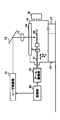
図1は、従来のアニール装置の一構成例を示す図である。
【0006】
図1のアニール装置は、レーザ発振器11と、反射ミラー12と、集光レンズ13と、チャンバ14と、架台15と、ガス導入装置16と、ガス排出装置17と、石英ガラス18と、アーム駆動部19と、制御部20とを有するよう構成されている。また、アーム駆動部にはアーム21が具備されている。
【0007】
図1において、レーザ発振器11よりレーザ光(例えば、エキシマレーザ光)が出射されると、反射ミラー12は、レーザ光を集光レンズ13側へと反射させる。集光レンズ13は、入力されたレーザ光を集光し、固定された架台15の上に設置されたチャンバ14へ照射させる。チャンバ14に照射されたレーザ光は、石英ガラス18を通過しアーム駆動部19からのアーム21により支持されている加工対象物22に対して照射される。アーム駆動部19は、レーザ光の照射軸に対して前後左右方向(X,Y方向)への移動が行えると共に照射軸に対して傾斜角θ分傾かせることができる。これにより、加工対象物22は、アーム21によりチャンバ14内で様々な方向に移動されアニール処理等の表面改質処理が行われる。
【0008】
なお、チャンバ14内には、ガス導入装置16により導入管から窒素等のアニール雰囲気(不活性ガス)が流入され、チャンバ14内を真空にする場合は、ガス排出装置17により気体の排出が行われる。
【0009】
また、集光レンズ13は、光学系ビームホモジナイザ(以下、ホモジナイザという。)でもよく、ホモジナイザを用いることでビームの強度分布が均一化(ホモジナイズ)され、加工対象物22の加工面に照射されるため、精度の高いアニール処理を行うことができる。
【0010】
また、制御部20は、レーザ発振器11からのレーザ光の発振タイミングと、ガス導入装置16からの不活性ガスの導入タイミングと、ガス排出装置17の排出タイミングと、アーム駆動部19の駆動のタイミングとを制御する。
【0011】
上述したアニール装置により、加工対象物22のアニール処理や表面改質処理等の加工を行うことができる。
【0012】
【発明が解決しようとする課題】
しかしながら、図1で示した従来のアニール装置は、チャンバ14内で、アーム21を移動させるため、チャンバ14自体を予め大きくしておく必要がある。そのため、場所の設置スペースをある程度大きめに確保しなければならない。また、チャンバ14内の空間(体積)が大きくなることで窒素等の不活性ガスの導入量も多くなり、更に、加工対象物22の交換時には、チャンバ14内の雰囲気を外気(大気雰囲気)に戻す必要があるが、加工対象物22を交換する度に不活性ガスを充満させるまでの時間もかかるため、アニール処理等の処理時間を大幅に費やしてしまう。
【0013】
また、チャンバ14内部に収納されるアーム21等の機構部についても、チャンバ14内の雰囲気を大気から窒素等の不活性ガスに置換し、維持するための真空対応した機器類を使用する必要があるため、装置コストが膨大になってしまう。
【0014】
本発明は、上述した問題点に鑑みなされたものであり、アニール装置を小型化、省スペース化を可能にして効率的なアニール処理を行うことができるアニール装置及びアニール方法を提供することを目的とする。
【0015】
【課題を解決するための手段】
上記課題を解決するために、本件発明は、以下の特徴を有する課題を解決するための手段を採用している。
【0016】
請求項1に記載された発明は、外部から入射するレーザ光により、処理室内に設けた加工対象物のアニールを行うアニール装置において、前記処理室を移動する移動手段を設け、該移動手段により前記処理室を移動させて均一なアニールを行うことを特徴とする。
【0017】
請求項1記載の発明によれば、処理室の外部から入射されるレーザ光に対して、加工対象物が固定された処理室を移動させることができるため、該加工対象物に均一なアニール処理を行うことができる。
【0018】
請求項2に記載された発明は、前記処理室は、前記加工対象物とほぼ同等の大きさを有する空間とすることを特徴とする特徴とする。
【0019】
請求項2記載の発明によれば、処理室を小型化させて、アニール処理を行うことができる。処理室を小型化させたことにより処理室内のガスの導入、排出時間も削減することができ、作業効率を向上させることができる。
【0020】
請求項3に記載された発明は、前記処理室は、スリット状の開口部を有していることを特徴とする特徴とする。
【0021】
請求項3記載の発明によれば、加工対象物が処理室内に搬出入に必要だけの大きさを持つスリット状の開口部にすることで、外気(大気雰囲気)の処理室内への流入を減少させることができる。
【0022】
請求項4に記載された発明は、前記移動手段は、X−Y−θステージであることを特徴とする特徴とする。
【0023】
請求項4記載の発明によれば、処理室に加工対象物を固定支持させることで、該加工対象物のどの加工位置に対しても多種の加工を行うことができる。
【0024】
請求項5に記載された発明は、外部から入射するレーザ光により、処理室内に設けた加工対象物の加工を行うアニール方法において、前記処理室を移動させて均一なアニールを行うことを特徴とする特徴とする。
【0025】
請求項5記載の発明によれば、処理室の外部から入射されるレーザ光に対して、加工対象物が固定された処理室を移動させることができるため、該加工対象物に均一なアニール処理を行うことができる。
【0026】
請求項6に記載された発明は、前記処理室は、開口部を有し、前記開口部が開口している間は、処理室内に外気と異なる雰囲気を導入させることを特徴とする。
【0027】
請求項6記載の発明によれば、処理室内の雰囲気を安定させることができるため、アニール処理効率も向上させることができ、また、アニール処理精度を向上させることができる。
【0028】
【発明の実施の形態】
本発明は、アニール装置を小型化、及び省スペース化するため、処理室(チャンバ)の大きさを加工対象物だけの搬出入及び固定支持できる最小限の大きさとし、また、処理室をXY方向及びθ方向への移動が可能な駆動装置上に設置し、処理室内に加工対象物を固定支持させることで、レーザ発振器からのレーザ光に対して処理室ごと移動させて加工を行う。これにより、処理室を小型化、省スペース化することができる。
【0029】
また、加工対象物の入れ替え(搬出入)は、処理室の外部に搬送装置を設けることで対応する。なお、加工対象物の搬出入は、処理室の片面に加工対象物を搬出入させるための搬送装置のアーム(ハンド)が出入り可能なスリット状の形状面(以下、スリット形状面という。)を備え、加工対象物の搬出入時には、ガス導入装置が処理室内へ不活性ガスを導入し続けることにより、処理室内への大気雰囲気の流入を防ぐことができる。
【0030】
次に、本発明におけるアニール装置の実施の形態について、図を用いて説明する。
【0031】
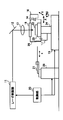
図2は、本発明におけるアニール装置の一構成例の図である。
【0032】
図2のアニール装置は、レーザ発振器11と、反射ミラー12と、集光レンズ13と、チャンバ14と、架台15と、ガス導入装置16と、ガス排出装置17と、石英ガラス18と、制御部20と、アーム21と、固定支持部23と、駆動装置24と、搬送装置25とを有するよう構成されている。また、チャンバ14にはスリット形状面26を備えている。
【0033】
図2において、まず、レーザ発振器11より、レーザ光(例えば、エキシマレーザ光)が出射されると、反射ミラー12は、レーザ光を集光レンズ13側へと反射させる。集光レンズ13は、入力されたレーザ光を集光し、駆動装置24上に設置されたチャンバ14へ照射される。チャンバ14へ照射されたレーザ光は、石英ガラス18を通過し、固定支持部23上に固定された加工対象物22へ照射することで、表面改質処理等のアニール処理を行うことができる。
【0034】
ここで、固定支持部23に載置された加工対象物22の移動は、固定された架台15上に設置された駆動装置24に用いて行うことができる。駆動装置24は、X−Y−θテーブルであり、集光レンズ13からのレーザ光の照射軸に対して前後左右方向(X方向、Y方向)への移動が可能であり、かつ駆動装置24を照射軸に対してθ分回転させることができる。このように駆動装置24を駆動させることで、難易度の高い多種のアニール処理、表面改質処理等の加工を行うことができる。
【0035】
次に、加工対象物22をチャンバ14から搬出入する場合の動作について説明する。図2のアニール装置においては、搬送装置25と、アーム21が設置されている。また、チャンバ14の片面(搬送装置側)には、スリット形状面26が形成されている。スリットの大きさは、アーム21が加工対象物22を搬出入可能な大きさになっている。なお、スリット形状面26は、搬出入以外の時(加工時)にはスリット状の開口部が閉じるため、チャンバ14内が密閉された状態になる。
【0036】
ここで、本発明におけるスリット面について、具体的に図を用いて説明する。
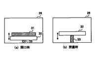
【0037】
図3は、本発明におけるスリット面の一例を示す図である。図3のスリット形状面26は、スリット開口部31と、扉32と、駆動部33とを有し、駆動部33は、扉32を上下動させることができるため、スリット開口部31の開閉を加工対象物22の搬出入時のみ行うようにすることができる。駆動部33は、スリット開口部31が開口時には、図3(a)に示すような位置に扉32を移動させ、スリット開口部を閉塞する場合には、図3(b)に示すような位置にスリット扉32を移動させることで開口部31が閉じた状態になりチャンバ14内が密閉される。なお、駆動部33の動作は制御部20にて行う。
【0038】
搬送装置25は、アーム21をX方向に駆動させることにより、チャンバ14内にある加工対象物22を捕捉し、チャンバ14の内外への移動を行う。なお、加工対象物22の搬出入を行う際には、上述したようにアームを駆動させてもよく、また、チャンバ14をアーム21の方向(X方向)へ移動させることにより加工対象物22の搬出入を行ってもよい。
【0039】
また、ガス導入装置16は、導入管からチャンバ14内に窒素ガス等の不活性ガスを導入し、ガス排出装置17は、チャンバ14内の気体の排出を行う。これにより、チャンバ14内を真空にさせることができ、高精度なアニール処理を行うことができる。なお、スリット開口部31が開いている場合は、外気(大気雰囲気)がチャンバ14内に流入しないように、ガス導入装置16から導入管を通して窒素ガス等の不活性ガスを随時導入させ、外気の流入を防いでいる。
【0040】
また、上述したアニール装置は発明の範囲においてこの限りではなく、例えば、石英ガラス18もチャンバ14内を密閉状態にしたままレーザ光を通過することができる物質であればよい。更に、集光レンズ13の替わりにホモジナイザを用いてもよい。また、加工対象物には、半導体に使用するウエハーやガラス素材等が用いられ、本発明により、アニール処理等の高度な加工を行うことができる。
【0041】
また、制御部20は、レーザ発振器11からのレーザ光の発振タイミングと、ガス導入装置16からの不活性ガスの導入タイミングと、ガス排出装置17の排出タイミングと、駆動装置24、搬送装置25、アーム21、及び駆動部33の駆動タイミングとを制御する。
【0042】
上述したように本発明によれば、処理室(チャンバ)を駆動装置上に設置し、また、加工対象物の交換を行うための搬送装置を該処理室の外に設けることで、処理室を小型化、省スペース化することができる。また、処理室内を省スペース化させることにより、窒素等の不活性ガスの充満を早期に実現でき、加工処理効率を向上させることができる。また、アニール装置自体も小型化させることができる。
【0043】
なお、本発明における加工内容はこの限りではなく、多種の表面改質処理や、穴開け又は溶接等の加工処理も行うことができる。また、アニール装置における処理室の数及び搬送装置の数は上述の限りではなく、複数の装置構成にすることで、処理効率を更に速めることができる。
【0044】
【発明の効果】
本発明によれば、処理室を駆動装置上に設置し、また、加工対象物の交換を行うための搬送装置を該処理室の外に設けることで、処理室及びアニール装置を小型化、省スペース化することができる。また、処理室内を省スペース化させることにより、窒素等の不活性ガスの充満を早期に実現でき、加工処理効率を向上させることができる。
【図面の簡単な説明】
【図1】従来におけるアニール装置の一構成例を示す図である。
【図2】本発明におけるアニール装置の一構成例を示す図である。
【図3】本発明におけるスリット面の一例を示す図である。
【符号の説明】
11 レーザ発振器
12 反射ミラー
13 集光レンズ
14 チャンバ
15 架台
16 ガス導入装置
17 ガス排出装置
18 石英ガラス
19 アーム駆動部
20 制御部
21 アーム
22 加工対象物
23 固定支持部
24 駆動装置
25 搬送装置
26 スリット形状面
31 スリット開口部
32 扉
33 駆動部[0001]
TECHNICAL FIELD OF THE INVENTION
The present invention relates to an annealing device and an annealing method.
[0002]
[Prior art]
2. Description of the Related Art In recent years, a processing target such as a semiconductor is processed using a CO 2 laser beam, a YAG laser beam, or the like. A laser beam is mainly used for processing such as welding, cutting, and drilling using a high energy density by narrowing a beam spot diameter for irradiation on a processing surface of a processing object. Further, as another method, a so-called surface modification treatment for improving the surface function of a material while melting only a limited region of the material surface by setting the beam spot diameter to a relatively large value (1 to several mm) may be used. It is being used.
[0003]
In the case of performing the surface modification treatment described above, the treatment is generally performed using a treatment chamber such as a chamber having an atmosphere different from the outside air (atmosphere). By introducing an inert gas into the treatment chamber, increasing the temperature, or giving light, electricity, magnetism, or the like, various kinds of surface modification reactions can be caused.
[0004]
For example, when annealing a relatively large substrate such as a liquid crystal substrate, a processing chamber for maintaining an annealing atmosphere such as nitrogen is provided, and the processing chamber includes not only a substrate fixing mechanism but also XY A mechanism for moving a substrate such as a stage, and an annealing apparatus accommodating a set of transfer / transport devices are generally used. The annealing apparatus performs an annealing process by moving a processing target in various directions in the chamber while irradiating a laser beam.
Here, the above contents will be described with reference to the drawings.
[0005]
FIG. 1 is a diagram showing one configuration example of a conventional annealing apparatus.
[0006]
1 includes a
[0007]
In FIG. 1, when laser light (for example, excimer laser light) is emitted from a
[0008]
Note that an annealing atmosphere (inert gas) such as nitrogen is introduced into the
[0009]
The
[0010]
Further, the
[0011]
With the above-described annealing apparatus, processing such as annealing and surface modification of the
[0012]
[Problems to be solved by the invention]
However, in the conventional annealing apparatus shown in FIG. 1, the
[0013]
Also, for the mechanical units such as the
[0014]
The present invention has been made in view of the above-described problems, and has as its object to provide an annealing apparatus and an annealing method capable of performing an efficient annealing process by enabling the annealing apparatus to be reduced in size and space. And
[0015]
[Means for Solving the Problems]
In order to solve the above problems, the present invention employs means for solving the problems having the following features.
[0016]
According to a first aspect of the present invention, there is provided an annealing apparatus for annealing a processing object provided in a processing chamber by a laser beam incident from the outside, wherein a moving means for moving the processing chamber is provided, and It is characterized in that uniform annealing is performed by moving the processing chamber.
[0017]
According to the first aspect of the present invention, since the processing chamber in which the processing target is fixed can be moved with respect to the laser beam incident from outside the processing chamber, the processing target can be uniformly annealed. It can be performed.
[0018]
The invention described in
[0019]
According to the second aspect of the present invention, the annealing can be performed by reducing the size of the processing chamber. By reducing the size of the processing chamber, the time for introducing and discharging the gas in the processing chamber can be reduced, and the working efficiency can be improved.
[0020]
The invention described in claim 3 is characterized in that the processing chamber has a slit-shaped opening.
[0021]
According to the third aspect of the present invention, the processing object is formed into a slit-shaped opening having a size necessary for carrying in and out of the processing chamber, so that the outside air (atmospheric atmosphere) flows into the processing chamber. Can be done.
[0022]
The invention described in claim 4 is characterized in that the moving means is an XY-θ stage.
[0023]
According to the fourth aspect of the present invention, the processing object is fixedly supported in the processing chamber, so that various types of processing can be performed at any processing position of the processing object.
[0024]
According to a fifth aspect of the present invention, in the annealing method for processing a workpiece provided in a processing chamber by a laser beam incident from the outside, the processing chamber is moved to perform uniform annealing. It is a feature to be.
[0025]
According to the fifth aspect of the present invention, since the processing chamber in which the processing target is fixed can be moved with respect to the laser beam incident from outside the processing chamber, the processing target can be uniformly annealed. It can be performed.
[0026]
The invention described in claim 6 is characterized in that the processing chamber has an opening, and an atmosphere different from outside air is introduced into the processing chamber while the opening is open.
[0027]
According to the invention of claim 6, since the atmosphere in the processing chamber can be stabilized, the annealing process efficiency can be improved, and the annealing process accuracy can be improved.
[0028]
BEST MODE FOR CARRYING OUT THE INVENTION
According to the present invention, in order to reduce the size and space of the annealing apparatus, the size of the processing chamber (chamber) is set to the minimum size capable of carrying in / out only the object to be processed and fixedly supported. And a processing device that is mounted on a drive device that can move in the θ direction and fixedly supports an object to be processed in the processing chamber. Thus, the processing chamber can be reduced in size and space.
[0029]
In addition, replacement (transportation) of the processing object is handled by providing a transfer device outside the processing chamber. Note that the loading and unloading of the processing target is performed on a slit-shaped surface (hereinafter, referred to as a slit-shaped surface) through which an arm (hand) of a transfer device for transferring the processing target into and out of one side of the processing chamber can enter and exit. In addition, when the processing object is carried in and out, the gas introduction device keeps introducing the inert gas into the processing chamber, so that the air atmosphere can be prevented from flowing into the processing chamber.
[0030]
Next, an embodiment of the annealing apparatus according to the present invention will be described with reference to the drawings.
[0031]
FIG. 2 is a diagram of a configuration example of the annealing apparatus according to the present invention.
[0032]
2 includes a
[0033]
In FIG. 2, first, when laser light (for example, excimer laser light) is emitted from the
[0034]
Here, the movement of the
[0035]
Next, an operation when the
[0036]
Here, the slit surface in the present invention will be specifically described with reference to the drawings.
[0037]
FIG. 3 is a diagram illustrating an example of the slit surface according to the present invention. The slit-shaped
[0038]
The
[0039]
Further, the
[0040]
The above-described annealing apparatus is not limited to this in the scope of the invention. For example, the
[0041]
Further, the
[0042]
As described above, according to the present invention, a processing chamber (chamber) is installed on a drive device, and a transfer device for exchanging a workpiece is provided outside the processing chamber, so that the processing chamber is formed. It is possible to reduce the size and space. In addition, by reducing the space in the processing chamber, the filling of an inert gas such as nitrogen can be realized at an early stage, and the processing efficiency can be improved. Further, the size of the annealing apparatus itself can be reduced.
[0043]
The processing content in the present invention is not limited to this, and various types of surface modification processing, processing processing such as drilling or welding can be performed. The number of processing chambers and the number of transfer devices in the annealing device are not limited to those described above, and the processing efficiency can be further increased by using a plurality of device configurations.
[0044]
【The invention's effect】
According to the present invention, the processing chamber is installed on the driving device, and the transfer device for exchanging the workpiece is provided outside the processing chamber, so that the processing chamber and the annealing device can be reduced in size and saved. Space can be used. In addition, by reducing the space in the processing chamber, the filling of an inert gas such as nitrogen can be realized at an early stage, and the processing efficiency can be improved.
[Brief description of the drawings]
FIG. 1 is a diagram showing a configuration example of a conventional annealing apparatus.
FIG. 2 is a diagram showing one configuration example of an annealing apparatus according to the present invention.
FIG. 3 is a diagram illustrating an example of a slit surface according to the present invention.
[Explanation of symbols]
DESCRIPTION OF
Claims (6)
前記処理室を移動する移動手段を設け、該移動手段により前記処理室を移動させて均一なアニールを行うことを特徴とするアニール装置。In an annealing apparatus that anneals a processing target provided in a processing chamber by a laser beam incident from the outside,
An annealing apparatus, comprising: moving means for moving the processing chamber, wherein the moving means moves the processing chamber to perform uniform annealing.
前記加工対象物とほぼ同等の大きさを有する空間とすることを特徴とする請求項1に記載のアニール装置。The processing chamber is
2. The annealing apparatus according to claim 1, wherein the space has a size substantially equal to that of the processing target.
スリット状の開口部を有していることを特徴とする請求項1又は2に記載のアニール装置。The processing chamber is
The annealing apparatus according to claim 1, further comprising a slit-shaped opening.
X−Y−θステージであることを特徴とする請求項1乃至3の何れか一項に記載のアニール装置。The moving means,
The annealing apparatus according to any one of claims 1 to 3, wherein the annealing apparatus is an XY-θ stage.
前記処理室を移動させて均一なアニールを行うことを特徴とするアニール方法。In an annealing method for processing a processing object provided in a processing chamber by laser light incident from the outside,
An annealing method, wherein the processing chamber is moved to perform uniform annealing.
前記開口部が開口している間は、処理室内に外気と異なる雰囲気を導入させることを特徴とする請求項5に記載のアニール方法。The processing chamber has an opening,
The annealing method according to claim 5, wherein an atmosphere different from outside air is introduced into the processing chamber while the opening is open.
Priority Applications (1)
| Application Number | Priority Date | Filing Date | Title |
|---|---|---|---|
| JP2002165845A JP2004014792A (en) | 2002-06-06 | 2002-06-06 | Annealing apparatus and annealing method |
Applications Claiming Priority (1)
| Application Number | Priority Date | Filing Date | Title |
|---|---|---|---|
| JP2002165845A JP2004014792A (en) | 2002-06-06 | 2002-06-06 | Annealing apparatus and annealing method |
Publications (1)
| Publication Number | Publication Date |
|---|---|
| JP2004014792A true JP2004014792A (en) | 2004-01-15 |
Family
ID=30433588
Family Applications (1)
| Application Number | Title | Priority Date | Filing Date |
|---|---|---|---|
| JP2002165845A Pending JP2004014792A (en) | 2002-06-06 | 2002-06-06 | Annealing apparatus and annealing method |
Country Status (1)
| Country | Link |
|---|---|
| JP (1) | JP2004014792A (en) |
-
2002
- 2002-06-06 JP JP2002165845A patent/JP2004014792A/en active Pending
Similar Documents
| Publication | Publication Date | Title |
|---|---|---|
| US7902052B2 (en) | System and process for processing a plurality of semiconductor thin films which are crystallized using sequential lateral solidification techniques | |
| US8163129B2 (en) | Method and apparatus for cleaning a substrate | |
| JP2002532897A (en) | Gas-driven rotary susceptor for rapid thermal processing (RTP) systems | |
| WO2008080099A2 (en) | Laser optical system | |
| JP2003224067A (en) | Lithographic apparatus, apparatus cleaning method, device manufacturing method, and device manufactured by the method | |
| CN111247626B (en) | Laser irradiation method and laser irradiation system | |
| US20120225568A1 (en) | Annealing method and annealing apparatus | |
| JP2012186304A (en) | Substrate processing apparatus and substrate processing method | |
| KR101704843B1 (en) | Coating apparatus, coating method and storage medium | |
| JP2008128567A (en) | Substrate drying method and substrate drying apparatus | |
| TWI918896B (en) | Substrate processing apparatus and substrate processing method | |
| JP2008226991A (en) | Plasma processing equipment | |
| JP2002015970A (en) | Exposure method and exposure apparatus | |
| JP2000343257A (en) | Return light removal method and apparatus | |
| KR102825589B1 (en) | Substrate processing apparatus, substrate processing method, and storage medium | |
| JP2001284281A (en) | Laser processing apparatus and method | |
| JPH11340160A (en) | Laser annealing apparatus and method | |
| JP3219925B2 (en) | Peripheral exposure apparatus and peripheral exposure method | |
| JPH09139356A (en) | Laser annealing equipment | |
| CN112526827B (en) | Exposure device | |
| US11924955B2 (en) | Extreme ultraviolet light generation apparatus and electronic device manufacturing method | |
| JP2001028346A (en) | Shutter mechanism and control method for precision irradiation | |
| KR100338146B1 (en) | Laser annealing apparatus | |
| US20260054324A1 (en) | Substrate processing method and substrate processing apparatus | |
| JP7474579B2 (en) | Laser processing device and laser beam profile measuring method |
Legal Events
| Date | Code | Title | Description |
|---|---|---|---|
| A621 | Written request for application examination |
Free format text: JAPANESE INTERMEDIATE CODE: A621 Effective date: 20040910 |
|
| A977 | Report on retrieval |
Free format text: JAPANESE INTERMEDIATE CODE: A971007 Effective date: 20050530 |
|
| A131 | Notification of reasons for refusal |
Free format text: JAPANESE INTERMEDIATE CODE: A131 Effective date: 20050607 |
|
| A02 | Decision of refusal |
Free format text: JAPANESE INTERMEDIATE CODE: A02 Effective date: 20051011 |