JP2004010257A - Paper post processing device - Google Patents
Paper post processing device Download PDFInfo
- Publication number
- JP2004010257A JP2004010257A JP2002165905A JP2002165905A JP2004010257A JP 2004010257 A JP2004010257 A JP 2004010257A JP 2002165905 A JP2002165905 A JP 2002165905A JP 2002165905 A JP2002165905 A JP 2002165905A JP 2004010257 A JP2004010257 A JP 2004010257A
- Authority
- JP
- Japan
- Prior art keywords
- sheet
- cover
- paper
- width
- unit
- Prior art date
- Legal status (The legal status is an assumption and is not a legal conclusion. Google has not performed a legal analysis and makes no representation as to the accuracy of the status listed.)
- Pending
Links
Images


Landscapes
- Pile Receivers (AREA)
- Folding Of Thin Sheet-Like Materials, Special Discharging Devices, And Others (AREA)
Abstract
Description
【0001】
【発明の属する技術分野】
本発明は、電子写真複写機、プリンタ、ファクシミリ、及びこれらの機能を有する複合機等の画像形成装置から画像形成後に排出される記録用紙を順次、用紙後処理装置内に取り込み、この記録用紙に綴じ処理等の後処理を行うとともに、表紙給紙部に収容された表紙用紙を用紙載置台上に搬送する用紙後処理装置に関するものである。
【0002】
【従来の技術】
画像形成装置より排紙される画像記録済の複数枚の用紙を、コピー部数ごとに丁合して綴じ手段により綴じ合わせる用紙後処理装置が従来から知られている。
【0003】
この用紙後処理装置は、複写機やプリンタ等の画像形成装置本体と機能が接続されていて、コピーまたはプリントプロセスのシーケンス作動に対応して駆動する。
【0004】
表紙給紙部を備えた従来の用紙後処理装置において、表紙給紙部の給紙台上に載置される各種サイズの表紙用紙の幅方向を規制する可動の幅整合板が配置されている。各種サイズの表紙用紙を給紙台上にセットする際には、両側の整合板、又は一方の整合板を用紙幅より広い位置に予め拡げた後、表紙用紙を給紙台上の整合板間にセットし、整合板を手動させて表紙用紙の幅方向の側端部に当接させ、位置決めしていた。
【0005】
【発明が解決しようとする課題】
表紙給紙部は、通常の身長の人が立っている状態で表紙用紙の挿入、幅整合の操作をするように、用紙後処理装置の上部に配置されている。
【0006】
用紙後処理装置を、車椅子の人や身体障害者や大量のコピー作業をするため椅子に腰掛けたまま作業する人などが使用する場合に、用紙後処理装置の上部に配置された表紙給紙部において、幅整合の操作を行う事は困難であった。
【0007】
【課題を解決するための手段】
上記の課題は下記の用紙後処理装置により解決される。
【0008】
用紙後処理装置の上部に配置された表紙給紙部に収容された表紙用紙を用紙載置台上に搬送するとともに、画像形成装置から排出される記録用紙を前記用紙載置台上に積載して整合し、後処理する用紙後処理装置において、前記表紙給紙部の給紙皿上に載置される最大サイズの表紙用紙の幅より広い幅間隔を有する固定案内部、前記用紙載置台上に積載される用紙の幅方向を位置決めする幅整合板、前記幅整合板を移動可能に駆動する駆動手段、前記駆動手段を制御する制御手段、とを有し、前記表紙用紙を前記用紙載置台上に導入する時に、前記制御手段は、前記幅整合板を前記固定案内部の幅間隔より広く設定された間隔の待機位置に移動させるように制御することを特徴とする用紙後処理装置。
【0009】
【発明の実施の形態】
次に、本発明の用紙後処理装置の実施の形態を図面に基づいて説明する。
【0010】
[画像形成装置]
図1は画像形成装置A、画像読み取り装置B、用紙後処理装置(以下、後処理装置と称す)Cから成る画像形成システムの全体構成図である。図2は画像形成システムの外観斜視図である。
【0011】
画像形成装置Aは、回転する像担持体1の周囲に、帯電手段2、像露光手段(書き込み手段)3、現像手段4、転写手段5A、除電手段5B、及びクリーニング手段6を配置した画像形成手段を有する。画像形成手段は、帯電手段2によって像担持体1の表面に一様帯電を行った後に、像露光手段3のレーザビームによって原稿から読み取られた画像データに基づく露光走査を行って潜像を形成し、該潜像を現像手段4により反転現像して像担持体1の表面にトナー像を形成する。
【0012】
用紙収納部7Aから給紙された記録用紙(以下、用紙と称す)Sは転写位置へと送られる。転写位置において転写手段5Aにより前記トナー像が用紙S上に転写される。その後に、用紙Sは除電手段5Bにより裏面の電荷が消去されて像担持体1から分離され、搬送部7Bにより搬送され、引き続き定着手段8により加熱定着され、排紙ローラ7Cから排出される。
【0013】
用紙Sの両面に画像形成を行う場合には、定着手段8により加熱定着された用紙Sを、搬送路切り替え板7Dにより通常の排紙通路から分岐し、反転搬送部7Eにおいてスイッチバックして表裏反転した後、再び画像形成部を通過し、用紙Sの裏面に画像を形成し、定着手段8を経て、排紙ローラ7Cから装置外に排出される。排紙ローラ7Cから排出された用紙Sは、後処理装置Cの受入部11に送り込まれる。
【0014】
像担持体1の画像処理後の表面は、クリーニング手段6により表面に残留している現像剤が除去され、次の画像形成に備える。
【0015】
画像形成装置Aの上部には、原稿移動型読み取り方式の自動原稿送り装置を備えた画像読み取り装置Bが設置されている。
【0016】
画像形成装置Aの上部前面側には、画像形成モード、平綴じや中綴じ等の後処理モードを選択して設定する操作部9が配置されている。
【0017】
[後処理装置]
画像形成装置Aに接続する後処理装置Cは、入口搬送部10、シフト処理部20、綴じ処理部30、綴じ手段(ステイプル手段)40、表紙給紙部50、中折り処理部60、及び排紙部70とから構成されている。
【0018】
入口搬送部10は画像形成装置Aから排出された用紙Sを各処理部に搬送する。シフト処理部20は入口搬送部10から搬送された用紙Sをシフト処理区分けして後述の昇降排紙台72に排出する。綴じ処理部30は入口搬送部10から搬送された用紙Sを積載して、後述の綴じ手段40により、中綴じ処理又は平綴じ処理を行う。中折り処理部60は用紙Sの用紙搬送方向中央部を折り曲げ中折り処理を行い、後述の下部排紙台73に排出する。表紙給紙部50は表紙用紙(以下、表紙と称す)Kを給紙してシフト処理部20または綴じ処理部30に搬送する。
【0019】
排紙部70は、画像形成装置Aから排出された用紙Sを入口搬送部10を経由して後処理を行わず直接排紙して収容する上部排紙台71と、シフト処理または平綴じ処理された用紙束Saを収容する昇降排紙台72と、中折り処理された用紙束Saを収容する下部排紙台73を有する。
【0020】
・後処理装置の用紙搬送経路
図3は後処理装置Cの用紙搬送経路を示す模式図である。
【0021】
後処理装置Cは画像形成装置Aから搬出された用紙Sの受入部11が画像形成装置Aの排紙ローラ7Cと合致するよう位置と高さを調節して設置されている。
【0022】
受入部11の入口部ローラ12の用紙搬送方向下流に接続する用紙Sの搬送路は、上段の第1搬送路▲1▼と中段の第2搬送路▲2▼及び下段の第3搬送路▲3▼の3系統に分岐されていて、切換手段G1,G2の占める角度の選択により用紙Sが何れかの搬送路に給送されるようになっている。
【0023】
・上部排紙台71に排紙
画像形成装置Aから排出された画像形成済みの用紙Sは、受入部11に導入され、入口部ローラ12により搬送されて、上方の第1の切換手段G1の右方の通路13を通過して、上方の搬送ローラ対14に挟持、搬送され、更に搬送ローラ15により挟持、搬送された後、排紙ローラ16に挟持されて機外上部の上部排紙台71上に排出され、順次積載される(第1搬送路▲1▼)。
【0024】
この用紙搬送過程では、切換手段G1はソレノイドSD1の駆動により揺動され、通路17を閉止し、通路13を開放状態にして、用紙Sの上部排紙台71への通過を可能にする。
【0025】
この上部排紙台71には最大約200枚の用紙Sを収容することが可能であり、操作者は後処理装置Cの上部から容易に取り出すことができる。
【0026】
・シフト処理又はノンソート
この搬送モードに設定されると、切換手段G1はソレノイドSD1がオフの状態で、通路13を閉止し、通路17を開放状態に保持し、用紙Sの通路17の通過を可能にする。
【0027】
画像形成装置Aから排出された画像形成済みの用紙Sは、受入部11、入口部ローラ12を通過し、切換手段G1の下方に開放状態に形成された通路17を通過して、搬送ローラ18に挟持されて、第2搬送路▲2▼である斜め下方の第2の切換手段G2の上方の通路21を通過して、搬送ローラ22に挟持され、通路23を経て、搬送ローラ(シフトローラ)24に挟持され、排紙ローラ26により機外の昇降排紙台72上に排出、載置される(第2搬送路▲2▼)。
【0028】
この昇降排紙台72には最大約3000枚の用紙Sを収容することが可能である。
【0029】
・平綴じ処理
画像形成装置A内で画像形成処理されて、後処理装置Cの受入部11に送り込まれた画像形成済みの用紙Sは、入口部ローラ12、第1の切換手段G1の下方の通路17を通過して、搬送ローラ18に挟持されて、第3搬送路▲3▼に搬送される。
【0030】
第3搬送路▲3▼において、用紙Sは切換手段G2の下方の通路31を通過して、下流の搬送ローラ32により挟持、搬送される。用紙Sは、更に下流の搬送ローラ34により挟持されて送り出され、傾斜配置された第1用紙載置台(用紙載置台)35の上方空間に排出され、第1用紙載置台35または第1用紙載置台35上に積載された用紙Sの上面に接し、滑走上昇したのち、搬送ローラ34から用紙Sの進行方向後端部が排出されたのちには、用紙Sの自重により下降に転じ、第1用紙載置台35の傾斜面上を滑落し、綴じ手段40近傍の平綴じ用突き当て部材41の用紙突き当て面に用紙Sの進行方向先端部が当接して停止する。
【0031】
この停止位置において、第1用紙載置台35上に所定枚数の用紙Sが積載され、幅整合板36により幅整合され、綴じ手段40によって用紙束Saが綴じ合わされる。
【0032】
綴じ手段40は、第1用紙載置台35上に積載される用紙Sの下面側に位置し綴じ針SPを打ち込む打針機構部40Aと、用紙Sの上面側に位置し綴じ針SPを折り曲げる受針機構部40Bとの二分割構造に構成され、その中間に用紙Sが通過可能な通路42を形成している。
【0033】
綴じ手段40により綴じ処理された用紙束Saは、排出ベルト38の排出爪38aにより用紙束Saの後端部を保持されて、第1用紙載置台35の載置面上を滑走して斜め上方に押し上げられ、回転する排紙ローラ26に挟持されて、昇降排紙台72上に排出、積載される。
【0034】
図4(a)は、用紙Sの端面近傍で中央振り分け2箇所に綴じ針SPが打針された平綴じ用紙Sの平面図、図4(b)は、用紙Sのコーナ部近傍の1箇所に綴じ針SPが打針された端綴じ用紙Sの平面図である。
【0035】
・表紙給紙
表紙給紙部50は、給紙皿51、昇降底板52から成る表紙載置部と、送り出しローラ53、重送防止給紙ローラ54から成る表紙送り手段とから構成されている。
【0036】
表紙給紙部50の給紙皿51、昇降底板52に載置された表紙Kは、送り出しローラ53、重送防止給紙ローラ54から成る表紙送り手段により1枚ずつ給紙される。表紙Kは、第4搬走路▲4▼の通路55を通過して、搬送ローラ対14の挟持位置を通過し、通路19、搬送ローラ18を通過した後、第3搬送路▲3▼の通路31、搬送ローラ32、通路33、搬送ローラ34を経て、第1用紙載置台35上に到達する。
【0037】
・中綴じ処理
中綴じモードに設定されると、綴じ手段40の綴じ処理位置近傍の平綴じ用突き当て部材41が第5搬送路▲5▼から待避し、ほぼ同時にそれより下流の中綴じ用突き当て部材43が起動して通路42を遮断する。
【0038】
中綴じ用突き当て部材43は、設定された用紙Sのサイズ(搬送方向の長さ)に対応する所定位置に移動して停止する。
【0039】
最終の用紙Sが第1用紙載置台35上に位置決め載置された後、用紙束Saに綴じ手段40による中綴じ処理を行う。この中綴じ処理により、用紙Sの搬送方向の中央部に綴じ針SPが打ち込まれる。
【0040】
図4(c)は、用紙Sの長手方向中央振り分け2箇所に綴じ針SPが打針された中綴じ用紙Sの平面図である。
【0041】
・中折り処理
中綴じ処理後、中綴じ用突き当て部材43が揺動して、通路42の下流の通路を開放する。中綴じ処理された用紙束Saは、湾曲した通路と中間搬送ローラ61を通過して、斜め下方の搬送ベルト62上を案内板63に案内されて搬送され、更に、第2用紙載置台64上を下降して、可動突き当て手段65に用紙束Saの搬送方向の先端部が当接して、所定位置に停止する(第6搬送路▲6▼)。
【0042】
停止状態の用紙束Saの搬送方向の中央部、即ち中綴じ位置の斜め下方には、用紙突き出し手段66が設置されている。中綴じ位置の斜め上方には、中折りローラ67と、加圧ローラ68が設置されている。
【0043】
中折り開始信号により、用紙突き出し手段66が用紙束Saを介して従動回転する中折りローラ67の挟持部を押し広げて用紙束Saの中央部に折り目を形成する。折り目を形成された用紙束Saの中央部は、加圧ローラ68の挟持位置で折り目が更に強く圧迫され折り目が強化された後、機外の下部排紙台73上に排出される。
【0044】
図4(d)は、用紙Sと表紙Kとから成る用紙束Saに中綴じと中折りの後処理を施して作成された冊子の斜視図である。
【0045】
[表紙給紙部の給紙皿]
図5は、表紙給紙部50の平面図である。
【0046】
表紙Kを載置する給紙皿51の表紙給紙方向の先端部には、突き当て部51Aが立設されている。
【0047】
給紙皿51の表紙給紙方向に直交する用紙幅方向の両端部には、固定案内部51Bが立設されている。固定案内部51Bは手前側と奥側の二箇所に平行配置されている。固定案内部51Bの平行2平面間の幅方向の幅間隔W2は、最大サイズの表紙Kの幅W1より大きく形成されている(W2>W1)。例えば、A3判の表紙Kを載置可能にする表紙給紙部50の場合、固定案内部51Bの幅間隔W2は、A3判の幅寸法297mmより大きい寸法、例えば、約350mmに形成されている。したがって、固定案内部51Bの平行2平面間の幅間隔W2は、最大サイズの表紙Kを受け入れるのに充分な余裕を有する。
【0048】
操作者は、給紙皿51及び昇降底板52上に表紙Kを載置し、表紙Kの先端部を突き当て部51Aに突き当てて先端部整合する。表紙Kの幅方向を規制する従来の幅整合板は設けられていないから、幅整合板を予め表紙Kの幅寸法より広く拡張させて、表紙Kを載置したのち、幅整合板により表紙Kの幅整合を行う操作が不要となる。操作者は、余裕をもって形成された固定案内部51Bの平行2平面間に、表紙Kを載置するだけで済み、表紙Kを給紙皿51上に容易に載置する事ができる。
【0049】
したがって、車椅子の人や身体障害者や大量のコピー作業をするため椅子に腰掛けたまま作業する人などが使用する場合に、後処理装置Cの上部に配置された表紙給紙部50に表紙Kを楽に載置する事ができる。
【0050】
[綴じ処理部の用紙幅整合]
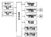
図6は綴じ処理部30の平面図である。図7は、後処理装置Cの制御を示すブロック図である。
【0051】
綴じ処理部30は、中綴じ処理時に用紙Sと表紙Kを通過可能にする通路42を介して上下に分離された打診機構部40Aと受針機構部40Bとで構成した2組の綴じ手段40と、用紙搬送方向に直交する方向の用紙幅方向を整合する上流側の幅整合板36及び下流側の幅整合板44と、用紙搬送方向の用紙先端部を規制する平綴じ用突き当て部材41及び中綴じ用突き当て部材43とから成る用紙先端部位置決め手段と、端綴じ処理及び中綴じ処理される用紙束Saを載置する第1用紙載置台35とにより構成したものである(図3参照)。
【0052】
図6の綴じ処理部30において、モータM1は2本の排出ベルト38を回動させ、モータM2は上流側の2個の幅整合板36を移動させ、モータM3は2個の綴じ手段40を移動させ、モータM4は下流側の2個の幅整合板44を移動させる。平綴じ用突き当て部材41、中綴じ用突き当て部材43は、図示しないモータにより揺動可能に駆動され、用紙Sの先端部位置決めと、用紙Sの通過とを可能にする。
【0053】
上流側の幅整合板36及び下流側の幅整合板44の待機位置の間隔W3は、表紙給紙部50の固定案内部51Bの幅間隔W2より広く設定される。従って、最大サイズの表紙Kの幅W1に対して、表紙給紙部50、綴じ処理部30において、W1<W2<W3となるように設定される。
【0054】
操作部9において、平綴じ処理が設定されると、表紙給紙部50の給紙皿51上に載置された表紙Kは、表紙送り手段、搬送手段により搬送され、第1用紙載置台35上に載置され、平綴じ用突き当て部材41に用紙Sの進行方向先端部が当接して停止する。第1用紙載置台35上に表紙Kが進入するに先立って、幅整合板36は表紙Kを受け入れるために、間隔W3の待機位置に待機する。
【0055】
制御手段90は、第1用紙載置台35上に表紙Kが載置される都度、幅整合板36をモータM2により駆動し、表紙Kの幅方向の中央側に移動させ、表紙Kの両側端部を押圧して幅整合を行う。第1用紙載置台35上に所定枚数の用紙Sが積載されて幅整合された後、綴じ手段40によって用紙束Saが平綴じ処理される。
【0056】
操作部9において、中綴じ処理が設定されると、表紙給紙部50の給紙皿51上に載置された表紙Kは、表紙送り手段、搬送手段により搬送され、第1用紙載置台35上に載置され、中綴じ用突き当て部材43に用紙Sの進行方向先端部が当接して停止する。第1用紙載置台35上に表紙Kが進入するに先立って、幅整合板36,44は表紙Kを受け入れるために、間隔W3の待機位置に待機する。
【0057】
制御手段90は、第1用紙載置台35上に表紙Kが載置される都度、上流側の幅整合板36をモータM2により駆動し、下流側の幅整合板44をモータM4により駆動させる。幅整合板36,44は、それぞれ表紙Kの幅方向の中央側に移動して、表紙Kの両側端部を押圧して幅整合を行う。第1用紙載置台35上に所定枚数の用紙Sが積載されて幅整合された後、綴じ手段40によって用紙束Saが中綴じ処理される。
【0058】
なお、後処理装置Cは、表紙給紙部50にインサート用紙を載置して、画像形成装置Aから排出された複数の用紙SやOHPシートの間に挿入する事も可能である。このインサート用紙挿入モードにおいても、表紙給紙部50、綴じ処理部30において、W1<W2<W3となるように設定する事により、操作者は給紙皿51上に用紙を容易に載置することができる。
【0059】
また、後処理装置Cは、表紙給紙部50に画像形成装置Aから直接排出された用紙S以外の用紙等を載置して、オフラインで綴じ処理、折り処理を実行させることも可能である。このオフライン処理においても、表紙給紙部50、綴じ処理部30において、W1<W2<W3となるように設定する事により、操作者は給紙皿51上に用紙を容易に載置することができる。
【0060】
前記幅整合板36,44は、第1用紙載置台35上にセンター基準で幅整合を行う後処理装置に限定されるものではなく、片側基準で幅整合を行う後処理装置にも適用可能である。
【0061】
なお、本発明の実施の形態では、複写機に接続した後処理装置Cを示したが、プリンタ、ファクシミリ等の画像形成装置や軽印刷機等と接続して使用する後処理装置にも適用可能である。
【0062】
【発明の効果】
以上説明したように、本発明の後処理装置により、以下の優れた効果が得られる。
【0063】
車椅子の人や身体障害者や大量のコピー作業をするため椅子に腰掛けたまま作業する人などが後処理装置を使用する場合に、後処理装置の上部に設置された表紙給紙部の給紙皿上に表紙又は用紙を、整合操作や目視確認をしないで、簡単に載置するのみで、後処理を行う事ができる。
【図面の簡単な説明】
【図1】画像形成装置、画像読み取り装置、後処理装置から成る画像形成システムの全体構成図。
【図2】画像形成システムの外観斜視図。
【図3】後処理装置の用紙搬送経路を示す模式図。
【図4】平綴じ用紙の平面図、端綴じ用紙の平面図、中綴じ用紙の平面図、及び中綴じと中折りの後処理を施して作成された冊子の斜視図。
【図5】表紙給紙部の平面図。
【図6】綴じ処理部の平面図。
【図7】後処理装置の制御を示すブロック図。
【符号の説明】
9 操作部
30 綴じ処理部
35 第1用紙載置台(用紙載置台)
36,44 幅整合板
40 綴じ手段(ステイプル手段)
41 平綴じ用突き当て部材
43 中綴じ用突き当て部材
50 表紙給紙部
51 給紙皿
51A 突き当て部
51B 固定案内部
90 制御手段
A 画像形成装置
C 用紙後処理装置(後処理装置)
K 表紙用紙(表紙)
S 記録用紙(用紙)
W1 最大サイズの表紙の幅
W2 固定案内部の幅間隔
W3 幅整合板の待機位置の間隔[0001]
TECHNICAL FIELD OF THE INVENTION
The present invention sequentially takes in recording paper discharged after image formation from an image forming apparatus such as an electrophotographic copying machine, a printer, a facsimile, and a multifunction peripheral having these functions into a paper post-processing apparatus, and applies the recording paper to the recording paper. The present invention relates to a sheet post-processing device that performs post-processing such as a binding process and conveys a cover sheet stored in a cover sheet feeding unit onto a sheet mounting table.
[0002]
[Prior art]
2. Description of the Related Art A sheet post-processing apparatus has been conventionally known in which a plurality of image-recorded sheets discharged from an image forming apparatus are collated and bound by a binding unit for each number of copies.
[0003]
The sheet post-processing apparatus is connected in function to an image forming apparatus main body such as a copying machine or a printer, and is driven in response to a sequence operation of a copy or print process.
[0004]
In a conventional sheet post-processing apparatus having a cover sheet feeding section, a movable width matching plate for regulating the width direction of cover sheets of various sizes placed on a sheet feeding table of the cover sheet feeding section is arranged. . When setting cover paper of various sizes on the paper feed tray, first spread the alignment plates on both sides or one of the alignment plates to a position wider than the paper width, and then put the cover paper between the alignment plates on the paper feed tray. And the alignment plate is manually operated to abut against the side edge of the cover sheet in the width direction to perform positioning.
[0005]
[Problems to be solved by the invention]
The cover sheet feeding unit is disposed above the sheet post-processing device so that the cover sheet is inserted and the width is adjusted while a normal-height person is standing.
[0006]
The cover paper feed unit located above the paper post-processing device when the paper post-processing device is used by people in wheelchairs, persons with physical disabilities, or those who work while sitting on a chair to perform a large amount of copying work. In this case, it was difficult to perform a width matching operation.
[0007]
[Means for Solving the Problems]
The above problems are solved by the following paper post-processing device.
[0008]
The cover sheet accommodated in the cover sheet feeding unit arranged at the top of the sheet post-processing device is transported onto the sheet placing table, and the recording sheets discharged from the image forming apparatus are stacked and aligned on the sheet placing table. In the sheet post-processing apparatus for performing post-processing, a fixed guide unit having a width interval wider than a width of a cover sheet of the maximum size placed on a sheet tray of the cover sheet feeding unit, and the sheet guide unit is loaded on the sheet placement table. A width adjusting plate for positioning the width direction of the sheet to be moved, a driving unit for movably driving the width aligning plate, a control unit for controlling the driving unit, and the cover sheet is placed on the sheet placing table. The paper post-processing apparatus according to claim 1, wherein the control unit controls the width adjusting plate to be moved to a standby position having a wider interval than the width of the fixed guide unit.
[0009]
BEST MODE FOR CARRYING OUT THE INVENTION
Next, an embodiment of a sheet post-processing apparatus of the present invention will be described with reference to the drawings.
[0010]
[Image forming apparatus]
FIG. 1 is an overall configuration diagram of an image forming system including an image forming apparatus A, an image reading apparatus B, and a sheet post-processing apparatus (hereinafter, referred to as a post-processing apparatus) C. FIG. 2 is an external perspective view of the image forming system.
[0011]
The image forming apparatus A is an image forming apparatus in which a charging unit 2, an image exposing unit (writing unit) 3, a developing unit 4, a transferring
[0012]
The recording paper (hereinafter, referred to as paper) S fed from the
[0013]
When performing image formation on both sides of the sheet S, the sheet S heated and fixed by the
[0014]
The developer remaining on the surface of the image carrier 1 after the image processing by the image processing is removed by the
[0015]
Above the image forming apparatus A, an image reading apparatus B provided with an automatic document feeder of a document moving type reading system is installed.
[0016]
On the upper front side of the image forming apparatus A, an
[0017]
[Post-processing device]
The post-processing apparatus C connected to the image forming apparatus A includes an
[0018]
The
[0019]
The
[0020]
FIG. 3 is a schematic diagram showing a paper transport path of the post-processing device C.
[0021]
The post-processing apparatus C is installed with its position and height adjusted so that the receiving
[0022]
The transport path of the sheet S connected downstream of the
[0023]
The image-formed sheet S discharged from the discharged image forming apparatus A to the
[0024]
In this sheet transporting process, the switching means G1 is swung by the driving of the solenoid SD1, closing the passage 17 and opening the
[0025]
The
[0026]
Shift processing or non-sort When this transport mode is set, the switching means G1 closes the
[0027]
The image-formed sheet S discharged from the image forming apparatus A passes through the receiving
[0028]
The elevating sheet discharge table 72 can accommodate a maximum of about 3000 sheets S.
[0029]
The image-formed paper S that has been subjected to the image forming processing in the side binding processing image forming apparatus A and sent to the receiving
[0030]
In the third transport path {circle around (3)}, the sheet S passes through a
[0031]
At this stop position, a predetermined number of sheets S are stacked on the first sheet placement table 35, width-aligned by the
[0032]
The binding means 40 includes a
[0033]
The sheet bundle Sa bound by the binding means 40 slides on the placing surface of the first sheet placing table 35 while the rear end portion of the sheet bundle Sa is held by the
[0034]
FIG. 4A is a plan view of a flat stapled sheet S in which binding needles SP are stapled at two places in the center near the end face of the sheet S, and FIG. FIG. 4 is a plan view of the edge binding paper S on which a binding staple SP is stapled.
[0035]
Cover Sheet Feeding The cover
[0036]
The cover sheet K placed on the
[0037]
When the saddle stitching mode is set, the
[0038]
The saddle
[0039]
After the final sheet S is positioned and placed on the first sheet placing table 35, the saddle stitching process by the binding
[0040]
FIG. 4C is a plan view of the saddle stitched sheet S in which the binding needles SP are stapled at two places in the center of the sheet S in the longitudinal direction.
[0041]
After the saddle stitching process, the saddle
[0042]
A
[0043]
In response to the center-folding start signal, the sheet protruding means 66 pushes and spreads the sandwiching portion of the center-folding
[0044]
FIG. 4D is a perspective view of a booklet created by performing post-processing of saddle stitching and folding in a sheet bundle Sa including a sheet S and a cover sheet K.
[0045]
[Paper tray of cover paper feeder]
FIG. 5 is a plan view of the cover
[0046]
An
[0047]
[0048]
The operator places the cover K on the
[0049]
Therefore, when used by a person in a wheelchair, a physically handicapped person, or a person who works while sitting on a chair to perform a large amount of copying work, the cover K is attached to the cover
[0050]
[Sheet width adjustment in binding section]
FIG. 6 is a plan view of the
[0051]
The binding
[0052]
6, the motor M1 rotates the two
[0053]
The interval W3 between the standby positions of the upstream
[0054]
When the flat binding process is set in the
[0055]
The control means 90 drives the
[0056]
When the saddle stitching process is set in the
[0057]
The
[0058]
Note that the post-processing apparatus C can also place an insert sheet on the cover
[0059]
Further, the post-processing apparatus C can also place a sheet other than the sheet S directly discharged from the image forming apparatus A on the cover
[0060]
The
[0061]
In the embodiment of the present invention, the post-processing apparatus C connected to a copying machine is shown, but the present invention can also be applied to a post-processing apparatus connected to an image forming apparatus such as a printer or a facsimile or a light printing machine. It is.
[0062]
【The invention's effect】
As described above, the following excellent effects can be obtained by the post-processing apparatus of the present invention.
[0063]
When a post-processing device is used by a person in a wheelchair, a physically handicapped person, or a person who works while sitting on a chair to perform a large amount of copying work, the cover paper feed unit installed above the post-processing device Post-processing can be performed simply by placing the cover or paper on the plate without performing any alignment operation or visual confirmation.
[Brief description of the drawings]
FIG. 1 is an overall configuration diagram of an image forming system including an image forming apparatus, an image reading apparatus, and a post-processing apparatus.
FIG. 2 is an external perspective view of the image forming system.
FIG. 3 is a schematic diagram illustrating a sheet conveyance path of the post-processing device.
FIG. 4 is a plan view of a flat stapled sheet, a plan view of an edge stapled sheet, a plan view of a saddle stitched sheet, and a perspective view of a booklet created by performing post-processing of saddle stitching and center folding.
FIG. 5 is a plan view of a cover sheet feeding unit.
FIG. 6 is a plan view of a binding processing unit.
FIG. 7 is a block diagram illustrating control of a post-processing device.
[Explanation of symbols]
9
36,44
41 abutment member for flat binding 43 abutment member for saddle stitching 50 cover
K cover paper (cover)
S Recording paper (paper)
W1 Width of cover sheet of maximum size W2 Width of fixed guide section W3 Interval of standby position of width matching plate
Claims (1)
前記表紙給紙部の給紙皿上に載置される最大サイズの表紙用紙の幅より広い幅間隔を有する固定案内部、
前記用紙載置台上に積載される用紙の幅方向を位置決めする幅整合板、
前記幅整合板を移動可能に駆動する駆動手段、
前記駆動手段を制御する制御手段、とを有し、
前記表紙用紙を前記用紙載置台上に導入する時に、前記制御手段は、前記幅整合板を前記固定案内部の幅間隔より広く設定された間隔の待機位置に移動させるように制御することを特徴とする用紙後処理装置。The cover sheet accommodated in the cover sheet feeding unit arranged at the top of the sheet post-processing device is transported onto the sheet placing table, and the recording sheets discharged from the image forming apparatus are stacked and aligned on the sheet placing table. In the paper post-processing device for post-processing,
A fixed guide unit having a width interval wider than the width of the maximum-size cover sheet placed on the sheet feeding tray of the cover sheet feeding unit;
A width alignment plate for positioning the width direction of the paper stacked on the paper mounting table,
Driving means for movably driving the width matching plate,
Control means for controlling the driving means,
When the cover sheet is introduced onto the sheet mounting table, the control unit controls the width alignment plate to be moved to a standby position at an interval set wider than the width interval of the fixed guide unit. Paper post-processing device.
Priority Applications (1)
| Application Number | Priority Date | Filing Date | Title |
|---|---|---|---|
| JP2002165905A JP2004010257A (en) | 2002-06-06 | 2002-06-06 | Paper post processing device |
Applications Claiming Priority (1)
| Application Number | Priority Date | Filing Date | Title |
|---|---|---|---|
| JP2002165905A JP2004010257A (en) | 2002-06-06 | 2002-06-06 | Paper post processing device |
Publications (1)
| Publication Number | Publication Date |
|---|---|
| JP2004010257A true JP2004010257A (en) | 2004-01-15 |
Family
ID=30433632
Family Applications (1)
| Application Number | Title | Priority Date | Filing Date |
|---|---|---|---|
| JP2002165905A Pending JP2004010257A (en) | 2002-06-06 | 2002-06-06 | Paper post processing device |
Country Status (1)
| Country | Link |
|---|---|
| JP (1) | JP2004010257A (en) |
Cited By (2)
| Publication number | Priority date | Publication date | Assignee | Title |
|---|---|---|---|---|
| JP2010269926A (en) * | 2009-05-25 | 2010-12-02 | Ricoh Co Ltd | Stacker and image forming system including the same |
| CN104589830A (en) * | 2014-12-29 | 2015-05-06 | 安徽华印机电股份有限公司 | Large-folio hemming-preventing book section conveying device used for page binding machine |
-
2002
- 2002-06-06 JP JP2002165905A patent/JP2004010257A/en active Pending
Cited By (2)
| Publication number | Priority date | Publication date | Assignee | Title |
|---|---|---|---|---|
| JP2010269926A (en) * | 2009-05-25 | 2010-12-02 | Ricoh Co Ltd | Stacker and image forming system including the same |
| CN104589830A (en) * | 2014-12-29 | 2015-05-06 | 安徽华印机电股份有限公司 | Large-folio hemming-preventing book section conveying device used for page binding machine |
Similar Documents
| Publication | Publication Date | Title |
|---|---|---|
| JP4000962B2 (en) | Paper post-processing device | |
| JP2002308521A (en) | Post-processing device and image forming device | |
| JP2004145200A (en) | Post-processing device | |
| JP2004010257A (en) | Paper post processing device | |
| JPH0513079B2 (en) | ||
| JP2003192213A (en) | Method and device for postprocessing paper | |
| JPS612671A (en) | Bookbinding apparatus in copying machine | |
| JP3882364B2 (en) | Sheet post-processing device | |
| JP3918459B2 (en) | Paper post-processing method, paper post-processing apparatus, and image forming apparatus | |
| JP2000211805A (en) | Post-processing device and image forming system | |
| JP2000118860A (en) | Sheet post-processing device | |
| JP4107005B2 (en) | Paper post-processing method, paper post-processing apparatus, and image forming system | |
| JP3931770B2 (en) | Paper post-processing method and paper post-processing apparatus | |
| JPS60258065A (en) | Paper folder in copying machine provided with bookbinding function | |
| JP2003233228A (en) | Paper post-processor and image forming system | |
| JP2004018161A (en) | Paper post-processing device | |
| JP2004009520A (en) | Paper postprocessor | |
| JP3747655B2 (en) | Sheet post-processing apparatus and image forming apparatus | |
| JP2003026368A (en) | Method and device for post-processing of sheet and image forming device | |
| JP3965941B2 (en) | Paper post-processing device | |
| JP3918458B2 (en) | Paper post-processing method, paper post-processing apparatus, and image forming apparatus | |
| JP2004010258A (en) | Paper post processing device | |
| JP3975705B2 (en) | Paper post-processing apparatus and image forming apparatus | |
| JP2004184930A (en) | Post-processing device | |
| JP2003146532A (en) | Post-processing device and image forming system |