JP2004004964A - Projection lens and projector device - Google Patents
Projection lens and projector device Download PDFInfo
- Publication number
- JP2004004964A JP2004004964A JP2003289591A JP2003289591A JP2004004964A JP 2004004964 A JP2004004964 A JP 2004004964A JP 2003289591 A JP2003289591 A JP 2003289591A JP 2003289591 A JP2003289591 A JP 2003289591A JP 2004004964 A JP2004004964 A JP 2004004964A
- Authority
- JP
- Japan
- Prior art keywords
- lens
- projection
- lens group
- group
- refractive power
- Prior art date
- Legal status (The legal status is an assumption and is not a legal conclusion. Google has not performed a legal analysis and makes no representation as to the accuracy of the status listed.)
- Pending
Links
Images


Abstract
Description
本発明は、ライトバルブ表示された像をスクリーン上に拡大投影するプロジェクタ装置の投影レンズに関し、特に、液晶カラープロジェクタ装置に好適な投影レンズに関するものである。 The present invention relates to a projection lens of a projector device for enlarging and projecting an image displayed by a light valve on a screen, and more particularly to a projection lens suitable for a liquid crystal color projector device.
図13に、一般的な3板式の液晶プロジェクタの概略構成を示してある。画像をスクリーンなどに拡大投影可能なプロジェクタ装置8は、一般に入射側から供給された画像をスクリーンに向かって投影する投写用ズームレンズ1と、この投写用ズームレンズ1に画像を供給する画像形成装置7とを備えている。液晶プロジェクタ装置の場合は、画像形成装置7のライトバルブとして液晶パネルが採用されており、図13に示したプロジェクタ装置8においては、白色光源6と、この光源6から放射された光を色分解するダイクロイックミラー5Rおよび5Gと、赤色、緑色および青色に色分解された各色の画像を形成する透過型表示媒体(ライトバルブ)である液晶パネル3B、3Gおよび3Rとを備えている。これらの液晶パネル3B、3Gおよび3Rによって形成された投写用の画像は反射ミラー4によってダイクロイックプリズム2に導かれ、色合成された後、投写用レンズ1に入射される。そして、各液晶ライトバルブ3B、3Gおよび3Rに表示された画像が拡大および合成されてスクリーン9の上に結像される。
FIG. 13 shows a schematic configuration of a general three-panel liquid crystal projector. A
このような液晶プロジェクタに用いられる投写用(投影用)ズームレンズは、ダイクロイックプリズム2を挿入するために長いバックフォーカスが必要であり、さらに、ダイクロイックプリズムが分光特性上、入射角の依存性が大きいので液晶パネル側の構成はテレセントリックな光線にしなくてはならない。また、上記の3板式の画像形成装置に限らず、液晶ライトバルブを用いる場合は、液晶パネルの視角がそれほど大きくなく、画質の角度依存性が大きいので投写用レンズの入射側はテレセントリックであることが望ましい。
The projection (projection) zoom lens used in such a liquid crystal projector needs a long back focus in order to insert the
さらに、近年、このような液晶プロジェクタはコンピュータの表示装置として多用されており、投写画像の色ずれは厳しく制限され、たとえば、色収差が液晶の1画素程度以内に収まるような高い性能が投写用レンズに要求されている。加えて、パーソナルコンピュータのディスプレイアダプタが従来のVGAから、SVGAさらにはXGAと高解像度化されているために、色収差の許容値はいっそう厳しくなる傾向にある。色ずれを小さくするためには色消し用のレンズを付加する必要があるので、投写用レンズの構成枚数は増える。したがって、投写用レンズは大型で、重く、さらに高価なものになってしまう。また、投写用レンズの構成枚数が増加すると、明るく大きな画像を得ることが難しくなるので、口径が大きく、透過率の高いレンズを採用する必要があり、投写用レンズはさらに大きく、重く、また、高価になってしまう。 Further, in recent years, such a liquid crystal projector has been frequently used as a display device of a computer, and the color shift of a projected image is strictly limited. For example, a projection lens having a high performance such that chromatic aberration falls within about one pixel of the liquid crystal. Is required. In addition, since the resolution of the display adapter of the personal computer is changed from the conventional VGA to SVGA and then XGA, the allowable value of the chromatic aberration tends to be more severe. Since it is necessary to add an achromatic lens in order to reduce the color shift, the number of components of the projection lens increases. Therefore, the projection lens is large, heavy, and expensive. Also, when the number of components of the projection lens increases, it becomes difficult to obtain a bright and large image, so it is necessary to employ a lens having a large aperture and a high transmittance, and the projection lens is further larger, heavier, and It will be expensive.
その一方で、パーソナルコンピュータの出力装置として小型で手軽に利用でき、さらに、低コストで供給可能なプロジェクタ装置が強く要望されている。そして、そのようなプロジェクタ装置の性能として、上記のようなコンピュータの出力装置として十分な性能、特に色ずれのない明るく大きな画像を近距離で得られることが要求されていることは言うまでもない。 On the other hand, there is a strong demand for a projector device that is small and easily usable as an output device of a personal computer and that can be supplied at low cost. Needless to say, such projector devices are required to have sufficient performance as the above-described computer output device, in particular, to be able to obtain a bright and large image without color shift at a short distance.
そこで、本発明は、少ない構成枚数で、性能のよい投影レンズを提供することを目的としている。そして、パーソナルコンピュータなどの出力装置として十分な結像性能を備えた軽くコンパクトであり、低コストで供給可能なプロジェクタ装置を提供することを目的としている。 Accordingly, it is an object of the present invention to provide a projection lens with high performance with a small number of components. It is another object of the present invention to provide a light and compact projector device having sufficient imaging performance as an output device such as a personal computer, which can be supplied at low cost.
このため、複数のレンズ群を有する投影レンズにおいて、最もスクリーン側の第1のレンズ群に非球面レンズを用いる。レンズの口径が大きくなり、スクリーン側に最も近く結像性能に影響を与える第1のレンズ群に非球面レンズを用いることにより、第1のレンズ群を一枚構成にすることが可能となる。したがって、少ない構成枚数で、性能のよい投影レンズを提供することができる。さらに、第1のレンズ群に続く、第2のレンズ群も一枚構成にすることができる。 Therefore, in a projection lens having a plurality of lens groups, an aspheric lens is used for the first lens group closest to the screen. By using an aspherical lens for the first lens group which has the largest lens diameter and affects the imaging performance closest to the screen side, it is possible to make the first lens group one-piece. Therefore, a high-performance projection lens can be provided with a small number of components. Further, the second lens group following the first lens group can also be formed as a single lens.
投影レンズとしては、スクリーン側から順に、負の屈折力で一枚構成の第1のレンズ群と、正の屈折力で一枚構成の第2のレンズ群と、負の屈折力の第3のレンズ群と、正の屈折力の第4のレンズ群とを備えていることが望ましい。負−正−負−正の4つのレンズ群によって構成されることで、レトロフォーカス型の組合せになるので長いバックフォーカスが確保でき、入射側をテレセントリックにしやすく、特に、液晶ライトバルブと組み合わせやすい投影レンズを提供できる。また、第4のレンズ群をスクリーン側の前群と、入射側の後群とに分けて、正の屈折力の第4のレンズ群と、正の屈折力の第5のレンズ群とを備えた構成にすることも可能である。 As the projection lens, in order from the screen side, a first lens group having a single refractive power and a second lens group having a single refractive power and a third lens having a negative refractive power. It is desirable to have a lens group and a fourth lens group having a positive refractive power. The projection is made up of four negative-positive-negative-positive lens groups, which is a retrofocus type combination, so that a long back focus can be secured, the entrance side is easily made telecentric, and especially easy to combine with a liquid crystal light valve. Can provide lens. Further, the fourth lens group is divided into a front group on the screen side and a rear group on the incident side, and a fourth lens group having a positive refractive power and a fifth lens group having a positive refractive power are provided. It is also possible to adopt a different configuration.
さらに、この投影レンズにおいては、第2および第3のレンズ群を移動することによりズーミングができる簡易な構成であり、ズームレンズとしても十分な結像性能を得ることができる。第4のレンズ群をスクリーン側の前群と、入射側の後群とに分けた5群構成では、ズーミングするときに前群(第4)および後群(第5)の間隔を制御することにより、結像性能を向上することができる。 Further, the projection lens has a simple configuration in which zooming can be performed by moving the second and third lens groups, and sufficient imaging performance can be obtained even as a zoom lens. In a five-group configuration in which the fourth lens group is divided into a front group on the screen side and a rear group on the entrance side, the distance between the front group (fourth) and the rear group (fifth) is controlled during zooming. Thereby, the imaging performance can be improved.
本発明により、投影レンズを少ないレンズ枚数の構成で実現でき、コンパクトでありながら十分な広角性能を持ち、さらに明るくF値の小さな投影レンズを提供することができる。このため、本発明の投影レンズと、この投影レンズの入射側に投写用の画像を供給可能な、液晶ライトバルブなどの画像形成装置とを有するプロジェクタ装置により、短い投影距離で明るい大画像を投写できる小型のプロジェクタ装置を提供することができる。 According to the present invention, a projection lens having a small number of lenses can be realized, and a compact, sufficiently wide-angle performance, and a bright and small F-number projection lens can be provided. For this reason, a large projection image with a short projection distance is projected by a projector device having the projection lens of the present invention and an image forming device such as a liquid crystal light valve capable of supplying an image for projection to the incident side of the projection lens. It is possible to provide a small projector device that can be used.
本発明により、構成枚数が少なく簡易な構成でありながら、高性能の投影レンズを提供でき、今後、パーソナルコンピュータの出力装置などとして液晶等の画像形成装置のライトバルブが高解像度化するのに十分に対応でき、さらに、小型軽量で、低コストで供給可能なプロジェクタ装置を提供することができる。 According to the present invention, it is possible to provide a high-performance projection lens with a small number of components and a simple configuration, and in the future, a light valve of an image forming apparatus such as a liquid crystal as an output device of a personal computer will be sufficient for high resolution. In addition, it is possible to provide a projector device which is small, lightweight, and can be supplied at low cost.
[参考例1]
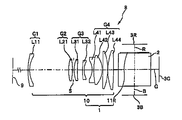
図1に、本発明の実施例を説明するための参考例1に係る投写用ズームレンズ1を用いたプロジェクタの光学系を示してある。また、図2に、本例の投写用ズームレンズ1が、拡大表示する状態である広角端(a)、標準状態である望遠端(c)および中間の状態(b)における各レンズの位置を示してある。例示したプロジェクタ8の全体的な構成は図13に基づき説明したものと同様であり、その光学系のうち、投写用ズームレンズに関する部分を図1に抜き出して示してある。本図に示したプロジェクタ装置8においては不図示の光源からの光が赤色、緑色および青色に分割され、画像形成装置であるそれぞれの液晶パネル3R、3Gおよび3Rを通りダイクロイックプリズム2によって合成され、さらに、投写用ズームレンズ1によってスクリーン9に投写される。このようにして、スクリーン9には、液晶パネル3R、3Gおよび3Rに形成された画像が合成されたカラー画像が形成される。本例の投写用ズームレンズ1は、ダイクロイックプリズム2のスクリーン9に配置された各光束R光、G光およびB光に共通の投影レンズ10と、ダイクロイックプリズム2の赤色Rの光源側に配置された補助レンズ11Rと、ダイクロイックプリズム2の青色Gの光源側に配置された補助レンズ11Bとを備えている。
[Reference Example 1]
FIG. 1 shows an optical system of a projector using a
本例の投写用ズームレンズ1の投影レンズ10は、スクリーン9の側から4つのレンズ群G1〜G4にグループ分けされた8枚のレンズL11〜L44によって構成されており、各レンズの詳細なデータは以下に示した通りである。最もスクリーン9の側に配置された第1のレンズ群G1は、負の屈折力を備えたレンズ群であり、本例では、スクリーン9の側に凸の負のメニスカスレンズL11の1枚構成となっている。この第1のレンズ群G1は変倍中に位置が動かされることはない。
The
次に配置された変倍用の第2のレンズ群G2は、正の屈折力を備えたレンズ群であり、本例では、両凸の正レンズL21の1枚構成となっている。この変倍用の第2のレンズ群G2は、広角端から望遠端に向かって入射側から反対のスクリーン9の側に向かって光軸上を移動し、所定の倍率の投写画像がスクリーン上に得られるようになっている。これに続く第3のレンズ群G3は、変倍時に光軸に沿って移動する補正用のレンズ群であり、負の屈折力を備えたレンズ群が採用されている。本例の投写用ズームレンズ1では、スクリーン側に凸の正レンズL31と、両凹の負レンズL32との組合せで構成されている。
The second lens group G2 for zooming arranged next is a lens group having a positive refractive power, and in this example, has a single biconvex positive lens L21. The second lens group G2 for zooming moves on the optical axis from the entrance side to the opposite side of the
投写用ズームレンズ1の投影レンズ10のうち、最も入射側の第4のレンズ群は、全体が正の屈折力のレンズ群であり、スクリーン側からダブレットをなす両凹の負レンズL41および両凸の正レンズL42と、入射側に凸の正レンズL43、およびスクリーン側に凸の正レンズL44で構成されている。
Of the
さらに、本例の投写用ズームレンズ1は、補助レンズ11として、R光側に弱いパワーの入射側に凸の正レンズ11Rがダイクロイックプリズム2の面にほぼ密着するように配置され、B光側に弱いパワーの入射側に凹の負レンズ11Bが同様に配置されている。そして、G光側には補助レンズが設けられていない。このように、補助レンズ11Rおよび11Bは、それぞれの波長に適した異なった曲率が付加されており、これによってその波長に適した補正を行って投影レンズ10で倍率色収差が発生するのを未然に防止するようにしている。
Further, in the
このような本例の投写用ズームレンズ1は、投影レンズ10が負−正−負−正の4つのレンズ群によって構成されており、レトロフォーカス型の組合せになるので長いバックフォーカスが確保でき、入射側がテレセントリックとなった投写用ズームレンズ1となっている。従って、上述したように、ダイクロイックプリズム、あるいは液晶パネルをライトバルブに用いたプロジェクタ8に適した投影用のズームレンズとなっている。また、本例の投写用ズームレンズ1は、負の屈折力のレンズ群G1がスクリーン側に先行して設けられているので大きな画角が得られ、広角性能の優れた小型で大きな画像を投写できるズームレンズである。
In the
さらに、本例の投写用ズームレンズ1においては、倍率色収差を補正するために弱いパワーの補助レンズ11Rおよび11Bを設けてあるので、投影レンズ10においては、第1のレンズ群G1および第2のレンズ群G2が一枚構成であり、色消し用としてパワーの異なる複数のレンズの組み合わせ、あるいは、ダブレットをなす複数レンズの組み合わせが採用されていない。また、第3のレンズ群G3も色消し用にダブレットとする構成は採用されていない。したがって、投影レンズ10は8枚構成というほぼ最小の構成で実現されており、コンパクトでありながら十分な広角性能を持ち、さらに明るくF値の小さな投写用ズームレンズ1を実現することができる。このため、本例の投写用ズームレンズ1を用い、短い投影距離で明るい大画像を投写できる小型のプロジェクタ装置8を提供することができる。
Further, in the
従来の投写用レンズにおいてはレンズ群などの単位でパワーの異なるレンズを組み合わせて色消しを行っていた。これに対し、本例においては、3板式のプロジェクタ装置などでは各色の画像が形成されることに着目し、各色の光束に倍率色収差を補正できる程度で結像性能に影響を与えない程度のパワーの補正レンズを個々に挿入することにより色消しを行い、投影レンズ側で色収差補正するための負荷を大幅に小さくしている。すなわち、この投写用ズームレンズは、入射側がテレセントリックとなったカラー画像の投写用ズームレンズであって、スクリーン側に配置された赤色、緑色および青色の光束に共通する複数枚構成のズーミング可能な投影レンズと、赤色または青色の光源側に配置された補助レンズとを有することを特徴としている。 In conventional projection lenses, achromatization is performed by combining lenses having different powers in units such as lens groups. On the other hand, in this example, attention is paid to the fact that an image of each color is formed in a three-plate type projector device or the like, and the power is sufficient to correct the chromatic aberration of magnification in the luminous flux of each color but not to affect the imaging performance. The achromatism is performed by inserting the correction lenses individually, thereby greatly reducing the load for correcting the chromatic aberration on the projection lens side. In other words, this projection zoom lens is a zoom lens for projection of a color image in which the incident side is telecentric, and has a plurality of zoomable projections common to the red, green and blue light beams arranged on the screen side. It is characterized by having a lens and an auxiliary lens arranged on the red or blue light source side.
赤色あるいは青色の光束を基準として他の色の光束を補正するように補助レンズを設けてももちろん良い。可視光の中央領域である緑色の光束を基準として、赤色、青色またはその両方の光束に倍率色収差の補正ができる程度のパワーの補助レンズを設けることにより、結像性能に影響を及ぼさずに倍率色収差の補正が可能である。そして補助レンズにより、投影レンズに対して色ずれが少なくなるように色毎にすでに補正された光束を入射することができる。したがって、投影レンズでは倍率色収差の補正を厳しく行う必要がないので、少ない構成枚数の投影レンズによって明瞭で色ずれの非常に少ない画像を投写することが可能となる。このため、コンパクトで軽く、さらに、明るい画像が得られる投写用ズームレンズを提供することができる。また、投影レンズにおいて倍率色収差の補正を行うために従来用いていた高屈折率なガラスレンズや異常分散性のガラスレンズなどの高価なレンズも不要となる。したがって、この投写用ズームレンズと、この投写用ズームレンズの入射側に赤色、緑色および青色の各々の投写用の画像を供給可能な液晶パネルなどの画像形成装置とを備えたプロジェクタ装置は、色ずれがなくクリアな画像を投写でき、パーソナルコンピュータなどの出力装置として十分な結像性能を発揮できる。そして、軽くコンパクトなプロジェクタ装置として低コストで供給することができる。 補助 Of course, an auxiliary lens may be provided so as to correct a light beam of another color based on a light beam of red or blue. By providing an auxiliary lens with enough power to correct chromatic aberration of magnification in the red, blue or both light beams with reference to the green light beam, which is the central region of visible light, the magnification is not affected by the imaging performance. Chromatic aberration can be corrected. By the auxiliary lens, a light beam that has already been corrected for each color so as to reduce color shift to the projection lens can be incident. Therefore, since it is not necessary to strictly correct the chromatic aberration of magnification in the projection lens, it is possible to project a clear image with very little color shift by using a small number of components of the projection lens. For this reason, it is possible to provide a compact and lightweight projection zoom lens capable of obtaining a bright image. Further, expensive lenses such as a high-refractive-index glass lens and an anomalous dispersion glass lens conventionally used for correcting lateral chromatic aberration in the projection lens become unnecessary. Therefore, a projector device including this projection zoom lens and an image forming apparatus such as a liquid crystal panel capable of supplying each of the projection images of red, green, and blue to the incident side of the projection zoom lens has a A clear image without any displacement can be projected, and sufficient imaging performance as an output device such as a personal computer can be exhibited. And it can be supplied at low cost as a light and compact projector device.
このような投写用ズームレンズは、3レンズ方式のプロジェクタ装置に対してもちろん適用できるが、ダイクロイックミラーあるいはダイクロイックプリズムを用いた1レンズ方式のプロジェクタ装置であれば、投影レンズは1つですむ。投写用の画像を1つに合成可能なダイクロイックプリズムを用いたプロジェクタ装置においては、投影レンズをダイクロイックプリズムのスクリーン側に配置し、補正レンズをダイクロイックプリズムの各々の光束の画像形成装置側に配置することが可能である。したがって、この投写用ズームレンズを、ダイクロイックプリズムの画像形成装置側に新たに薄い補助レンズが付加された、ほとんどプロジェクタ装置の基本的な構成には影響を与えない配置で導入することができる。 も ち ろ ん Such a projection zoom lens can of course be applied to a three-lens projector system, but a single-lens projector system using a dichroic mirror or a dichroic prism requires only one projection lens. In a projector device using a dichroic prism capable of combining projection images into one, a projection lens is arranged on the screen side of the dichroic prism, and a correction lens is arranged on the image forming apparatus side of each light beam of the dichroic prism. It is possible. Therefore, the projection zoom lens can be introduced in an arrangement in which a thin auxiliary lens is newly added to the image forming apparatus side of the dichroic prism and hardly affects the basic configuration of the projector apparatus.
この投写用ズームレンズに用いられる補助レンズは、結像性能に影響がでない程度の非常に弱いパワーであることが望ましいので、補助レンズは一枚構成で十分である。したがって、投影レンズと補助レンズという組み合わせであってもパワーの弱いレンズを一枚追加するだけで良く、従来の投写用レンズよりも簡易な構成で実現できる。 It is desirable that the auxiliary lens used in this projection zoom lens has a very weak power that does not affect the imaging performance, so that a single auxiliary lens is sufficient. Therefore, even if a combination of a projection lens and an auxiliary lens is used, it is only necessary to add a single lens having low power, and it can be realized with a simpler configuration than a conventional projection lens.
また、補助レンズは液晶パネルに近い位置に配置されるので、液晶パネルと同程度の材質、すなわち、プラスチック製のレンズを採用することも可能である。さらに、面精度も液晶パネルと同程度で問題はなく、従来の投写用ズームレンズに用いられるレンズの数十分の1、数百分の1あるいはそれ以下の面精度のレンズでも十分な性能を発揮できる。したがって、補助レンズを追設してもコストあるいは投写用ズームレンズの配置などに与える影響はなく、後述するように投影レンズの構成を簡略化できるので、それに伴う効果を最大限に引き出すことができる。 Further, since the auxiliary lens is arranged at a position close to the liquid crystal panel, it is possible to employ a lens made of the same material as the liquid crystal panel, that is, a plastic lens. Further, the surface accuracy is comparable to that of the liquid crystal panel, and there is no problem. Even a lens having a surface accuracy of one-tenth, one-hundredth or less of the lens used in the conventional projection zoom lens has sufficient performance. Can demonstrate. Therefore, even if the auxiliary lens is additionally provided, there is no effect on the cost, the arrangement of the projection zoom lens, and the like, and the configuration of the projection lens can be simplified as described later, so that the accompanying effect can be maximized. .
さらに、補正レンズで色収差の補正が行われているので、投影レンズの構成枚数を少なくすることができ、投写用レンズ全体としては従来の投写用レンズよりも少ない枚数で同等あるいはそれ以上の結像性能、特に、倍率色収差の補正能力の高い投写用ズームレンズを提供できる。 Furthermore, since the chromatic aberration is corrected by the correction lens, the number of components of the projection lens can be reduced, and as a whole the projection lens has the same or larger image formation with a smaller number than the conventional projection lens. It is possible to provide a projection zoom lens having high performance, in particular, high ability to correct lateral chromatic aberration.
また、以下の実施例で示すように、第1のレンズ群を非球面にすることによって性能を向上することができる。この投写用ズームレンズは、構成枚数が少なく明るい画像が得られる構成なので、プラスチックレンズを多用することが可能であり、コストを下げることができると共に非球面を導入して容易に結像性能を向上できる。 性能 Further, as shown in the following examples, the performance can be improved by making the first lens group aspherical. Since this projection zoom lens has a small number of components and can obtain a bright image, it is possible to use many plastic lenses, which can reduce the cost and easily improve the imaging performance by introducing an aspherical surface. it can.
さらに、本例の投写用ズームレンズ1においては、投影レンズ10の波長546.1nmのG光の焦点距離feと、投影レンズ10の波長610nmのR光または波長460nmのB光の焦点距離fcと、補助レンズ11Rまたは11Bの焦点距離fchとが次の式を満たすようにして、補助レンズ11により十分な倍率色収差補正ができると共に、投影レンズ10の結像性能には影響を与えず、良好な結像性能を持った投写用ズームレンズ1が選られるようにしている。
Further, in the
250 <|(fc−fe)×fch|< 1000 ・・・(1)
可視光の中央領域の緑色の光束(本明細書ではG光)に相当する波長546.1nmの投影レンズの焦点距離feと、他の色の光束(波長610nmは赤色の光束(R光)、波長460nmは青色の光束(B光))に相当する波長の投影レンズの焦点距離fcとの差と、補助レンズの焦点距離fcの積の絶対値が(1)式の下限を下回ると、望遠端における倍率色収差の補正が困難となり、さらに、補助レンズに結像レンズとしての効果が現れて投写用レンズの結像性能に影響が現れてしまう。一方、(1)式の上限を上回ると、補助レンズとしての性能が不足し倍率色収差の除去効果が得られず、広角端における倍率色収差の除去ができなくなってしまう。
250 <| (fc−fe) × fch | <1000 (1)
A focal length fe of the projection lens having a wavelength of 546.1 nm corresponding to a green light flux (G light in the present specification) in the central region of visible light, a light flux of another color (a red light flux (R light) at a wavelength of 610 nm), If the absolute value of the product of the difference between the focal length fc of the projection lens and the focal length fc of the auxiliary lens at a wavelength of 460 nm corresponding to the blue light flux (B light) falls below the lower limit of Expression (1), telephoto is obtained. It becomes difficult to correct the chromatic aberration of magnification at the end, and the effect of the auxiliary lens as an imaging lens appears, thereby affecting the imaging performance of the projection lens. On the other hand, when the value exceeds the upper limit of the expression (1), the performance as the auxiliary lens is insufficient, and the effect of removing the chromatic aberration of magnification cannot be obtained, and the chromatic aberration of magnification at the wide angle end cannot be removed.
また、投影レンズ10の第1のレンズ群G1の焦点距離f1と、第2群のレンズ群G2の焦点距離f2とが次の式を満たすようにして収差補正が良好な投写用ズームレンズが選られるようにしている。
Also, a focal length f1 of the first lens group G1 of the
−2.5 <(f1/f2)< −0.5 ・・・(2)
投影レンズの第1のレンズ群の焦点距離f1と、第2のレンズ群の焦点距離f2との比が(2)式の下限を下回ると、像面湾曲が発生しやすくなり投影レンズ側の結像性能が低下するので広角端から望遠端にわたる全域で倍率色収差が発生してしまう。一方、(2)式の上限を上回ると投影レンズのバックフォーカスが長く取れずにテレセントリックな光学系としての性能を得ることが難しくなり、また、歪曲収差が発生して易くなる。
−2.5 <(f1 / f2) <− 0.5 (2)
If the ratio of the focal length f1 of the first lens group of the projection lens to the focal length f2 of the second lens group falls below the lower limit of the expression (2), curvature of field is likely to occur, and the projection lens side will have a smaller curvature. Since the image performance deteriorates, chromatic aberration of magnification occurs in the entire region from the wide-angle end to the telephoto end. On the other hand, when the value exceeds the upper limit of the expression (2), the back focus of the projection lens cannot be long, and it is difficult to obtain the performance as a telecentric optical system, and distortion is likely to occur.
以下に示すレンズデータにおいて、riはスクリーン側から順番に並んだ各レンズ面の曲率半径、diはスクリーン側から順番に並んだ各レンズ面の間の距離、niはスクリーン側から順番に並んだ各レンズの屈折率(d線)、νiはスクリーン側から順番に並んだ各レンズのアッベ数(d線)を示す。また、本例の投写用ズームレンズ1は、第2のレンズ群G2の入射側に絞りSを設けてあり、絞りSと両側のレンズ面との距離も記載している。以下に示す各実施例のレンズデータについても同様である。また、データ内のINFは絞りおよびプリズムの面を示しており、長さの単位は特記しない限りmmで記載してある。
レンズデータ
i ri di ni νi
1: 103.587 10.00 1.71736 29.50 レンズL11
2: 28.697 D2
3: 65.150 4.80 1.72916 54.67 レンズL21
4: -81.448 0.20
5: INF D5 絞りS
6: 62.453 3.50 1.84666 23.78 レンズL31
7: 218.722 14.90
8: -57.895 2.00 1.78590 43.93 レンズL32
9: 54.256 D9
10: -55.451 2.40 1.84666 23.78 レンズL41
11: 56.907 10.10 1.56384 60.83 レンズL42
12: -36.757 0.20
13: 231.976 6.60 1.67003 47.20 レンズL43
14: -74.886 0.20
15: 57.964 7.10 1.67003 47.20 レンズL44
16: 18608.827
17: INF 33.00 1.51680 64.20 プリズム
18: INF
19R: INF 1.00 1.51680 64.20 補助レンズ11R
19G: INF
19B: INF 1.00 1.51680 64.20 補助レンズ11B
20R: -1600
20B: 850
ズーム状態 f D2 D5 D9 FNo.
広角端 37.38 41.36 0.80 10.31 2.50
中間 43.0 35.05 9.22 8.20 2.70
望遠端 48.7 35.05 18.31 4.11 2.90
波長546.1 nmの焦点距離(fe) 37.40
波長610 nmの補助レンズ以外の焦点距離(fc1) 37.55
波長610 nmの補助レンズの焦点距離(fch1) 3101.3
波長460 nmの補助レンズ以外の焦点距離(fc2) 37.13
波長460 nmの補助レンズの焦点距離(fch2)‐1620.8
第1のレンズ群G1の焦点距離(f1) -58.15
第2のレンズ群G2の焦点距離(f2) 50.12
(1)式は 610 nmについて(fc1−fe)×fch1=465.2
460 nmについて(fc2−fe)×fch2=437.6
(2)式は f1/f2 = -1.16
であり、上述した条件を満足する投写用ズームレンズである。
In the lens data shown below, ri is the radius of curvature of each lens surface arranged in order from the screen side, di is the distance between each lens surface arranged in order from the screen side, and ni is each arranged in order from the screen side. The refractive index of the lens (d-line) and νi indicate the Abbe number (d-line) of each lens arranged in order from the screen side. Further, in the
Lens data i ri di ni νi
1: 103.587 10.00 1.71736 29.50 Lens L11
2: 28.697 D2
3: 65.150 4.80 1.72916 54.67 Lens L21
4: -81.448 0.20
5: INF D5 Aperture S
6: 62.453 3.50 1.84666 23.78 Lens L31
7: 218.722 14.90
8: -57.895 2.00 1.78590 43.93 Lens L32
9: 54.256 D9
10: -55.451 2.40 1.84666 23.78 Lens L41
11: 56.907 10.10 1.56384 60.83 Lens L42
12: -36.757 0.20
13: 231.976 6.60 1.67003 47.20 Lens L43
14: -74.886 0.20
15: 57.964 7.10 1.67003 47.20 Lens L44
16: 18608.827
17: INF 33.00 1.51680 64.20 Prism
18: INF
19R: INF 1.00 1.51680 64.20
19G: INF
19B: INF 1.00 1.51680 64.20
20R: -1600
20B: 850
Zoom status f D2 D5 D9 FNo.
Wide-angle end 37.38 41.36 0.80 10.31 2.50
Intermediate 43.0 35.05 9.22 8.20 2.70
Telephoto end 48.7 35.05 18.31 4.11 2.90
Focal length at 546.1 nm (fe) 37.40
Focal length (fc1) other than auxiliary lens of wavelength 610 nm 37.55
Focal length of the auxiliary lens of wavelength 610 nm (fch1) 3101.3
37.13 Focal length (fc2) other than auxiliary lens with wavelength of 460 nm
Focal length (fch2) of 460 nm wavelength auxiliary lens-1620.8
Focal length (f1) of first lens group G1 -58.15
Focal length (f2) of second lens group G2 50.12
The expression (1) is (fc1-fe) × fch1 = 465.2 for 610 nm.
For 460 nm, (fc2-fe) × fch2 = 437.6
Equation (2) is f1 / f2 = -1.16
This is a projection zoom lens satisfying the above conditions.
なお、レンズ間隔D2は、レンズ先端から2.4mの位置に結像したときの数値を示してあり、以下の実施例においても同様である。 Note that the lens interval D2 is a numerical value when an image is formed at a position 2.4 m from the front end of the lens, and the same applies to the following embodiments.
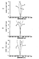
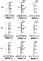
図3に本例の投写用ズームレンズの広角端(a)、中間(b)および望遠端(c)における球面収差、非点収差ならびに歪曲収差をそれぞれ示してある。球面収差図においてはR光(620.0nm)を破線、G光(546.1nm)を実線およびB光(460.0nm)を一点鎖線で各波長の収差を示し、非点収差図においてはタンジェンシャル光線(T)およびサジタル光線(S)を示してある。また、非点収差および歪曲収差は像高さを縦軸に対して示してある。さらに、図4に本例の投写用ズームレンズの広角端(a)、中間(b)および望遠端(c)における倍率色収差を示してあり、R光(破線)とB光(一点鎖線)の倍率色収差(横の色収差)をG光(実線)を基準とし、像高さを縦軸として示してある。なお、以下の各実施例においても同様である。 FIG. 3 shows the spherical aberration, astigmatism, and distortion at the wide-angle end (a), middle (b), and telephoto end (c) of the projection zoom lens of this example, respectively. In the spherical aberration diagram, the R light (620.0 nm) is indicated by a broken line, the G light (546.1 nm) is indicated by a solid line, and the B light (460.0 nm) is indicated by an alternate long and short dash line. The tangential ray (T) and the sagittal ray (S) are shown. The astigmatism and the distortion show the image height with respect to the vertical axis. FIG. 4 shows the chromatic aberration of magnification at the wide-angle end (a), the middle (b), and the telephoto end (c) of the projection zoom lens of the present example, and shows the R light (broken line) and the B light (dashed line). The chromatic aberration of magnification (lateral chromatic aberration) is shown on the basis of G light (solid line), and the image height is shown on the vertical axis. The same applies to the following embodiments.
本例の投写用ズームレンズは、焦点距離の範囲が37.4〜48.7と短く、さらに、F値が2.5〜2.9と明るいレンズである。さらに、広角端、中間および望遠端の各状態における倍率色収差も極めて小さい範囲に収まっている。また、各状態における球面収差、非点収差および歪曲収差も十分に小さく実用上問題のない値であり、良好な結像性能を本例の投写用ズームレンズは備えている。このように、本例の投写用ズームレンズ1は、補正レンズ11Rおよび11BをR光およびB光を各々補正できるようにダイクロイックプリズム2の上流に設置することにより、投影レンズ10で無理な色消しを行う必要がなくなる。したがって、8枚構成と低コストなタイプの投写用ズームレンズでありながら倍率色収差が小さく結像性能の良い投写用ズームレンズが得られており、画素の色ずれの少ない高解像度の画像をスクリーンに形成可能な投写用ズームレンズである。また、少ないレンズ枚数で色収差を補正できるので、小型軽量で、明るく、広角性能が向上するなどの上述したようなレンズ枚数を削減することによって得られるさまざまなメリットを備えた投写用ズームレンズを提供することができる。
ズ ー ム The projection zoom lens of this example is a lens having a short focal length range of 37.4 to 48.7 and an F value of 2.5 to 2.9. Further, the chromatic aberration of magnification in each of the wide-angle end state, the intermediate state, and the telephoto end state is within a very small range. In addition, the spherical aberration, astigmatism, and distortion in each state are sufficiently small and have no practical problems, and the projection zoom lens of this embodiment has good imaging performance. As described above, in the
[参考例2]
図5に、本発明を説明するための参考例2に係る投写用ズームレンズ1を用いたプロジェクタ装置8の光学系を抜き出して示してある。また、図6に、広角端(a)、標準状態である望遠端(c)および中間の状態(b)における各レンズの位置を示してある。なお、以下においては、上記と共通する部分については同じ符号を付して説明を省略する。本例の投写用ズームレンズ1もダイクロイックプリズム2のスクリーン9の側に配置された投影レンズ10と、ダイクロイックプリズム2の光源側に配置された補助レンズ11を備えており、本例においては、R光用の補助レンズ11Rのみを設置してある。また、投影レンズ10は、上記と同様に4つのレンズ群G1〜G4にグループ分けされた8枚のレンズL11〜L44によって構成されており、第4のレンズ群G4を前群G41(第4群)と後群G42(第5群)に分け、ズーミング時に独立して光軸上を移動できるようにしている。このため、広角端から望遠端にわたり中間領域も含めて画像を表示する際に各々のレンズ群の適当な部分を用いて結像できるので、いっそう収差および像面湾曲を改善することが可能となる。特に、本例の投写用ズームレンズ1ではB光の倍率色収差を抑えて性能アップを図ることができるので、B光用の補正レンズを省いても十分な倍率色収差補正が可能であり、補正レンズ11としてはR光用の1枚を配置してある。
[Reference Example 2]
FIG. 5 shows an extracted optical system of a
各レンズの詳細なデータは以下に示した通りである。
レンズデータ
i ri di ni νi
1: 80.338 2.00 1.67003 47.20 レンズL11
2: 32.260 D2
3: 53.072 4.80 1.58913 61.25 レンズL21
4: -85.750 1.20
5: INF D5 絞りS
6: 33.484 4.20 1.80518 25.46 レンズL31
7: 103.223 6.70
8: 95.702 2.00 1.76182 26.61 レンズL32
9: 22.895 D9
10: -19.747 2.00 1.84666 23.78 レンズL41
11: 75.960 10.70 1.62041 60.34 レンズL42
12: -25.966 D12
13: -2531.677 6.30 1.74950 35.04 レンズL43
14: -60.454 0.20
15: 66.821 7.00 1.67003 47.20 レンズL44
16: -356.185
17: INF 33.00 1.51680 64.20 プリズム
18: INF
19R: INF 1.00 1.51680 64.20 補助レンズ11R
19G: INF
19B: INF
20R: -5700
ズーム状態 f D2 D5 D9 D12 FNo.
広角端 37.36 49.20 0.80 10.20 0.80 2.50
中間 43.0 39.50 7.75 9.83 3.92 2.66
望遠端 48.7 31.76 17.87 6.85 4.53 2.82
波長546.1 nmの焦点距離(fe) 37.31
波長610 nmの補助レンズ以外の焦点距離(fc1) 37.36
波長610 nmの補助レンズの焦点距離(fch1) 11048.5
第1のレンズ群G1の焦点距離(f1) -81.41
第2のレンズ群G2の焦点距離(f2) 56.15
(1)式は 610 nmについて(fc1−fe)×fch1=552.4
(2)式は f1/f2 = -1.50
であり、上述した条件を満足するレンズである。
Detailed data of each lens is as shown below.
Lens data i ri di ni νi
1: 80.338 2.00 1.67003 47.20 Lens L11
2: 32.260 D2
3: 53.072 4.80 1.58913 61.25 Lens L21
4: -85.750 1.20
5: INF D5 Aperture S
6: 33.484 4.20 1.80518 25.46 Lens L31
7: 103.223 6.70
8: 95.702 2.00 1.76182 26.61 Lens L32
9: 22.895 D9
10: -19.747 2.00 1.84666 23.78 Lens L41
11: 75.960 10.70 1.62041 60.34 Lens L42
12: -25.966 D12
13: -2531.677 6.30 1.74950 35.04 Lens L43
14: -60.454 0.20
15: 66.821 7.00 1.67003 47.20 Lens L44
16: -356.185
17: INF 33.00 1.51680 64.20 Prism
18: INF
19R: INF 1.00 1.51680 64.20
19G: INF
19B: INF
20R: -5700
Zoom status f D2 D5 D9 D12 FNo.
Wide-angle end 37.36 49.20 0.80 10.20 0.80 2.50
Intermediate 43.0 39.50 7.75 9.83 3.92 2.66
Telephoto end 48.7 31.76 17.87 6.85 4.53 2.82
Focal length at 546.1 nm (fe) 37.31
Focal length (fc1) other than auxiliary lens of wavelength 610 nm 37.36
Focal length of auxiliary lens with wavelength of 610 nm (fch1) 11048.5
Focal length (f1) of first lens group G1 -81.41
Focal length (f2) of second lens group G2 56.15
Equation (1) is (fc1-fe) × fch1 = 552.4 for 610 nm.
Equation (2) is f1 / f2 = -1.50
Which satisfies the above conditions.
図7に本例の投写用ズームレンズの広角端(a)、中間(b)および望遠端(c)における球面収差、非点収差ならびに歪曲収差をそれぞれ示し、また、図8にそれぞれの状態の倍率色収差を示してある。本例の投写用ズームレンズも投影レンズ10が8枚構成の簡易で低コストな構成でありながら、倍率色収差は非常に狭い範囲に収められて倍率色収差除去が極めて良好に行われている投写用ズームレンズであることがわかる。また、図7に示した各収差の値は広角端、中間および望遠端のそれぞれにおいて実施例1よりもさらに良好な値となっており、結像性能の優れた投写用ズームレンズとなっていることがわかる。
FIG. 7 shows the spherical aberration, astigmatism, and distortion at the wide-angle end (a), the middle (b), and the telephoto end (c) of the projection zoom lens of this example, respectively. FIG. 8 shows the respective states. The chromatic aberration of magnification is shown. The projection zoom lens of this example is also a simple and low-cost configuration having eight
さらに焦点距離の範囲が37.36〜48.7と短く、F値が2.5〜2.82と明るいレンズであるので、小型軽量で、色ずれがなく、コンピュータの出力用として適した明るい高解像の画像を投写できる投写用ズームレンズを提供できる。 Furthermore, since the lens has a short focal length range of 37.36 to 48.7 and a bright F value of 2.5 to 2.82, it is small and lightweight, has no color shift, and is suitable for computer output. A projection zoom lens capable of projecting a high-resolution image can be provided.
[実施例1]
図9に、本発明の実施例に係る投写用ズームレンズ1を用いたプロジェクタ装置8の光学系を抜き出して示してある。また、図10に、広角端(a)、標準状態である望遠端(c)および中間の状態(b)における各レンズの位置を示してある。本例の投写用ズームレンズ1も投影レンズ10に加え、ダイクロイックプリズム2の光源側に配置された補助レンズ11を備えており、R光用の補助レンズ11Rのみを設置してある。また、投影レンズ10は、上記と同様に、4つのレンズ群G1〜G4にグループ分けされた8枚のレンズL11〜L44によって構成されている。すなわち、最もスクリーン9の側に配置された第1のレンズ群G1は、負の屈折力を備えたレンズ群であり、本例では、スクリーン9の側に凸の負のメニスカスレンズL11の1枚構成となっている。次に配置された第2のレンズ群G2は、正の屈折力を備えたレンズ群であり、本例では、両凸の正レンズL21の1枚構成となっている。これに続く第3のレンズ群G3は、負の屈折力を備えたレンズ群が採用されている。本例の投影レンズ10では、スクリーン側に凸の正レンズL31と、負レンズL32との組合せで構成されている。投影レンズ10のうち、最も入射側の第4のレンズ群は、全体が正の屈折力のレンズ群であり、スクリーン側からダブレットをなす両凹の負レンズL41および両凸の正レンズL42と、入射側に凸の正レンズL43、およびスクリーン側に凸の正レンズL44で構成されている。第4のレンズ群G4は上述の投写用ズームレンズと同様に前群G41(第4群)と後群G42(第5群)に分けたタイプとなっている。さらに、本例の投写用ズームレンズは、第1のレンズ群G1のレンズL11と、第2のレンズ群G2のレンズL21としてプラスチック製のレンズを採用し、さらに、第1のレンズ群G1のレンズL11のスクリーン側の面(R1)を非球面化している。
[Example 1]
FIG. 9 shows an extracted optical system of a
このように、本例および上記参考例に係る投写用ズームレンズは、補助レンズ11の採用により、投影レンズ10の構成枚数を削減でき、さらに、各群を色消し用に2枚構成にしたり、ダブレットタイプのレンズを採用する必要がない。また、レンズの材質の選定も自由であり、本例のように第1および第2のレンズ群のような口径の大きなレンズに対しプラスチック製のレンズを採用していっそうのコストダウンを図ることができる。また、プラスチック製のレンズを採用することにより、レンズ面を非球面化することも容易であり、コストダウンを図ると共に投写用ズームレンズの結像性能をアップすることができる。
As described above, the projection zoom lenses according to the present example and the reference example can reduce the number of components of the
各レンズの詳細なデータは以下に示した通りである。
レンズデータ
i ri di ni νi
1: 72.770 2.00 1.49140 57.82 レンズL11
2: 26.840 D2
3: 45.998 10.00 1.49140 57.82 レンズL21
4: -78.539 0.20
5: INF D5 絞りS
6: 31.882 5.10 1.84666 23.78 レンズL31
7: 161.000 1.20
8: 134.695 6.00 1.76182 26.61 レンズL32
9: 21.745 D9
10: -18.813 2.00 1.84666 23.78 レンズL41
11: 96.720 9.60 1.62041 60.34 レンズL42
12: -24.788 D12
13: -926.987 6.30 1.74950 35.04 レンズL43
14: -67.514 0.20
15: 57.817 7.80 1.67003 47.20 レンズL44
16: -310.538
17: INF 33.00 1.51680 64.20 プリズム
18: INF
19R: INF 1.00 1.51680 64.20 補助レンズ11R
19G: INF
19B: INF
20R: -5700
ズーム状態 f D2 D5 D9 D12 FNo.
広角端 37.40 52.81 0.80 13.82 0.80 2.50
中間 43.0 42.43 10.57 11.54 3.70 2.66
望遠端 48.7 34.21 23.07 7.62 3.34 2.83
面1(レンズL11)の非球面係数
K=0.00000
A= 0.972391×10⁻⁶ ,B=0.190336×10⁻⁸
C=−0.367785×10⁻¹¹ ,D=0.340506×10⁻¹⁴
ただし、非球面式は次の通りである。
x = (y2 /r)/[1+{1−(1+K)(y2 /r2 )}1/2 ]
+ Ay4 +By6 +Cy8 +Dy10 ・・・(3)
波長546.1 nmの焦点距離(fe) 37.405
波長610 nmの補助レンズ以外の焦点距離(fc1) 37.446
波長610 nmの補助レンズの焦点距離(fch1) 11400
第1のレンズ群G1の焦点距離(f1) -87.46
第2のレンズ群G2の焦点距離(f2) 60.41
(1)式は 610 nmについて(fc1−fe)×fch1=467.4
(2)式は f1/f2 = -1.45
であり、上述した条件を満足するレンズである。
Detailed data of each lens is as shown below.
Lens data i ri di ni νi
1: 72.770 2.00 1.49140 57.82 Lens L11
2: 26.840 D2
3: 45.998 10.00 1.49140 57.82 Lens L21
4: -78.539 0.20
5: INF D5 Aperture S
6: 31.882 5.10 1.84666 23.78 Lens L31
7: 161.000 1.20
8: 134.695 6.00 1.76182 26.61 Lens L32
9: 21.745 D9
10: -18.813 2.00 1.84666 23.78 Lens L41
11: 96.720 9.60 1.62041 60.34 Lens L42
12: -24.788 D12
13: -926.987 6.30 1.74950 35.04 Lens L43
14: -67.514 0.20
15: 57.817 7.80 1.67003 47.20 Lens L44
16: -310.538
17: INF 33.00 1.51680 64.20 Prism
18: INF
19R: INF 1.00 1.51680 64.20
19G: INF
19B: INF
20R: -5700
Zoom status f D2 D5 D9 D12 FNo.
Wide-angle end 37.40 52.81 0.80 13.82 0.80 2.50
Intermediate 43.0 42.43 10.57 11.54 3.70 2.66
Telephoto end 48.7 34.21 23.07 7.62 3.34 2.83
Aspheric coefficient K of surface 1 (lens L11) = 0.000000
A = 0.972391 × 10 −6 , B = 0.190336 × 10 −8
C = −0.367785 × 10 −11 , D = 0.340506 × 10 −14
However, the aspherical expression is as follows.
x = (y 2 / r) / [1+ {1- (1 + K) (
+ Ay 4 + By 6 + Cy 8 + Dy 10 (3)
Focal length at 546.1 nm wavelength (fe) 37.405
Focal length (fc1) other than auxiliary lens of wavelength 610 nm 37.446
Focal length of an auxiliary lens with a wavelength of 610 nm (fch1) 11400
Focal length (f1) of first lens group G1 -87.46
Focal length (f2) of second lens group G2 60.41
Equation (1) is (fc1-fe) × fch1 = 467.4 for 610 nm.
Equation (2) is f1 / f2 = -1.45
Which satisfies the above conditions.
図11に本例の投写用ズームレンズの広角端(a)、中間(b)および望遠端(c)における球面収差、非点収差ならびに歪曲収差をそれぞれ示し、また、図12にそれぞれの状態の倍率色収差を示してある。本例の投写用ズームレンズも投影レンズ10が8枚構成の簡易で、さらにプラスチック製のレンズを多用したローコストな構成でありながら、倍率色収差は非常に狭い範囲に収められて色ずれの極めて少ない投写用ズームレンズである。また、図11に示した各収差の値は広角端、中間および望遠端のそれぞれにおいて実用上十分に良好な値となっており、結像性能の優れた投写用ズームレンズとなっていることがわかる。
FIG. 11 shows spherical aberration, astigmatism, and distortion at the wide-angle end (a), the middle (b), and the telephoto end (c) of the projection zoom lens of this example, respectively. FIG. 12 shows the respective states. The chromatic aberration of magnification is shown. The projection zoom lens of this example is also a simple and low-cost configuration using eight
さらに、本例の投写用ズームレンズも焦点距離の範囲が37.40〜48.7と短く、F値が2.5〜2.83と明るいレンズである。 Furthermore, the projection zoom lens of this example is also a lens having a short focal length range of 37.40 to 48.7 and a bright F value of 2.5 to 2.83.
以上に説明した投写用ズームレンズは、スクリーン側に設置される各色の光束に共通した構成の投影レンズと、各色の光束の光源側に個々に設置される補助レンズとを備えており、補助レンズの側で倍率色収差が発生しないように各波長の光束に適した補正を行った後に投影レンズに入射できるようにしている。したがって、投影レンズでは色収差補正の負担がなく、極めてシンプルで簡易な構成により高い結像性能を実現できる。このため、説明した投写用ズームレンズを用いることにより、構成枚数が少なく簡易な構成でありながら、高解像度に対応した倍率色収差の除去が可能であるという、従来の投写レンズでは相反する特性を両立させた投写用ズームレンズを提供することが可能となる。したがって、これらの投写用ズームレンズを用いることにより、今後、パーソナルコンピュータの出力装置などとして液晶等の画像形成装置のライトバルブが高解像度化するのに十分に対応でき、さらに、小型軽量で、低コストで供給可能なプロジェクタ装置を提供することができる。 The projection zoom lens described above includes a projection lens having a configuration common to the light flux of each color installed on the screen side, and an auxiliary lens individually installed on the light source side of the light beam of each color. In order to prevent the occurrence of chromatic aberration of magnification on the side, the light beam of each wavelength is corrected so as to be incident on the projection lens. Therefore, the projection lens has no burden of chromatic aberration correction, and can achieve high imaging performance with an extremely simple and simple configuration. For this reason, by using the above-described projection zoom lens, it is possible to remove chromatic aberration of magnification corresponding to high resolution while having a simple configuration with a small number of components. Thus, it is possible to provide a projected zoom lens. Therefore, by using these projection zoom lenses, the light valve of an image forming apparatus such as a liquid crystal as an output device of a personal computer can sufficiently cope with a higher resolution in the future, and furthermore, it is small, light, and low in size. A projector device that can be supplied at a low cost can be provided.
1 投写用ズームレンズ
2 ダイクロイックプリズム
3 液晶パネル
4 反射ミラー
5 ダイクロイックミラー
6 光源
7 画像形成装置
8 プロジェクタ装置
9 スクリーン
10 投影レンズ
11 補助レンズ
REFERENCE SIGNS
Claims (6)
最もスクリーン側の第1のレンズ群が非球面レンズを備えている投影レンズ。 A projection lens having a plurality of lens groups,
A projection lens wherein the first lens group closest to the screen includes an aspheric lens.
5. A projector device comprising: the projection lens according to claim 1; and an image forming apparatus capable of supplying a projection image to an incident side of the projection lens.
Priority Applications (1)
| Application Number | Priority Date | Filing Date | Title |
|---|---|---|---|
| JP2003289591A JP2004004964A (en) | 2003-08-08 | 2003-08-08 | Projection lens and projector device |
Applications Claiming Priority (1)
| Application Number | Priority Date | Filing Date | Title |
|---|---|---|---|
| JP2003289591A JP2004004964A (en) | 2003-08-08 | 2003-08-08 | Projection lens and projector device |
Related Parent Applications (1)
| Application Number | Title | Priority Date | Filing Date |
|---|---|---|---|
| JP10035836A Division JPH11231218A (en) | 1998-02-18 | 1998-02-18 | Zoom lens for projection and projector device |
Publications (2)
| Publication Number | Publication Date |
|---|---|
| JP2004004964A true JP2004004964A (en) | 2004-01-08 |
| JP2004004964A5 JP2004004964A5 (en) | 2005-05-26 |
Family
ID=30438824
Family Applications (1)
| Application Number | Title | Priority Date | Filing Date |
|---|---|---|---|
| JP2003289591A Pending JP2004004964A (en) | 2003-08-08 | 2003-08-08 | Projection lens and projector device |
Country Status (1)
| Country | Link |
|---|---|
| JP (1) | JP2004004964A (en) |
Cited By (6)
| Publication number | Priority date | Publication date | Assignee | Title |
|---|---|---|---|---|
| JP2006078704A (en) * | 2004-09-08 | 2006-03-23 | Canon Inc | Zoom optical system |
| JP2006084971A (en) * | 2004-09-17 | 2006-03-30 | Canon Inc | Zoom lens and image projector having same |
| JP2009069539A (en) * | 2007-09-13 | 2009-04-02 | Fujinon Corp | Projection type zoom lens and projection-type display device |
| US8139166B2 (en) | 2007-08-30 | 2012-03-20 | Mitsubishi Electric Corporation | Image projection apparatus and projection optical system |
| JP2015197421A (en) * | 2014-04-03 | 2015-11-09 | キヤノン株式会社 | Projection device and imaging apparatus to be used in three-dimensional shape measurement system |
| CN105527698A (en) * | 2016-01-26 | 2016-04-27 | 深圳市谛源光科有限公司 | Projection lens of DLP minisize projector |
-
2003
- 2003-08-08 JP JP2003289591A patent/JP2004004964A/en active Pending
Cited By (9)
| Publication number | Priority date | Publication date | Assignee | Title |
|---|---|---|---|---|
| JP2006078704A (en) * | 2004-09-08 | 2006-03-23 | Canon Inc | Zoom optical system |
| JP4594008B2 (en) * | 2004-09-08 | 2010-12-08 | キヤノン株式会社 | Zoom optical system |
| JP2006084971A (en) * | 2004-09-17 | 2006-03-30 | Canon Inc | Zoom lens and image projector having same |
| US7079324B2 (en) | 2004-09-17 | 2006-07-18 | Canon Kabushiki Kaisha | Zoom lens and image projection apparatus including the same |
| JP4612824B2 (en) * | 2004-09-17 | 2011-01-12 | キヤノン株式会社 | Image projection device |
| US8139166B2 (en) | 2007-08-30 | 2012-03-20 | Mitsubishi Electric Corporation | Image projection apparatus and projection optical system |
| JP2009069539A (en) * | 2007-09-13 | 2009-04-02 | Fujinon Corp | Projection type zoom lens and projection-type display device |
| JP2015197421A (en) * | 2014-04-03 | 2015-11-09 | キヤノン株式会社 | Projection device and imaging apparatus to be used in three-dimensional shape measurement system |
| CN105527698A (en) * | 2016-01-26 | 2016-04-27 | 深圳市谛源光科有限公司 | Projection lens of DLP minisize projector |
Similar Documents
| Publication | Publication Date | Title |
|---|---|---|
| JP4446521B2 (en) | Projection zoom lens and projector apparatus | |
| JP5766889B2 (en) | Projection zoom lens and projection display device | |
| JP4138324B2 (en) | Zoom lens and video camera using the same | |
| JP5132343B2 (en) | Zoom lens and image projection apparatus having the same | |
| JP4616966B2 (en) | Projection zoom lens and projector apparatus | |
| US6075653A (en) | Projecting zoom lens system and projector apparatus | |
| JP2003015036A (en) | Zoom lens for projection and projector equipped therewith | |
| US9995917B2 (en) | Projection zoom lens and projection type display device | |
| WO2013157237A1 (en) | Projection lens and projection-type display device | |
| WO2014076924A1 (en) | Zoom lens for projection and projection-type display device | |
| JP2016050989A (en) | Projection zoom lens and projection display device | |
| JP4750319B2 (en) | Projection zoom lens | |
| JP4188595B2 (en) | Projection zoom lens | |
| JP2003015037A (en) | Zoom lens for projection | |
| JP2001108900A (en) | Zoom lens for projection | |
| JPH11231218A (en) | Zoom lens for projection and projector device | |
| JP2003337283A (en) | Zoom lens for projection and enlarging projector | |
| JPH1020192A (en) | Zoom lens for projector | |
| JP3487457B2 (en) | Projection zoom lens | |
| JP2004004964A (en) | Projection lens and projector device | |
| US9383560B2 (en) | Zoom lens for projection and projection-type display apparatus | |
| JP2003295054A (en) | Zoom lens and projection display device using the same | |
| JP2000298234A (en) | Projection lens, video magnification projection system using the lens, video projector, rear projector, and multivision system using same | |
| JP5611901B2 (en) | Variable magnification optical system for projection and projection display device | |
| JPH04335610A (en) | Projection lens |
Legal Events
| Date | Code | Title | Description |
|---|---|---|---|
| A521 | Written amendment |
Free format text: JAPANESE INTERMEDIATE CODE: A523 Effective date: 20040513 |
|
| A621 | Written request for application examination |
Free format text: JAPANESE INTERMEDIATE CODE: A621 Effective date: 20040513 |
|
| A871 | Explanation of circumstances concerning accelerated examination |
Free format text: JAPANESE INTERMEDIATE CODE: A871 Effective date: 20040513 |
|
| A975 | Report on accelerated examination |
Free format text: JAPANESE INTERMEDIATE CODE: A971005 Effective date: 20040602 |
|
| A131 | Notification of reasons for refusal |
Free format text: JAPANESE INTERMEDIATE CODE: A131 Effective date: 20040615 |
|
| A521 | Written amendment |
Free format text: JAPANESE INTERMEDIATE CODE: A523 Effective date: 20040812 |
|
| A02 | Decision of refusal |
Free format text: JAPANESE INTERMEDIATE CODE: A02 Effective date: 20040924 |