JP2004004223A - Photographing device, photograph vending machine, and print media - Google Patents
Photographing device, photograph vending machine, and print media Download PDFInfo
- Publication number
- JP2004004223A JP2004004223A JP2002158696A JP2002158696A JP2004004223A JP 2004004223 A JP2004004223 A JP 2004004223A JP 2002158696 A JP2002158696 A JP 2002158696A JP 2002158696 A JP2002158696 A JP 2002158696A JP 2004004223 A JP2004004223 A JP 2004004223A
- Authority
- JP
- Japan
- Prior art keywords
- background
- photographing
- subject
- image
- unit
- Prior art date
- Legal status (The legal status is an assumption and is not a legal conclusion. Google has not performed a legal analysis and makes no representation as to the accuracy of the status listed.)
- Pending
Links
Images


Landscapes
- Cameras Adapted For Combination With Other Photographic Or Optical Apparatuses (AREA)
Abstract
Description
【0001】
【発明の属する技術分野】
この発明は写真撮影装置、写真自動販売機および印刷媒体に関し、特に、ユーザの所望する背景を用いた写真を提供することのできる写真撮影装置、写真自動販売機および印刷媒体に関する。
【0002】
【従来の技術】
コイン等の対価を投入することで、自動的に使用者の写真を撮影しプリントする写真自動販売機や、さらに撮影された使用者の画像と予め記憶されている画像であって使用者から選択された画像とを組合せた写真をプリントする写真自動販売機などが広く知られている。
【0003】
【発明が解決しようとする課題】
このような従来の写真自動販売機では、撮影用の背景として、背景を印刷した複数枚のカーテンを用いることができる。また、被写体の背後に照明装置を設けてその照明光の色を変えることができる。
【0004】
このようにして、使用者に、オリジナリティーの高い背景を提供する写真自動販売機はあるものの、より多くの種類の背景を使用者に提供することができないという問題があった。
【0005】
また、上述のようなカーテンにはしわやよじれが発生しやすく、カーテンを用いた背景では美しい写真が提供できない場合もあるという問題がある。また、平面に印刷された画像を背景とするのでは、立体感がなく、満足する写真を使用者に提供できない場合もあるという問題があった。
【0006】
また、よりリアリティある写真を提供するために、画像合成の技術としてクロマキー技術や、顔や人体の認識技術等を用いた技術が採用されているが、そのような技術をもってしても、被写体の髪の1本1本の間というような細部にわたる合成まで行なうことは不可能であり、リアリティに欠くという問題があった。特に、ソバージュやパーマ等の髪のすきまの多い髪型である使用者の場合、実際に撮影すると髪の隙間から背景が透けて見える。また、透明な衣服越しに写る背景は半透明に見える効果がある。このような効果は、上述の画像合成技術で実現することは非常に困難であり、真のリアリティある美しい写真の提供が難しいといった問題がある。
【0007】
本発明はこのような問題に鑑みてなされたものであり、オリジナリティーの高い背景であって、美しい写真を提供することのできる写真撮影装置、写真自動販売機および印刷媒体を提供することを目的とする。
【0008】
【課題を解決するための手段】
上記目的を達成するために、本発明のある局面に従うと、写真撮影装置は、被写体と背景とを撮影する撮影手段を備える写真撮影装置であって、前記背景は、透明板と透明棚とからなるスペースに配備された背景用被写体であって、前記撮影手段は、前記透明板を介して前記被写体と前記背景用被写体とを撮影する。
【0009】
また、上述の透明棚は複数の透明な棚からなり、背景用被写体は複数の透明な棚の各々に配備される複数の背景用被写体であって、撮影手段はユーザの指示に応じて複数の背景用被写体のうちから選択して背景用被写体として撮影することが望ましい。
【0010】
また、写真撮影装置は、背景用被写体を照明する照明手段をさらに備え、照明手段は、ユーザの指示に応じて選択された背景用被写体を照明することが望ましい。
【0011】
また、上述の透明板は、撮影手段によって透明板に反射した光が撮影されないような機能を備えることが望ましい。
【0012】
さらに、上述の透明板に反射した光が撮影されないような機能は、透明板に反射した光が撮影手段に到達しないような透明板の形状であることが望ましい。
【0013】
本発明の他の局面に従うと、写真撮影装置は、被写体と背景とを撮影する撮影手段を備える写真撮影装置であって、背景は表示手段である。
【0014】
また、上述の表示手段は、ユーザの指示に応じて、予め記憶されている画像を表示することが望ましい。
【0015】
また、上述の表示手段は、複数の発光素子と、ネオンランプと、映像スクリーンとのいずれかを用いて画像を表示することが望ましい。
【0016】
また、写真撮影装置は、撮影手段によって、背景が撮影されないように背景を遮断する遮断手段をさらに備えることが望ましい。
【0017】
また、写真撮影装置は、撮影手段と背景との間に第2被写体をさらに備え、撮影手段は、被写体と背景と第2被写体とを撮影することが望ましい。
【0018】
さらに、上述の第2被写体は、立体映像であることが望ましい。
本発明のさらに他の局面に従うと、写真自動販売機は、上述の写真撮影装置と、写真撮影装置で撮影された写真を印刷する印刷手段とを備える。
【0019】
また、本発明のさらに他の局面に従うと、印刷媒体は、上述の写真自動販売機における印刷手段で用いられる印刷媒体である。
【0020】
【発明の実施の形態】
以下に、図面を参照しつつ、本発明の実施の形態について説明する。以下の説明では、同一の部品および構成要素には同一の符号を付してある。それらの名称および機能も同じである。したがってそれらについての詳細な説明は繰返さない。
【0021】
[第1の実施の形態]
まず、第1の実施の形態における写真自動販売機について説明を行なう。
【0022】
図1は、本実施の形態における写真自動販売機の外観の具体例を示す図である。
【0023】
図1を参照して、本実施の形態における写真自動販売機は、筐体3の内部に写真撮影装置1が備えられ、被写体90であるユーザ9と相対する。説明の便宜上、筐体3において、ユーザ9と対向する側を前面とする。すなわち、図1の筐体3に関して紙面の左側が筐体3の前側、右側を筐体3の後側とする。なお、被写体90としては、任意の物体を選択することができるが、本実施の形態においては、ユーザ9であるものとする。
【0024】
被写体90の背後には、撮影時の背景である背景2が配備される。なお、背景2については、後に具体例を挙げ、詳細な説明を行なう。
【0025】
筐体3後部の内壁の色、あるいは模様は、撮影が効果的に行なわれるものであれば、限定されるものではない。具体的には、クロマキー合成を行なう場合は青色が施されている。その他、間接照明の効果を引出すために白色が施されていてもよいし、被写体90への色の影響(色被り)を考慮し、ピンク色、赤色および黄色等が施されていてもよい。
【0026】
図2は、図1に示される写真撮影装置1の外観の具体例を示す図である。
図2を参照して、写真撮影装置1の正面には、上部カメラ10aおよび下部カメラ10bが備えられ、ユーザ9からコイン投入口50に対価(コイン)を投入されることで、被写体90を正面および上方向から撮影する。
【0027】
写真撮影装置1の正面に備えられるスピーカ70は、BGMや各種指示等の音声情報を出力する。
【0028】
撮影された被写体90の画像は、上部ディスプレイ30aおよび下部ディスプレイ30bに表示される。また、ユーザ9は、正面に備えられる上部ディスプレイ30aに表示される撮影画像を見ながら、好みのポーズを取ることができる。
【0029】
さらに写真撮影装置1の正面に、ユーザ9からの各種指示等の入力を受付ける操作部40を備える。操作部40は、下部ディスプレイ30bと入力装置41とから構成される。下部ディスプレイ30bは、タッチパネル式の入力手段を備える。ユーザ9は、ペン形状の入力装置41で下部ディスプレイ30bに表示されるボタンにタッチし、各種指示等の入力や、印字画像の決定を行なうことができる。また、下部ディスプレイ30bに直に文字の書込みや、任意の図形の描込みを行なうことができる。また、図2に示される如く、ペン形状の入力装置41を複数備えることもできる。その場合、複数のユーザ9によって、上述の指示の入力や、図形の描込み等を行なうことができる。また、入力装置41は、コントローラ式の入力装置であってもよいし、その他の形態の入力装置であってもよい。
【0030】
ユーザ9の指示によって、撮影画像は、紙やプラスチック等のカード類、金属の装身具等の印刷媒体に印刷され、取出口60より排出されることでユーザ9に提供される。
【0031】
なお、写真撮影装置1は、上述の形態に限定されず、その他の様々な機能が備えられていてもよい。
【0032】
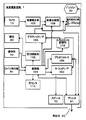
さらに図3は、図2に示される写真撮影装置1の構成を示す機能ブロック図である。
【0033】
図3を参照して、写真撮影装置1は、写真撮影装置1全体の制御を行なう制御部101を備える。制御部101は、操作部40より、操作信号を受信する。また、コイン投入口50の内部に備えられるコイン検出部51より、コイン検出信号を受信する。
【0034】
記憶部102は、複数の画像データおよびサウンドデータを記憶する。記憶部102に記憶されている画像データには、デモンストレーション画像(以下、デモ画像という)、および印刷媒体の表面に印刷されるべき複数の装飾画像などが含まれる。また、記憶部102は、制御部101において実行されるプログラムを記憶する。さらに、記憶部102は、制御部101でプログラムが実行される際の、一時的な記憶領域ともなる。
【0035】
グラフィックI/F(インタフェース)回路103は、記憶部102から記憶されている画像データを読出し、所定の記憶画像信号に変換して、画像合成部106および表示選択回路107に送信する。
【0036】
サウンドI/F回路104は、記憶部102から記憶されているサウンドデータを読出し、所定のサウンド信号に変換して、スピーカ70に送信する。
【0037】
上部カメラ10aおよび下部カメラ10bからなるカメラ10より送られる被写体90の画像信号は、画像補正部105で受信され、画像補正部105は、被写体90の画像を補正する。画像補正部105では、画像の歪補正、色調補正、画像の変形、回転、および反転等の、必要な処理を行なう。画像補正部105で補正された被写体90の画像信号は、画像合成部106に送信される。
【0038】
画像合成部106は、被写体90の画像信号を第1画像信号として受信し、グラフィックI/F回路103から送信される記憶画像の画像信号を第2画像信号として受信する。そして第1画像と第2画像とを合成する。画像合成部106での画像の合成手法は、実用新案登録第3043855号および実用新案登録第3051776号などに詳述されているため、ここではその詳細な説明を省略する。なお、画像合成部106は複数の合成手法を備え、制御部101からの制御信号により最適な合成手法を選択することが望ましい。合成された画像は、表示選択回路107およびプリンタ61に送信される。
【0039】
表示選択回路107は、画像合成部106からの合成画像信号と、グラフィックI/F回路103からの記憶画像信号とを受信し、制御部101からの制御信号に基づいて、一方の画像信号を選択して、上部ディスプレイ30aおよび下部ディスプレイ30bからなるディスプレイ30に送信する。ディスプレイ30は、表示選択回路107からの画像信号を受信して画像を表示する。
【0040】
プリンタコントローラ109は、制御部101からの制御信号に基づいて、プリンタ61を制御する。プリンタ61は、プリンタコントローラ109の制御により、画像合成部106からの合成画像信号を受信し、合成画像データに基づいて印刷画像データを生成して、当該印刷画像を所定の印刷媒体に印刷する。なお、プリンタ61は、写真撮影装置1本体に含まれていなくてもよい。その場合、プリンタコントローラ109は、LAN(Local Area Network)や専用回線等を用いて通信を行なうことで、あるいは無線による通信を行なうことで、遠隔にあるプリンタ61を制御し、当該印刷画像を印刷媒体に印刷することができる。
【0041】
照明制御部108は、カメラ10による撮影手段と同期して上部照明20aおよび下部照明20bからなる照明20が照明するよう、照明20の同期制御を行なう。
【0042】
カウンタ110は、コイン投入数などをカウント表示する。
このような写真撮影装置1を備える一般的な写真自動販売機では、通常以下のような動作が行なわれる。すなわち、ユーザ9がコインを投入するまでは、制御部101からの制御信号に基づいて、表示選択回路107は、グラフィックI/F回路103側を選択している。このため、記憶部102に予め記憶されているデモ画像のデータがグラフィックI/F回路103に転送されて、デモ画像がディスプレイ30に表示されている。また、記憶部102に予め記憶されているBGMのサウンドデータがサウンドI/F回路104に転送されて、スピーカ70よりBGMが流されている。
【0043】
ユーザ9がコインを投入して、コイン検出部51から検出信号が制御部101に送信されると、制御部101からの制御信号により、記憶部102に記憶された所定の画像データおよびサウンドデータが読出され、グラフィックI/F回路103およびサウンドI/F回路104に送信される。そして、ディスプレイ30およびスピーカ70から、表示および音声により、ユーザ9に適宜指示がなされ、以下に示す動作が行なわれる。
【0044】
図4は、写真撮影装置1が備えられる本実施の形態の写真自動販売機において実行される処理を示すフローチャートである。図4のフローチャートに示される処理は、写真撮影装置1の制御部101が、記憶部102に記憶されるプログラムを実行することにより実現される。
【0045】
図4を参照して、まず、デモ画面が表示されている時に、ユーザ9より必要な枚数のコインを受付けると、コイン検出部51がコインの投入を検出する(S101)。制御部101はコイン検出部51から検出信号を受信し、記憶部102に記憶された所定の画像データおよびサウンドデータを読出す。読出された画像データおよびサウンドデータは、グラフィックI/F回路103およびサウンドI/F回路104に送信される。そして、ディスプレイ30からの表示およびスピーカ70からの音声によって、ユーザ9に適宜指示が出力される。
【0046】
続いて、ユーザ9からの、所望の撮影方法の選択を受付ける(S103)。写真撮影装置1においては、1度の処理において、撮影を複数回行なうことができる。例えば、上部カメラ10aを用いて顔アップの撮影を行なうこともでき、また、下部カメラ10bを用いて全身撮影を行なうこともできる。このようなバリエーションを考慮した撮影方法を予め複数設定することができ、ディスプレイ30にそれらの撮影方法を表示することで、ユーザ9に選択をさせる。ユーザ9は、タッチペン等の入力装置41を用いて選択することによって、所望する撮影方法を入力することができる。なお、ステップS103で受付ける撮影方法の選択には、上述のカメラ10による撮影方法の選択の他、照明の当て方等も適宜組合され、選択することができてもよい。
【0047】
さらに引続いて、ユーザ9からの、所望の背景2の選択を受付ける(S104)。ステップS104で、ユーザ9の所望する背景2が選択されると、当該背景2が撮影されるように制御する。なお、所望する背景2に制御する方法については、後に具体的に説明を行なう。
【0048】
ステップS103において選択された撮影方法と背景2とが決定すると、被写体90をカメラ10で撮影する(S105)。ステップS105における撮影処理は、複数回の所定回数行なわれてもよい。また、制限時間内で繰返し複数回行なわれてもよい。このとき、カメラ10の移動の指示を入力装置41より受付けることができる。
【0049】
ステップS105における撮影が終了すると、撮影画像がディスプレイ30に表示される。そして、ユーザ9より、その画面に対する第2画像の入力を受付ける(S107)。ステップS107における第2画像の入力の受付けは、所定の制限時間に達するまで行なうことができる。ディスプレイ30に、第2画像を入力するために用いるツールとして、ペン、スタンプ、背景、色、線種、および柄等を表示させ、まず、ユーザ9からツールの選択を受付ける。そして、選択されたツールを用いた、任意の画像やテキスト等の第2画像の入力を受付ける。
【0050】
ステップS107において第2画像の入力が終了すると、ステップS105で撮影された撮影画像と上述の第2画像とを合成した画像を、ディスプレイ30に表示する。撮影画像と第2画像とは、共に複数の画像があり、ディスプレイ30には、複数の合成された画像が表示される。そして、ユーザ9より、その中から印刷する画像の選択を受付ける(S109)。
【0051】
さらに、ステップS109で選択された印刷する画像を、記憶部102に保存された複数のレイアウトに対応させてディスプレイ30に表示する。レイアウトとしては、所定の印刷媒体のサイズを、8分割、16分割、24分割および32分割にしたレイアウト等がある。そして、ディスプレイ30に表示された上述の複数のレイアウトの中から、ユーザ9より、所望するレイアウトの選択を受付ける(S111)。
【0052】
ステップS111でレイアウトの選択の受付けが終了すると、受付けたレイアウトと、ステップS109で受付けた印刷する画像の画像データとを、プリンタコントローラ109に指示信号として送信する。そして、プリンタ61にて所定の印刷媒体の表面に印刷させ(S113)、印刷された印刷媒体を取出口60から排出することでユーザ9に提供する。
【0053】
以上で写真撮影装置1における処理は終了し、写真自動販売機では、次にコインが投入されるまで、上記のコイン投入前と同様に、BGMが流され、デモ画像が表示される。
【0054】
以上が、本実施の形態の写真撮影装置1を備える写真自動販売機についての説明である。
【0055】
次に、第1の実施の形態における背景2について説明を行なう。図5は、第1の実施の形態における背景2の具体例について示す図である。図5を参照して、本実施の形態における写真自動販売機は、ショーウィンド形式の棚を用いて背景2を備えることを特徴とする。具体的には、本実施の形態における背景2は、透明板21と透明な棚22とからなるショーウィンド形式の棚に備えられる、被写体90の背景として撮影される背景被写体23であることを特徴とする。
【0056】
背景2である背景被写体23は、ぬいぐるみや風船や植物等が該当する。それらの背景被写体23は棚22に載せられ、透明板21を介して、被写体90の背景に写込んで背景となる。このように、ぬいぐるみ等の背景被写体23がショーウィンドに入れられていることで、撮影の際に被写体90に接触して邪魔になったり、壊れたり、盗難にあったり、汚れたりすることがない。また、立体物を背景に写真を撮影することができるため、画像合成を必要とせずに、細部にわたる自然な背景合成写真を提供することができる。そのため、画像合成技術では得られない自然な合成画像を得ることができ、臨場感ある写真を提供することができる。また、棚22が透明であることで、棚22が写込まない自然な写真を得ることができる。また、ぬいぐるみ等の静止した物体に限定されず、自動的あるいはユーザ9の指示によってその形状を変化させるぬいぐるみ等の物体を背景被写体23とすることで、よりバラエティのある写真を得ることができる。
【0057】
棚22は、図5に示されるように複数段備えられ、各々の棚の上方には照明24が備えられて、各棚22に載せられている背景被写体23を照明する。ユーザ9は、写真撮影装置1の入力装置41から指示を入力する等を行なって、背景として用いる背景被写体23が載せられている段のみ照明24を点灯することができる。そして、透明板21を介して、所望する背景被写体23を背景とする写真を撮影することができる。
【0058】
また、係員等は、背後の扉26を開けて棚22を任意に取外すことができる。そのため、扉26には、ユーザ9等が勝手に開閉しないように、施錠されていることが望ましい。棚22を任意に取外すことで、サイズの制約を受けず、様々な背景被写体23をユーザ9に提供することができる。例えば、被写体90と等身大の人形や植物等の背景被写体を置くことで、あたかも被写体90と並んだような写真を得ることができる。
【0059】
扉26の内側は、さらに背景被写体23の背景として用いることができる。そのため、扉26には、背景被写体23のイメージに合致した色彩や模様等が施されていてもよいし、写真撮影装置1で実行される画像処理のための色彩等が施されていてもよい。例えば、扉26の内側に海辺の情景を表わしたポスター等を配し、背景被写体23としてサーフィンボードを配することで、海辺で撮影したような、臨場感ある写真を得ることができる。また、入力装置41等がユーザ9からの指示を受付けることで、任意に扉26の内側の色彩や模様等が変化してもよい。
【0060】
なお、上述の背景2を背景としない写真を得たいというユーザ9のニーズに応じるため、透明板21の前方に、背景2を遮断するための透明でないカーテン25をさらに備える。そのため、このようなユーザ9は、図5に示されるようにカーテン25を降ろし、背景被写体23が写らないように(遮断)して従来通りに写真を撮影することができる。
【0061】
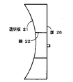
透明板21は、ユーザ9が当たった場合であっても安全であるように、強化ガラスやアクリルやポリカーボネート等を素材とする透明板であることが望ましい。さらに、撮影の際の照明20が反射しない構成を備える。具体的には、特殊表面加工を施すことによって、反射率を大幅に減少させた素材を用いた透明板21を用いることもできる。また、透明板21の形状を、図6および図7に示される形状とすることもできる。図6は背景2の上面図で、図7は側面図である。図6および図7に示されるように、透明板21が曲面を奏することで、反射光がカメラ10に到達することを防止することができ、反射光の写込まない美しい写真を得ることができる。なお、曲面の方向は、図6に示すように上から見て曲面を奏していてもよいし、図7に示すように横からみて曲面を奏していてもよい。また、その両方の形状を備えてもよい。
【0062】
さらに、透明板21は、図8に示す形状を奏してもよい。すなわち、分割された透明板21が角度をもって下(あるいは上)を向いている形状であってもよい。このようにすることでも、反射光の写込まない美しい写真を得ることができる。
【0063】
また、図5には図示されていないものの、本実施の形態における背景2として、透明板21の前にも背景被写体23が配されていてもよい。その場合、上述の如く、被写体90との接触や盗難のおそれ等あるため、このようなことの発生しないような配され方をされていることが望ましい。具体的には、透明板21に接着されたガラス製の風船や、図示しない映写装置等で投影される立体ホログラフィ等の背景被写体23を配することができる。なお、上述の立体ホログラフィを背景被写体23として配することで、任意の場所に表示することができ、任意の位置に背景被写体23を配することができる。また、被写体90に重ねて配することも可能である。そのため、より臨場感ある写真を得ることができる。また、このような背景被写体23を、カメラ10と被写体90との間に配することで、被写体90が背景被写体23である風船等を手に持ったような臨場感ある写真を得ることもできる。
【0064】
[第2の実施の形態]
次に、第2の実施の形態における写真自動販売機について説明を行なう。第2の実施の形態における写真自動販売機の外観および写真撮影装置1の構成については、第1の実施の形態におけるものと同様であるため、ここでは説明を繰返さない。
【0065】
次に、図9は、第2の実施の形態における背景2の具体例について示す図である。図9を参照して、本実施の形態における写真自動販売機は、背景2として、被写体90の背後に背景ディスプレイ27とその制御装置28とを備えることを特徴とする。なお、制御装置28は、図9に示される如く、写真撮影装置1と独立した装置であってもよいし、写真撮影装置1に含まれる装置であってもよい。後者の場合、背景ディスプレイ27の背後に制御装置28の設置スペースを設ける必要がなく、筐体3をよりコンパクトに設計することができる。
【0066】
図10は、背景ディスプレイ27と制御装置28との構成を示すブロック図である。図10を参照して、背景ディスプレイ27は、複数の発光素子、ネオンランプ、あるいは映像スクリーン等から構成され、制御装置28に制御されて様々な映像を表示する。
【0067】
制御装置28は、CPU(Central Processing Unit)等から構成され、制御装置28と背景ディスプレイ27とを制御する制御部201と、ユーザ9からの指示の入力を受付ける入力部204と、通信部203と、表示する情報等を記憶する記憶部202とを含む。
【0068】
本実施の形態において、ユーザ9は、予め制御装置28の記憶部202に記憶されている画像のうち、所望する画像を背景ディスプレイ27に表示させて、写真の背景とすることができる。このような背景ディスプレイ27に表示させる画像は、制御装置28の入力部204に直接入力することで指示してもよい。また、写真撮影装置1の入力装置41で入力することによって、写真撮影装置1から制御装置82の入力部204に入力された指示が渡されてもよい。また、制御装置28がインターネットや通信回線やLAN(Local Area Network)等を介して通信する通信部203を備える場合には、それらを介して他のサーバ等の記憶装置から、所望する画像データを取得して背景ディスプレイ27に表示してもよい。また、観光会社や遊戯を提供する会社等から、通信部203を介して、それらの業者が提供している商品等の画像を取得して背景ディスプレイ27に表示してもよい。
【0069】
このように、予め記憶部202に記憶させた画像や通信部203を介して取得した画像データを背景画像として背景ディスプレイ27に表示させることで、無限の種類の背景画像をユーザ9に提供することができ、ユーザ9にオリジナリティの高い写真を提供することが可能になる。
【0070】
なお、上述のように、制御装置28が写真撮影装置1に含まれる場合、制御装置28の制御部201の行なう制御手段を写真撮影装置1の制御部101が行なうことで、制御部201を制御部101に包含させることができる。同様に、記憶部202は記憶部102に包含させることができる。また、入力部204は操作部40に包含させることができ、ユーザ9は、操作部40を操作することで背景ディスプレイ27の表示を操作することができる。また、通信部203を写真撮影装置1内に備えることができる。そして、写真撮影装置1と背景ディスプレイ27とが通信を行なうことで画像データを互いに送受信し、背景ディスプレイ27に画像を表示させることができる。なお、ここでの通信は、LANやその他のインタフェース等を用いた通信回線による通信であってもよいし、無線による通信であってもよい。さらに、背景ディスプレイ27は、写真撮影装置1内の電源部(図示せず)から電源を得ることもできる。このようにすることで、装置の製造コストを大幅に削減することができる。
【0071】
なお、本実施の形態においても第1の実施の形態における写真自動販売機と同様に、背景ディスプレイ27の前にカーテン(図示せず)を備えることで、背景ディスプレイ27に表示される画像を背景としない写真を得たいというユーザ9のニーズに応えることもできる。また、第1の実施の形態における写真自動販売機と同様に、背景2の前に立体ホログラフィ等の背景被写体23を配することができる。このことによって、より臨場感ある写真を得ることができる。
【0072】
今回開示された実施の形態はすべての点で例示であって制限的なものではないと考えられるべきである。本発明の範囲は上記した説明ではなくて特許請求の範囲によって示され、特許請求の範囲と均等の意味および範囲内でのすべての変更が含まれることが意図される。
【図面の簡単な説明】
【図1】本実施の形態における写真自動販売機の外観の具体例を示す図である。
【図2】図1に示される写真撮影装置1の外観の具体例を示す図である。
【図3】図2に示される写真撮影装置1の構成を示す機能ブロック図である。
【図4】写真撮影装置1が備えられる本実施の形態の写真自動販売機において実行される処理を示すフローチャートである。
【図5】第1の実施の形態における背景2の具体例について示す図である。
【図6】透明板21の形状の具体例を示す図である。
【図7】透明板21の形状の具体例を示す図である。
【図8】透明板21の形状の具体例を示す図である。
【図9】第2の実施の形態における背景2の具体例について示す図である。
【図10】背景ディスプレイ27と制御装置28との構成を示すブロック図である。
【符号の説明】
1 写真撮影装置、2 背景、3 筐体、9 ユーザ、10 カメラ、10a上部カメラ、10b 下部カメラ、20 照明、20a 上部照明、20b 下部照明、21 透明板、22 棚、23 背景被写体、24 照明、25 カーテン、26 扉、27 背景ディスプレイ、28 制御装置、30 ディスプレイ、30a 上部ディスプレイ、30b 下部ディスプレイ、40 操作部、41 入力装置、50 コイン投入口、51コイン検出部、60 取出口、61 プリンタ、70 スピーカ、101 写真撮影装置の制御部、102 写真撮影装置の記憶部、103 グラフィックI/F回路、104サウンドI/F回路、105 画像補正部、106 画像合成部、107 表示選択回路、108 照明制御部、109 プリンタコントローラ、110 カウンタ、201制御装置の制御部、202 制御装置の記憶部、203 通信部、204 入力部。[0001]
TECHNICAL FIELD OF THE INVENTION
The present invention relates to a photographing apparatus, a photo vending machine, and a printing medium, and more particularly, to a photographing apparatus, a photo vending machine, and a printing medium that can provide a photograph using a background desired by a user.
[0002]
[Prior art]
A photo vending machine that automatically captures and prints the user's photo by inserting the value of coins, etc., and the user's image that has been captured and the image stored in advance and can be selected from the user Photo vending machines and the like that print a photo combined with a printed image are widely known.
[0003]
[Problems to be solved by the invention]
In such a conventional photo vending machine, a plurality of curtains with a printed background can be used as a background for photographing. Further, an illumination device can be provided behind the subject to change the color of the illumination light.
[0004]
Thus, although there is a photo vending machine that provides a user with a highly original background, there is a problem that it is not possible to provide a user with more types of backgrounds.
[0005]
Further, there is a problem that wrinkles and kinks easily occur in the above-described curtain, and a beautiful photograph cannot be provided in some cases with a background using the curtain. In addition, when an image printed on a flat surface is used as a background, there is a problem that there is a case where a three-dimensional effect is not obtained and a satisfactory photograph cannot be provided to a user.
[0006]
In addition, in order to provide more realistic pictures, technologies using chroma key technology, face or human body recognition technology, etc. have been adopted as image synthesis technology. It is impossible to perform a detailed synthesis such as between individual hairs, and there is a problem of lack of reality. In particular, in the case of a user who has a hair style with a lot of hair gaps, such as a sauvage or perm, the background can be seen through a gap between the hairs when actually photographing. Also, the background reflected through transparent clothing has the effect of appearing translucent. Such an effect is very difficult to be realized by the above-described image composition technique, and has a problem that it is difficult to provide a beautiful photograph with true reality.
[0007]
The present invention has been made in view of such a problem, and has an object to provide a photographing apparatus, a vending machine, and a print medium that can provide a beautiful photograph with a high originality. I do.
[0008]
[Means for Solving the Problems]
In order to achieve the above object, according to one aspect of the present invention, a photographing device is a photographing device including a photographing means for photographing a subject and a background, wherein the background includes a transparent plate and a transparent shelf. A background subject arranged in a space, wherein the photographing means photographs the subject and the background subject via the transparent plate.
[0009]
Further, the above-mentioned transparent shelf includes a plurality of transparent shelves, the background subject is a plurality of background subjects arranged on each of the plurality of transparent shelves, and the photographing unit performs the plurality of shooting in response to a user instruction. It is desirable to select one of the background subjects and shoot as the background subject.
[0010]
Further, it is preferable that the photographing device further includes an illuminating unit for illuminating the background subject, and the illuminating unit illuminates the background subject selected in accordance with a user's instruction.
[0011]
Further, it is desirable that the above-mentioned transparent plate has a function of preventing light reflected by the transparent plate from being photographed by the photographing means.
[0012]
Further, the function of preventing the light reflected on the transparent plate from being photographed is desirably a transparent plate shape such that the light reflected on the transparent plate does not reach the photographing means.
[0013]
According to another aspect of the present invention, a photographing device is a photographing device including photographing means for photographing a subject and a background, and the background is a display means.
[0014]
Further, it is desirable that the display means displays an image stored in advance in response to a user's instruction.
[0015]
Further, it is desirable that the display means displays an image using one of a plurality of light emitting elements, a neon lamp, and a video screen.
[0016]
Further, it is preferable that the photographing apparatus further includes a blocking unit that blocks the background so that the background is not photographed by the photographing unit.
[0017]
Further, it is preferable that the photographing device further includes a second subject between the photographing unit and the background, and the photographing unit photograph the subject, the background, and the second subject.
[0018]
Further, it is desirable that the second subject is a stereoscopic video.
According to still another aspect of the present invention, a photo vending machine includes the above-described photo-taking device, and printing means for printing a photo taken by the photo-taking device.
[0019]
According to still another aspect of the present invention, a print medium is a print medium used in a printing unit of the above-described photo vending machine.
[0020]
BEST MODE FOR CARRYING OUT THE INVENTION
Hereinafter, embodiments of the present invention will be described with reference to the drawings. In the following description, the same parts and components are denoted by the same reference numerals. Their names and functions are the same. Therefore, detailed description thereof will not be repeated.
[0021]
[First Embodiment]
First, the photo vending machine according to the first embodiment will be described.
[0022]
FIG. 1 is a diagram illustrating a specific example of the appearance of a photo vending machine according to the present embodiment.
[0023]
Referring to FIG. 1, the photo vending machine according to the present embodiment includes a photographing
[0024]
Behind the subject 90, a background 2, which is a background at the time of shooting, is provided. The background 2 will be described in detail later with a specific example.
[0025]
The color or pattern of the inner wall at the rear of the housing 3 is not limited as long as the photographing can be performed effectively. Specifically, when chroma key synthesis is performed, blue color is given. In addition, white may be applied to bring out the effect of indirect illumination, or pink, red, yellow, etc. may be applied in consideration of the effect of color (color cast) on the subject 90.
[0026]
FIG. 2 is a diagram showing a specific example of the appearance of the photographing
Referring to FIG. 2, an upper camera 10 a and a lower camera 10 b are provided in front of the photographing
[0027]
A
[0028]
The photographed image of the subject 90 is displayed on the
[0029]
Further, an
[0030]
According to an instruction from the user 9, the photographed image is printed on a print medium such as a card such as paper or plastic, a metal accessory, or the like, and is provided to the user 9 by being discharged from the
[0031]
Note that the
[0032]
FIG. 3 is a functional block diagram showing the configuration of the photographing
[0033]
Referring to FIG. 3, photographing
[0034]
The
[0035]
The graphic I / F (interface)
[0036]
The sound I /
[0037]
The image signal of the subject 90 sent from the camera 10 including the upper camera 10a and the lower camera 10b is received by the
[0038]
The image synthesis unit 106 receives an image signal of the subject 90 as a first image signal, and receives an image signal of a stored image transmitted from the graphic I /
[0039]
The
[0040]
The
[0041]
The
[0042]
The counter 110 counts and displays the number of coins inserted.
In a general photo vending machine equipped with such a photographing
[0043]
When the user 9 inserts a coin and a detection signal is transmitted from the
[0044]
FIG. 4 is a flowchart showing a process executed in the photo vending machine of the present embodiment provided with the photographing
[0045]
Referring to FIG. 4, first, when the required number of coins is received from user 9 while the demonstration screen is displayed,
[0046]
Subsequently, selection of a desired photographing method from the user 9 is received (S103). In the photographing
[0047]
Subsequently, selection of a desired background 2 from the user 9 is received (S104). In step S104, when the background 2 desired by the user 9 is selected, control is performed so that the background 2 is photographed. The method of controlling the desired background 2 will be specifically described later.
[0048]
When the photographing method and the background 2 selected in step S103 are determined, the subject 90 is photographed by the camera 10 (S105). The photographing process in step S105 may be performed a plurality of predetermined times. Further, it may be performed a plurality of times repeatedly within the time limit. At this time, an instruction to move the camera 10 can be received from the
[0049]
When the photographing in step S105 is completed, the photographed image is displayed on the
[0050]
When the input of the second image is completed in step S107, an image obtained by combining the image captured in step S105 and the above-described second image is displayed on the
[0051]
Further, the image to be printed selected in step S109 is displayed on the
[0052]
When the layout selection is received in step S111, the received layout and the image data of the image to be printed received in step S109 are transmitted to the
[0053]
Thus, the processing in the photographing
[0054]
The above is the description of the photo vending machine including the
[0055]
Next, the background 2 in the first embodiment will be described. FIG. 5 is a diagram illustrating a specific example of the background 2 according to the first embodiment. Referring to FIG. 5, the photo vending machine according to the present embodiment is characterized in that background 2 is provided using a show window type shelf. Specifically, the background 2 in the present embodiment is a background subject 23 that is photographed as a background of the subject 90 and is provided on a show window-type shelf including a transparent plate 21 and a transparent shelf 22. And
[0056]
The background subject 23 as the background 2 corresponds to a stuffed animal, a balloon, a plant, or the like. The background subjects 23 are placed on the shelf 22 and are projected onto the background of the subject 90 via the transparent plate 21 to become the background. As described above, since the background subject 23 such as a stuffed animal is put in the show window, the subject 90 does not interfere with the subject 90 during shooting, is broken, is stolen, or becomes dirty. . In addition, since a photograph can be taken with a three-dimensional object as a background, a detailed natural background combined photograph can be provided without the need for image combining. Therefore, it is possible to obtain a natural synthesized image that cannot be obtained by the image synthesis technology, and it is possible to provide a realistic photograph. Further, since the shelf 22 is transparent, a natural photograph in which the shelf 22 is not projected can be obtained. In addition, the present invention is not limited to a stationary object such as a stuffed animal, and a variety of photographs can be obtained by using an object such as a stuffed animal whose shape changes automatically or according to an instruction from the user 9 as the background subject 23.
[0057]
As shown in FIG. 5, the shelves 22 are provided in a plurality of stages, and a lighting 24 is provided above each of the shelves to illuminate a background subject 23 placed on each of the shelves 22. The user 9 can input an instruction from the
[0058]
In addition, an attendant or the like can open the
[0059]
The inside of the
[0060]
In addition, in order to meet the needs of the user 9 who wants to obtain a photograph not having the background 2 as the background, a non-transparent curtain 25 for blocking the background 2 is further provided in front of the transparent plate 21. Therefore, such a user 9 can take a photograph as usual by lowering the curtain 25 as shown in FIG. 5 and preventing (blocking) the background subject 23 from appearing.
[0061]
The transparent plate 21 is desirably a transparent plate made of tempered glass, acrylic, polycarbonate, or the like so that the transparent plate 21 is safe even when hit by the user 9. Further, a configuration is provided in which the
[0062]
Further, the transparent plate 21 may have the shape shown in FIG. That is, the divided transparent plate 21 may have a shape in which the transparent plate 21 faces downward (or upward) at an angle. By doing so, a beautiful photograph without reflected light can be obtained.
[0063]
Although not shown in FIG. 5, background object 23 may be arranged in front of transparent plate 21 as background 2 in the present embodiment. In this case, as described above, there is a risk of contact with the subject 90 or theft, and therefore it is desirable that the arrangement should be such that such a situation does not occur. Specifically, a background subject 23 such as a balloon made of glass adhered to the transparent plate 21 or a stereoscopic holography projected by a projection device (not shown) or the like can be arranged. By arranging the above-described three-dimensional holography as the background subject 23, it can be displayed at an arbitrary place, and the background subject 23 can be arranged at an arbitrary position. Further, it is also possible to dispose it on the subject 90 in an overlapping manner. Therefore, a more realistic photograph can be obtained. Further, by arranging such a background subject 23 between the camera 10 and the subject 90, it is possible to obtain a realistic photograph as if the subject 90 was holding a balloon or the like, which is the background subject 23. .
[0064]
[Second embodiment]
Next, a photo vending machine according to a second embodiment will be described. The external appearance of the photo vending machine and the configuration of the photographing
[0065]
Next, FIG. 9 is a diagram illustrating a specific example of the background 2 in the second embodiment. Referring to FIG. 9, the photo vending machine according to the present embodiment includes a
[0066]
FIG. 10 is a block diagram showing the configuration of the
[0067]
The control device 28 includes a CPU (Central Processing Unit) and the like, and controls the control device 28 and the
[0068]
In the present embodiment, the user 9 can display a desired image from among the images stored in the
[0069]
As described above, by displaying the image stored in the
[0070]
As described above, when the control device 28 is included in the photographing
[0071]
In this embodiment, similarly to the photo vending machine in the first embodiment, by providing a curtain (not shown) in front of the
[0072]
The embodiments disclosed this time are to be considered in all respects as illustrative and not restrictive. The scope of the present invention is defined by the terms of the claims, rather than the description above, and is intended to include any modifications within the scope and meaning equivalent to the terms of the claims.
[Brief description of the drawings]
FIG. 1 is a diagram showing a specific example of the appearance of a photo vending machine according to an embodiment.
FIG. 2 is a diagram showing a specific example of the appearance of the photographing
FIG. 3 is a functional block diagram showing a configuration of the photographing
FIG. 4 is a flowchart showing a process executed in the photo vending machine of the present embodiment provided with the
FIG. 5 is a diagram illustrating a specific example of a background 2 in the first embodiment.
FIG. 6 is a view showing a specific example of the shape of a transparent plate 21;
FIG. 7 is a view showing a specific example of the shape of a transparent plate 21;
FIG. 8 is a diagram showing a specific example of the shape of a transparent plate 21;
FIG. 9 is a diagram illustrating a specific example of a background 2 according to the second embodiment.
FIG. 10 is a block diagram showing a configuration of a
[Explanation of symbols]
1 photography apparatus, 2 backgrounds, 3 housings, 9 users, 10 cameras, 10a upper camera, 10b lower camera, 20 lighting, 20a upper lighting, 20b lower lighting, 21 transparent plate, 22 shelves, 23 background subject, 24 lighting , 25 curtain, 26 door, 27 background display, 28 control device, 30 display, 30a upper display, 30b lower display, 40 operation unit, 41 input device, 50 coin insertion slot, 51 coin detection unit, 60 outlet, 61 printer , 70 speakers, 101 control unit of the photographing device, 102 storage unit of the photographing device, 103 graphic I / F circuit, 104 sound I / F circuit, 105 image correction unit, 106 image synthesis unit, 107 display selection circuit, 108 Lighting control unit, 109 printer controller, 110 counter, 201 system The control unit of the device, the
Claims (13)
前記写真撮影装置で撮影された写真を印刷する印刷手段とを備える、写真自動販売機。A photographing device according to any one of claims 1 to 11,
A printing means for printing a photograph taken by the photographing device.
Priority Applications (1)
| Application Number | Priority Date | Filing Date | Title |
|---|---|---|---|
| JP2002158696A JP2004004223A (en) | 2002-05-31 | 2002-05-31 | Photographing device, photograph vending machine, and print media |
Applications Claiming Priority (1)
| Application Number | Priority Date | Filing Date | Title |
|---|---|---|---|
| JP2002158696A JP2004004223A (en) | 2002-05-31 | 2002-05-31 | Photographing device, photograph vending machine, and print media |
Publications (2)
| Publication Number | Publication Date |
|---|---|
| JP2004004223A true JP2004004223A (en) | 2004-01-08 |
| JP2004004223A5 JP2004004223A5 (en) | 2005-09-22 |
Family
ID=30428807
Family Applications (1)
| Application Number | Title | Priority Date | Filing Date |
|---|---|---|---|
| JP2002158696A Pending JP2004004223A (en) | 2002-05-31 | 2002-05-31 | Photographing device, photograph vending machine, and print media |
Country Status (1)
| Country | Link |
|---|---|
| JP (1) | JP2004004223A (en) |
Cited By (2)
| Publication number | Priority date | Publication date | Assignee | Title |
|---|---|---|---|---|
| JP2006227314A (en) * | 2005-02-17 | 2006-08-31 | Make Softwear:Kk | Automatic photographing apparatus |
| JP2006284623A (en) * | 2005-03-31 | 2006-10-19 | Omron Entertainment Kk | Apparatus and method for creating photograph sticker, recording medium and program |
-
2002
- 2002-05-31 JP JP2002158696A patent/JP2004004223A/en active Pending
Cited By (3)
| Publication number | Priority date | Publication date | Assignee | Title |
|---|---|---|---|---|
| JP2006227314A (en) * | 2005-02-17 | 2006-08-31 | Make Softwear:Kk | Automatic photographing apparatus |
| JP2006284623A (en) * | 2005-03-31 | 2006-10-19 | Omron Entertainment Kk | Apparatus and method for creating photograph sticker, recording medium and program |
| JP4656396B2 (en) * | 2005-03-31 | 2011-03-23 | フリュー株式会社 | Photo sticker creating apparatus and method, recording medium, and program |
Similar Documents
| Publication | Publication Date | Title |
|---|---|---|
| JP5802911B2 (en) | Photo game machine | |
| JP2005079662A (en) | Image editing method in photograph vending machine, photograph vending machine, and image editing program | |
| JP2005025027A (en) | Photograph vending machine and pose guiding method therefor | |
| JP2005181843A (en) | Photograph vending machine and control method and control program therefor | |
| JP2001100305A (en) | Photograph vending machine | |
| JP5334073B2 (en) | Photo shooting device | |
| JP2004357018A (en) | Photograph vending machine and photograph providing method in photograph vending machine | |
| JP4851985B2 (en) | Image display method, image display apparatus, image output apparatus, and computer program | |
| JP2003241296A (en) | Automatic vending method for photograph seal, equipment for the same, seal paper unit, and photographic seal sheet | |
| JP3852585B2 (en) | Photo sticker vending method and apparatus | |
| JP2004147174A (en) | Photograph vending machine, image input method, and image input program | |
| JP2004004223A (en) | Photographing device, photograph vending machine, and print media | |
| JP4215247B2 (en) | Automatic photo creation device | |
| JP2004159158A (en) | Method and device for providing photographic print | |
| JP3566706B2 (en) | Photo vending machine, control method for photo vending machine, control program for photo vending machine, and recording medium recording control program for photo vending machine | |
| JP2004170829A (en) | Photograph sticker creation method, its device, and sticker paper unit | |
| JP5013203B2 (en) | Photo sticker creation apparatus and method, and program | |
| JP2003177461A (en) | Photographing device and method | |
| JP6028246B2 (en) | Photo game machine | |
| JP2014202962A (en) | Photographing game machine and control program thereof | |
| JP3502946B2 (en) | Photo-seal automatic vending method and device, seal paper unit and photo-seal sheet | |
| JP2013239919A (en) | Photography game machine, photography game method and control program | |
| JP2004104685A (en) | Photographic apparatus | |
| JP2003177460A (en) | Photographing device and method | |
| JP3753064B2 (en) | Photo sticker vending method and apparatus |
Legal Events
| Date | Code | Title | Description |
|---|---|---|---|
| A521 | Written amendment |
Free format text: JAPANESE INTERMEDIATE CODE: A523 Effective date: 20050412 |
|
| A621 | Written request for application examination |
Effective date: 20050412 Free format text: JAPANESE INTERMEDIATE CODE: A621 |
|
| A977 | Report on retrieval |
Free format text: JAPANESE INTERMEDIATE CODE: A971007 Effective date: 20071129 |
|
| A131 | Notification of reasons for refusal |
Free format text: JAPANESE INTERMEDIATE CODE: A131 Effective date: 20071204 |
|
| A02 | Decision of refusal |
Free format text: JAPANESE INTERMEDIATE CODE: A02 Effective date: 20080408 |