JP2004001663A - Rail for sliding type two-wheeler parking facility, slide mechanism, and sliding type two-wheeler parking facility with the slide mechanism - Google Patents
Rail for sliding type two-wheeler parking facility, slide mechanism, and sliding type two-wheeler parking facility with the slide mechanism Download PDFInfo
- Publication number
- JP2004001663A JP2004001663A JP2002189459A JP2002189459A JP2004001663A JP 2004001663 A JP2004001663 A JP 2004001663A JP 2002189459 A JP2002189459 A JP 2002189459A JP 2002189459 A JP2002189459 A JP 2002189459A JP 2004001663 A JP2004001663 A JP 2004001663A
- Authority
- JP
- Japan
- Prior art keywords
- rail
- wheels
- sliding
- motorcycle
- parking facility
- Prior art date
- Legal status (The legal status is an assumption and is not a legal conclusion. Google has not performed a legal analysis and makes no representation as to the accuracy of the status listed.)
- Granted
Links
- 230000007246 mechanism Effects 0.000 title claims abstract description 28
- 230000003028 elevating effect Effects 0.000 claims description 3
- 230000000630 rising effect Effects 0.000 abstract description 3
- 239000000463 material Substances 0.000 description 25
- 210000002683 foot Anatomy 0.000 description 7
- 238000010586 diagram Methods 0.000 description 6
- 238000005096 rolling process Methods 0.000 description 4
- 239000000428 dust Substances 0.000 description 3
- 230000000694 effects Effects 0.000 description 3
- 238000009434 installation Methods 0.000 description 3
- 239000004576 sand Substances 0.000 description 3
- NJPPVKZQTLUDBO-UHFFFAOYSA-N novaluron Chemical compound C1=C(Cl)C(OC(F)(F)C(OC(F)(F)F)F)=CC=C1NC(=O)NC(=O)C1=C(F)C=CC=C1F NJPPVKZQTLUDBO-UHFFFAOYSA-N 0.000 description 2
- 238000004519 manufacturing process Methods 0.000 description 1
- 230000035939 shock Effects 0.000 description 1
- 210000003371 toe Anatomy 0.000 description 1
Images


Landscapes
- Bearings For Parts Moving Linearly (AREA)
Abstract
Description
【0001】
【発明の属する技術分野】
発明は、二輪車を狭いスペースに多数台詰めて駐車させることが出来る二輪車駐車設備に係り、更に詳しくは二輪車を隣り合う方向にスライドさせて詰めることが出来るスライド式二輪車駐車設備、また二輪車を上段の軌条部材に載せ上げて駐車スペースを確保する2段式二輪車駐車設備、また昇降装置を立体駐車場の下層階と上層階との間に架け渡して成る立体駐車場に係り、これ等のスライド式二輪車駐車設備のレール、スライド機構及びこのスライド機構を有するスライド式二輪車駐車設備に関するものである。
【0002】
【従来の技術】
従来より自転車の駐車収納設備として、横設したレール上を移動可能に並設した複数台の駐車部材から構成されたスライドラックなるものがあった。駐車部材は一般的に横断面コ字形状のチャンネル材から成り、その開放側が上に向くように置かれ、チャンネル材の下面の前後に設けた車輪を2本の平行なレールに填め合わせて左右にスライド自在と成るように構成したものである。このチャンネル材に自転車の前輪後輪を載せ上げて駐車させるが、自転車が載っている状態でも駐車部材はその車輪によりレール上を軽々とスライドすることが出来る。従って自転車を詰めて駐車させることが出来、また出庫する場合には隣り合って駐車している自転車をスライドさせて除けることが出来る、という利点がある。
【0003】
また従来より、下部駐車スペースを有し、支柱または該支柱で横設された支柱梁部材に一端部が取り付けられた上部駐車収納部材と、当該部材に対して回動及び摺動自在に枢支された可動軌条部材から成る上部駐車テーブルとによって構成され、前記上部駐車収納部材より可動軌条部材を引き出して傾斜保持させ、自転車の前後輪を可動軌条部材上に載置しつつ可動軌条部材の端部持ってこれを水平状態にして、上部駐車収納部材内に挿入することによって上部駐車テーブル上に自転車を駐車させる駐車装置が実用化されている。このものには、下部駐車スペースと上部駐車テーブルとの2段に自転車を駐車させることが出来るという特長がある。
【0004】
また従来より、下層階から上層階へ二輪車を移送するための傾斜路に沿って、二輪車搬送用のベルトコンベアを設置した立体駐車場が建設されている。下層階にも上層階にも二輪車を駐車させることが出来、ベルトコンベアによって上層階へ二輪車を移送するのが容易である。
【0005】
【発明が解決しようとする課題】
とは言うものの、スライド式の二輪車駐車装置に於いては、前記車輪とレールとの填め合わせ構造は極めて複雑である。一般的にレールは、駐車部材やそれに載置された自転車の重量を支えるための車輪を下から支える(垂直方向の力を支える)と共に、駐車部材がレールから外れることを防止すべく車輪の両側面方向からの接触を(水平方向の力を)受け支えしなくてはならないため、填め合わせ構造は複雑と成らざるを得ず、設置作業が難しかったりコストが高くついたりしている。従って、設置作業が容易でコストが低く成るようにしたい。
【0006】
また2段式駐車装置に於いては、可動軌条部材を自転車ごと上部駐車収納部材内に挿入して駐車させたり、可動軌条部材を自転車ごと上部駐車収納部材から引き出して出庫させるように操作する。この際可動軌条部材が円滑にスライドするようにしなくてはならないが、未だ不満を抱えている。従って、可動軌条部材が円滑にスライドするような仕組みを提供したい。
【0007】
またベルトコンベアを設置した立体駐車場に於いては、ベルトコンベアが蛇行したり振動するという問題がある。従って、コンベア機構が円滑にスライドするようにしたい。
【0008】
このようにこの発明は、上述のような問題点を解決して、円滑にスライド動作を行なわせなくては成らない二輪車駐車設備に関して、それを可能にすることを課題とするものである。
【0009】
【課題を解決するための手段及び作用】
上記の課題を解決すべく種々の案を試みた結果、レールに於ける車輪の転動面を傾斜させることによって、垂直方向から接触する車輪と水平方向から接触する車輪とを、実質的に一つの車輪で実現可能であるという知見を得た。
【0010】
即ち上記課題は、2条の立面部が略V字形状を呈しており且つ各々の立面部に付いてこれと略直角に車輪の滑走面部を備えていることを特徴とする、スライド式二輪車駐車設備のレールとすることによって達成される。なお2条の立面部は初めから一体に形成される場合と、各々別体の立面部2つを後から略V字形状を呈するように組み付ける場合とがある。これはレールの発明であるから、本構成にあっては車輪は必須要件ではないが、車輪と組み合わせたスライド機構の発明としては次のように構成される。
【0011】
即ち2条の立面部が略V字形状を呈しており且つ各々の立面部に付いてこれと略直角に車輪の滑走面部を備えて成るレールの、各々の滑走面部に接触して転動し得るように2つの車輪を配置し、該車輪を台車にて軸支し、この台車に二輪車の車輪通路を取り付け得るように構成したスライド式二輪車駐車設備のスライド機構である。二輪車の車輪通路とは上述した駐車部材のことであり、平板状通路やチャンネル材の開口部を上に向けたものなど任意である。また別途車輪支持枠などを取り付け得るように構成することが出来る。また車輪通路とは、上述した可動軌条部材やコンベアのことである。何れにせよ台車は駐車装置や設備の種類により各々に適合するように構成される。なお二輪車とは自転車、電動アシスト自転車、原動機付き自転車、バイクなどのことである。
【0012】
前記滑走面部に車輪を置くと車輪とレールとが一体化する。車輪は斜めの姿勢でレールの滑走面部に接触するため、台車の重量を垂直方向に支えて転動すると共に、台車のブレを水平方向に支えて転動することが出来る。従って、この発明のスライド機構により台車をいつでも円滑に軽々とスライドさせることが出来るように成っている。部品点数が多いと重量が重くなったり摩擦の増加を招いたりして製造上のマイナス要因となるが、この発明のスライド機構ではそのようなことが少なくなっている。
【0013】
次に上記課題は、2条の立面部が略V字形状を呈しており且つ各々の立面部に付いてこれと略直角に車輪の滑走面部を備えて成るレールの、各々の滑走面部に接触して転動し得るように2つの車輪を配置し、該車輪を台車にて軸支し、このようなレールと台車との組を2組、レールが平行と成るように設置し、この2つの台車間に架け渡すようにして二輪車の車輪通路を取り付けて成る、スライド式二輪車駐車設備とすることによって達成される。
【0014】
この構成では上述したスライド機構を2つ用意し、レールが平行と成るように設置し、2つの台車の上部を架け渡すようにして取り付けた二輪車の車輪通路を備えており、上記同様の作用を得る。
【0015】
また上記課題は、2条の立面部が略V字形状を呈しており且つ各々の立面部に付いてこれと略直角に車輪の滑走面部を備えて成るレールの、各々の滑走面部に接触して転動し得るように2つの車輪を配置し、該車輪を台車にて軸支し、前記レールを支柱または該支柱で横設された支柱梁部材在に取り付けて、前記台車に軌条部材を回動自在に軸支して成る、スライド式二輪車駐車設備とすることにより達成される。
【0016】
上段に横設したレールと台車とによってスライド機構が構成されており、この台車に軌条部材が回動自在に取り付けられて、自転車の上げ下げの際のスロープの役目を担うと共に、このスライド機構は軌条部材を奥まで入れたり出したりする動作を円滑なものにしている。
【0017】
また上記課題は、2条の立面部が略V字形状を呈しており且つ各々の立面部に付いてこれと略直角に車輪の滑走面部を備えて成るレールの、各々の滑走面部に接触して転動し得るように2つの車輪を配置し、該車輪を台車にて軸支し、前記レールと台車とを無端状に配設し、前記台車に毛先を対向させて二輪車の車輪を挟み込むようにした一対のブラシ様体を該台車の全周に渡って取り付け、このように構成した昇降装置を立体駐車場の下層階と上層階との間に架け渡して成る、スライド式二輪車駐車設備とすることにより達成される。なお当然のことながら台車はモータなどの駆動源によって駆動されるものである。
【0018】
この発明のスライド式二輪車駐車設備では、二輪車を牽引するための主要部が一対のブラシ様体から構成されるため比較的シンプルな構造であり、強固で安定した運用が可能と成っている。ブラシ様体の毛足は弾力性を有しているため、多少のタイヤの太さの違いを吸収することが出来、タイヤの挟持力も満足出来るものと成っている。なお、台車(無端搬送材)の移動方向に隣り合うブラシ様体の設置間隔は任意設計可能であるが、一対のブラシ様体は同期して動作することが望まれる。
【0019】
なおこの発明のレール、スライド機構、このスライド機構を有するスライド式二輪車駐車設備に関して、前記立面部に長手方向の突条部が形成されたものとすることが出来る。立面部は2条あるが、突条部の形成は少なくとも一側だけでよく、両側に形成するとなおよい。これは台車に水平方向の回転力が加わった場合などに、レールを転動する車輪が立面部壁面を擦って回転が止まり、台車のスライド動作が渋くなったり停止してしまうことを防止するのに一役買う構造と成っている。即ち上述したような場合でも、車輪はただこの突条部に接触するだけで立面部壁面には直接的には接触せず、摩擦もこの突条部との間にしか生じないからである。
【0020】
次に、前記立面部に付いてこれと略直角に天部が形成されたものとすることが出来る。この発明ではレールの立面部が略V字形状を呈しており、車輪も立面部と同様に、略V字形の取り付け角を有する構造であるため、台車が上方向へ引き上げられたような場合でも、車輪がレールから外れにくい性質を備えているが、天部の存在によって、更にこの傾向が強まり、車輪がレールから外れにくいものと成る。この他、車輪の転動部分に、利用者の足先や枯れ葉などのゴミが入りにくく成るようにするためのカバーを、レールの外側に設けるなどの工夫も好ましくある。
【0021】
【発明の実施の形態】
以下この発明の実施の形態に付き、図面を参照しながら説明するが、この発明はこの実施形態にのみ限定されるものではない。
【0022】
(第1実施形態)
図1乃至図3を用いてこの発明の第1実施形態の説明を行なう。図中符号1はレールであるが、このレールに付いて2つの立面部10が40度の開き角で略V字形状を呈するように立設されており、各々の立面部10の下端部からは滑走面部11が、また上端部からは天部12が立面部10に対して90度の角度で外方向へ設けられている。なお両の天部12は中央で連結されており、また両の滑走面部11は台座で連結されている。
【0023】
このような構成のレール1に対して台車2を、レール1の長手方向に滑走自在に組み付ける。即ち、台車2はその両端部に軸受け20を備え、該軸受け20の内側に車輪21が回転軸22により回転自在に取り付けられており、該車輪21が前記レール1の滑走面部11を転動し得るように、台車2をレール1に組み付けるのである。従って車輪21も前記立面部10と同様、略V字形の取り付け角を有する(図1及び図2を参照)。
【0024】
このようなレール1と台車2とから成るスライド機構を2つ、レール1が平行と成るように設置し、二輪車の車輪通路であるチャンネル材3を2つの台車2の上部に架け渡してスライド式二輪車駐車設備としている。図3ではレール1の上にチャンネル材3,31が載っている状態が表わされている。チャンネル材3,31は断面コ字形状を呈し、開口部が上方に向けられており、この溝に二輪車の車輪が案内され、駐車される。またチャンネル材3,31には前輪支持枠32が前記溝を挟むようにして立設されている。なお、チャンネル材31側は前記2つの台車2,2の受け具4,40間に架け渡されている。受け具4と受け具40とでは長さが異なり受け具4の方が長いため、チャンネル材31が傾斜した状態で表わされている。
【0025】
また図3では奥側に、前記受け具4を用いずに直接台車2上に固定したチャンネル材3を表わしている。このようなチャンネル材3,31の組を交互にレール1,1上に配置することによって、隣り合って駐車される自転車のハンドルが、入庫時や出庫時に干渉し難く成る。
【0026】
(第2実施形態)
次に図4で示したものは、上述の第1実施形態のレールとは少々異なり、前記立面部10に長手方向の突条部13を形成して成る点に特徴を有する。該立面部10は2条あり、突条部13はその各々の側に、車輪21に向き合うように形成されている。このように構成することによって、台車2に不本意な力が加わり、レール1を転動する車輪21が立面部10の壁面を擦るような状態に陥ったとしても、突条部13に接触するため、摩擦抵抗がある程度以上大きく成らないという利点がある。
【0027】
なお更にこの実施形態のレールには、前記立面部10に付いてこれと略直角に天部12が形成されている。従って車輪21がレール1からより外れにくいものと成っている。
【0028】
(第3実施形態)
次に図5で示したものは、レール1に台車2を組み付けた際に、回転部である車輪21を覆い隠すためのカバー部14が、レール1の最外側部に、レール1と一体に形成されている点に特徴を有する。
【0029】
従来のスライドラック式の二輪車駐車設備では、レールと車輪との填め合わせ構造は複雑であり、チャンネル材の開口部を水平方向に向けてレールを設置したりしているため、枯れ葉などのゴミや砂などが入りやすかった。しかしながらこの発明のレールでは、もともと転動面が傾斜しており、ゴミや砂が入っても自然に排出する傾向を有する。その上更にこの実施形態ではカバー部14を追加したというわけである。このように構成することによって、利用者の足先が車輪21に触れづらくこの部位に枯れ葉などのゴミや砂が入りにくい、という性質がより一層顕著なものと成っている。
【0030】
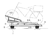
(第4実施形態)
次に図6で示したものは、各々1条分ずつの立面部16を備えたレール15を2つ合わせてボルト止めして、1つのレールを構成している点に特徴を有する。上述した第1実施形態のレール1では、2条の立面部10,10が一体に成形されていた。これに対して第4実施形態では、20度の傾斜角を持って立設された立面部16を備えた2つのレール15,15を立面部16,16で40度の開き角を呈するように組み合わせて成る。なお符号17は滑走面部を指す。
【0031】
このように、レールは引き抜き材として一体に成形したものでも、部分部分を組み合わせて形成したものでもよい。なおこの実施形態では立面部10の傾斜角を20度としたが、この数値に限定されるものではない。
【0032】
この形態に於いて、二輪車の車輪通路であるチャンネル材の配置に工夫を凝すことが出来る。図7及び図8はこの一例である。図7に示したものでは、チャンネル材の前端部が前方Aのラインに位置するものと後方Bのラインに位置するものとに分けて配設されている。この場合、レール1,1は二輪車の通路と平行に設けられており、このレール1,1に対してチャンネル材3,31がほぼ直角に取り付けられている。これと同様の効果は、図8で表わすように、平行なレール1,1に対して、チャンネル材3,31を斜角に配設することによっても実現し得る。チャンネル材の前端部分をレール1,1に平行と成るラインで揃えれば、必然的に前記A,Bのずれが生ずるからである。
【0033】
なおそもそもこれ等の実施形態は、スライドラックに関するものであるから、駐車される自転車のハンドル位置を利用者自身が加減することで、隣り合う自転車をより詰めることが出来る道理である。従って、平行なレール1,1に対してチャンネル材の前端部のラインを平行に設置するという構成もまた有効なものである。
【0034】
(第5実施形態)
さて図9及び図10で示した実施形態は、スライド式の二輪車駐車設備としては、上部駐車テーブル上に自転車を駐車させるための駐車装置に関するである。下部駐車部材は上側が開口された断面がコ字形状のチャンネル材60から成り、支柱6の側面部に固定されている。またチャンネル材60の両側には前輪支持枠61が立設されている。前記支柱6の頂部にはレール1が略水平に固定されており、レール1は2つの立面部10が40度の開き角で略V字形状を呈するように立設されており、各々の立面部10の下端部からは滑走面部11が、また上端部からは天部12が立面部10に対して90度の角度で外方向へ設けられている。なお両の滑走面部11は台座で連結されている。このレール1に対して台車23を、レール1の長手方向にスライド自在に組み付ける。即ち台車23はその両端部に軸受け20を備え、該軸受け20の内側に車輪21が回転軸22により回転自在に取り付けられており、該車輪21が前記レール1の滑走面部11を転動し得るように、台車2をレール1に組み付けるのである。従って車輪21も前記立面部10と同様、略V字形の取り付け角を有する。
【0035】
この台車23の上面部には2つの軸受け24が相対して設けられ、この軸受け24に、上側が開口された断面がコ字形状のチャンネル材5の一端部が、回動軸50を以って回動自在と成るように取り付けられている。またチャンネル材5の両側の軸受け24との間にはガスバネ54が置かれ、その一端部がチャンネル材5側の取付板53に、他端部が軸受け24側に固定されて、ガスバネ54が常にはチャンネル材5を上昇させるように設けられている。符号51はチャンネル材5の両側に立設された前輪支持枠を指し、符号52はチャンネル材5の他端部に設けた持手を指す。
【0036】
さてその使用法であるが、下部駐車部材への駐車に付いてはチャンネル材60に自転車の車輪を嵌め込んで押し入れるようにすれば良い。次に上部駐車テーブル上に自転車を駐車させるには、先ずチャンネル材5の持手52等を持って手前に引くと、台車23がレール1の上を転動して手前に移動し、レール1の端部に至るとチャンネル材5が台車23に対して回動可能に成るため、チャンネル材5を下げるようにすると、チャンネル材5が傾斜して保持される。この際前記ガスバネ54が付勢される。この状態で自転車の前輪をチャンネル材5上へ持ち上げて載せ(図10)、前輪が前輪支持枠51に収まるまで自転車を押し上げ、チャンネル材5の持手52を持ってこれを水平状態に成るまで持ち上げ、更にレール1の奥の方へ押すように操作する。この持ち上げに際しては、下ろす時に付勢されたガスバネ54の力が加わって、より少ない力で持ち上げが可能に成る。またレール1の奥の方へスライドさせる操作も、レール1と台車23との組み合わせにより軽く円滑に行なうことが出来るのである。
【0037】
(第6実施形態)
次に図11及び図12で示した実施形態は、スライド式の二輪車駐車設備としては、レール1と台車25との組み合わせを利用した昇降装置を下階ステップ7と上階ステップ70との間に架け渡して成る立体駐車場に関するである。即ち、車輪21を無端レール1に嵌め合わせた台車25を、無端レール1を1周するように配置し、図示しない駆動源によって無端レール1上をスライド移動し得るように取り付ける。台車25の上面部にはL字金具8を立設し、このL字金具8の垂直面に、基部80とこの基部80に植え込まれた毛足部81とから成るブラシを毛足部81が略水平と成るように取り付ける。このような無端レール1と台車25との組み合わせを一対、ブラシの毛足部81同士が対向するように且つ二輪車の車輪をしっかりと挟み付けることが出来るように、並行に設ける。ブラシの上方には毛足部81の辺りにスリット73が開口されたカバー板72が設けられている。このような昇降装置が下階ステップ7と上階ステップ70とを結ぶ階段71に添うようにして設けられている(図12)。
【0038】
なお、駆動源は図示しなかったが、L字金具8の背面部には無端チェーン9が取り付けられており、この無端チェーン9を例えば駆動端のスプロケットに噛合するなどの構成を取ればよく、任意の設計が可能である。
【0039】
前記スロープ状のカバー板72の中央部にはスリット73が開口されており、ここから内部のブラシの毛足部81を見ることが出来る。駆動源が作動して一対の台車25,25が駆動されると、ブラシが上昇する。従って二輪車のタイヤをカバー板72のスリット73から落とし込んで、左右のブラシの毛足部81の間に挟み込ませると、二輪車は立て支えられつつ上方へ搬送される。この間利用者は階段71を手ぶらで上がることが出来る。
【0040】
なおこの発明は上述した実施形態に限定されないから、この発明の思想を満す限りに於いてレールの種類や形状は任意でありその本数も自由である。また駐車部材そのものの種類も自由である。また駐車部材に前輪や後輪を落とし込むための段部や孔部を形成することが出来る。
【0041】
また例えば図3の場合では、隣り合うチャンネル材3,31の配置を左右反転させて互い違いと成るようにしても良い。また受け具4,40などの上面に振動を吸収するためのゴム材を取り付けても良い。同様に図10の場合では、レールの両端部に台車23が衝突する際のショックを和らげるためのゴム材を取り付けても良い。
【0042】
【発明の効果】
以上この発明は、2条の立面部が略V字形状を呈しており且つ各々の立面部に付いてこれと略直角に車輪の滑走面部を備えていることを特徴とする、スライド式二輪車駐車設備のレールとしたものである。またこの発明は、上記レールの、各々の滑走面部に接触して転動し得るように2つの車輪を配置し、該車輪を台車にて軸支し、この台車に二輪車の車輪通路を取り付け得るように構成して、スライド機構としたものである。またこの発明は、上記スライド機構を2つ、レールが平行と成るように設置して、二輪車の車輪通路を前記2つの台車の上部に架け渡して成るスライド式二輪車駐車設備としたものであり、また上記スライド機構を立体駐車装置の上段に出し入れする軌条部材に設けて成るスライド式二輪車駐車設備としたものであり、また上記スライド機構をコンベア式の昇降装置に応用して成るスライド式二輪車駐車設備としたものである。
【0043】
この結果、設置作業が容易でコストが安く可動部が円滑にスライドするように成るという効果を奏して、所期の目的を達成している。
【図面の簡単な説明】
【図1】第1実施形態の側面図である。
【図2】同実施形態の模式図である。
【図3】同実施形態の使用状態説明図である。
【図4】第2実施形態の側面図である。
【図5】第3実施形態の側面図である。
【図6】第4実施形態の側面図である。
【図7】この発明のレールの配置を表わす模式図である。
【図8】この発明のレールの配置を表わす模式図である。
【図9】第5実施形態の正面図である。
【図10】同実施形態の使用状態説明図である。
【図11】第6実施形態の断面図である。
【図12】同実施形態の使用状態説明図である。
【符号の説明】
1 レール
10 立面部
11 滑走面部
12 天部
13 突条部
14 カバー部
15 レール
16 立面部
17 滑走面部
18 無端レール
2 台車
20 軸受け
21 車輪
22 回転軸
23 台車
24 軸受け
25 台車
3 チャンネル材
30 前輪支持枠
31 チャンネル材
32 前輪支持枠
4 受け具
40 受け具
5 チャンネル材
50 回動軸
51 前輪支持枠
52 持手
53 取付板
54 ガスバネ
6 支柱
60 チャンネル材
61 前輪支持枠
7 下階ステップ
70 上階ステップ
71 階段
72 カバー板
73 スリット
8 L字金具
80 基部
81 毛足部
9 無端チェーン[0001]
TECHNICAL FIELD OF THE INVENTION
The present invention relates to a motorcycle parking facility that can park a large number of motorcycles in a narrow space and parks the motorcycles. More specifically, the present invention relates to a sliding motorcycle parking facility that can slide a motorcycle in an adjacent direction and pack the motorcycles. A two-stage motorcycle parking facility that secures a parking space by mounting it on a rail member, and a multi-story parking lot where a lifting device is bridged between the lower and upper floors of a multi-story parking lot. The present invention relates to a rail, a slide mechanism of a motorcycle parking facility, and a slide type motorcycle parking facility having the slide mechanism.
[0002]
[Prior art]
2. Description of the Related Art Conventionally, as a bicycle parking storage facility, there has been a slide rack composed of a plurality of parking members juxtaposed so as to be movable on a horizontally provided rail. The parking member is generally made of a channel material having a U-shaped cross section, and is placed so that an open side thereof faces upward. Wheels provided in front and behind the lower surface of the channel material are fitted to two parallel rails so that the left and right sides are formed. It is configured so that it can slide freely. The front and rear wheels of the bicycle are placed on the channel material for parking, and the parking member can slide lightly on the rails by the wheels even when the bicycle is on the bicycle. Therefore, there is an advantage that the bicycles can be packed and parked, and when leaving the parking lot, the bicycles parked next to each other can be slid and removed.
[0003]
Further, conventionally, an upper parking storage member having a lower parking space, one end of which is attached to a column or a column beam member laterally provided by the column, and a pivotally supported pivotally and slidably with respect to the member. And an upper parking table formed of a movable rail member. The movable rail member is pulled out of the upper parking storage member and held in an inclined state, and the front and rear wheels of the bicycle are placed on the movable rail member while the end of the movable rail member is placed. A parking device has been put to practical use in which a bicycle is parked on an upper parking table by holding the bicycle in a horizontal state and inserting the bicycle into an upper parking storage member. This vehicle has a feature that a bicycle can be parked in two steps, a lower parking space and an upper parking table.
[0004]
Conventionally, multi-story parking lots have been constructed in which a belt conveyor for transporting motorcycles is installed along a ramp for transferring motorcycles from a lower floor to an upper floor. The motorcycle can be parked on the lower floor and the upper floor, and it is easy to transfer the motorcycle to the upper floor by a belt conveyor.
[0005]
[Problems to be solved by the invention]
Nevertheless, in a sliding-type motorcycle parking device, the fitting structure between the wheels and the rails is extremely complicated. In general, the rails support the wheels to support the weight of the parking member and the bicycle mounted on it from below (support the vertical force), and also prevent the parking members from coming off the rails on both sides of the wheels. Since it is necessary to support the contact from the surface direction (horizontal direction force), the fitting structure must be complicated, and the installation work is difficult and costly. Therefore, it is desired that the installation work is easy and the cost is low.
[0006]
Further, in the two-stage parking device, the movable rail member is inserted into the upper parking storage member together with the bicycle to park the bicycle, or the movable rail member is pulled out of the upper parking storage member together with the bicycle to be taken out. At this time, the movable rail members must slide smoothly, but they are still dissatisfied. Therefore, it is desired to provide a mechanism in which the movable rail member slides smoothly.
[0007]
Further, in a multi-story parking lot where a belt conveyor is installed, there is a problem that the belt conveyor meanders and vibrates. Therefore, it is desired that the conveyor mechanism slides smoothly.
[0008]
As described above, an object of the present invention is to solve the above-described problems and to make it possible to provide a motorcycle parking facility that must perform a sliding operation smoothly.
[0009]
Means and Action for Solving the Problems
As a result of various attempts to solve the above-described problems, as a result of inclining the rolling surfaces of the wheels on the rails, the wheels contacting vertically and the wheels contacting horizontally are substantially reduced. I learned that it can be realized with one wheel.
[0010]
That is, the above problem is characterized in that the two raised surfaces have a substantially V-shape, and each of the raised surfaces is provided with a sliding surface of the wheel substantially at right angles to the sliding surface. This is achieved by using a rail for motorcycle parking equipment. Note that the two raised surfaces may be integrally formed from the beginning, or may be assembled such that two separate raised surfaces are formed to have a substantially V-shape later. Since this is the invention of the rail, the wheel is not an essential requirement in this configuration, but the invention of the slide mechanism combined with the wheel is configured as follows.
[0011]
That is, the two raised surfaces have a substantially V-shape, and the rails provided with the running surfaces of the wheels at substantially right angles to the respective raised surfaces are brought into contact with the respective running surfaces to roll. This is a slide mechanism of a slide-type motorcycle parking facility in which two wheels are arranged so as to be movable, the wheels are pivotally supported by a truck, and a wheel passage of the motorcycle can be attached to the truck. The wheel passage of the motorcycle refers to the above-described parking member, and may be an arbitrary one such as a flat passage or an opening with a channel material facing upward. Further, it can be configured such that a wheel support frame or the like can be separately attached. The wheel passage means the above-mentioned movable rail member or conveyor. In any case, the trolley is configured to be adapted to each type of parking device and equipment. Note that a motorcycle refers to a bicycle, an electrically assisted bicycle, a motorized bicycle, a motorcycle, or the like.
[0012]
When a wheel is placed on the sliding surface, the wheel and the rail are integrated. Since the wheels come into contact with the sliding surface of the rail in an oblique posture, they can roll while supporting the weight of the bogie in the vertical direction and can also support the bogie of the bogie in the horizontal direction. Therefore, the carriage can be slid smoothly and lightly at any time by the slide mechanism of the present invention. If the number of parts is large, the weight increases and friction increases, which is a negative factor in manufacturing. However, such a problem is reduced in the slide mechanism of the present invention.
[0013]
Next, the above-mentioned problem is solved by the problem that the two raised surfaces have a substantially V-shape, and the respective sliding surfaces of the rails are provided with the running surfaces of the wheels at substantially right angles to the respective raised surfaces. Two wheels are arranged so as to be able to contact and roll, and the wheels are pivotally supported by a trolley; two sets of such rails and trolleys are installed such that the rails are parallel; This is achieved by providing a slide-type motorcycle parking facility in which a wheel passage of the motorcycle is attached so as to bridge between the two bogies.
[0014]
In this configuration, the two slide mechanisms described above are provided, the rails are installed so as to be parallel to each other, and a wheel passage of a two-wheeled vehicle mounted so as to bridge over the upper portions of the two bogies is provided. obtain.
[0015]
In addition, the above-mentioned problem is caused by the fact that the two raised surfaces have a substantially V-shape and that each of the raised surfaces has a running surface of a wheel substantially at right angles to each of the running surfaces of the rail. Two wheels are arranged so as to be able to contact and roll, and the wheels are pivotally supported by a bogie, and the rail is attached to a column or a column beam member laterally provided by the column, and a rail is attached to the column. This is achieved by providing a slide-type two-wheeled vehicle parking facility in which members are rotatably supported.
[0016]
A slide mechanism is constituted by a rail and a carriage laid horizontally on the upper stage, and a rail member is rotatably attached to this carriage, and plays a role of a slope when lifting and lowering the bicycle, and the slide mechanism is a rail mechanism. The operation of moving members in and out is smooth.
[0017]
In addition, the above-mentioned problem is caused by the fact that the two raised surfaces have a substantially V-shape and that each of the raised surfaces has a running surface of a wheel substantially at right angles to each of the running surfaces of the rail. Two wheels are arranged so as to be able to contact and roll, the wheels are pivotally supported by a bogie, the rail and the bogie are arranged endlessly, and the tip of the bogie is opposed to the bogie so that A pair of brush-like bodies that sandwich the wheels are attached around the entire periphery of the bogie, and the lifting device configured as described above is bridged between the lower floor and the upper floor of the multi-story parking lot, a sliding type. Achieved by using motorcycle parking facilities. It should be noted that the truck is driven by a drive source such as a motor.
[0018]
In the sliding motorcycle parking facility of the present invention, the main part for towing the motorcycle is composed of a pair of brush-like bodies, so that it has a relatively simple structure, and strong and stable operation is possible. Since the brush-like body has elasticity, it can absorb a slight difference in the thickness of the tire, and the pinching force of the tire can be satisfied. The interval between the brush bodies adjacent to each other in the moving direction of the carriage (endless conveying material) can be arbitrarily designed, but it is desired that the pair of brush bodies operate synchronously.
[0019]
The rail, the slide mechanism, and the slide-type two-wheeled vehicle parking facility having the slide mechanism according to the present invention may be configured such that a longitudinal ridge is formed on the upright surface. Although there are two raised portions, the ridges need only be formed on at least one side, and more preferably on both sides. This prevents the wheels that roll on the rail from rubbing against the wall surface of the vertical surface and stopping rotation, for example, when a horizontal rotational force is applied to the bogie, thereby preventing the bogie's sliding operation from becoming bitter or stopped. It is structured to play a role. That is, even in the case described above, the wheel only comes into contact with the ridge and does not directly contact the wall surface of the upright portion, and friction occurs only between the ridge and the ridge. .
[0020]
Next, a top portion may be formed on the upright portion substantially at right angles thereto. In the present invention, the raised surface of the rail has a substantially V-shape, and the wheels have a substantially V-shaped mounting angle similarly to the raised surface, so that the bogie is lifted upward. Even in this case, the wheels have the property of being hard to be detached from the rails. However, this tendency is further enhanced by the presence of the top portion, and the wheels are less likely to be detached from the rails. In addition, it is also preferable to provide a cover on the outside of the rail to prevent dust such as a user's toes or dead leaves from entering the rolling portion of the wheel.
[0021]
BEST MODE FOR CARRYING OUT THE INVENTION
Hereinafter, an embodiment of the present invention will be described with reference to the drawings, but the present invention is not limited to this embodiment.
[0022]
(1st Embodiment)
A first embodiment of the present invention will be described with reference to FIGS. In the figure,
[0023]
The
[0024]
Two slide mechanisms including such a
[0025]
FIG. 3 shows the
[0026]
(2nd Embodiment)
Next, what is shown in FIG. 4 is slightly different from the rail of the above-described first embodiment, and is characterized in that a
[0027]
Still further, the rail of this embodiment has a
[0028]
(Third embodiment)
Next, what is shown in FIG. 5 is that, when the
[0029]
In conventional slide rack type motorcycle parking equipment, the fitting structure of rails and wheels is complicated, and the rails are installed with the channel material opening horizontally oriented, so that garbage such as dead leaves and Sand was easy to enter. However, in the rail of the present invention, the rolling surface is originally inclined, and there is a tendency that dust or sand is naturally discharged even if it enters. Furthermore, in this embodiment, the
[0030]
(Fourth embodiment)
Next, what is shown in FIG. 6 is characterized in that two
[0031]
As described above, the rail may be formed integrally as a drawing material or may be formed by combining partial parts. In this embodiment, the inclination angle of the
[0032]
In this embodiment, the arrangement of the channel material, which is the wheel passage of the motorcycle, can be devised. FIG. 7 and FIG. 8 are examples of this. In the example shown in FIG. 7, the front end of the channel material is arranged separately into one located on the front A line and one located on the rear B line. In this case, the
[0033]
Since these embodiments relate to a slide rack in the first place, it is reasonable that the user can adjust the handle position of the parked bicycle by himself / herself so that the adjacent bicycles can be packed more. Therefore, a configuration in which the line at the front end of the channel material is installed in parallel with the
[0034]
(Fifth embodiment)
The embodiment shown in FIGS. 9 and 10 relates to a parking device for parking a bicycle on an upper parking table as a sliding type motorcycle parking facility. The lower parking member is made of a
[0035]
Two
[0036]
Now, as for the usage, when parking in the lower parking member, the bicycle wheel may be fitted into the
[0037]
(Sixth embodiment)
Next, in the embodiment shown in FIG. 11 and FIG. 12, as a sliding type motorcycle parking facility, an elevating device using a combination of the
[0038]
Although the drive source is not shown, an
[0039]
A
[0040]
Note that the present invention is not limited to the above-described embodiment, and the type and shape of the rail are arbitrary and the number of rails is free as long as the idea of the present invention is satisfied. Also, the type of the parking member itself is also free. Further, a step portion or a hole portion for dropping the front wheel or the rear wheel into the parking member can be formed.
[0041]
For example, in the case of FIG. 3, the arrangement of the
[0042]
【The invention's effect】
As described above, the present invention is characterized in that the two vertical surfaces have a substantially V-shape, and each of the vertical surfaces is provided with a sliding surface portion of the wheel substantially at right angles to the vertical surface. It is a rail for motorcycle parking facilities. Further, according to the present invention, two wheels are arranged so as to be able to roll in contact with the respective sliding surface portions of the rail, the wheels are supported by a bogie, and a wheel passage of a two-wheeled vehicle can be attached to the bogie. This is configured as a slide mechanism. Further, the present invention provides a sliding motorcycle parking facility in which two slide mechanisms are installed such that rails are parallel to each other, and a wheel passage of the motorcycle is bridged over the two bogies. In addition, the slide mechanism is provided as a slide type motorcycle parking facility provided on a rail member which is moved in and out of an upper stage of the multi-story parking device, and the slide mechanism is applied as a conveyor type lift apparatus to a slide type motorcycle parking facility. It is what it was.
[0043]
As a result, there is an effect that the installation section is easy, the cost is low, and the movable portion slides smoothly, thereby achieving the intended purpose.
[Brief description of the drawings]
FIG. 1 is a side view of a first embodiment.
FIG. 2 is a schematic diagram of the embodiment.
FIG. 3 is an explanatory diagram of a use state of the embodiment.
FIG. 4 is a side view of the second embodiment.
FIG. 5 is a side view of the third embodiment.
FIG. 6 is a side view of the fourth embodiment.
FIG. 7 is a schematic diagram showing an arrangement of rails according to the present invention.
FIG. 8 is a schematic diagram showing an arrangement of rails according to the present invention.
FIG. 9 is a front view of the fifth embodiment.
FIG. 10 is an explanatory diagram of a use state of the embodiment.
FIG. 11 is a sectional view of a sixth embodiment.
FIG. 12 is an explanatory diagram of a use state of the embodiment.
[Explanation of symbols]
DESCRIPTION OF
Claims (11)
Priority Applications (1)
| Application Number | Priority Date | Filing Date | Title |
|---|---|---|---|
| JP2002189459A JP4264697B2 (en) | 2002-03-29 | 2002-06-28 | Sliding motorcycle parking facilities |
Applications Claiming Priority (2)
| Application Number | Priority Date | Filing Date | Title |
|---|---|---|---|
| JP2002132167 | 2002-03-29 | ||
| JP2002189459A JP4264697B2 (en) | 2002-03-29 | 2002-06-28 | Sliding motorcycle parking facilities |
Publications (3)
| Publication Number | Publication Date |
|---|---|
| JP2004001663A true JP2004001663A (en) | 2004-01-08 |
| JP2004001663A5 JP2004001663A5 (en) | 2006-01-19 |
| JP4264697B2 JP4264697B2 (en) | 2009-05-20 |
Family
ID=30447583
Family Applications (1)
| Application Number | Title | Priority Date | Filing Date |
|---|---|---|---|
| JP2002189459A Expired - Fee Related JP4264697B2 (en) | 2002-03-29 | 2002-06-28 | Sliding motorcycle parking facilities |
Country Status (1)
| Country | Link |
|---|---|
| JP (1) | JP4264697B2 (en) |
Cited By (2)
| Publication number | Priority date | Publication date | Assignee | Title |
|---|---|---|---|---|
| WO2014081165A1 (en) * | 2012-11-22 | 2014-05-30 | Park Byung Chul | Sliding-type bicycle parking rack |
| WO2017207724A1 (en) * | 2016-06-02 | 2017-12-07 | Patrick Schiller Und Constanze Kocherscheidt Gbr | Holding device for bicycles, bicycle holding device, and method for parking a bicycle in a held position |
-
2002
- 2002-06-28 JP JP2002189459A patent/JP4264697B2/en not_active Expired - Fee Related
Cited By (2)
| Publication number | Priority date | Publication date | Assignee | Title |
|---|---|---|---|---|
| WO2014081165A1 (en) * | 2012-11-22 | 2014-05-30 | Park Byung Chul | Sliding-type bicycle parking rack |
| WO2017207724A1 (en) * | 2016-06-02 | 2017-12-07 | Patrick Schiller Und Constanze Kocherscheidt Gbr | Holding device for bicycles, bicycle holding device, and method for parking a bicycle in a held position |
Also Published As
| Publication number | Publication date |
|---|---|
| JP4264697B2 (en) | 2009-05-20 |
Similar Documents
| Publication | Publication Date | Title |
|---|---|---|
| JP2001020550A (en) | Bicycle parking device | |
| US7496983B2 (en) | Gymnasium floor covering storage and cleaning roller | |
| FR2677696A1 (en) | Car park structure provided with a number of independent levels | |
| KR101529135B1 (en) | folding electric drive board | |
| JP2004001663A (en) | Rail for sliding type two-wheeler parking facility, slide mechanism, and sliding type two-wheeler parking facility with the slide mechanism | |
| CN206457145U (en) | A kind of trolley aids in device upstairs | |
| JP6174621B2 (en) | Caster device for level difference | |
| KR101515196B1 (en) | Bicycle holding apparatus for vehicle | |
| CH640797A5 (en) | Storage installation comprising carriages which can be moved in two directions | |
| JP3966526B2 (en) | Bicycle parking facilities | |
| JP7228929B1 (en) | bicycle parking machine | |
| CN210000364U (en) | An underground supermarket goods transport device | |
| KR101433579B1 (en) | Mechanical parking apparatus | |
| JP3100378B1 (en) | Traveling rack traveling wheel device | |
| JP2000129947A (en) | Bicycle parking facility | |
| JP5087728B2 (en) | Elevator for motorcycle | |
| KR101782500B1 (en) | Cart conveying device of cart washing machine | |
| JP2005273150A (en) | Lifting device for motorcycle | |
| JP2000129947A5 (en) | ||
| JP4573202B2 (en) | Elevator for motorcycle | |
| JP2008074539A5 (en) | ||
| TWI408074B (en) | A bicycle rack | |
| CN213322812U (en) | Supporting plate for transporting road roller | |
| JP2002114180A (en) | Bicycle parking device | |
| JP2008195368A (en) | One wheel slide type bicycle parking equipment |
Legal Events
| Date | Code | Title | Description |
|---|---|---|---|
| A521 | Written amendment |
Free format text: JAPANESE INTERMEDIATE CODE: A523 Effective date: 20050628 |
|
| A621 | Written request for application examination |
Free format text: JAPANESE INTERMEDIATE CODE: A621 Effective date: 20050628 |
|
| A521 | Written amendment |
Free format text: JAPANESE INTERMEDIATE CODE: A523 Effective date: 20050928 |
|
| A521 | Written amendment |
Free format text: JAPANESE INTERMEDIATE CODE: A523 Effective date: 20051017 |
|
| A977 | Report on retrieval |
Free format text: JAPANESE INTERMEDIATE CODE: A971007 Effective date: 20070326 |
|
| A131 | Notification of reasons for refusal |
Free format text: JAPANESE INTERMEDIATE CODE: A131 Effective date: 20070410 |
|
| A521 | Written amendment |
Free format text: JAPANESE INTERMEDIATE CODE: A523 Effective date: 20070425 |
|
| A02 | Decision of refusal |
Free format text: JAPANESE INTERMEDIATE CODE: A02 Effective date: 20080527 |
|
| A521 | Written amendment |
Free format text: JAPANESE INTERMEDIATE CODE: A523 Effective date: 20080626 |
|
| A521 | Written amendment |
Free format text: JAPANESE INTERMEDIATE CODE: A523 Effective date: 20080728 |
|
| A911 | Transfer of reconsideration by examiner before appeal (zenchi) |
Free format text: JAPANESE INTERMEDIATE CODE: A911 Effective date: 20081117 |
|
| TRDD | Decision of grant or rejection written | ||
| A01 | Written decision to grant a patent or to grant a registration (utility model) |
Free format text: JAPANESE INTERMEDIATE CODE: A01 Effective date: 20090106 |
|
| A01 | Written decision to grant a patent or to grant a registration (utility model) |
Free format text: JAPANESE INTERMEDIATE CODE: A01 |
|
| A61 | First payment of annual fees (during grant procedure) |
Free format text: JAPANESE INTERMEDIATE CODE: A61 Effective date: 20090203 |
|
| R150 | Certificate of patent (=grant) or registration of utility model |
Free format text: JAPANESE INTERMEDIATE CODE: R150 |
|
| FPAY | Renewal fee payment (prs date is renewal date of database) |
Free format text: PAYMENT UNTIL: 20150227 Year of fee payment: 6 |
|
| LAPS | Cancellation because of no payment of annual fees |