JP2003127608A5 - - Google Patents

Download PDF

Info

Publication number
JP2003127608A5
JP2003127608A5 JP2001323856A JP2001323856A JP2003127608A5 JP 2003127608 A5 JP2003127608 A5 JP 2003127608A5 JP 2001323856 A JP2001323856 A JP 2001323856A JP 2001323856 A JP2001323856 A JP 2001323856A JP 2003127608 A5 JP2003127608 A5 JP 2003127608A5
Authority
JP
Japan
Prior art keywords
support hole
ring
state
diameter
knuckle
Prior art date
Legal status (The legal status is an assumption and is not a legal conclusion. Google has not performed a legal analysis and makes no representation as to the accuracy of the status listed.)
Granted
Application number
JP2001323856A
Other languages
Japanese (ja)
Other versions
JP2003127608A (en
JP3960005B2 (en
Filing date
Publication date
Application filed filed Critical
Priority to JP2001323856A priority Critical patent/JP3960005B2/en
Priority claimed from JP2001323856A external-priority patent/JP3960005B2/en
Publication of JP2003127608A publication Critical patent/JP2003127608A/en
Publication of JP2003127608A5 publication Critical patent/JP2003127608A5/ja
Application granted granted Critical
Publication of JP3960005B2 publication Critical patent/JP3960005B2/en
Anticipated expiration legal-status Critical
Expired - Fee Related legal-status Critical Current

Links

Images

Description

上記内側、外側両係合溝45、46及び止め輪44の寸法を上述の様に規制する為、この止め輪44を内側係合溝45部分に装着した状態で、上記外輪3aを上記ナックル30の支持孔32に挿入すれば、前記車輪用軸受ユニット1aと上記ナックル30とを不離に結合できる。即ち、上記外輪3aをこのナックル30に対し結合する場合には、上記止め輪44を上記内側係合溝45部分に装着した状態で、上記外輪3aを上記支持孔32に、外側から内側に、図1、2の左から右に挿入する。この挿入作業により上記止め輪44は、上記支持孔32の外端部に形成した円すい凹面状のガイド面48に案内されつつ、外径が弾性的に縮められて、上記支持孔32内に押し込まれる。そして、上記止め輪44と外側係合溝46とが整合した状態で、この止め輪44の直径が、この止め輪44の外周縁が上記外側係合溝46の底面に当接する状態迄、弾性的に広がる。そして、この様に止め輪44の直径が弾性的に広がった状態で、この止め輪44が上記内側、外側両係合溝45、46同士の間に掛け渡された状態になって、上記外輪3aが上記支持孔32から抜け出る事が防止され、上記車輪用軸受ユニット1aとナックル30とが不離に結合される。 In order to restrict the dimensions of the inner and outer engagement grooves 45 and 46 and the snap ring 44 as described above, the outer ring 3a is mounted on the knuckle 30 with the snap ring 44 attached to the inner engagement groove 45. The wheel bearing unit 1a and the knuckle 30 can be coupled together indiscriminately by being inserted into the support hole 32 of FIG. That is, when the outer ring 3a is coupled to the knuckle 30, the outer ring 3a is attached to the support hole 32 from the outer side to the inner side in a state where the snap ring 44 is attached to the inner engagement groove 45. Insert from left to right in Figures 1 and 2. By this insertion operation, the retaining ring 44 is guided by the conical concave guide surface 48 formed at the outer end of the support hole 32, and its outer diameter is elastically contracted and pushed into the support hole 32. Be In a state where the aforementioned retaining ring 44 and the outer engagement grooves 46 are aligned, the diameter of the retaining ring 44, the outer peripheral edge of the retaining ring 44 until the abutting state on the bottom of the outer engagement grooves 46, It spreads elastically. Then, in a state in which the diameter of the snap ring 44 is elastically expanded in this manner, the snap ring 44 is in a state of being stretched between the inner and outer engagement grooves 45, 46, and the outer ring It is prevented that 3a slips out of the support hole 32, and the wheel bearing unit 1a and the knuckle 30 are coupled together in an invariable manner.

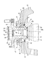
上記ナックル30に車輪用軸受ユニット1aを結合する場合には、上記止め輪54を上記内側係合溝45部分に装着した状態で、上記第一、第二各腕部56、57を上記凹入部47に整合させつつ、上記外輪3aを上記支持孔32に、外側から内側に、図7の左から右に挿入する。この挿入作業に伴って、上記止め輪54は、上記支持孔32の外端部に形成した円すい凹面状のガイド面48に案内されつつ、本体部55の外径が上記支持孔32の内径以下に弾性的に縮められて、この支持孔32内に押し込まれる。そして、上記本体部55と外側係合溝46とが整合した状態で、この本体部55の直径が、この本体部55の外周縁が上記外側係合溝46の底面に当接する状態に迄、弾性的に広がる。そして、この様に本体部55の直径が弾性的に広がった状態で、この本体部55が上記内側、外側両係合溝45、46同士の間に掛け渡された状態になって、上記外輪3aが上記支持孔32から抜け出る方向に変位する事が防止され、車輪用軸受ユニット1aとナックル30とが不離に結合される。 When the wheel bearing unit 1a is coupled to the knuckle 30, the first and second arm portions 56 and 57 are engaged with the recessed portion while the snap ring 54 is attached to the inner engagement groove 45. while matched to 47 a, the outer ring 3a in the support hole 32, from the outside to the inside, is inserted from left to right in FIG. With the insertion operation, the retaining ring 54 is guided by the conical concave guide surface 48 formed at the outer end of the support hole 32, and the outer diameter of the main body 55 is smaller than the inner diameter of the support hole 32. And is compressed into this support hole 32. Then, in a state where the main body portion 55 and the outer engagement groove 46 are aligned, the diameter of the main body portion 55 is such that the outer peripheral edge of the main body portion 55 abuts on the bottom surface of the outer engagement groove 46, It spreads elastically. Then, in a state in which the diameter of the main body portion 55 is elastically expanded in this manner, the main body portion 55 is in a state of being bridged between the inner and outer engagement grooves 45 and 46 and the outer ring The displacement of the wheel 3a in the direction of coming out of the support hole 32 is prevented, and the wheel bearing unit 1a and the knuckle 30 are coupled together in an indelible manner.

JP2001323856A 2001-10-22 2001-10-22 Rotation support device for wheels Expired - Fee Related JP3960005B2 (en)

Priority Applications (1)

Application Number Priority Date Filing Date Title
JP2001323856A JP3960005B2 (en) 2001-10-22 2001-10-22 Rotation support device for wheels

Applications Claiming Priority (1)

Application Number Priority Date Filing Date Title
JP2001323856A JP3960005B2 (en) 2001-10-22 2001-10-22 Rotation support device for wheels

Publications (3)

Publication Number Publication Date
JP2003127608A JP2003127608A (en) 2003-05-08
JP2003127608A5 true JP2003127608A5 (en) 2005-06-09
JP3960005B2 JP3960005B2 (en) 2007-08-15

Family

ID=19140681

Family Applications (1)

Application Number Title Priority Date Filing Date
JP2001323856A Expired - Fee Related JP3960005B2 (en) 2001-10-22 2001-10-22 Rotation support device for wheels

Country Status (1)

Country Link
JP (1) JP3960005B2 (en)

Families Citing this family (6)

* Cited by examiner, † Cited by third party
Publication number Priority date Publication date Assignee Title
JP4877904B2 (en) * 2005-07-27 2012-02-15 Ntn株式会社 Drive wheel bearing device and axle module including the same
JP4637723B2 (en) * 2005-11-08 2011-02-23 Ntn株式会社 Sliding constant velocity universal joint
JP5101051B2 (en) * 2006-06-22 2012-12-19 Ntn株式会社 Drive wheel bearing unit
JP2010091055A (en) * 2008-10-09 2010-04-22 Ntn Corp Chain tensioner
JP6041388B2 (en) * 2013-04-16 2016-12-07 日本オイルポンプ株式会社 Hydraulic motor
JP2020193668A (en) * 2019-05-28 2020-12-03 本田技研工業株式会社 Removal method of bearing

Similar Documents

Publication Publication Date Title
USD461827S1 (en) One-piece plastic protector and seal for a fluid cylinder shaft
USD453703S1 (en) Ring
US6382051B1 (en) Ratchet wrench
TW200613648A (en) Plug/socket assembly
USD904862S1 (en) Telescoping link
USD486174S1 (en) Eyeglass retainer
USD555726S1 (en) Writing implement
JP2003127608A5 (en)
USD516902S1 (en) End cap for curtain rod
US5943923A (en) Retaining device of socket spanner
USD495060S1 (en) Chromatography column assembly end cap
USD438840S1 (en) Sunroof for automotive vehicle
USD479799S1 (en) Edge protector
USD465186S1 (en) Automotive wheel
USD527104S1 (en) Vascular tubing
USD443930S1 (en) Rectal insertion device
USD506223S1 (en) Globe and stand
USD471565S1 (en) Engagement arrangement of two connectable bodies
USD488116S1 (en) Automotive wheel
USD434851S (en) Indirect ophthalmoscopy lens straight retaining ring
USD495232S1 (en) Pull
USD567946S1 (en) Vascular tube
USD473523S1 (en) Convoluted tubing with an overmolded end cap
USD432484S (en) Automotive wheel
USD996964S1 (en) Clip