【書類名】明細書
【発明の名称】ドップラーシフトした信号の周波数不確定範囲を絞り込むシステム及び方法
【特許請求の範囲】
【請求項1】 下記を具備する、検知されたパイロット信号の周波数不確定の範囲を狭めるためのシステム:
複数の周波数仮説の各々に関して複数のチップ上の検知されたパイロット信号のサンプルをコヒーレント的に累算するための手段、
前記累算されたパイロット信号サンプルに関するエネルギーを測定するための手段、
エネルギー累算値(EAV)を生成するために、複数の前記エネルギー測定値を累算するための手段、及び
複数の周波数仮説の中のいずれが最も高いEAVになるかを決定するための手段。
【請求項2】 前記決定するための手段は下記を具備する、請求項1のシステム:
現在の周波数仮設を、先行する前記周波数仮説の最大のEAVと比較する手段、ここにおいて、前記現在の周波数仮説EAVが前記最大のEAVより大きい場合には、それから、
前記最大EAVは、将来の周波数仮説により生成される複数のEAV
との比較のために、前記現在の周波数仮説EAVにより置換される、及
び
前記現在の周波数仮説は格納され、及び前記最大のEAVに対応する周波数仮説を置換する。
【請求項3】 検知されたパイロット信号はスペクトル拡散信号であり、そして適当なPNシーケンスで前記サンプルを乗算することにより前記パイロット信号サンプルを逆拡散するための手段をさらに具備する、請求項1のシステム。
【請求項4】 前記PNシーケンスで乗算される前に少なくとも2セットのパイロット信号サンプルを形成するための手段をさらに具備し、ここで、少なくとも前記サンプルの1セットは前記サンプルの他のセットに比して時間内でシフトされる、請求項3のシステム。
【請求項5】 前記PNシーケンスで乗算される前に少なくとも2セットのパイロット信号サンプルを形成するための手段をさらに具備し、ここで前記サンプルの1セットは時間通りのサンプルセットであり、そして前記サンプルの他のセットは遅いサンプルセットであり、ここで前記遅いサンプルセットは前記時間通りのサンプルセットに比して チップだけ時間内でシフトされる、請求項3のシステム。
【請求項6】 現在の周波数仮説により、検知されたパイロット信号の周波数をシフトするための手段をさらに具備し、ここで前記現在の周波数仮説は前記複数の周波数仮説の内の1である、請求項1のシステム。
【請求項7】 前記複数の周波数仮説上で前記現在の周波数仮説を増加するための手段をさらに具備する請求項6のシステム。
【請求項8】 検知されたパイロット信号の周波数をシフトする前に、検知されたパイロット信号をアナログ信号からディジタル信号に変換するための手段をさらに具備する、請求項6のシステム。
【請求項9】 シフトするための前記手段は、コンプレックス・ロテータである、請求項8のシステム。
【請求項10】 検知されたパイロット信号の周波数をシフトした後で、検知されたパイロット信号をアナログ信号からディジタル信号に変換するための手段をさらに具備する、請求項6のシステム。
【請求項11】 コード・ドップラー・タイミングエラーを訂正するための手段をさらに具備する、請求項1のシステム。
【請求項12】 前記パイロット信号サンプルと前記PNシーケンスとの間のコード・ドップラー・タイミング・エラーを訂正するための手段をさらに具備する請求項3のシステム。
【請求項13】 訂正するための前記手段は、コード・ドツプラー・タイミング・エラーを訂正するために所望されるように前記PNシーケンスのタイミングを調整するための手段を具備する、請求項12のシステム。
【請求項14】 訂正するための前記手段は下記を具備する、請求項12のシステム:
前記パイロット信号サンプルと前記PNシーケンスとの間のコード・ドツプラ-・タイミング・エラーの累算をモニターするための手段、
必要に応じてコード・ドツプラ-・タイミング・エラーを訂正するために前記PNシーケンスのタイミングを調整するための手段。
【請求項15】 前記モニターするための手段は、コード・ドツプラ-・エラー推定に基づいている、請求項14のシステム。
【請求項16】 前記コード・ドツプラ-・エラー推定は、検知されたパイロット信号を含む既知の周波数ビンの最後の周波数に基づいている請求項15のシステム。
【請求項17】 前記コード・ドツプラ-・エラー推定は、検知されたパイロット信号を含む既知の周波数ビン内の周波数に基づいてる、請求項15のシステム。
【請求項18】 シフトするための前記手段は、コンプレックス・ロテータとダイレクト・ディジタル・シンセサイザとを具備し、ここで前記ダイレクト・ディジタル・シンセサイザは周波数塁算器により制御される、請求項7のシステム。
【請求項19】 下記工程を具備する、検知されたパイロット信号の周波数不確定の範囲を狭めるための方法:
(1)複数の周波数仮説の各々に関する複数のチップ上の検知されたパイロット信号のサンプルをコヒーレントイ累算する、
(2)前記累算されたパイロット信号サンプルに関するエネルギーを測定する、
(3)エネルギー累算値(EVA)を生成するために複数の前記エネルギー測定値を累算する、
(4)複数の周波数仮説のうちのいずれが最も高いEVAになるかを決定する。
【請求項20】 工程(4)が更に下記を具備する、請求項19の方法:
現在の周波数仮説に関する前記EAVを、先行する周波数仮説の最大EVAと比較する、ここで前記現在の仮説EVAが前記最大のEAVより大きい場合には、それから、
a)将来の周波数仮説により生成される複数のEAVとの比較のために前記現在の周波数仮説EAVにより前記最大のEAVを置換する、
b)前記現在の周波数仮説を格納し、前記最大のEAVに対応する周
波数仮説を置換する。
【請求項21】 検知されるパイロット信号は、スペクトル拡散信号であり、PNシーケンスにより前記サンプルを乗算することにより前記パイロット信号サンプルを逆拡散する工程をさらに具備する、請求項19の方法。
【請求項22】 前記PNシーケンスにより乗算される前にパイロット信号サンプルの少なくとも2セットを形成する工程をさらに具備し、ここで前記サンプルの少なくとも1セットは、前記サンプルの他のセットに比して時間内にシフトされる、請求項21の方法。
【請求項23】 前記PNシーケンスにより乗算される前にパイロット信号サンプルの少なくとも2セットを形成する工程をさらに具備し、ここで前記サンプルの1セットは時間とおりのサンプルセットであり、前記サンプルの他のセットは遅いサンプルセットであり、ここで前記遅いサンプルセットは前記時間通りのサンプルセットに秘してチップだけ時間内でシフトされる、請求項21の方法。
【請求項24】 現在の周波数仮説により、検知されたパイロット信号の周波数をシフトする工程をさらに具備し、ここで前記現在の周波数仮説は前記複数の周波数仮説の一つである、請求項19の方法。
【請求項25】 前記複数の周波数仮説上で現在の周波数仮説を増加する工程をさらに具備する、請求項24の方法。
【請求項26】 検知されたパイロット信号の周波数をシフトする前に、検知されたパイロット信号をアナログ信号からディジタル信号に変換する工程をさらに具備する、請求項24の方法。
【請求項27】 検知されたパイロット信号の周波数をシフトした後で、検知したパイロット信号をアナログ信号からディジタル信号に変換する工程をさらに具備する、請求項24の方法。
【請求項28】 コード・ドツプラ-・タイミング・エラーを訂正する工程をさらに具備する、請求項19の方法。
【請求項29】 コード・ドツプラ-・タイミング・エラーを訂正する工程をさらに具備する、請求項21の方法。
【請求項30】 コード・ドツプラ-・タイミング・エラーを訂正する前記工程は、コード・ドツプラ-・エラーを訂正することの所望時に前記PNシーケンスのタイミングを調整する工程を具備する、請求項29の方法。
【請求項31】 コード・ドツプラ-・タイミング・エラーを訂正する前記工程は、下記工程を具備する請求項29の方法:
(1)前記パイロット信号サンプルと前記PNシーケンスとの間のコード・ドツプラ-・タイミング・エラーの累算をモニターする、及び
(2)コード・ドツプラ-・タイミング・エラーを訂正することの必要時に前記PNシーケンスのタイミングを調整する。
【請求項32】 モニターする前記工程は、コード・ドツプラ-・エラー推定に基づいている、請求項31の方法。
【請求項33】 前記コード・ドツプラ-・エラー推定は、検知されたパイロット信号を含む既知の周波数ビンの最後の周波数に基づいている、請求項32の方法。
【請求項34】 前記コード・ドツプラ-・エラー推定は、検知されたパイロット信号を含む既知の周波数ビン内の周波数に基づいている、請求項32の方法。
【発明の詳細な説明】
【0001】
【発明の属する技術分野】
本発明は、一般的には、無線通信システムに関し、より具体的には、未知ではあるが有限のドップラーシフト量を持つ、検出されたパイロット信号の周波数不確定の範囲(the range of frequency uncertainty)を狭めるシステムに関する。
【0002】
【従来の技術】
多数のシステムユーザ間で情報を伝送するために、様々な多重アクセス通信システムおよび技術が開発されている。しかし、符号分割多重アクセス(CDMA)スペクトル拡散技術のようなスペクトル拡散変調技術は、特に多数の通信システムユーザに対してサービスを提供する場合に、他の変調スキームを越える重要な利点を提供する。多重アクセス通信システムにおいてCDMA技術を用いることは、1990年2月13日に発行された米国特許第4,901,307号「衛星または地上中継器を用いたスペクトル拡散多重アクセス通信システム(Spread Spectrum Multiple Access Communication System Using Satellite Or Terrestrial Repeaters)」、および1997年11月25日に発行された米国特許第5,691,974号「個々の受信側位相、時間およびエネルギーを追跡するためのスペクトル拡散通信システムにおける全スペクトルの送信パワーを使用するための方法および装置(Method And Apparatus For Using Full Spectrum Transmitted Power In A Spread Spectrum Communication System For Tracking Individual Recipient Phase Time And Energy)」に開示されている。これらの特許は共に本発明の譲受人に譲渡されており、また、本明細書中に援用される。
【0003】
これらの特許は、多数の、一般的な移動体または遠隔の、システムのユーザまたは加入者ユニット(「ユーザ端末」)が、公衆電話交換ネットワーク(public telephone switching network)のような、他の接続されたシステムのユーザ、或いは他のユーザ端末と通信するための少なくとも1つのトランシーバー用いる通信システムを開示している。通信信号は、衛星中継器およびゲートウェイのいずれかを通して、あるいは直接、地上基地局(時に、セルサイト(cell−sites)またはセル(cells)とも呼ばれる)に転送される。
【0004】
現代の衛星通信システムにおいて、タイミングは決定的である。例えば、これらのシステムは、典型的に、通信チャネルを、それぞれのフレームが既知の持続時間(duration)を有する複数の「フレーム」に分割する。信号またはデータを伝送する際にこれらのフレームの利用を最適化するためには、ゲートウェイまたは基地局およびユーザ端末が、同期を確実にとるための何らかの方法を採用しなければならない。従って、各ユーザ端末には、タイミング基準を与えるための装置が設けられる。理想的な時間基準は、既知の周波数の信号をユーザ端末に与える。
【0005】
ユーザ端末においてタイミング基準を与えるために、しばしばローカル発振器が用いられる。しかし、完璧なローカル発振器はない。ローカル発振器は、周波数ドリフト(frequency drift)を受ける。ローカル発振器の周波数がドリフトすると、同期が失われる。
【0006】
ローカル発振器の周波数ドリフトを最低限に抑えるための1つのアプローチは、より高精度のローカル発振器を製造することである。しかし、そのような非常に安定したローカル発振器は、製造するのに非常に高価であり、ユーザ端末のコストを許容できない程高くしてしまう可能性がある。
【0007】
セルラー電話システムにおいて広く利用されている別のアプローチは、電圧制御温度補償水晶発振器(VTCXO)を含んでいる。VTCXOの出力周波数は、VTCXOへの入力電圧を変化させることによって制御できる。VTCXOは、温度変化に起因する周波数ドリフトに対して非常に強い。
【0008】
このようなセルラー電話システムにおいては、各ユーザ端末にVTCXOが設けられる。各ユーザ端末は、基地局から送信されるパイロット信号をモニタする。ユーザ端末は、パイロット信号の周波数をタイミング基準として利用して、印加される入力電圧を変化させることによってVTCXOの出力周波数を調節する。セルラー電話システムにおいては、基地局とユーザ端末の間の相対速度が小さいので、このようなアプローチを利用することができる。
【0009】
しかし、低地球軌道(LEO)衛星通信システムのようないくつかの衛星通信システムの場合、衛星とユーザ端末の間の相対放射速度(radial velocity)は非常に大きくなり得る。この大きな相対放射速度は、LEO衛星が送信するパイロット信号に大きなドップラーシフトを強いる。このために、上記技術がタイミング基準として不正確で潜在的に使用不可能なものになる。衛星が周波数ftで信号を送信した場合、受信信号周波数frは、下記のようになるであろう。
fr=ft±fD (1)
fD=ft・[V/c] (2)
但し、V=受信機に対する送信機の速度
c=適当な媒体中での光の速度
fD=ドップラー周波数シフト
【0010】
衛星がユーザ端末の方に行く場合には、電磁波の周期は短縮され、上記等式において[+]符号を用いる。衛星がユーザ端末から離れて行く場合には、電磁波は延ばされ、[−]を用いる。ドップラー効果はドップラー比[V/c]で表され得る。但し、Vは受信機に対する送信機の速度であり、cは適当な媒体中での光の速度である。ドップラー周波数シフトの大きさは、ドップラー比にftを掛けたものである。
【0011】
ドップラーシフトは、LEO衛星システムにおいては特に顕著である。例えば、典型的なLEO衛星の速度は、ユーザ端末に対して7km/秒になり得る。これは結果的に、送信機周波数が2.5GHzの場合、百万分の23の率(または23ppm)のドップラー比、および58kHz(以下の等式2で計算)のドップラー周波数シフトになる。
【0012】
ドップラー周波数シフトが存在し、デジタルデータストリームを送信するといつも、符号ドップラーエラー(code Doppler error)が生じる。符号ドップラーエラーは、送信機が受信機の方に或いは離れる方に移動することにより、送信機ビットレートに対して受信機ビットレートが上下するために生じる。符号ドップラーエラーは、ドップラー比[V/c]に送信機ビットレートを掛けたものである。結果的に得られる受信機側でのビットレートは、送信機ビットレートに符号ドップラーエラーを足した/引いたものである。但し、送信機が受信機の方に移動する場合には[+]符号を用い、送信機が受信機から離れる方に移動する場合には[−]符号を用いる。この関係は、下記の式で示される。
rr=rt±rD (3)
rD=rt・[V/c] (4)
但し、rrは受信機ビットレート
rtは送信機ビットレート
rDは符号ドップラーエラー、
Vおよびcは上記等式1と同様。
【0013】
符号ドップラーエラーは、疑似ノイズ(PN)発生器の同期に対して累算的な影響を与えるため、スペクトル拡散通信システムでは特に有害である。通常のスペクトル拡散通信システムの場合、1組の予め選択された疑似ノイズ(PN)符号シーケンスを用いて、搬送波信号を変調する前に所定のスペクトルバンド上でデジタルメッセージを変調(即ち、「拡散」)する。スペクトル拡散受信機がこの信号を正しく「逆拡散(despread)」するには、ローカルPN発生器のチッピング(chipping)またはチップレート(chip rate)(チップを発生させるレート)が受信信号チップレートと時間的に同期していなければならない。[「チップ(chip)」は、単一のPN符号ビットを指す業界用語である。PN符号チップを用いて拡散したデジタルメッセージ(音声、データなど)もまた、「チップ」を含んでいると言われることがあるが、「シンボル(symbol)」が好ましい。]受信信号チップレートが1Hzよりも小さな単位である場合、クロックエラーが経時的に累算して、PNシーケンスを入来するビットストリームとの同期を崩させれることになる。例えば、入来チップレートとローカルPN発生器の間に0.1Hzのオフセットは、結果的に毎秒0.1チップのタイミングエラーとなり、これは1分間に6チップ分のタイミングエラーに累算する。即ち、受信信号は、適当なPNシーケンスによって正しく逆拡散されるためにあるべき場所から6チップ分シフトすることになる。ある信号を正しく逆拡散するためには、スペクトル拡散受信機は符号位相ドリフトが半チップ周期未満である必要がある。エラーが1チップ分よりも大きいと、役に立たない情報を産することになる。従って、スペクトル拡散受信機において符号ドップラーエラーをモニタおよび補正することが重要である。
【0014】
【発明の概要】
本発明は、パイロット信号が未知ではあるが、有界の量のドップラーシフトを有する衛星通信システムにおいて、検出されたパイロット信号の周波数不確定の範囲を狭めるシステムおよび方法に関する。パイロット信号検出の期間に、情報を得て、下側および上側周波数によって境界が定められた周波数ビン(frequency bin)内にパイロット信号を入れる。本発明は、この周波数ビン内の複数の周波数仮説(frequency hypotheses)によって、検出されたパイロット信号をシフトさせ、その後、どの仮説が最大エネルギー累算値を有するのかを決定する。最大エネルギー累算値を有する仮説が、このパイロット信号の真の中心周波数に最も近い仮説である。一般的に、結果として得られる周波数識別力(frequency discrimination)のレベルは、下側および上側周波数間において試される周波数仮説の数によってのみ制限される。しかし、パイロット信号がスペクトル拡散信号である場合、試される仮説の数とエネルギー累算値の精度との間には、トレードオフの関係がある。要するに、符号ドップラーエラーは、スペクトル拡散パイロット信号と、そのパイロット信号を逆拡散するために用いられる疑似ノイズ(PN)符号シーケンスとの間の時間的な同期を失わせる。タイミングエラーは処理時間(または試される仮説値の数)と共に増加し、補正されなければ、以降の周波数仮説についてのエネルギー累算値を誤らせることになる。
【0015】
本発明は、符号ドップラータイミングエラーを補正するために2つの改良を取り入れている。第1に、符号ドップラーエラーを、検出されたパイロット信号を含んでいることが分かっている周波数ビンの最終周波数に基づいて推定する。本発明では、複数の周波数仮説にわたってタイミングエラーの累算をモニタし、タイミングエラーが、パイロット信号の正確な逆拡散ができなくなるおそれのあるレベルに達する前に同期の喪失を補正する。この補正は、その公称レートに対してPNシーケンス発生のタイミングまたはチップレートを進めるあるいは遅らせることによって行われる。
【0016】
符号ドップラーエラーの計算は、パイロット信号が周波数ビンの上側周波数に位置しているという仮説に基づいており、推定に過ぎない。実際には、パイロット信号が周波数ビン内のどこにあるのかは分からない。従って、上記補正は、複数の周波数仮説にわたってパイロット信号を正確に逆拡散するために必要な同期量を保証するものではない。符号ドップラーエラーの影響をさらに低減するために、本発明では、それぞれの周波数仮説の期間に、2組の検出されたパイロット信号を並行して逆拡散する。一方のパイロット信号組を「時間どおり(On−Time)」と表記し、一方のパイロット信号組を「遅い(Late)」と表記する。遅延組は、時間どおりのサンプル組に対して時間的に半チップ周期分遅れてサンプリングされる。一方の組が他方に対して時間的にシフトしている2組のパイロット信号サンプルを並行して逆拡散することにより、本発明は、1つのサンプル組のみを処理する場合と比較して、複数の周波数仮説値にわたる同期タイミングエラーを全体的に低減している。これは、遅いサンプル組が、パイロット信号周波数ビンの中央部にあるそれらの仮説における最小タイミングエラーとなり、他方、時間どおりサンプル組が、周波数ビンの境界付近のそれらの仮説について最小タイミングエラーとなるからである。
【0017】
図面を参照しながら以下の詳細な説明を読むことにより、本発明の特徴、目的および利点がより明白になるであろう。全図面を通して、同様の参照符号は対応する部材を指している。
【発明の開示】
I.はじめに
本発明は、低地球軌道(LEO)衛星を使用する通信システムでの使用に特に適している。しかし、当業者に明らかなように、本発明の概念は通信目的で利用していない衛星システムにも応用できる。本発明は、衛星が非LEO軌道を航行する衛星システムまたは非衛星基本のシステムにも応用できる。
【0018】
本発明の好ましい実施例を以下説明する。特定のステップ、形態、構造について述べるが、これは本発明を説明するためだけであることを理解されたい。当業者は、他のステップ、形態、構造が本発明の趣旨と範囲を越えることなく用いることができる旨を認識できよう。本発明は、位置決定に目標を置いたシステムを含む種々の無線情報と通信システム、及び衛星及び地上セルラ電話システムで使用できる。好ましい適用対象として、電話サービス用CDMA無線拡散スペクトラム通信システムがある。
【0019】
II.代表的な衛星通信システム
本発明が有用となる例示的な無線通信システムの一例を図1に示す。この通信システムはCDMA型通信信号を使うものと考える。だが本発明によれば、そうである必要はない。図1に示す通信システム100の一部において、一つの基地局112と、二つの衛星116と118、二つの関連ゲートウェイ、すなわちハブ120と122を用いて、二つの遠隔地にあるユーザ端末124と126との通信を達成する。代表的には、基地局と衛星/ゲートウェイとは、地上及び衛星ベースと呼ばれる別個の通信システムの構成部分である。しかし、そうである必要はない。このようなシステム中の基地局と、ゲートウェイ、衛星の総数は、当該分野で周知の通り、システムの所望能力と他の要因に依存する。
【0020】
ユーザ端末124と126は、各々セルラ電話、データトランシーバ、ページング、あるいは位置決定用受信器などの無線通信機を含む。ただし、無線通信機は例示したこれらのものに限らない。そして、必要に応じ、無線受信器は手持ち型と車両搭載型のいずれかであり得る。ここでは、ユーザ端末を、それぞれ手持ち型124と車両搭載型126として図示する。しかし、本発明の教示内容が、固定式機器や遠隔無線サービスが望まれる場所に設置の機器に応用可能であることが理解される。ここで言う場所とは、「野外」はもちろん「室内」も指す。
【0021】
一般に、衛星116と118からのビームは予め定めたパターンで区画された、異なる地表地域をカバーする。異なる周波数のビームは、CDMAチャンネルあるいは「サブビーム」呼ばれ、同一地域に、重なる状態で発信される。複数個の衛星に関するサービス地域及びビームカバレージ、或いは複数個の基地局に関するアンテナパターンは、通信システムの設計仕様と、提供されるサービスの種類、空間ダイバーシチ達成の可否に依存して、全体的にあるいは部分的に重なるように設計できることは当業者であれば容易に理解できよう。
【0022】
異なる8つの軌道平面内のLEO軌道を航行する衛星を約48個以上使って、多数のユーザ端末をサービスする様々なマルチ衛星通信システムが提案されている。また、他の軌道距離と配置を有する様々な衛星通信システムとゲートウェイ形態にも、本発明の教示内容が応用可能である旨を当業者ならば理解できよう。同時に、本発明は種々の基地局形態の地上設置システムにも同様に適用可能である。
【0023】
図1において、ユーザ端末124と126と、基地局112との間の通信、または衛星116と118とを介した通信を実施可能とするための信号通路をいくつか、ゲートウェイ120と122と共に示す。基地局―ユーザ端末通信リンクを、線130および132で示す。衛星116、118と、ユーザ端末124、126との間の衛星―端末通信リンクを、線140と、142、144で示す。ゲートウェイ120、122と、衛星116、118との間の、ゲートウェイー衛星間通信リンクを、線146,148、150、152で示す。ゲートウェイ120、122と基地局112とは単一方向または双方向通信システムの一部として、あるいは単にメッセージやデータをユーザ端末124と126とに送信するために使用しても良い。
【0024】
ユーザ端末106内で使用するためのトランスシーバ200を一つ図2に例示する。このトランスシーバ200は、通信信号を受け取るための、少なくとも一本のアンテナ210を有する。アンテナ210が受けた信号はアナログ受信器214へ送られ、ダウンコンバートされ、増幅され、デジタル化される。デュプレクサ素子212を代表的に用いて、同じアンテナが送信と受信、双方の機能を果たすようにしている。しかし、システムによっては、異なる送信周波数と受信周波数で作動する別個のアンテナを用いる。
【0025】
アナログ受信器214が出力するデジタル通信信号が、少なくとも一つのデジタルデータ受信器216Aと、少なくとも一つの探索受信器218とに送られる。装置の複雑性(complexity)の許容レベルによるが、デジタルデータ受信器216B乃至216Nを付加的に用いて、所望レベルの信号ダイバーシチを得ることが可能である。当業者には明らかな通りである。
【0026】
少なくとも一台のユーザ端末の制御プロセッサ220がデジタルデータ受信器216A〜216Nおよび探索受信器218に連結される。制御プロセッサ220は様々な機能の中でも信号処理、タイミング、電力、ハンドオフの基本的な制御や協調、信号搬送波に用いられる周波数の選択の機能を提供する。制御プロセッサ220がしばしば行う別の基本的な制御機能は、通信信号波形の処理に用いられる擬似ランダム雑音(PN)コード列や直交関数の選択や操作である。制御プロセッサ220による信号処理には、相対的な信号強度の決定や、様々な関連信号パラメータの演算を含めることができる。タイミングや周波数などの信号パラメータのそのような演算には、測定の効率や速度を改善したり、制御処理資源の割り当てを改善したりするために、別個に追加した専用回路を使用しても構わない。
【0027】
デジタルデータ受信器216A〜216Nの出力は、ユーザ端末内のデジタルベースバンド回路222に連結される。ユーザデジタルベースバンド回路222は、ユーザ端末のユーザと情報を遣り取りするための処理やプレゼンテーション用の素子を備えている。すなわち、信号やデータの記憶素子、例えば、一時記憶や長期記憶のためのデジタルメモリ、入出力装置、例えば、ディスプレースクリーン、スピーカ、キーボード、送受話器、A/D素子、ボコーダその他の音声信号やアナログ信号を処理する素子等々の総てが、この技術分野では良く知られている素子を用いたユーザデジタルベースバンド回路222の部品を構成する。ダイバーシティ信号処理を採用するのであれば、ユーザデジタルベースバンド回路222にダイバーシティコンバイナおよびデコーダを組み込んでも良い。これらの素子の幾つかは制御プロセッサ220と交信して作動する。すなわち、制御プロセッサ220の制御の下で作動する。
【0028】
ユーザ端末から生じる出力メッセージや通信信号として音声等のデータが準備されると、送信に望ましいデータの受信、格納、処理、その他の準備にユーザデジタルベースバンド回路222が用いられる。ユーザデジタルベースバンド回路222はこのデータを制御プロセッサ220の制御の下で作動する送信変調器226に供給する。送信変調器226の出力は電力コントローラ228に伝送される。電力コントローラ228は出力電力制御を送信電力増幅器230に供給する。送信電力増幅器230はアンテナ210から最終的に送信するためにベースバンド信号をアップコンバートし増幅する。
【0029】
ユーザ端末200は送信路内の前補正素子234を用いて発信信号の周波数を調整する。これは良く知られている送信波形のアップコンバージョンまたはダウンコンバージョンの技術を用いて行うことができる。あるいは、送信電力増幅器230内で行われるアナログアップコンバージョンと変調段用の周波数選択或いは制御の機構の一部を前補正素子234で構成するようにしても構わない。
【0030】
この技術分野では公知の様々な技術を用いて、受信した通信信号用の1つ以上の測定信号パラメータに対応する情報やデータ、或いは、1つ以上の共有リソース信号をゲートウェイに送っても構わない。例えば、情報を別個の情報として伝送することもできるし、ユーザデジタルベースバンド回路222により準備された別のメッセージに追加することもできる。あるいは、制御プロセッサ220の制御の下に送信変調器226や送信電力コントローラ228により情報を所定の制御ビットとして挿入することもできる。
【0031】
デジタル受信器216A〜216Nは信号相関素子と共に特定の信号の復調化や追跡をするように構成されている。探索受信器218を用いてパイロット信号やその他の相対的に固定されているパターンの強い信号の捜索をする。この一方で、検出されたパイロット信号に関連したその他の信号の復調がデジタルデータ受信器216A〜216Nを用いて行われる。しかしながら、信号の強さを決定するために、データ受信器216を取得された後のパイロット信号の追跡に割り当てて、信号チップエネルギーと信号ノイズとの比を正確に決定するようにしても構わない。したがって、これらのユニットの出力を監視して、パイロット信号などの信号のエネルギーや周波数を決定することができる。受信器216は、復調された信号のために、監視することのできる周波数追跡素子を用いて電流周波数及びタイミング情報を制御プロセッサ220に供給するようにしても良い。
【0032】
パイロットチャンネルは単にデータにより変調されていない信号であり、反復する不変化パターンや不変フレーム構造型入力(パターン)を利用することができる。すなわち、パイロット信号のチャンネルの形成に用いられる直交関数は、ここではウォルシュコード(Walsh code)であるが、一般に総てが1か0のような一定の値を有しているか、1と0が散在している構造化パターンのような公知の繰り返しパターンを有している。これによりPNコード発生器から印加されるPN拡散コードのみを効率よく送信することができるようになる。さらに、パイロット信号は無電力制御される。すなわち、パイロット信号は典型的に予め選択されている固定電力レベルで送信されるので変化しないから、ユーザ端末による信号電力の正確な測定が達成される。
【0033】
制御プロセッサ220は、同じ周波数帯に合わせて適宜調整する(scale)際に、そのような情報を用いて受信信号がオシレータ周波数からどの程度ずれているのかを決定する。以下に述べるように、周波数のエラーやドップラーシフトに関連した他の情報を所望に応じて記憶装置やメモリ素子236に格納しても良い。
【0034】
III.詳細な発明の説明:
図3は細かい(fine)周波数探索(search)中の本発明の動作を説明する動作フロー図である。この発明は、スペクトラム拡散衛星セルラ通信システムの環境内で記述され、ここでは衛星はユーザ端末に関して低地球軌道〈LEO〉内にあり、そして大きい放射速度を有している。しかしながら、これらの技術は、このアプローチもまた衛星を使用せずに基地局によって転送される信号に如何に適用され得るかを認めるであろう。即ち、ここには関係のあるドップラー周波数シフトを発生するのに十分な信号源/受信器の動きがある。例えば、他の型の移動中継器または高速列車のような早く動く車を使用しているときである。
【0035】
ステップ303において、検出されたスペクトラム拡散パイロット信号は、探索器(searcher)受信器218による処理のために提示される。パイロット信号は、アナログ受信器214によって受信された無線周波数(RF)帯域からA/D変換されるベースバンドにダウン変換される。もし到来信号周波数が受信器中心周波数とマッチ(natch)するならば、そのとき信号搬送周波数はベースバンドで直流に変換される。これは、直流周囲に集中されていると呼ばれる。しかしながら、低地球軌道(LEO)衛星通信(または急激に変化する分離距離を持つソース/ユーザ端末構成)に固有なドップラー周波数シフトは、受信器中心帯域から到来信号をシフトする。結果として生ずるベースバンド信号の周波数スペクトルは、ドップラー周波数シフトのため直流(OHz)にまたはその近辺に集中されないが、しかし正または負の周波数シフトを有する。常に、コード・ドップラー・エラー(code Doppler error)はドップラー周波数シフトに伴う。
【0036】
検出の間、探索器(searcher)受信器218はパイロット信号が予め選択された周波数範囲内にあるか否かを決定し、これを一般に図4に図示したようにf1及びffでくくられた周波数ビン(bin)と呼ぶ。図4におけるFmaxは、システム・パラメータがそれらの最も極端な状態にある時に起こりうる最大のドップラーシフトの周波数である。即ち、f1及びffで定義される周波数ビン(bin)は−Fmax及び+Fmax間をスライドできる。探索器(searcher)受信器218は周波数ビン(bin)の境界または探索範囲がどこに位置しているかを決定し、そして本発明は周波数仮説が、検出されたパイロット信号の中心周波数に最も接近していることを決定する。図4は検出されたパイロット信号が説明の目的だけのために離散音として示していることに注意すること。実際に、代表的なスペクトラム拡散信号の3dB帯域幅は500kHz幅であり得るし、それは中心周波数を決定する仕事(task)を複雑にする。
【0037】
ステップ306において、コード・ドップラー・エラー(code Doppler error)は図4のffに基づいて推定される。この推定は周期的にステップ312におけるPN発生器のタイミングを周期的に調整するであろう。このPN発生器はパイロット信号を逆拡散するのに使用される。ステップ309において、パイロット信号の周波数スペクトラムは現在の周波数仮説によって変換される。周波数仮説は図4の周波数ビン(bin)内の離散周波数である。図4の全周波数が処理されるまで図4の1つの周波数がパイロット信号の中心周波数に最も近いことは分からないので、術語”仮説(hypothesis)”が使用される。現在の周波数仮説の値は、ステップ327において供給される。1実施例において、最初の周波数仮説は図4の、より低周波のf1であり、そして周波数仮説はf i から高い周波数f i に増加される。代わりの実施例において、最初の仮説として1つはffを選び、そして各仮説を減少させる。
【0038】
もう1つの代わりの実施例においては、2等分法が適用され、その中ではfi,f f 間の全周波数範囲は最初に2等分され、各半分はパイロット・エネルギーについて試験される。勝利を得た半分はその後再び半分に分けられ、そして処理が繰り返される。この実施は部分の数やビン(bin)の数が、16以上のオーダーと言う時に、連続探索よりも早くなるが、しかし実施するために少しばかり複雑になる。
【0039】
変換されたパイロット信号は、その後ステップ312において固有のPNシーケンスをパイロット信号に掛けることにより逆拡散される。ステップ315において、逆拡散された信号サンプルはチップのx数以上にコヒーレントに(coherently)累算される。ステップ318において、エネルギーは累算された信号サンプルについて測定される。ステップ321において、エネルギー測定はxチップ以上に累算され、そしてこれら凝集的な累算の“m”は、現在の周波数仮説のためのエネルギー累算値(EAV)を作り出すために使用される。したがって、EAVはデータのmチップのx倍から構成される。
【0040】
選択されたxにおける基本的なトレードオフ〈tradeoff〉は、仮説が正しいかどうかについて良い決定をするためにはエネルギーを集めるのにより大きい値が最も有効であるということであるが、しかしxのサイズと試験されている周波数レンジ(range)の幅とは逆比例する。即ち、Xの値が大きければ大きいほど、試験されているレンジまたは周波数ビン(bin)の幅は小さくなる。非常に狭いビン(bin)を有することを避け、試験のために大きい数の仮説を必要とするのを避けるために、xは選択されまたはほどよいサイズであるように調整される。討論されている例示的システムのための256に等しいxの値は、試験されているサブインターバル(sub intervals)において望ましいおおよその周波数帯域幅、ここでは約3kHzを供給する。もしxの値が2倍の512になれば、試験は1.5kHzインターバルでパイロットを“見る”ことができるだけであり、多くの仮説の2倍は全体の周波数レンジをカバーするように試験されねばならないであろう。
【0041】
mとして使用された値が大きければ大きいほど、累算されるエネルギーは多くなり、そして各仮説はより良く試験されることができる。mのサイズは、もし余りに大きくなると、仮説の試験に余りに長くかかり、そして試験の終了に近くで起こりがちなドップラーエラーは過大になるであろうという事実によって制限される。好ましいmの値は、上記討論された例示的システムでは27であり、この値はドップラーエラーの過大な累算を招くかまたは過大な累算を招く前に望まれる大きさとほぼ同じ大きさであるかちである。したがって、1実施例では、累算されたチップの数xは256に設定され、そしてEAVを発生するために使用された累算の数は27に設定される。
【0042】
ステップ324において、現在の周波数仮説のためのEAVは、先の周波数仮説により作られた格納された最大EAVと比較される。もし格納された最大EAVがより大きいものであれば、そのときは何も変化せず、そして独創的な処理はステップ327に進みそこで周波数仮説は増加される。しかし、もし現在の周波数仮説EAVが以前の最大EAVよりも大きければ、その時は将来の周波数仮説によって作られるEAVと比較するために現在の周波数仮説のEAVは以前の最大EAVを取り替える。初期に格納された最大EAV値は、比較のために使用されるいかなる次の測定値も自動的に高くなり、そして次の仮説の試験のための格納された値になるようにゼロであるように選択、またはゼロに設定するように選択される。
【0043】
ステップ327において、周波数仮説は増加され、そしてステップ309乃至324は新しい周波数仮説のために繰り返される。ループは複数の周波数仮説のそれぞれのために操り返され、そこでは最大のEAVを持つ周波数仮説は、検出された信号の真の中心周波数に最も近いものとなる。
【0044】
一般に、結果として生ずる周波数識別のレベルは、f i、ff間の試験された周波数仮説の数によってのみ制限される。しかしながら、パイロット信号がスペクトラム拡散信号である時は、試験された仮説の数とエネルギー累算値の正確度との間にトレードオフ(tradeoff)がある。本質的に、コード・ドップラー・エラー(code Doppler error)はスペクトラム拡散パイロット信号とパイロット信号サンプルを逆拡散するために使用された疑似雑音(PN)符号シーケンスとの間の時間同期の損失を引き起こす。タイミングエラーは処理時間(従って、試験された仮説の数)と共に増加し、そしてもし修正されないならば、図4の周波数ビン(bin)の後半部分におけるこれらの周波数仮説のためのエネルギー累算値を誤ったものにするであろう。1実施例において、仮説の数は検出されたパイロット信号の周波数不確実(uncertainty)が23kHzから3kHzに減らされるように選ばれる。
【0045】
図5はステップ309において本発明を実施するための1実施例を説明する動作フロー図である。ステップ503において、検出されたパイロット信号はステップ306からの処理後に受信される。ステップ506において、検出されたパイロット信号はチップレートの8倍(8×チップ)で信号サンプルを作るためにアナログーディジタル変換によってディジタル化される。現在の周波数仮説波形はステップ509においてステップ327からの入力に基づいて合成される(synthesize)。ステップ512において、信号サンプルは、パイロット信号周波数スペクトラムの変換において結果として生ずる現在の周波数仮説波形によって回転(rotate)される。変換されたパイロット信号はその後ステップ306において絞り込まれる。
【0046】
変換されたパイロット信号の周波数スペクトラムが直流に近づけば近づくほど、逆拡散の動作はより効果的に拡散パイロット信号を圧縮する、それは結局ステップ321において比較的大きいエネルギー格納を作り出すであろう。図5はステップ309の1実施例にすぎない。代わりの実施例は、周知のアナログ混合(mixing)技術によってアナログーディジタル変換に先立ってパイロット信号を変換するものである。
【0047】
受信信号がF1に集中される(centered)仮説を試験するために、この信号は負のF1によって変換され(この変換はRF/IF及び結合された複数のディジタルロテータ変換(rotator translation)において為される)、そしてその後エネルギーが直流で検出されるかどうかを見るために試験する。負のドップラー仮説を試験するために、ディジタルロテータが正の周波数オフセットによりベースバンド信号を変換するために使用される。もしドップラーシフトが負であれば、正のオフセットはベースバンド信号を直流に集中し(centers)、そして良好なエネルギー測定を供する。もしドップラーシフトが負でないならば、正のオフセットはベースバンド信号を直流に集中せず、それを集中されることからさらに動かし、貧弱なエネルギー測定の結果となる。同様の方法で、正のドップラー仮説は、ベースバンド信号を集中することを試みるために、負の周波数オフセットによりベースバンド信号を変換するためにディジタルロテータ(rotator)を使用することによって試験される。したがって、エネルギーを測定する回路は、ロテータを用いて直流で一般的にそうしている、ロテータは到来信号スペクトラムの異なる部分を、これらの測定のために、直流にシフトする。
【0048】
図6は、パイロット信号が逆拡散されるステップ312の一実施の形態を例示する動作フロー線図である。ステップ603において、変換される(translated)信号サンプルはステップ309から受信される。図5で説明したように、一実施の形態では、パイロット信号はA/D変換期間中8倍のチップレート(8×チップ)でサンプリングされるが、当業者には理解されるように、他の応用に対しては本発明の教示の範囲内で他のレートを使用することができる。ステップ606においては、サンプルは10分の1にされ、2×チップレートで二セットのサンプルを作る。説明のために一方のセットは“時間通り(On-Time)”と記載し、他方のセットは“遅い(Late)”と記載する。遅いサンプルは時間通りのサンプルセットよりも1/2チップ或いは4つのクロックパルス遅れてパイロット信号をサンプリングすることによって作られる。遅いサンプルセットは、図4の周波数ビンにおけるff、最後の周波数仮説(hypothesis)におけるコードドップラー推定に基く決定の利点を得るように発生される。後で説明するように、これは結果として、ただ一つのサンプルセットが処理されそしてコード・ドップラー・エラー推定(estimate)が図4の周波数ビンの中間に基く際に発生したものと比較して複数の周波数仮説にわたってコード・ドップラー・タイミング・エラーは低くなる。
【0049】
ステップ609においては、本発明は、パイロット信号を逆拡散するPNシーケンスと複数の信号サンプル間に累算さられたコード・ドップラー・タイミング・エラーをモニターする。ステップ612では、PNシーケンスはコード・ドップラー・タイミング・エラーを訂正するのに必要であるとして進められ又は遅らされる。一実施の形態において、PNシーケンスのタイミングは1/8チップ増分において進められ又は遅らされ、そして進め又は遅れのタイミングはコードドップラーエラー推定に基いている。ステップ615では、時間どおりのサンプルは複合(complex)PNシーケンスで多重化され、時間どおりのパイロット信号の同相(I)及び直交(Q)逆拡散されたサンプルを発生する。ステップ618では、遅いサンプルは複合PNシーケンスで多重化され、遅いパイロット信号のI及びQ逆拡散されたサンプルを発生する。ステップ621では、時間どおりのI及びQサンプル及び遅いI及びQサンプルはステップ315においてx個上のチップに渡ってコヒーレントに累算される。
【0050】
図7は、ステップ324の一実施の形態を例示する動作フロー線図であり、現在の周波数仮説についてのエネルギー累算値(EAVs)が多数の前の周波数仮説から格納された最大EAVと比較される。ステップ703では、現在の周波数仮説についての時間どおり及び遅いサンプルセットからのEAVsをステップ321から受ける。ステップ706では、時間どおり及び遅いEAVsは多数の前の周波数仮説から格納された最大EAVと比較される。最大EAVが三つのうちの最大である場合には、処理はステップ715へ移る。しかし、時間どおりか又は遅いEAVが格納された最大EAVより大きい場合には、該方法或いは処理はステップ709、712へ移る。ステップ709では、時間どおりか又は遅いEAVsの大きい方は、将来の周波数仮説における比較のために格納された最大EAVに代えられる。ステップ712では、現在の周波数仮説値及びそれの時間どおり/遅い状態が記憶され、直前の優勢な周波数仮説に代える)。ステップ715では、直前の周波数仮説が図4の周波数ビンにおける最後の周波数仮説であるか否かに関して決定がなされる。答えがノーである場合には、創意に富む(inventive)処理はステップ327へ戻り、周波数仮説値を増加させ、ステップ309〜324を繰り返す。答えがイエスである場合には、現在格納された優勢周波数仮説はステップ718に示されるように検出されたパイロット信号の中心周波数に最も近い仮説である。優勢周波数仮説及びその時間どおり/遅い状態はパイロット信号に続くメッセージの復調中に使用される。
【0051】
IV.コード・ドップラー・エラー訂正
一つの好ましい実施の形態では、本発明はコード・ドップラー・エラーを訂正するために二つの関連した改良を実行する。第1には図4の周波数ビンにおけるf f 最後の周波数に基くコード・ドップラー・エラーを推定することにある。この推定は、累算した任意のタイミングエラーを訂正するためにPN発生装置のタイミングを調整するのに用いられる。第2の技術はステップ312〜324において二セットのパイロット信号サンプルを処理することにある。サンプルの一方のセットは“時間どおり”と記載し、他方のセットは “遅い”と記載し、一つの好ましい実施の形態では、遅いサンプルセットは、時間どおりサンプルに対して時間的に遅れた、8×サンプリングを使用する場合、パイロット信号を1/2チップ期間すなわち4クロックパルスをサンプリングすることによって発生される。これらの改良については以下に詳細に説明する。
【0052】
A.コードドップラーエラー推定及びPN発生装置のタイミング調整
周波数ドップラーが存在し、デジタルデータビット流が伝送されている場合にはいつも、コード・ドップラー・エラーが生じる。前に説明した一つの応用例では、送信機と受信機との間の7km/秒に近い速度は100万当たり23部(すなわち23ppm)のドップラーレシオ及び2.5GHzの送信周波数に関して58kHzのドップラー周波数シフトを生じることになる。送信機のデータレートが1.0Mbpsである場合には、コード・ドップラー・エラーは23bpsである。すなわち、受信ビットレートは送信ビットレートより23bps速い。有効な逆拡散のためには、検出された信号と、信号を逆拡散するのに使用されるPNシーケンスとの間のチップエラーは1/2以下であるのが望ましい。従って、この例では、受信機PN発生装置は送信機チップレートより23bps速いクロックレートに設定されるべきである。
【0053】
上記の説明において、コード・ドップラー・エラーは送信機ビットレートに対してPN発生装置のクロックレートを23bpsだけ単に増大することのみによって容易に訂正された。これは、23ppmのドップラーレシオに基いており、この値は58kHzの既知のドップラー周波数シフトから計算される。しかしながら、本発明では、ドップラー周波数シフトの量は未知である。実際、本発明の目的は、ドップラー周波数シフトの境界でしかも未知の量で検出されたパイロット信号の中心周波数を見出だすことにある。従って、一実施の形態では、コード・ドップラー・エラーは、本発明のステップ312においてパイロット信号を逆拡散にするのに使用されるPN発生装置のクロックレートを調整するために推定される。
【0054】
コード・ドップラー・エラーの推定は、ここで便宜上繰り返される式(1)〜(4)から計算される。
fr=ft±fD (1)
fD=ft・[V/c] (2)
rr=rt±rD (3)
rD=rt・[V/c] (4)
ここでVは受信機に対する送信機の速度であり、cは適当な媒体における光速である。
【0055】
前に述べたように、パイロット信号を決定したサーチャー受信機218は、図4に示すようにfi及びffで境界を決められた周波数ビン内にある。単にコードドップラー推定の目的に関して、本発明は受信したパイロット信号はffであると仮説する。この仮説及び式1、式2を用いると、送信機周波数(ft)が既知であるので、ドップラーレシオ[V/c]を計算することができる。ドップラーレシオから、コードドップラーエラー(rD)は、送信機チップレート(rt)が既知であるので、式(4)を用いて計算できる。r t と同じであるパイロット信号チップレート(rp)は、既知の送信機チップレート(rt)を与える式(3)の関係を用いて推定でき、“+”はfrがf t’より大きい場合に用いられ、“−”はfrがftより小さい場合に用いられる。パイロット信号チップレート(rp)の推定を用いて、本発明の一実施の形態ではステップ609においてPNシーケンス及びパイロット信号サンプル間の累算したタイミングエラーのトラックを保ち、PNシーケンスは送信機チップレートでの名目上発生される。タイミングエラーがチップの1/8に達すると、図6のステップ612に示すように本発明はPN発生装置のタイミングを進めたり遅らせて累算したタイミングエラーを訂正する。
【0056】
B.時間どおり及び遅いサンプルセット
上述のように、コード・ドップラー・エラー推定は図4の周波数ビンのffに基いている。これは、コードドップラー推定周波数と未知の実際のパイロット信号周波数との差を最小にするめため最良の機会を得たいと仮定すると、ドップラーエラー推定に基づく最も明瞭な周波数が図4の周波数ビンの中間にあるので、直感に反している。しかしながら、ffに基づくコードドップラー推定及び二つのサンプルセットを並列に処理することにより、単一サンプルセットで達成されるものと比較して多数の周波数仮説に亘ってタイミングエラーは低くなる。上記のA項で述べたコード・ドップラー・タイミング訂正の基礎は、コード・ドップラー・エラー推定である。この推定はff’におけるパイロット信号に基いているので、パイロット信号が機会によってff’に中心決めされない限り、タイミングエラーはパイロット信号とPN発生装置との間で累算する。このタイミングエラーは関係式で最もよく表され、
【0057】
【数1】
ここで、
ferr(x)=[実際のパイロット信号チップレート]−[PN発生装置チップ
レート] (6)
Ts=1周波数仮説を処理する時間 (7)
=[ステップ315累算の#]・[ステップ321累算の#]・Tc 、
Tc =チップ持続時間 (8)
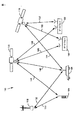
図8は、コード・ドップラー・タイミング・エラーと本発明のプロセッシングタイムとの関係を示すグラフである。プロセッシングタイムは各付加的な周波数仮説と共に増大するので、x軸は[周波数仮説の数]と記載され得る。総プロセッシングタイムはTs・[周波数仮説の数]である。点線は、コードドップラー推定が周波数ビンの中間に基いている場合に生じるタイミングエラーを表し、ただ一つのパイロット信号サンプルセットが処理される。実線は、コードドップラー推定が図4のffに基いている場合に生じるタイミングエラーを表し、二つのパイロット信号サンプルセットが並列に処理される。1つのサンプルセットは時間どおりであり、1つのサンプルセットは遅いであり、一実施の形態では遅いセットは時間どおりのサンプルセットより1/2チップ期間すなわち4クロックパルス遅れてサンプリングされる。
【0058】
図8を参照して、複数の周波数仮説( hypotheses)上でタイミング・エラーの大きさを最小にすることがゴールであることを思い出さなければならない。図8の時間通りのカーブと遅いカーブとは、縦並びにそれらの仮説を使用するは、中間ビン(bin)カーブで示すように、ビン仮説のまさに中間よりも低い大きさのタイミング・エラーを提供することを示している。これは、遅いカーブが中間ビンカーブより低いタイミング・エラーを提供する仮説faとfb'の間で容易に見られる。
【0059】
遅いカーブタイミングエラーがその最大の大きさに近づくfa未満でfbより大きい仮説に関して、時間通りのカーブは、その最小の大きさに近づく。時間通りの及び遅いサンプルセットが平行して処理されるので、特別の周波数仮説でそれらのうちのただ一つは、パイロット信号が工程315でうまく逆拡散されるために、低いタイミング・エラーの大きさを有する必要がある。
【0060】
概要において、本発明の一つの好適な実施例は、コードドップラーエラー(code Doppler error)効果を軽減するために二つの関連した、しかし明確な改良(refinements)を利用する。第1の改善は、図4周波数ビンのffに基づいてコードドップラー・エラー推定を計算することである。
【0061】
この推定は、複数の周波数仮説を処理する間に累算するタイミング・エラーを修正するために、PN-発生器を進めるかまたは遅くらせるために用いられる。第二の改良は、本願発明がまさに一つのサンプルセットの代わりに平行して二つのパイロット信号サンプルセットを処理することである。
【0062】
1つの好適な実施例において、遅いサンプルセットは、時間どおりのサンプルセットに比して二分の一チップだけ遅らされる。これは、図4の最後周波数(ff)に基づくコードドップラー推定と連動して、ただ一つのパイロット信号サンプルセットを処理するスキームに比する際、複数の周波数仮説上のより低い全体的なタイミングエラーの大きさとなる。
【0063】
上記の議論において、遅いサンプルセットは、時間通りのサンプルセットに比して1/2チップだけ遅れる。これは、1つの好適な実施例にすぎない。他の好適な実施例は、1/2チップ期間以外の1チップのいくつかの(some)分数だけセットされた遅いサンプルを遅延させることができる。
【0064】
上記の説明は、コードドップラー・エラーの効果を減少させるための一実施例にすぎない。別の実施例は、図4周波数ビンの中央でのコードドップラー推定に基づいており、平行して3つのパイロット信号サンプルセットを処理する。3つのサンプル・セットは、以下から成る: 時間どおりのサンプルセット、パイロット信号が時間通りのサンプルセットの前で1チップの分数をサンプルされるアーリー・サンプルセット、及び 前記パイロット信号が時間どおりのサンプルセットの後で1チップの分数をサンプルされる遅いサンプルセット。 もちろん、この実施例は、ただ2つのサンプルセットを処理するよりも多くのハードウェアを必要とし、それはある状況において、不利かもしれない。
【0065】
V.発明のブロック図:
図9は、本発明の1つの実施例を例示するブロック図である。
【0066】
本実施例において、システムは以下を含む: アナログ/ディジタル変換器903、コンプレックス・ロテータ( complex rotator)906、ダイレクト・デジタル・シンセサイザ909、プログラム可能な周波数累算器912、信号逆拡散器915、コヒーレント・コンプレックス累算器(coherent complex accumulator)918、エネルギー探知器921、エネルギー累算器924、エネルギー最大ー探知器927、コードドップラー訂正累算器933、システム・クロック936およびタイミング・ジェネレータ939。
【0067】
未知量のドップラーシフト(shift)を有するパイロット信号901は、サーチャー受信機218により検出されて、処理のために提供される。サーチャー受信機218は、パイロット信号901が図4に示めされるようなfi,ffにより境界される周波数ビンの範囲内であることを決定する。1つの実施例において、パイロット信号901は、同相の(I) 901aと直交の(Q)901b要素を有する複合のスペクトラム拡散信号である。
【0068】
パイロット信号901はアナログ受信機214によって、適当なRE送信バンドからダウンコンバートされた。しかし、その周波数スペクトルは未知の量のドップラーシフトの故に、DCを中心としない。
パイロット信号901は、アナログ-ディジタル(A/D)コンバータ903によって、デジタル化される。ここにおいて、ひとつの実施例において、サンプルは8倍のチップ・レート(8xチップまたは8×オーバーサンプリング)で形成される。(典型的に、当業者は拡散信号デジタル・ビットを「チップ(a chip)」と称する。PNジェネレータにより出力されるPN符号または複数の拡散ビットは、また「チップ(chips)」と称される。)。コンプレックス・ロテータ906は、それから現在の周波数仮説907によって、パイロット信号901の周波数スペクトルを変換する。変換されたパイロット信号910を生産するためにダイレクトディジタル・シンセサイザ(DDS)909により、現在の仮説は合成される(synthesized)。変換されたパイロット信号910はIとQの構成要素910a,bとの複合(complex)である。プログラム可能な周波数加算器912は、現在の周波数仮説値911をDUS 909に供給する。周波数加算器912は、テストされる複数の仮説上で現在の仮説値911を増加する。これは、最初の周波数912a、最後の周波数912bおよび仮説912cの数についてプログラムされた入力により決定される。最初の周波数と最後の周波数は、図4周波数ビンのfiとffに対応する。A/D後にパイロット信号のスペクトル901を変換するコンプレックス・ロテータ906の使用は、一つの実施例である。別の実施例は、周知のアナログミキシング技術を使用するA/D変換の前にパイロット信号901を変換する。
【0069】
拡散パイロット信号910は、適当なPNコードシーケンスにより信号910を、(例、多重化を介して、)結合することにより逆拡散器915中で逆拡散される。一つの実施例において、同相(I)パイロット信号要素901aは、拡散直交(Q)要素901bに使用されるそれから統計学的に独立している伝送の期間中にPNシーケンスで拡散される。この実施例は、同じ周波数チャネルを共有するが、別個のPN符号を有するユーザ・ターミナル間を分離する追加レベルを提供する。パイロット信号910を逆拡散するために、915逆拡散器は、伝送期間の間に要素を拡散するために使用された同一の各PNシーケンスにより、又はを用いてIとQ要素910a,を乗じるか、結合する。
【0070】
逆拡散器915の1つの好適な実施例において、パイロット信号IとQ要素910a,bは、8倍のチップレート(8xチップ)から2xチップ・レートに減じられ、各I910aとQ910Db要素に関する2セットのサンプルを産する。一つのサンプルセットは、「時間通り」とラベルされ、一つのサンプルセットは「遅い」とラベルされる。ここにおいて、遅いセットは、1/2チップをサンプルされ、或いは時間とおりのサンプルセットよりも4クロックパルス遅い。したがって、逆拡散器915は4つのサンプル・セットを産する、すなわち:時間通りのI要素916a、時間とおりのQ要素916b、遅いI要素917a、及び遅いQ要素917b。平行した2つのサンプルセットの処理は、ただ一つのサンプルセットの処理に比較される複数の周波数仮説上で、より小さいタイミング・エラーをもたらす。また、コードドップラー推定93aは、逆拡散器915PN発生器とパイロット信号910との間でのタイミング位相を周期的に調整するためにコードドップラー訂正累算器(CDCA)933によって、使われる。
【0071】
図10は、以下を含む逆拡散器915の1つの好適な実施例を例示する:4つに分割されたデシメータ(decimators)1003a,b、サンプラズ(samplers) 1006a.b,c,d、遅延要素1009a、b、同相のPN-ジェネレータ1012、直交PN発生器1015および乗算器lOl8a,b,c,d。パイロット信号IとQ要素910a,bは、4つに分割されたデシメータ1003a,bにより減じられ(decimated)、2xチップレートでIとQ信号1004a,bを産する。IとQ要素1004aはサンプラー1006a,bでサンプリングされ、1007a信号が「時間どおり」とラベルされ、1007b信号が「遅い」とラベルされる信号1007a,bを産する。ここにおいて、遅い信号1007bは、遅延要素1009aの後でサンプリングされる。一つの実施例において、遅延要素1009aは、遅いI要素1007bを時間通りI要素1007aに比して、1/2チップ期間又は4クロックパルスだけ遅延させる。I要素信号1007a,bは、同相PN発生器により発生されたPNシーケンス1013に乗算され、時間どおりの及び遅い同相の逆拡散信号916a、917aを産する。Q要素1004bは、サンプラ(samplers)100
6c,d、遅延要素1009b、そして直交PN-発生器 1015によって、同様に処理される。唯一の違いは、直交PN発生器1015により形成されたPNシーケンスが同相PN発生器1012により発生されたそれから統計的に独立していることである。したがって、逆拡散器915は4つのサンプル・セットを生産する、すなわち:時間通りのI要素916a、時間とおりのQ要素916b、遅いI要素917a、そして、遅いQ要素917b。
【0072】
時間通り(On-Time)のIとQ要素916a,bと遅いIとQ要素917a,bは、コンプレックス累算器918によりx−チップ上でコヒーレントに(coheren
tly)に累算され、時間通りのIとQ累算された要素919a,b及び遅いIとQ累算された要素920a,bを生産する。デジタル累算器は、当業者によって、周知である。一つの実施例において、コヒーレントな累算器は、256チップ上でなされるが、他の期間も使用されることができる。より長い累算期間は、より高い信号対雑音比を生ずるが、また、コードドップラー・エラー効果が立ち上がることができる。これらの効果は、次の周波数仮説処理において、逆拡散するPNシーケンスの効果を減少する。
【0073】
エネルギー検出器 921は、時間通り要素919a,bおよび遅い要素920a,bのエネルギーを測定する。時間どおりの信号エネルギーは、IとQ要素919a,bの二乗を加えることにより測定され、時間とおりのエネルギーサンプル922を産する。同様に、遅い信号エネルギーは、遅いIとQ要素920a,bの二乗を加えることにより測定され、遅いエネルギー・サンプル923を生する。エネルギー累算器924は、m倍のx−チップ(コヒーレントな累算回数m加算ごとのx―チップ)の期間上でmエネルギー測定を累算し、時間とおりのエネルギー累算値(EAV)925と遅いエネルギー累算値(EAV)926を産する。
【0074】
EAVs 925と926は、それからエネルギー最大検出器927に送られ、そこでそれらは複数の先行(foregoing)周波数仮説から最大限に格納されたEAY928bと比較される。最大限に格納されたEAV 928bが三つの中で最も大きいものである場合、それから、何も変わらず、周波数累算器912は直ちに周波数仮説値911を増加する(increments)。しかし、時間通り又は遅い EAVs 925、926のいずれかが最大限に格納されたEAV 928bより大きい場合、時間通り又は遅い EAVs 925、926の中でより大きいものは将来の周波数仮説比較のために最大限に格納されたBAY 928bを置換する。また、現在の周波数仮説値911は、前の優勢を得た周波数仮説を置換する優勢を得た周波数仮説928aとして格納される。優勢(wining)を得たEAVの時間通り/遅い状態の928cはまたノートされ(noted)、格納される。
【0075】
現在のEAV比較が終了したあと、プログラム可能な周波数累算器912は周波数仮説値911を増加し、該ループは新規な周波数仮説をもとめて繰り返される。ループはfiとffの間での複数の周波数仮説上で繰り返され、全ての仮説がテストされた後で格納される優勢を得た周波数仮説928aはドップラーシフトされたパイロット信号901の中心周波数に最も近い。優勢を得た周波数仮説928aとその時間通り/遅い状態の928bは、トラフィック・チャネル又はメッセージ信号のような、信号の復調に使用されるためのディジタルデータ受信機216A−Nに送られる。
【0076】
テストされる周波数仮説の数は、入力912cを介して周波数累算器912の最初のプログラミングにより制御される。明らかに、テストされる仮説が多いほど、より優勢を得た周波数仮説928aはパイロット信号の本当の中心周波数のより近くにある。しかし、コードドップラー・エラー効果のため、テストされる仮説の数とパイロット信号910を正確に逆拡散する能力との間にはトレードオフがある。一つの実施例において、周波数仮説の数は、本発明が23kHzから3kHzまでの周波数不確定(uncertainty )に狭めるように、選ばれる。
プログラム可能なコードドップラー訂正累算器(CDCA)933は、コードドップラー・エラーのために立ち上げられたPNシーケンス1013、1016とパイロット信号910サンプルとの間で累算されたタイミングエラーをモニターする。一つの実施例において、タイミング・エラーが大きさにおいて、1/8チップに達するときに、CDCA 933は累算されたタイミング・エラーを修正するためにタイミング・ジェネレータ936に「前進」または「遅れ」信号937を出す。
【0077】
図9、10および11は、CDCA 933により実行されるコードドップラー訂正の一実施例を示す。システム・クロック939は、図11で示すように、8xChipレートでクロック信号940を生成する。タイミング・ジェネレータ936は、クロック信号940を受信して、図iiに示すように、逆拡散器915に対して名目上1xチップレートで、イネーブル信号938a,bを供する8つに分割された回路(a divide-by-8 circuit)である。信号938aはサンプラ(samplers)1006a,b,c,dを使用可能にし、信号938bはPNジェネレータ1012、1015を使用可能にする。これは、マルチプライア1018a,b,c,dおよびPNジェネレータ1012と1015からのコード出力を使用して同相の信号1007a,bおよび直交信号l008a,bが逆拡散される結果となる。
【0078】
CDCA 933は、コードドップラー・エラー推定934に基づいて複数の周波数仮説上で累算されたタイミング・エラーを計算しモニターするプログラム可能な加算器である。累算されたタイミング・エラーが8分の1チップに達するときに、CDCA 933はタイミング・ジェネレータ936に「前進」(advance)または「遅れ」(retard)信号937を出す。「前進」/「遅れ」信号937は、タイミング・ジェネレータに、パイロット信号910a,bおよびPNシーケンス1013、1016間の累算されたタイミング・エラーを修正するために要求されることに依存して、名目よりも 8分の1チップ早い又は遅いPNジェネレータ・イネーブル信号938bを送らせる。上記のように、CDCA 933は、コードドップラー推定934に依存する前進/遅れ信号を出す。
【0079】
例えば、送信信号におけるチップレートが毎秒1.2288×10⁶チップのオーダーであるならば、そして40ppmのコードドップラー推定(エラー)があるならば、1秒間に累算されたドップラーエラーは(40/106)・毎秒1.2288x 106又は約49.152チップ/秒である。8×サンプリングが使われるときに、毎秒前進または遅れ増加/減少の数は、どのくらいの数の1/8チップが毎秒生起するかにより決定される。したがって、49.152チップ/秒の累算されたエラーは、393.216(1/8チップ)/秒であり、そして、訂正のため複数の周波数仮説のテストの期間に発せられる毎秒当たりのこの多くの前進又は遅れ信号を要求する。当業者は、非分数値の使用と同様に、与えられたチップレート及びサンプリング周波数に関して適切である前進および遅れ信号或いは増加/減少命令の数を決定する方法を理解する。
【0080】
VI.結論
好適な実施例に関する上記の説明は、いずれの当業者も本発明を作るかまたは使用することを可能にするために提供された。
【0081】
本発明が特にそれの好適な実施例に関して図示され説明されたので、当業者は形式および詳細に関して本発明の精神と範囲から逸脱することなく種種の変更がなされ得ることを理解する。
【図面の簡単な説明】
【図1】 本発明を用いることが有用な無線通信システムの一例を示す図である。
【図2】 ユーザ端末において用いられる発信機の一例を示す図である。
【図3】 発明の好適な実施形態に従って、検出されたパイロット信号の周波数不確定の範囲を狭める際の本発明の動作を示すフローチャートである。
【図4】 ドップラーシフトしたパイロット信号を含んでいることが分かっている、fiおよびffによって境界が定められた周波数ビンを示す図である。
【図5】 検出されたパイロット信号の周波数変換を示すフローチャートである。
【図6】 スペクトル拡散パイロット信号の逆拡散を示すフローチャートである。
【図7】 現周波数仮説のエネルギー累算値と、先行する周波数仮説からの最大エネルギー累算値との比較を示すフローチャートである。
【図8】 符号ドップラータイミングエラー対処理時間のプロット図である。このプロット図は本発明の2つの実施形態を示している。実線は、2つのパイロット信号サンプル組を処理し、符号ドップラーエラーの推定を図4の周波数ビンの最終周波数ffに基づいて行った好適な実施形態を示している。破線は、符号ドップラーの推定を図4の周波数ビンの中間周波数に基づいて行った1つのサンプル組を示している。
【図9】 本発明の好適な実施形態の実現例を示すブロック図である。
【図10】 図9に示す逆拡散器915の好適な実施形態の実現例を示すブロック図である。
【図11】 符号ドップラー訂正累算器933によって制御される時に、タイミング発生器936により送られたPN発生器イネーブル信号938bを示すタイミング図である。
【符号の説明】
112…基地局、116…衛星、124…ユーザ端末、140…線
[Document name] Statement
PROBLEM TO BE SOLVED: To narrow down a frequency uncertain range of a Doppler-shifted signal.
[Claims]
1. The frequency of the detected pilot signal is uncertain, including the following.ofRangeNarrowSystem for:
On multiple chips for each of multiple frequency hypothesesofA means for coherently accumulating samples of detected pilot signals,
A means for measuring energy with respect to the accumulated pilot signal sample,
To generate an energy cumulative value (EAV),Means for accumulating a plurality of the energy measurements, and
EAV with the highest of the multiple frequency hypothesesbecomeA means to determine.
2. The system of claim 1, wherein the means for determining the determination comprises:
Current frequency temporary, The largest EAV of the preceding frequency hypothesisWhenMeans of comparison, where the current frequency hypothesis EAV is greater than the maximum EAV, then
The maximum EAV is a plurality of EAVs generated by the future frequency hypothesis.
Replaced by the current frequency hypothesis EAV for comparison with, and
And
The current frequency hypothesis is storedas well asIt replaces the frequency hypothesis corresponding to the maximum EAV.
3. The detected pilot signal is a spectral diffusion signal and an appropriate PN sequence.soThe system of claim 1, further comprising means for despreading the pilot signal sample by multiplying the sample.
4. The PN sequence.soFurther provided are means for forming at least two sets of pilot signal samples before being multiplied, wherein at least one set of said samples is shifted in time compared to the other sets of said samples. The system of claim 3.
5. The PN sequence.soFurther provided by means for forming at least two sets of pilot signal samples before being multiplied, where one set of said samples is a set of samples on time and the other set of said samples is a slow sample set. The system of claim 3, wherein the slow sample set is shifted in time by a chip as compared to the on-time sample set.
6. According to the current frequency hypothesis,The system of claim 1, further comprising means for shifting the frequency of the detected pilot signal, wherein the current frequency hypothesis is one of the plurality of frequency hypotheses.
7. Further comprising means for increasing the current frequency hypothesis on the plurality of frequency hypotheses.RequestThe system of claim 6.
8. DetectionWas doneThe system of claim 6, further comprising means for converting the detected pilot signal from an analog signal to a digital signal before shifting the frequency of the pilot signal.
9. The means for shifting is a complex.RotatorThe system of claim 8.
10. After shifting the frequency of the detected pilot signal.,The system of claim 6, further comprising means for converting the detected pilot signal from an analog signal to a digital signal.
11. The system of claim 1, further comprising means for correcting a code Doppler timing error.
12. The system of claim 3, further comprising means for correcting a code Doppler timing error between the pilot signal sample and the PN sequence.
13. The system of claim 12, wherein the means for correction comprises means for adjusting the timing of the PN sequence as desired to correct a code dot puller timing error. ..
14. RevisedThe system of claim 12, wherein the means for correction comprises:
Accumulation of code dot plug timing errors between the pilot signal sample and the PN sequenceArithmeticMeans for monitoring,
Code Doppler-timing error if neededTo correctMeans for adjusting the timing of the PN sequence.
15. The means for monitoring is a code dot plug error.Estimated14. The system of claim 14.
16. The code dot plug error.EstimatedIs a known including the detected pilot signalFrequency binLast frequencyToThe system of claim 15 on which it is based.
17. The code dot plug errorEstimatedIs the system of claim 15, which is based on a frequency in a known frequency bin that includes a detected pilot signal.
18. The means for shifting is a complex.RotatorThe system of claim 7, wherein the direct digital synthesizer comprises and a direct digital synthesizer, wherein the direct digital synthesizer is controlled by a frequency calculator.
19. The frequency of the detected pilot signal is uncertain, comprising the following steps.ofRangeNarrowHow to:
(1) On multiple chips for each of multiple frequency hypothesesofCoherently accumulate samples of detected pilot signals,
(2) Measure the energy related to the accumulated pilot signal sample,
(3) Accumulate a plurality of the energy measurements in order to generate an energy cumulative value (EVA).
(4) Determine which of the multiple frequency hypotheses results in the highest EVA.
20. The method of claim 19, wherein step (4) further comprises:
The EAV on the current frequency hypothesis,Compare with the maximum EVA of the preceding frequency hypothesis, where the current hypothesis EVA is greater than the maximum EAV, then ...
a) Multiple EAVs generated by future frequency hypothesesWithComparisonofTo replace the largest EAV with the current frequency hypothesis EAV,
b) The circumference corresponding to the maximum EAV that stores the current frequency hypothesis.
Replace the wavenumber hypothesis.
21. The detected pilot signal is a spectral diffusion signal, and the pilot is multiplied by the sample according to a PN sequence.signalSumpLe19. The method of claim 19, further comprising a step of backdiffusion.
22 The step further comprises forming at least two sets of pilot signal samples before being multiplied by the PN sequence, wherein at least one set of the samples is compared to the other sets of the samples. 21. The method of claim 21, which is shifted in time.
23. Further comprises the step of forming at least two sets of pilot signal samples before being multiplied by the PN sequence, where one set of the samples is a sample set on time and the other of the samples. 21. The method of claim 21, wherein the set is a slow sample set, wherein the slow sample set is concealed in the on-time sample set and only the chips are shifted in time.
24. According to the current frequency hypothesis.,The method of claim 19, further comprising a step of shifting the frequency of the detected pilot signal, wherein the current frequency hypothesis is one of the plurality of frequency hypotheses.
25. The method of claim 24, further comprising a step of increasing the current frequency hypothesis on the plurality of frequency hypotheses.
26. The method of claim 24, further comprising the step of converting the detected pilot signal from an analog signal to a digital signal before shifting the frequency of the detected pilot signal.
27. After shifting the frequency of the detected pilot signal.,The process of converting the detected pilot signal from an analog signal to a digital signal.ToClaims24the method of.
28. The method of claim 19, further comprising a step of correcting a code dot plug timing error.
29. Code Doppler ...timing·21. The method of claim 21, further comprising a step of correcting an error.
30. Code Doppler ...timing·29. The method of claim 29, wherein the step of correcting the error comprises the step of adjusting the timing of the PN sequence when it is desired to correct the code dot plug error.
31. Code Doppler ...timing·The process of correcting an error is as follows.Process29.
(1) Code Doppler between the pilot signal sample and the PN sequence.timing·Monitor error accumulation and
(2) Code Dotsupura- ・timing·Adjust the timing of the PN sequence when it is necessary to correct the error.
32. The step of monitoring is a code dot plug error.EstimatedClaim 3 based on1the method of.
33. The code dot plug error.Estimated32. Is based on the last frequency of a known frequency bin that includes a detected pilot signal.
34. The code dot plug error.Estimated32. The method of claim 32, which is based on a frequency in a known frequency bin that includes a detected pilot signal.
Description: TECHNICAL FIELD [Detailed description of the invention]
[0001]
[Technical field to which the invention belongs]
The present inventiongeneralMore specifically, although it is unknown, there is a wireless communication system.LimitDoppler shift amountHave, Frequency uncertain of detected pilot signalofrange(the range of frequency uncertainty)ToNarrowRegarding the system.
0002.
[Conventional technology]
Various multiplex access communication systems and technologies have been developed to transmit information between a large number of system users... However, Code Division Multiple Access (CDMA) Spectral Spreading TechnologylikeSpectral diffusion modulation technology is another modulation scheme, especially when servicing a large number of communication system users.Important beyondProvide benefits. The use of CDMA technology in multiple access communication systems is defined by US Pat. No. 4,901,307, issued February 13, 1990, "Spread Spectrum Multiple Access Communication System Or Terrestrial Repeaters), and US Pat. No. 5,691,974, issued November 25, 1997, "Spread spectrum communication system for tracking individual receiver phases, time and energy." Methods and equipment for using the transmission power of the entire spectrum inDisclosed in.. Both of these patents have been assigned to the assignee of the invention and are incorporated herein by reference.
0003
These patents are numerous,generalMobile or remote, systemofThe user or subscriber unit (“user terminal”) is a pay phoneExchangeLike a network (public telephone switching network),Users of other connected systemsOr another user terminalTo communicate withofAt least oneTransceiverThe communication system to be used is disclosed. Communication signals are satellite repeaters and gatewaysOne ofThrough or directly, ground base stations (SometimesWith cell-sites or cellsAlsoTo be called)transferWill be done.
0004
Timing is crucial in modern satellite communication systems. For example, these systemsTypically, Communication channels, eachThe frame isKnown durationHaveMultipleofDivide into "frames". Benefits of these frames when transmitting signals or dataForFor optimization, gateways or base stations and user terminals must employ some method to ensure synchronization. Therefore, each user terminal is provided with a device for giving a timing reference. An ideal time reference gives a signal of a known frequency to the user terminal.
0005
On the user terminalLeaveLocal oscillators are often used to provide timing criteria. However, there is no perfect local oscillator. Local oscillator, frequencyDrift(Freequency drift)receive.. The frequency of the local oscillatorDriftThen the synchronization is lost.
0006
Local oscillator frequencyDriftOne approach to minimizing this is to manufacture a more accurate local oscillator. However, such a very stable local oscillator is very expensive to manufacture and can unacceptably increase the cost of the user terminal.
0007
Another widely used approach in cellular telephone systems is the voltage-controlled temperature-compensated crystal oscillator (VTCXO).Including.. The output frequency of the VTCXO can be controlled by changing the input voltage to the VTCXO. VTCXO is a frequency caused by temperature changesDriftVery strong against.
0008
In such a cellular telephone system, each user terminal is provided with a VTCXO. Each user terminal is from the base stationSendMonitor the pilot signal to be done. The user terminal adjusts the output frequency of the VTCXO by changing the applied input voltage by using the frequency of the pilot signal as a timing reference. In a cellular telephone system, such an approach can be used because the relative speed between the base station and the user terminal is small.
0009
However, in the case of some satellite communication systems such as the Low Earth Orbit (LEO) satellite communication system, the relative between the satellite and the user terminalradiationThe radial velocity can be very high. This big relativeradiationThe speed is determined by the LEO satelliteSendMake a big Doppler shift on the pilot signalForce.This makes the above techniques inaccurate and potentially unusable as timing criteria.Ru.. Satellite frequency ftAt the signalSendIf so, the received signal frequency frIsIt will look like this:
fr= Ft± fD (1)
fD= Ft・ [V / c] (2)
However, V = for the receiverSendMachine speed
c = speed of light in a suitable medium
fD= Doppler frequency shift
0010
Satellite is a user terminalWhoLine toKuIn this case, the period of the electromagnetic wave is shortened, and the [+] sign is used in the above equation. Satellite moves away from user terminalgoIn some cases, the electromagnetic wavesExtendAnd use [-]. The Doppler effect is expressed by the Doppler ratio [V / c].GainTo. However, V is for the receiverSendThe speed of the machine, where c is the speed of light in a suitable medium. The magnitude of the Doppler frequency shift is f compared to the Doppler ratio.tIs multiplied by.
0011
Doppler shift is especially noticeable in LEO satellite systems. For exampleTypicalThe speed of the LEO satellite can be 7 km / sec with respect to the user terminal. This results inSendIf the machine frequency is 2.5 GHz, one million minutes23 ofDoppler ratio of rate (or 23 ppm), and 58 kHz (or 58 kHz)Less thanIt becomes the Doppler frequency shift of (calculated by equation 2 of).
0012
Doppler frequency shift exists and digital data streamSendThenAlways, Code dopplererror(Code Doppler error) occurs. Code dopplererrorIsSendThe credit device is the receiverWhoToOrHanareMove toAs a result, the receiver bit rate fluctuates with respect to the transmitter bit rate. Code dopplererrorTo the Doppler ratio [V / c]TransmitterIt is multiplied by the bit rate. The resulting bit rate on the receiver side isSendCode Doppler to machine bitrateerrorIs added / subtracted. However,SendThe machine is the receiverWhoToMoveIf so, use the [+] sign.SendThe machine moves away from the receiverMove toIf so, use the [-] sign. This relationship isIt is expressed by the following formula.
rr= Rt± rD (3)
rD= Rt・ [V / c] (4)
However, rrIs the receiver bit rate
rtIsTransmitterbit rate
rDIs the code dopplererror,
V and c are the same as in equation 1 above...
0013
Code dopplererrorFor pseudo noise (PN) generator synchronizationAccumulationIt is particularly harmful in spectrum diffusion communication systems because it has a positive effect. In the case of a conventional spectral diffusion communication system, a set of preselected pseudonoise (PN) code sequences is used.Before modulating the carrier signalPredetermined spectral bandUpModulates (ie, "spreads") digital messages with. In order for the spectral diffusion receiver to correctly "despread" this signal, the chipping or chip rate of the local PN generator (the rate at which the chip is generated) is the received signal chip rate and time. Must be synchronized. ["Chip" issingleIt is an industry term that refers to the PN sign bit. Digital messages (voice, data, etc.) diffused using a PN code chip are also sometimes said to contain a "chip", but a "symbol"."Butpreferable. ] If the received signal chip rate is in units smaller than 1 Hz, the clockerrorOver timeAccumulationAnd then the PN sequenceToIncomingTo doBitstreamWithSyncToDemiseLet meIt will be. For example, an offset of 0.1Hz between the incoming chip rate and the local PN generatorIsAs a result, the timing of 0.1 chips per seconderrorAnd thisIsTiming for 6 chips per minuteerrorToAccumulateTo. That is, the received signalIs, Will be shifted by 6 chips from where it should be for proper backdiffusion by the appropriate PN sequence. Spectral diffusion to correctly despread a signalThe receiver isCode phaseDriftMust be less than half-chip cycle.errorIs greater than one chip,UselessinformationWill give birth to.. Therefore, the code Doppler in the spectral diffusion receivererrorIt is important to monitor and correct.
0014.
[Outline of the invention]
In the present invention, the frequency of the detected pilot signal is uncertain in a satellite communication system in which the pilot signal is unknown but has a bounded amount of Doppler shift.NarrowRegarding systems and methods. Pilot signal detectionperiodThe pilot signal is input to the frequency bin defined by the lower and upper frequencies. The present inventionIs, Multiple frequency provisional in this frequency binTheory(Frequency hypotheses) shifts the detected pilot signal, after which which hypothesis is the maximum energyAccumulationDetermine if it has a value. Maximum energyAccumulationHypothesis with valueBut, The hypothesis closest to the true center frequency of this pilot signalsois there. Typically,as a resultObtained frequencyDiscriminating power(Frequency discrimination)ofLevels are frequency hypotheses tested between lower and upper frequenciesofLimited only by number. However, if the pilot signal is a spectral diffusion signal, the hypothesis to be testedofNumber and energyAccumulationThere is a trade-off relationship with the accuracy of the value. In short, code DopplererrorCauses a loss of temporal synchronization between the spectral diffusion pilot signal and the pseudonoise (PN) code sequence used to despread the pilot signal. timingerrorIncreases with processing time (or the number of hypothesis values tested), and if uncorrected, subsequent frequency hypothesesToEnergyAccumulationIt will mislead the value.
0015.
The present invention is coded Doppler timing.errorTwo improvements have been incorporated to correct the problem. First, the code DopplererrorIs estimated based on the final frequency of the frequency bin known to contain the detected pilot signal. In the present invention, timing over a plurality of frequency hypotheseserrorofAccumulationMonitor and timingerrorHowever, it compensates for the loss of synchronization before reaching a level at which accurate backdiffusion of the pilot signal may not be possible. This correction is made by advancing or delaying the timing or chip rate of PN sequence generation relative to its nominal rate.
0016.
Code dopplererrorThe calculation of is based on the hypothesis that the pilot signal is located at the upper frequency of the frequency bin and is only an estimate. In reality, we do not know where the pilot signal is in the frequency bin. Therefore, the above correction is a plurality of frequency hypotheses.ToIt does not guarantee the amount of synchronization required to accurately despread the pilot signal over it. Code dopplererrorIn order to further reduce the influence of, in the present invention, each frequency hypothesisperiodIn addition, two sets of detectionWas doneReverse spread the pilot signal in parallel. One pilot signal set is described as "on-time", and one pilot signal set is described as "late". Delayed group is on timeofSampling is delayed by half a chip cycle with respect to the sample set. By back-spreading two sets of pilot signal samples in which one set is temporally shifted with respect to the other in parallel, the present invention presents a plurality of sets as compared to the case where only one set of samples is processed. Synchronization timing over the frequency hypothetical value oferrorIs reduced overall. This is because the slow sample set is in the center of the pilot signal frequency binThemhypothesisInMinimum timingerrorOn the other hand, the sample set is on time near the boundary of the frequency bin.ThemhypothesisToMinimum timingerrorBecause it becomes.
[0017]
By reading the following detailed description with reference to the drawings, the features, objectives and advantages of the present invention will become clearer. Throughout all drawings, similar reference numerals refer to the corresponding members.
[Disclosure of Invention]
I. Introduction
The present invention is particularly suitable for use in communication systems that use low earth orbit (LEO) satellites. However, as will be apparent to those skilled in the art, the concepts of the present invention can also be applied to satellite systems not used for communication purposes. The present invention can also be applied to satellite systems in which satellites navigate non-LEO orbits or non-satellite basic systems.
0018
Preferred embodiments of the present invention will be described below. Specific steps, forms and structures are described, but it should be understood that this is for illustration purposes only. Those skilled in the artIs, Other steps,Form, structureButOf the present inventionWith the purposeYou can recognize that it can be used without exceeding the range. The present invention includes a system with a goal in position fixing.VariousWireless informationWhenCommunications system,as well assatelliteas well asCan be used in terrestrial cellular telephone systems. A preferred application is a CDMA radio spread spectrum communication system for telephone services.
0019
II. Typical satellite communication system
The present invention is usefulIllustrativeAn example of a wireless communication system is shown in FIG. It is considered that this communication system uses a CDMA type communication signal. But according to the invention, it does not have to be. In a part of the communication system 100 shown in FIG. 1, one base station 112, two satellites 116 and 118, and two related gateways, that is, hubs 120 and 122, are used with two remote user terminals 124. Achieve communication with 126. Typically, base stations and satellites / gateways are on the ground.as well assatellitebaseIt is a component of a separate communication system called. But it doesn't have to be. The total number of base stations, gateways, and satellites in such a system depends on the desired capabilities of the system and other factors, as is well known in the art.
0020
User terminals 124 and 126 are cellular telephones, respectively.dataTransceiver,paging, Or a wireless communication device such as a position-fixing receiver. However, the wireless communication device is not limited to these illustrated. And, if necessary, the wireless receiver can be either handheld or vehicle-mounted. Here, the user terminals are illustrated as a handheld type 124 and a vehicle-mounted type 126, respectively. However, it is understood that the teaching content of the present invention can be applied to a fixed device or a device installed in a place where a remote wireless service is desired. The place mentioned here means not only "outdoor" but also "indoor".
0021.
In general, the beams from satellites 116 and 118 are partitioned in a predetermined pattern, different surface areas.Cover.. Different frequenciesBeam, Called a CDMA channel or "sub-beam",It is sent to the same area in an overlapping state. Multiple satellitesService area and beam coverage, orMultiple base stationsRegardingAntenna patternIsIt can be easily understood by those skilled in the art that it can be designed to overlap in whole or in part depending on the design specifications of the communication system, the type of service provided, and the achievement of spatial diversity.
0022.
A large number of user terminals using about 48 or more satellites navigating LEO orbits in eight different orbital planes.Various multi-satellite communication systems have been proposed.Further, those skilled in the art will understand that the teaching contents of the present invention can be applied to various satellite communication systems and gateway forms having other orbital distances and arrangements. At the same time, the present invention is similarly applicable to ground-based systems in various base station forms.
[0023]
In FIG. 1, communication between user terminals 124 and 126 and base station 112, or satellites 116 and 118.AssistanceSome signal passages for enabling such communication are shown together with gateways 120 and 122. Base station-user endSuedoriThe communication links are shown by lines 130 and 132. Satellite-end between satellites 116, 118 and user terminals 124, 126SuedoriThe communication links are shown by lines 140 and 142, 144. Gateways 120, 122 and satellites116, 118Gateway-to-satellite communication links to and from are indicated by lines 146, 148, 150, 152. Gateways 120, 122 and base station 112 are part of a unidirectional or bidirectional communication system, or simply a message ordataMay be used to transmit to user terminals 124 and 126.
0024
User terminal106One Trans Sheba 200 for use within is illustrated in FIG. The transsaver 200 has at least one antenna 210 for receiving a communication signal. The signal received by the antenna 210 is sent to the analog receiver 214, down-converted, amplified and digitized. A duplexer element 212 is typically used so that the same antenna performs both transmit and receive functions. However, some systems use separate antennas that operate at different transmit and receive frequencies.
0025
The digital communication signal output by the analog receiver 214 is at least one digital.dataIt is sent to receiver 216A and at least one search receiver 218. apparatusofComplexity(complexity)Digital, depending on the permissible level ofdataIt is possible to obtain a desired level of signal diversity by additionally using receivers 216B to 216N. It is obvious to those skilled in the art.
0026
The control processor 220 of at least one user terminal is coupled to the digital data receivers 216A-216N and the search receiver 218. The control processor 220 has various functions such as signal processing, timing, power, and handoff.ofBasic control and coordination, selection of frequencies used for signal carrierofProvide functionality. Another basic control function often performed by the control processor 220 is the selection and manipulation of pseudo-random noise (PN) code sequences and orthogonal functions used in the processing of communication signal waveforms. Signal processing by the control processor 220 can include determining relative signal strength and calculating various related signal parameters. Of signal parameters such as timing and frequencylike thatFor the calculation, a dedicated circuit added separately may be used in order to improve the efficiency and speed of measurement and the allocation of control processing resources.
[0027]
The outputs of the digital data receivers 216A to 216N are connected to the digital baseband circuit 222 in the user terminal...The user digital baseband circuit 222 includes elements for processing and presentation for exchanging information with the user of the user terminal. That is, signal and data storage elements, such as digital memory for temporary storage and long-term storage, input / output devices, such as display screens, speakers, keyboards, handsets, A / D elements, vocabularies, and other audio signals and analogs. All of the elements that process the signal and the like constitute the components of the user digital baseband circuit 222 using elements that are well known in the art. If diversity signal processing is adopted, a diversity combiner and a decoder may be incorporated in the user digital baseband circuit 222. Some of these elements operate in communication with the control processor 220. That is, it operates under the control of the control processor 220.
[0028]
Occurs from the user terminalRudeWhen data such as voice is prepared as a power message or communication signal, the user digital baseband circuit 222 is used for receiving, storing, processing, and other preparations of data desirable for transmission. The user digital baseband circuit 222 supplies this data to the transmit modulator 226 operating under the control of the control processor 220. The output of the transmission modulator 226 is transmitted to the power controller 228. The power controller 228 supplies output power control to the transmit power amplifier 230. The transmit power amplifier 230 upconverts and amplifies the baseband signal for final transmission from the antenna 210.
[0029]
The user terminal 200 adjusts the frequency of the transmission signal by using the pre-correction element 234 in the transmission path. This can be done using well-known transmit waveform up-conversion or down-conversion techniques. Alternatively, frequency selection for analog up-conversion and modulation stages performed within the transmit power amplifier 230.OrcontrolofA part of the mechanism may be composed of the pre-correction element 234.
[0030]
Various techniques known in this art are used for the received communication signal.One or moreInformation and data corresponding to the measurement signal parameters,Or,One or moreA shared resource signal may be sent to the gateway. For example, the information can be transmitted as separate information or added to another message prepared by the user digital baseband circuit 222. Alternatively, under the control of the control processor 220, the transmit modulator 226 orSendInformation can also be inserted as predetermined control bits by the power controller 228.
0031
DigitalReceivingThe transmitters 216A to 216N are configured to demodulate and track a specific signal together with a signal correlation element. Pilot signal and other relatively fixed using search receiver 218RupatternStrongSearch for traffic lights. On the other hand, demodulation of other signals related to the detected pilot signal is performed using the digital data receivers 216A to 216N. However, to determine the strength of the signalToData receiver 216After being acquiredIt may be assigned to track the pilot signal to accurately determine the ratio of signal chip energy to signal noise. Therefore, the output of these units can be monitored to determine the energy and frequency of signals such as pilot signals. The receiver 216 uses a frequency tracking element that can be monitored for the demodulated signal and the current frequency.as well asThe timing information may be supplied to the control processor 220.
[0032]
The pilot channel is simply a signal that is not modulated by the data and can take advantage of repeating invariant patterns and invariant frame-structured inputs (patterns). That is, the orthogonal function used to form the channel of the pilot signal is the Walsh code here, but generally all have a constant value such as 1 or 0, or 1 and 0 are. It has known repeating patterns such as scattered structured patterns. As a result, only the PN spreading code applied from the PN code generator can be efficiently transmitted. In addition, the pilot signal is powerless controlled. That is, the pilot signal isTypicallyAccurate measurement of signal power by the user terminal is achieved because it does not change because it is transmitted at a preselected fixed power level.
0033
The control processor 220 is appropriately adjusted for the same frequency band.(scale)At that time, such information is used to determine how much the received signal deviates from the oscillator frequency. Of frequency as described belowerrorAnd related to Doppler shiftotherInformation may be stored in a storage device or a memory element 236 as desired.
0034
III. Detailed description of the invention:
Figure 3 is fine(fine)It is operation flow diagram explaining the operation of this invention in frequency search (search). The present invention has been described within the environment of a spread spectrum satellite cellular communication system.ThisThe satellite is in low earth orbit <LEO> with respect to the user terminal and has a high radiation velocity. However, these techniques will recognize how this approach can also be applied to signals transferred by base stations without the use of satellites. That is, there is sufficient signal source / receiver movement here to generate the relevant Doppler frequency shift. For example, when using other types of mobile repeaters or fast-moving vehicles such as high-speed trains.
0035.
In step 303, the detected spread spectrum pilot signal is presented for processing by the searcher receiver 218. The pilot signal is down-converted from the radio frequency (RF) band received by the analog receiver 214 to the A / D-converted baseband. If the incoming signal frequency matches the receiver center frequency, then the signal carrier frequency is converted to direct current in the baseband. This is said to be concentrated around the direct current. However, it has low earth orbit (LEO) satellite communications (or rapidly changing separation distances).Source/ User terminalConstitutionThe Doppler frequency shift inherent in) shifts the incoming signal from the receiver central band. The resulting baseband signalFrequency spectrum ofIs not concentrated on or near direct current (OHz) due to the Doppler frequency shift, but has a positive or negative frequency shift. A code Doppler error is always associated with a Doppler frequency shift.
0036
During detection, the searcher receiver 218 will check if the pilot signal is within a preselected frequency range.Decide, This is generally shown in FIG.1And ffCalled a frequency bin..F in FIG.maxIs the frequency of the maximum Doppler shift that can occur when the system parameters are in their most extreme state. That is, f1And ffThe frequency bin defined by is -FmaxAnd + FmaxYou can slide between. The searcher receiver 218 is a frequency bin.BoundaryOr determine where the search range is located, and the present invention has a frequency hypothesis,Determines that it is closest to the center frequency of the detected pilot signal. Note that FIG. 4 shows the detected pilot signal as discrete tones for illustration purposes only. In fact, the 3 dB bandwidth of a typical spread spectrum signal can be 500 kHz wide, which complicates the task of determining the center frequency (task).
0037
In step 306, the code Doppler error is the f in FIG.fOn the basis ofEstimatedWill be done. thisEstimatedIsPeriodicallyThe timing of the PN generator in step 312 will be adjusted periodically. This PN generatorIsPilot signalUsed to backdiffuse.. In step 309, the frequency spectrum of the pilot signalthe currentBy the frequency hypothesis ofconversionWill be done. The frequency hypothesis is the discrete frequencies within the frequency bin of FIG. The term "hypothesis" is used because it is not known that one frequency in FIG. 4 is closest to the center frequency of the pilot signal until all frequencies in FIG. 4 have been processed.the currentThe value of the frequency hypothesis of is supplied in step 327. In one embodiment, the first frequency hypothesis is the lower frequency f in FIG.1And the frequency hypothesis isf i From high frequenciesf i Will be increased to. In an alternative example, the first hypothesis is ffAnd reduce each hypothesis.
[0038]
In another alternative embodiment, the bisector method is applied, in which fi, F f The entire frequency range between is first bisected and each half is tested for pilot energy. The winning half is then split in half again, and the process is repeated. In this implementation, the number of parts and the number of bins are 16 or more.When saying the order of, Faster than continuous search, but a bit more complicated to perform.
[0039]
conversionThe resulting pilot signal is then multiplied by a unique PN sequence on the pilot signal in step 312.Reverse diffusionIs done. In step 315Back-diffusedSignal sample is more than x number of chipsCoherentTo(coherently) AccumulationBe done..In step 318, the energyAccumulationMeasured for the signal sample. In step 321 the energy measurement is more than x chipsAccumulationAnd these cohesiveAccumulation"M" isthe currentEnergy for the frequency hypothesis ofAccumulationCreate value (EAV)Used to.. Therefore, EAV is composed of x times the m-chip of data.
0040
The basic trade-off at selected x is that larger values are most effective in collecting energy to make a good decision as to whether the hypothesis is correct, but the size of x. And the frequency being testedRangeIs inversely proportional to the width of. That is, the larger the value of X, the larger,testRange orFrequency bin widthIsIt becomes smaller. To avoid having very narrow bins and requiring a large number of hypotheses for testing, x is selected or adjusted to a reasonable size. A value of x equal to 256 for the exemplary system being discussed provides the desired approximate frequency bandwidth for the subintervals being tested, in this case about 3 kHz. If the value of x doubles to 512, the test can only "see" the pilot at 1.5 kHz intervals, and many hypotheses double the overall frequency.rangeWill have to be tested to cover.
[0041]
The greater the value used as m, the moreAccumulationMore energy is done, and each hypothesis is better testedBe doneCan be The size of m, if too large, takes too long to test the hypothesis and is near the end of the testsoThe common Doppler error is limited by the fact that it will be overkill. A preferred value of m is 27 in the above discussed exemplary system, which is an excessive Doppler error.AccumulationInvite or excessiveInvite accumulationIt tends to be about the same size as previously desired. Therefore, in one embodiment,AccumulationThe number of chips x was set to 256 and was used to generate EAV.AccumulationThe number of is set to 27.
[0042]
In step 324the currentThe EAV for the frequency hypothesis of is the stored maximum created by the previous frequency hypothesis.Large ECompared to AV. ifStoredIf the maximum EAV is greater, then nothing changes, and the ingenious process proceeds to step 327, where the frequency hypothesis is increased. But ifCurrentIf the frequency hypothesis EAV is greater than the previous maximum EAV, then to compare with the EAV created by the future frequency hypothesisthe currentThe frequency hypothesis EAV of is replacing the previous maximum EAV. The initially stored maximum EAV value automatically increases any next measurement used for comparison and becomes the stored value for testing the next hypothesis.likeTo be zeroChoice, Or is selected to be set to zero.
[0043]
In step 327, the frequency hypothesis is incremented, and steps 309-324 are repeated for the new frequency hypothesis. The loop is manipulated for each of the multiple frequency hypotheses, where the frequency hypothesis with the highest EAV is closest to the true center frequency of the detected signal.
[0044]
In general, the resulting level of frequency identification is f i ,ffLimited only by the number of frequency hypotheses tested during. However, when the pilot signal is a spread spectrum signal, the number and energy of hypotheses tested.AccumulationThere is a tradeoff with the accuracy of the value. In essence, a code Doppler error is a spread spectrum pilot signal and a pilot signal sample.BackdiffuseCauses a loss of time synchronization with the pseudo-noise (PN) code sequence used for. Timing errors are processing time (hence,The energy for these frequency hypotheses in the second half of the frequency bin in FIG. 4) increases with (the number of hypotheses tested) and, if not modified,AccumulationIt will make the value wrong. In one example, the number of hypotheses is the number of detected pilot signals.frequencyUncertainReal (Uncertainty) is chosen to be reduced from 23 kHz to 3 kHz.
0045
FIG. 5 is an operation flow diagram illustrating an embodiment for carrying out the present invention in step 309. In step 503, the detected pilot signal is received after processing from step 306. In step 506, the detected pilot signal is the chip rate.of8 times (8 x chip)soIt is digitized by analog-digital conversion to make a signal sample.the currentThe frequency hypothetical waveform of is synthesized in step 509 based on the input from step 327.(synthesize).. In step 512, the signal sample is of the pilot signal frequency spectrum.conversionAs a result inthe currentIt is rotated by the frequency hypothetical waveform of.The converted pilot signal is then narrowed down in step 306.
[0046]
conversionThe closer the frequency spectrum of the pilot signal is to direct current, the closerReversediffusionofThe operation compresses the diffusion pilot signal more effectively, which will eventually create a relatively large energy storage in step 321. FIG. 5 is only one embodiment of step 309. An alternative example is the well-known analog mixing.(mixing)Pilot signal prior to analog-to-digital conversion by technologyconversionTo do.
[0047]
Received signal is F1Focus on(centered)To test the hypothesis, this signal is a negative F1ByconversionBe (thisconversionIs RF / IFAnd multiple combineddigitalRotator conversion(Rotator translation)Made in), And then see if the energy is detected by direct currentTotest. Digital to test the negative Doppler hypothesisRotatorHas a positive frequency offset to give the baseband signalconversionUsed to do. If the Doppler shift is negative, the positive offset concentrates the baseband signal on DC.(centers), And good energy measurementOfferTo do. If the Doppler shift is not negative, the positive offset directs the baseband signal.ToDon't concentrate, focus on itFrom thatMove further,Poor energy measurementWill result in.. In a similar way, the positive Doppler hypothesis, To try to concentrate the baseband signal,Baseband signal with negative frequency offsetconversionDigital toRotatorTested by using (rotator). Therefore, the circuit that measures energy isAs is commonly done with direct current using rotators, the rotator shifts different parts of the incoming signal spectrum to direct current for these measurements.
0048
In FIG. 6, the pilot signal isBack-diffusedIt is operation flow diagram which illustrates one Embodiment of step 312. In step 603,conversionTranslatedThe signal sample is received from step 309. As described with reference to FIG. 5, in one embodiment, the pilot signal is multiplied by 8 during the A / D conversion period.ofIt is sampled at a chip rate (8 x chips), but other rates can be used for other applications within the teachings of the present invention, as will be appreciated by those skilled in the art. In step 606, the samples are halved to make two sets of samples at a 2x chip rate. For the sake of explanation, one set is “on time”(On-Time)The other set is "slow"(Late)"Slow samples are on timeofFrom the sample setAlso1/2 chipOrIt is created by sampling the pilot signal with a delay of four clock pulses. The slow sample set is f in the frequency bin of FIG.f, Last frequencyhypothesisCode Doppler in (hypothesis)EstimatedOccurs to gain the benefits of decisions based on. As will be explained later, this results in only one sample set being processed and a code Doppler error.EstimatedCompared to what occurred when (estimate) was based in the middle of the frequency bins in FIG.MultipleFrequencyhypothesisCode Doppler timing errors are low over time.
[0049]
In step 609, the present invention is a pilot signal.PN sequence and multiple signalsBetween samplesAccumulatedCode Doppler Timing ErrorToMonitor. In step 612, the PN sequence is advanced or delayed as necessary to correct the code Doppler timing error. In one embodiment, the timing of the PN sequence is advanced or delayed in 1/8 chip increments, and the timing of the advance or delay is a code Doppler error.EstimatedIs based on. In step 615, on timeofSample is composite(complex)In-phase (I) and on-time pilot signal in-phase (I) multiplexed by PN sequenceOrthogonal(Q)Back-diffusedGenerate a sample. In step 618, the slow sample is multiplexed with a composite PN sequence and the slow pilot signals I and QBack-diffusedGenerate a sample. In step 621, on timeofI and Q samples and lateIThe I and Q samples are on x chips above in step 315.Cross overAccumulated to coherent.
0050
FIG. 7 is an operation flow diagram illustrating one embodiment of step 324.the currentFrequencyhypothesisEnergy cumulative value for (EAV)s)ButMany previous frequencieshypothesisFromStoredMostLarge ECompared to AV. In step 703the currentFrequencyhypothesisOn time and slow sample setEAVs fromToFrom step 321receive. In step 706, on-time and slow EAVsIs a large number of previous frequencieshypothesisFromStoredMostBigCompared to EAV. MostBigIf the EAV is the largest of the three, processing proceeds to step 715. But on-time or slow EAVStoredMostBigIf it is larger than EAV,The method orThe process proceeds to steps 709 and 712. In step 709, EAV on time or latesThe larger one,FuturefrequencyIn the hypothesisFor comparisonStoredMostBigIt can be replaced with EAV. In step 712CurrentThe frequency hypothesis value and its on-time / slow state are memorized, and the immediately preceding dominant frequencyReplace the hypothesis). In step 715, the frequency immediately beforehypothesisIs the last frequency in the frequency bin of FIG.hypothesisA decision is made as to whether or not. If the answer is no, Creative (Vivado) processing returns to step 327 and the frequencyhypothesisThe value is increased and steps 309-324 are repeated. If the answer is yesCurrently storedPredominant frequencyhypothesisIs detected as shown in step 718Be doneClosest to the center frequency of the pilot signalhypothesisIs. Dominant frequencyhypothesisas well asSoOn time / slow state is demodulating the message following the pilot signalToused.
0051
IV. Code Doppler error correction
In one preferred embodiment, the present invention has two associations to correct code Doppler errors.ImprovementTo execute. First, f in the frequency bin of FIG. f Code Doppler error based on last frequencyEstimatedTo do. thisEstimatedIs used to adjust the timing of the PN generator to correct any accumulated timing errors. SecondTechnologyIn steps 312-324twoIt is to process the pilot signal sample of the set. One set of samples is described as "on time" and the other set is described as "slow", in one preferred embodiment.,Slow sample sets lag behind samples on time,When using 8x sampling, the pilot signal is given a 1/2 chip period or 4 clock pulses.ToGenerated by sampling. theseImprovementWill be described in detail below.
[0052]
A. Code doppler errorEstimatedAnd timing adjustment of PN generator
Frequency Doppler exists and digital data bit stream is transmittedingIn caseis always, Code Doppler error occurs. In one application described earlier, a speed close to 7 km / sec between the transmitter and the receiver has a Doppler ratio of 23 copies (ie 23 ppm) per million and a transmission frequency of 2.5 GHz.RegardingA 58 kHz Doppler frequency shift will occur. If the transmitter data rate is 1.0 Mbps, the code Doppler error is 23 bps. That is, the reception bit rate is 23 bps faster than the transmission bit rate. ValidBack diffusionFor detectionSaSignals and signalsBack diffusionUsed toBe doneThe chip error with the PN sequence is preferably 1/2 or less. Therefore, in this example, the receiver PN generator should be set to a clock rate 23 bps faster than the transmitter chip rate.
[0053]
In the above description, a code Doppler error simply increases the clock rate of the PN generator by 23 bps relative to the transmitter bit rate.onlyWas easily corrected by. It is based on a Doppler ratio of 23 ppm, which is calculated from a known Doppler frequency shift of 58 kHz. However, in the present invention, the amount of Doppler frequency shift is unknown. In fact, an object of the present invention is to detect at the boundary of the Doppler frequency shift and in an unknown quantity.Be doneIt is to find the center frequency of the pilot signal. Thus, in one embodiment, the code Doppler error will signal the pilot signal in step 312 of the present invention.Back diffusionTo adjust the clock rate of the PN generator used toEstimatedWill be done.
0054
Code Doppler errorEstimatedIs calculated from the equations (1) to (4) which are repeated here for convenience.
fr= Ft± fD (1)
fD= Ft・ [V / c] (2)
rr= Rt± rD (3)
rD= Rt・ [V / c] (4)
Where V is the speed of the transmitter relative to the receiver and c is the speed of light in a suitable medium.
0055
As I mentioned before,Determined the pilot signalSearcher receiver 218IsAs shown in FIG. 4, fiAnd ffIt is in the frequency bin bounded by. Simply cord dopplerEstimatedPurposeRegarding, The present invention receivesdidThe pilot signal is ffAndhypothesisTo do. thishypothesisAnd when equations 1 and 2 are used, the transmitter frequency (f)t) Is known, so the Doppler ratio [V / c] can be calculated. From the Doppler ratiocodeDoppler error (rD) Is the transmitter chip rate (r)t) Is known,It can be calculated using equation (4).r t Pilot signal chip rate (r) which is the same asp) Is the known transmitter chip rate (r)t) Using the relation of equation (3)EstimatedYes, "+" is frIs f t 'Used when greater than, "-" is frIs ftUsed when smaller. Pilot signal chip rate (rp)ofUsing estimationIn one embodiment of the invention, step 609 keeps track of cumulative timing errors between the PN sequence and the pilot signal sample, where the PN sequence is at the transmitter chip rate.ofNominally generated. When the timing error reaches 1/8 of the chip, the present invention corrects the accumulated timing error by advancing or delaying the timing of the PN generator as shown in step 612 of FIG.
0056
B. On-time and slow sample set
Code Doppler error, as mentioned aboveEstimatedIs the frequency bin f in FIG.fIs based on. This is a cord dopplerEstimatedDoppler error, assuming you want the best opportunity to minimize the difference between the frequency and the unknown actual pilot signal frequencyEstimatedSince the clearest frequency based on is in the middle of the frequency bin in Figure 4.,It's counterintuitive. However, ffCode Doppler based onEstimatedAnd by processing two sample sets in parallel, a large number of frequencies compared to what is achieved with a single sample sethypothesisTiming error is low..A aboveTermThe basis of the code Doppler timing correction mentioned in is the code Doppler error.EstimatedIs. thisEstimatedIs ff'Since it is based on the pilot signal in, the pilot signal is ff'Unless it is centered on,Timing error is between the pilot signal and the PN generatorsoAccumulate. This timing error is best represented in the relational expression
[0057]
[Number 1]
here,
ferr(X) = [Actual pilot signal chip rate]-[PN generator chip
Rate] (6)
Ts= 1 frequencyhypothesisTime to process(7)
= [# of step 315 accumulation], [# of step 321 accumulation], Tc ,
Tc= Chip duration (8)
FIG. 8 is a graph showing the relationship between the code Doppler timing error and the processing time of the present invention. Processing time is each additional frequencyhypothesisAs it increases with, the x-axis is [Frequency]hypothesisNumber]. Total processing time is Ts·[frequencyhypothesisNumber of]. Dotted line is code DopplerEstimatedRepresents a timing error that occurs when is based in the middle of the frequency bin, and only one pilot signal sample set is processed. The solid line is the cord DopplerEstimatedIs f in FIG.fRepresents a timing error that occurs when based on, and two pilot signal sample sets are processed in parallel.OneSample set is on time,OneThe sample set is slow, and in one embodiment the slow set is on timeofSampling is performed 1/2 chip period, that is, 4 clock pulses later than the sample set.
0058.
With reference to Figure 8, it should be remembered that the goal is to minimize the magnitude of timing errors on multiple hypotheses. Timely curve and slow in Figure 8ICurves are vertical and use those hypothesesIs, More than exactly in the middle of the bin hypothesis, as shown by the middle bin curveLow sizeTiming errorI will provide aIt is shown that. This is lateIThe curve is from the middle bin curveLowHypothesis f that provides timing errorsaAnd fb'Easily seen between.
[0059]
LateICurve timing error approaches its maximum magnitude faLess than fb bFor larger hypotheses, the on-time curve is the bestSmallGet closer to size. On time and lateISince the sample sets are processed in parallel, only one of them in the special frequency hypothesis is because the pilot signal is successfully backdiffused in step 315.LowTiming errorSize ofMust have.
[0060]
In summary, one preferred embodiment of the invention is two related, but clear, to mitigate the code Doppler error effect.ImprovementUse (refinements). The first improvement is the f in the frequency bin in Figure 4.fCode Doppler error based onEstimatedIs to calculate.
[0061]
thisEstimatedIs used to advance or slow down the PN-generator to correct timing errors that accumulate while processing multiple frequency hypotheses. SecondImprovementIs a sample set in which the present invention is exactly oneIn parallel instead ofProcessing two pilot signal sample sets.
[0062]
In one preferred embodiment, slowISample setIs, Delayed by half a chip compared to the on-time sample set.this is,Figure 4ofLast frequency (ff) Based on code DopplerEstimatedCompared to a scheme that processes only one pilot signal sample set in conjunction with, multiple frequency hypothetical sourcesLowOverall timing errorSize ofWill be.
[0063]
In the above discussion, lateIThe sample set lags the on-time sample set by 1/2 chip. This is just one preferred embodiment. Other suitable examples are other than the 1/2 chip period.1 chipSeveral(some)Slow set by a fractionIThe sample can be delayed.
[0064]
The above description is only one embodiment to reduce the effect of the code Doppler error. Another example is the cord Doppler in the center of the frequency bin in Figure 4.EstimatedBased on and parallelhandProcess three pilot signal sample sets. The three sample sets consist of: a sample set on time, an early sample set in which the pilot signal is sampled a fraction of one chip in front of the sample set on time, and a sample in which the pilot signal is on time. Slow sampled fractions of one chip after setISample set. Of course, this example requires more hardware than just processing two sample sets, which may be a disadvantage in some situations.
[0065]
V. Invention block diagram:
FIG. 9 is a block diagram illustrating one embodiment of the present invention.
[0066]
In this embodiment, the system includes: analog-to-digital converter 903, complex.Rotator(complex rotator) 906, direct digital synthesizer 909, programmable frequenciesAccumulationInstrument 912, signal despreader 915, coherent complexAccumulationCoherent complex accumulator 918, energy detector 921, energyAccumulationInstrument 924, Energy Max-Detector 927, Code Doppler correctionAccumulator933, system clock 936 and timing generator 939.
[0067]
The pilot signal 901 with an unknown amount of Doppler shift is detected by the searcher receiver 218 and provided for processing. The searcher receiver 218 determines that the pilot signal 901 is within the frequency bin bounded by fi, ff as shown in FIG. In one embodiment, the pilot signal 901 is a composite spread spectrum signal having a homeomorphic (I) 901a and an orthogonal (Q) 901b element.
[0068]
The pilot signal 901 was down-converted from the appropriate RE transmission band by the analog receiver 214. However, its frequency spectrum is not DC centered due to an unknown amount of Doppler shift.
The pilot signal 901 is digitized by an analog-to-digital (A / D) converter 903. Here, in one embodiment, the sample is formed at 8x chip rate (8x chip or 8x oversampling). (Typically, those skilled in the art refer to the spread signal digital bit as an "a chip", which is the PN code or output from the PN generator.pluralThe diffusion bit is also a "chip"(chips)Is called. )..complex·RotatorThe 906 then uses the current frequency hypothesis 907 to obtain the frequency spectrum of the pilot signal 901.conversionTo do.conversionThe current hypothesis is synthesized by a direct digital synthesizer (DDS) 909 to produce the pilot signal 910.conversionThe resulting pilot signal 910 is a complex of I and Q components 910a and b. The programmable frequency adder 912 supplies the current frequency hypothesis value 911 to the DUS 909. The frequency adder 912 is the current hypothesis value 911 on multiple hypotheses tested.ToTo increase. This is the first frequency 912a, the last frequency 912b and the hypothesis912cAbout the number ofDetermined by programmed input. The first and last frequencies are shown in Figure 4, frequency bin f.iAnd ffCorresponds to. After A / D, the spectrum 901 of the pilot signalconversionComplex to doRotatorThe use of 906 is one embodimentIs.. Another embodiment uses a well-known analog mixing technique to send the pilot signal 901 prior to A / D conversion.conversionTo do.
[0069]
The diffusion pilot signal 910 is provided by an appropriate PN code sequence.Signal 910 (eg,MultiplexingThrough)By combining in the back diffuser 915soIt is back-diffused. In one embodiment, common mode (I) pilot communicationissueElement 901a is a PN sequence used for diffusion orthogonal (Q) element 901b during a period of transmission that is statistically independent from it.sodiffusionBe done.. This example shares the same frequency channel, butSeparate PProvides an additional level of separation between user terminals with an N sign. To despread the pilot signal 910, the 915 despreader is the same each used to spread the element during the transmission period.PMultiply or combine I and Q element 910a, by or with the N sequence.
[0070]
In one preferred embodiment of the reverse diffuser 915, with the pilot signal IQ requiredElementary 910a and b have 8 times the chip rate (8x chip) to 2x chip rate.ToDecreaseJiraIt produces two sets of samples for each I910a and Q910Db element. One sample set is labeled "on time" and one sample set is "slow"IIs labeled. Here, lateIThe set is sampled with 1/2 tip, or on timeof4 clock pulses slower than the sample set. Therefore,Reverse diffuser 915 produces four sample sets, That is: On timeIElement 916a, on timeQElement 916b, slowI IElement 917a, and slowQElement 917b. Processing two parallel sample sets becomes processing of only one sample setTo be comparedIt results in smaller timing errors on multiple frequency hypotheses. Also, cord DopplerEstimated93a is the timing between the reverse diffuser 915PN generator and the pilot signal 910.phaseCode Doppler correction to adjust periodicallyAccumulationUsed by vessel (CDCA) 933.
[0071]
FIG. 10 illustrates one preferred embodiment of the backdiffuser 915 including: decimeter divided into four:(decimators)1003a, b, sampler(Samplers) 1006a.b, c, d, delay elements 1009a, b, common mode PN-generator 1012, orthogonal PN generator 1015 and multiplier lOl8a, b, c, d..The pilot signals I and Q elements 910a and b are divided into four decimeters 1003a and b.Decimated, I and Q signals at 2x chip rate1004a, bTo give birth to. With IQElement 1004aSampled with samplers 1006a, b, 1007a signal is labeled "on time" and 1007b signal is labeled "slow" to produce signals 1007a, b. Here, the slow signal 1007b is sampled after the delay element 1009a. In one embodiment, the delay element 1009a is the slow I element 1007.b bIs delayed by a 1/2 chip period or 4 clock pulses relative to the I element 1007a on time. The I-element signals 1007a, b are multiplied by the PN sequence 1013 generated by the in-phase PN generator to produce on-time and slow in-phase backspread signals 916a, 917a. Q element 1004b is samplers 100
6c, d, Delay element 1009b, and orthogonal PN-generator 1015Is processed in the same way..The only difference is that the PN sequence formed by the orthogonal PN generator 1015 is statistically independent of that generated by the common mode PN generator 1012. Therefore,Reverse diffuser 915 produces four sample sets, That is: On-time I element 916a, on-time Q element 916b, slow I element 917a, and slow Q element 917b.
[0072]
On-Time I and Q elements 916a, b and slow I and Q elements 917a, b are complexAccumulationCoheren on x-chip by vessel 918
Accumulated in tly), I and Q on timeAccumulatedElements 919a, b and slow I and QAccumulatedProduce elements 920a, b. DigitalAccumulationThe vessel is well known by those skilled in the art. In one embodimentCoherentAccumulatorIsOn 256 chipsNaHowever, other periods can also be used. LongerAccumulationThe period produces a higher signal-to-noise ratio, but also the cord Doppler error effect can be raised. These effects are despread in the next frequency hypothesis processing.SuReduces the effect of PN sequences.
[0073]
The energy detector 921 measures the energy of the elements 919a, b and the slow element 920a, b on time. timeDoThe signal energy of the cage is measured by adding the squares of the I and Q elements 919a, b, producing an energy sample 922 on time. Similarly, the slow signal energy is measured by adding the squares of the slow I and Q elements 920a, b, and the slow energy sample 923.LivingTo do. energyAccumulationThe vessel 924 is an m-fold x-chip (coherent)NaX-chip for each addition of cumulative number of times m)PeriodM energy measurement aboveAccumulationAnd energy on timeAccumulationValue (EAV) 925 and slow energyAccumulationProduces a value (EAV) 926.
[0074]
The EAVs 925 and 926 were then sent to the energy maximal detector 927, where they were maximally stored from multiple foregoing frequency hypotheses.ECompared to AY928b. If the maximally stored EAV 928b is the largest of the three, then nothing changes and the frequencyAccumulationInstrument 912 immediately has a frequency hypothesis value of 911ToTo increase(increments).. However, if either the on-time or slow EAVs 925, 926 is greater than the maximally stored EAV 928b, the larger of the on-time or slow EAVs 925, 926 is maximum for future frequency hypothesis comparisons. Replace the BAY 928b stored in the limit. Also, the current frequency hypothesis value 911 replaces the previous predominant frequency hypothesis.Got the advantageFrequency hypothesis 928aAsIt is stored. The on-time / slow-time 928c of the winning EAV is also noted and stored.
[0075]
Programmable frequencies after the current EAV comparison is finishedAccumulator912 is the frequency hypothetical value 911ToAs it increases, the loop is repeated in search of a new frequency hypothesis. The loop is fiAnd ffThe predominant frequency hypothesis 928a, which is repeated on multiple frequency hypotheses between and stored after all hypotheses have been tested, is closest to the center frequency of the Doppler-shifted pilot signal 901. The predominant frequency hypothesis 928a and its on-time / slow state 928b are sent to a digital data receiver 216A-N for use in signal demodulation, such as a traffic channel or message signal.
[0076]
The number of frequency hypotheses tested is frequency via input 912cAccumulatorControlled by the first programming of 912. Obviously, the more hypotheses tested, the more predominantGotThe frequency hypothesis 928a is closer to the true center frequency of the pilot signal. However, due to the code Doppler error effect, there is a trade-off between the number of hypotheses tested and the ability to accurately backdiffuse the pilot signal 910. In one embodiment, the number of frequency hypotheses is from 23kHz to 3kHz in the present invention.frequencyUncertaintyNarrowSo chosen.
Programmable code Doppler correctionAccumulationVessel (CDCA) 933,With PN sequences 1013, 1016 launched due to code Doppler errorWith 910 samples of pilot signalMonitor timing errors accumulated between. In one embodiment, when the timing error reaches 1/8 chip in magnitude, the CDCA 933 "forwards" or "delays" the timing generator 936 to correct the accumulated timing error. Output signal 937.
[0077]
Figures 9, 10 and 11 show an example of code Doppler correction performed by CDCA 933. The system clock 939 produces the clock signal 940 at an 8xChip rate, as shown in FIG. The timing generator 936 receives the clock signal 940 and, as shown in Figure ii, is an eight divided circuit that provides the enable signals 938a, b at a nominal 1x chip rate for the despreader 915. a divide-by-8 circuit). Signal 938a enables samplers 1006a, b, c, d, and signal 938b enables PN generators 1012, 1015. This results in the in-phase signals 1007a, b and the orthogonal signals l008a, b being backspread using the multipliers 1018a, b, c, d and the code outputs from the PN generators 1012 and 1015.
[0078]
CDCA 933 is a code Doppler errorEstimatedBased on 934BeA programmable adder that calculates and monitors timing errors accumulated on multiple frequency hypotheses. The CDCA 933 "advances" to the timing generator 936 when the accumulated timing error reaches one-eighth chip.(advance)Or "delay"(retard)Give signal 937. The "forward" / "delay" signal 937 depends on the timing generator being required to correct the accumulated timing errors between the pilot signals 910a, b and the PN sequences 1013, 1016. Sends a PN generator enable signal 938b that is one-eighth chip faster or slower than the nominal. As mentioned above, the CDCA 933 is a code DopplerEstimatedGives a forward / lag signal that depends on 934.
[0079]
For example, the chip rate in the transmitted signal is 1.2288 x 10 per second.6Tip ordersoIf so, and 40ppm cord DopplerEstimatedIf there is an (error), the Doppler error accumulated per second is (40/10)6) ・ 1.2288 x 10 per second6Or about 49.152 chips / sec. When 8x sampling is used, the number of forward or slow increase / decrease per second is determined by how many 1/8 chips occur per second. Therefore, the cumulative error of 49.152 chips / second is 393.216 (1/8 chips) / second, andFor correctionMultiple frequency hypothesesoftestofIt requires this many forward or late signals per second emitted during the period. Those skilled in the artAppropriate for a given chip rate and sampling frequency, as well as the use of non-partial valuesForward and lag signalsOr increase / decrease commandNumber ofToUnderstand how to make a decision.
[0080]
VI. Conclusion
The above description of suitable embodiments has been provided to allow any person skilled in the art to make or use the present invention.
[0081]
The present invention particularly relates to preferred embodiments thereof.ShownExplainedTaAs such, one of ordinary skill in the art will appreciate that species changes can be made without departing from the spirit and scope of the invention in terms of form and detail.
[Simple explanation of drawings]
FIG. 1 is a diagram showing an example of a wireless communication system in which it is useful to use the present invention.
FIG. 2 is a diagram showing an example of a transmitter used in a user terminal.
FIG. 3 shows that the frequency of the detected pilot signal is uncertain according to a preferred embodiment of the invention.ofRangeNarrowIt is a flowchart which shows the operation of this invention at the time.
FIG. 4 is known to contain a Doppler-shifted pilot signal, f.iAnd ffIt is a figure which shows the frequency bin which a boundary was defined by.
FIG. 5 is a flowchart showing frequency conversion of the detected pilot signal.
FIG. 6 is a flowchart showing the back diffusion of a spectrum diffusion pilot signal.
FIG. 7 is a provisional current frequency.TheoryEnergyAccumulationValue and precedenceTo doFrequency provisionalFrom the theoryMaximum energyAccumulationIt is a flowchart which shows the comparison with a value.
FIG. 8: Code Doppler timingerrorIt is a plot figure of the processing time. This plot shows two embodiments of the present invention. The solid line processes two pilot signal sample sets and is coded Doppler.errorEstimate the final frequency f of the frequency bin in FIG.fThe preferred embodiment carried out based on the above is shown. The dashed line shows one sample set in which the code Doppler was estimated based on the intermediate frequency of the frequency bin of FIG.
FIG. 9 is a block diagram showing a realization example of a preferred embodiment of the present invention.
FIG. 10 is a block diagram showing a realization example of a preferred embodiment of the reverse diffuser 915 shown in FIG.
FIG. 11 is a code Doppler.Correction accumulationControlled by vessel 933SometimesTiming generator 936BySentTaIt is a timing diagram which shows the PN generator enable signal 938b.
[Explanation of symbols]
112 ... base station, 116 ... satellite, 124 ... user terminal, 140 ... line