JP2001213370A5 - - Google Patents
Download PDFInfo
- Publication number
- JP2001213370A5 JP2001213370A5 JP2000023538A JP2000023538A JP2001213370A5 JP 2001213370 A5 JP2001213370 A5 JP 2001213370A5 JP 2000023538 A JP2000023538 A JP 2000023538A JP 2000023538 A JP2000023538 A JP 2000023538A JP 2001213370 A5 JP2001213370 A5 JP 2001213370A5
- Authority
- JP
- Japan
- Prior art keywords
- lock
- main stand
- shutter
- main
- cable
- Prior art date
- Legal status (The legal status is an assumption and is not a legal conclusion. Google has not performed a legal analysis and makes no representation as to the accuracy of the status listed.)
- Granted
Links
Images


Description
【0002】
【従来の技術】
特開平9−151642号には、自動2輪車用盗難防止装置として、メインスイッチのキー挿入口をシャッターにより開閉自在に覆うとともに、シートの開閉に連動してアクチュエータが作動するようになっているものが示されている。また、特開平7−69257号には、メインスタンド収納ロックをシート下方のラゲージボックス内に設けられた操作ノブによりケーブルを介して解錠操作することが示されている。[0002]
[Prior Art]
In JP-A-9-151642, as an antitheft device for a motorcycle, the key insertion opening of the main switch is freely opened and closed by a shutter, and an actuator is operated in conjunction with the opening and closing of a seat. What is shown. Japanese Patent Laid-Open No. 7-69257 discloses that the main stand storage lock is unlocked via a cable by an operation knob provided in a luggage box below the seat.
【0003】
【発明が解決しようとする課題】
ところで、メインスイッチのシャッターは、ソレノイドのような専用のアクチュエータを必要とするが、このようなアクチュエータは、構造を複雑化し、かつ装置全体をコストアップを招く。したがって、このようなアクチュエータを省略でき、しかもシャッター専用の解錠機構を省略できることが望まれており、本願発明は、このような要請の実現を目的とする。[0003]
[Problems to be solved by the invention]
By the way, although the shutter of the main switch requires a dedicated actuator such as a solenoid, such an actuator complicates the structure and increases the cost of the entire apparatus. Therefore, it is desirable to be able to omit such an actuator and furthermore to omit an unlocking mechanism dedicated to the shutter, and the present invention aims to realize such a demand.
【0006】
【発明の効果】
第1の発明によれば、メインスタンド収納ロックの解錠操作部とメインスイッチのシャッター開閉を連動させたので、シャッターの解錠機構に専用のアクチュエータを設ける必要がなく、構造が簡単となりかつ装置全体をコストダウンできる。そのうえ、メインスタンド収納ロックと連動するので、操作手順が増えず、操作性が向上し、かつ盗難防止効果が高くなる。[0006]
【Effect of the invention】
According to the first invention, since the unlocking operation part of the main stand storage lock and the shutter opening / closing of the main switch are interlocked, there is no need to provide a dedicated actuator in the shutter unlocking mechanism, and the structure becomes simple. The entire cost can be reduced. Moreover, since the main stand storage lock is interlocked, the operation procedure is not increased, the operability is improved, and the antitheft effect is enhanced.
【0010】
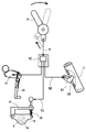
シート5の下方には上方へ開口するラゲージボックス6が設けられ、シート5により開閉されるとともに、シート5はシートロック7により車体側へロックされ、メインスイッチ3と同じキーにより解錠される。また、後述するように、ラゲージボックス6内には、解錠操作部としての操作ノブ8(図1)が設けられ、これにケーブル9の一端が連結され、その他端はジョイント部10を介して車体下部に設けられたメインスタンド収納ロック11へ連結し、これを解錠可能になっている。[0010]
A
【0011】
メインスタンド収納ロック11は、メインスタンド12を収納阻止して盗難防止するためのものであり、メインスタンド収納ロック11を解錠するとメインスタンド12を収納して走行可能となる。また、ジョイント部10からは枝分かれした分岐ケーブル13を介してシャッター開閉機構4へ連結し、メインスタンド収納ロック11の解錠と連動してシャッター開閉機構4を作動させることによりシャッターを開き、メインスイッチ3へキーを挿入してオンにすることができるようになっている。なお、ジョイント部10は、メインスタンド収納ロック11を解錠するために操作ケーブル9を弛めると、分岐ケーブル13も弛めるようになっている。[0011]
The main
【0012】
図3〜5に示すように、メインスイッチ3の上端面に設けられたキー挿入口14の上方を開閉自在に覆うシャッター15は、一端を支軸16によりメインスイッチ3へ回動自在に取付けられ、他端に分岐ケーブル13の一端が連結されている。[0012]
As shown in FIGS. 3 to 5, the
【0013】
分岐ケーブル13は、メインスイッチ3側から一体に延出するステー17の後端に案内され、ステー17とシャッター15の間へ介装された圧縮コイルスプリング18により、シャッター15を図の時計回り方向へ回動付勢している。但し、分岐ケーブル13は解錠操作したとき以外は圧縮コイルスプリング18を圧縮して、キー挿入口14の上方を覆う位置までシャッター15を反時計回り方向へ回動する方向へ引っ張るようになっている。[0013]
The
【0015】
次に、図6〜9に基づき操作レバー及びメインスタンドロックについて説明する。まず図6に示すように、シート5は車体フレーム20の後部に支持されたシートロック7により車体側へロックされ、メインスイッチ3と同じキーによりロック解除される。また、後から詳述するように、ラゲージボックス6内にはロック解除操作部材としての操作ノブ8が設けられ、これに操作ケーブル9の一端が連結され、その他端はメインスタンド12に設けられているメインスタンド収納ロック(後述)へ連結し、これを解除可能になっている。[0015]
Next, the control lever and the main stand lock will be described based on FIGS. First, as shown in FIG. 6, the
【0016】
メインスタンド収納ロックは、駐車中の盗難を防止するための装置であり、シートロック7を解除して操作ノブ8を正規に操作しない限り、メインスタンド12を立てたままにして走行不可能にするものである。一方、操作ノブ8を正規に操作してメインスタンド収納ロックを解除するとメインスタンド12を倒して収納することにより走行可能となる。[0016]
The main stand storage lock is a device for preventing theft while parking, and unless the
【0017】
また、操作ケーブル9は車体フレームの後部の内側に沿って配線され、その途中に設けられたジョイント部10において前記ハンドルロックの分岐ケーブル50が枝分かれしている。ジョイント部10から枝分かれした分岐ケーブル50は、車体フレーム前部に沿って車体カバー内側をハンドルロックまで配線されるとともに、操作ノブ8をロック解除方向へ回動すると、操作ケーブル9と一緒に引かれてロック解除操作するにようになっている。[0017]
Further, the
【0018】
左右の車体フレーム20の中間部間を連結するクロスパイプ22にはスタンドブラケット23が溶接されており、このスタンドブラケット23は周囲に壁部23aを形成して上方へ開口する容器状をなし、その後端部には支軸53を介してメインスタンド12の上端部が回動自在に取付けられ、この上端部をメインスタンド収納ロックでロックするようになっている。メインスタンド12は図示省略の反転スプリングに付勢されて起立位置又は収納位置のいずれかへ選択的に回動する。[0018]
A
【0019】
図7は、ラゲージボックス6の内側後部を前方(図6のB矢示方向)から示す図であり、この図に示すように、支軸24により操作ノブ8をラゲージボックス6の一部を構成する後部壁25の内側へ回動自在に支持している。支軸24の一端は後部壁25を貫通してその後方へ突出し、ここにアーム27が一体に設けられ、その先端に操作ケーブル9の一端を連結している。この操作レバー8の回動は、後部壁25へ取付けられているストッパプレート28の上端部左右に形成されたストッパ斜面28a、28bにより規制する。[0019]
FIG. 7 is a view showing the inside rear of the
【0020】
アーム27の位置は、操作レバー8を図の時計回り方向へ回動させてストッパ斜面28bへ当接させた実線で示すロック位置のとき、操作ケーブル9を引っ張り、反対側へ回動させてストッパ斜面28aへ当接させた仮想線で示すアンロック位置のとき操作ケーブル9を弛めるようになっている。[0020]
Position of the arm 27, when rotates the
【0021】
なお、アーム27の回動方向を反転させることにより、操作レバー8をロック位置又はアンロック位置へ固定する。すなわち、ロック位置又はアンロック位置における操作ケーブル9が支軸24の中心を挟んで反対側を通過するように設定することにより、操作ノブ8を実線で示すロック位置と仮想線で示すアンロック位置との間で回動すると、支軸24の中心を死点としてアーム27の回動方向を反転させ、かつこの反転回動位置で前記並びに操作ケーブル9及び後述するリターンスプリング30の弾力により位置決めする。[0021]
The
【0022】
図中の符号25aはシートの底面に設けられたロック金具26の出入スリットであり、7aはこれに係合するシートロック7のフックである。シートロック7は、車体フレーム20を構成する左右のリヤ部の各上部間に設けられたクロスパイプ20aに取付けてある(図6参照)。[0022]
The reference numeral 25a in the figure is an entrance / exit slit of the
【0023】
次に、メインスタンド収納ロックの詳細を説明する。図8及び図9に示すように、スタンドブラケット23は周囲を壁部で囲むことにより外部から手を入れにくい略密閉空間を形成し、この空間内にメインスタンド収納ロック11を収容してある。[0023]
Next, the details of the main stand storage lock will be described. As shown in FIG. 8 and FIG. 9, the
【0024】
このメインスタンド収納ロック11は、スタンドブラケット23の内部に固定された支持プレート31へ支軸32でその回りへ回動自在に支持されたロックプレート33を備え、このロックプレート33の一端34へ操作ケーブル9とリターンスプリング30の各一端を連結する。リターンスプリング30の他端は支持プレート31へ係止させる。[0024]
The main
【0025】
ロックプレート33の支軸32を挟んで一端34と反対側の端部は係合端部36をなし、補強プレート37及び後部縦壁38の2枚合わせ部分に形成されたブラケット側スリット39へ嵌合し、さらに起立状態にあるメインスタンド12の上部壁40に形成されているスタンド側スリット41へ出入自在である。[0025]
The end opposite to the one
【0026】
スタンド側スリット41は、メインスタンド12が起立状態のときのみブラケット側スリット39と一致し、ロックプレート33の係合端部36が嵌合可能になっている。係合端部36がスタンド側スリット41へ係合すると、メインスタンド12はロックされて回動不能になるため起立状態のままになる。[0026]
The stand side slit 41 matches the bracket side slit 39 only when the
【0027】
リターンスプリング30はロックプレート33を図9の時計回り方向へ常時回動付勢し、係合端部36をスタンド側スリット41から脱出させることにより、図中に仮想線で示すアンロック位置にする。一方、操作ケーブル9は、リターンスプリング30の弾力に抗してロックプレート33を反時計回り方向へ回動させて係合端部36をスタンド側スリット41へ嵌合させることにより、図中に実線で示すロック位置になる。[0027]
The
【0028】
なお、図中の符号42は回動ストッパであり、ロック位置では補強プレート37へ当接し、アンロック位置では支持プレート31の角部43へ当接することにより、ロックプレート33の回動を規制している。[0028]
In the figure,
【0029】
次に、本実施例の作用を説明する。図1に示すように、メインスタンド収納ロック11を解錠させる方向へラゲージボックス6内の操作ノブ8を回動させると、メインスタンド収納ロック11を解錠すると同時にシャッター15を開き、メインスイッチ3のキー挿入口14を開放して図示しないキーを挿入することによりイグニッションスイッチをオンにして走行を可能にする。[0029]
Next, the operation of this embodiment will be described. As shown in FIG. 1, rotates the
【0030】
このように、操作ノブ8を操作するだけでメインスタンド収納ロック11の解錠と同時にシャッター15を開くことができるから、操作が簡単になって操作性が向上するとともに、メインスイッチ3側へシャッター15を開くためのソレノイドのようなアクチュエータを設ける必要がなくなり、構造を簡単にでき、コストダウンが可能になる。そのうえ、シャッター15の開きを同じ盗難防止を目的とするメインスタンド収納ロック11と連動させるので、盗難防止効果を高くすることができる。[0030]
As described above, since the
【0031】
なお、図1に示すように、ジョイント部10から分岐ケーブル50を介してハンドルロックプレート51を連動するようにすることもできる。このようにすれば、ハンドルロックプレート51を直接ハンドルポスト1に形成したスリット52を係合させることができるので、より強力なハンドルロックを構成することができる。[0031]
Note that, as shown in FIG. 1, the
【0033】
なお、本願発明は上記実施例に限定されず種々の変形や応用が可能である。たとえば、メインスイッチ3にハンドルロックを一体化することもできる。また、シャッターの開閉機構やメインスタンド収納ロックは、他の種々な公知構造を採用できる。[0033]
The present invention is not limited to the above embodiment, and various modifications and applications are possible. For example, the steering wheel lock can be integrated with the
【図面の簡単な説明】
【図1】盗難防止装置全体の概念図
【図2】自動2輪車の全体図
【図3】メインスタンドの外観の側面を示す図
【図4】その上面側(図3のA矢示方向)を示す図
【図5】その作用を示す図
【図6】車体後部の要部側面図
【図7】解錠操作部を前方から示す図
【図8】メインスタンド収納ロックを側方から示す図
【図9】図8の9−9線断面図
【符号の説明】1:ハンドルポスト、2:ハンドルポストカバー、3:メインスイッチ、4:シャッター開閉機構、5:シート、6:ラゲージボックス、8:操作ノブ、9:操作ケーブル、10:ジョイント部、11:メインスタンド収納ロック、12:メインスタンド、14:キー挿入口、15:シャッターBrief Description of the Drawings
1 is a conceptual view of the entire antitheft device. FIG. 2 is an overall view of a two-wheeled motorcycle. FIG. 3 is a side view of the appearance of a main stand. Fig. 5 is a view showing the operation thereof. Fig. 6 is a side view of an essential part of a rear portion of the vehicle body. Fig. 7 is a view showing an unlocking operation unit from the front. Fig. 8 is a side view of the main stand storage lock Fig. 9 is a sectional view taken along the line 9-9 in Fig. 8 [Description of Symbols] 1: handle post, 2: handle post cover, 3: main switch , 4: shutter opening and closing mechanism, 5: sheet, 6: luggage box, 8: operation knob, 9: operation cable , 10: joint portion, 11: main stand storage lock, 12: main stand, 14: key insertion slot, 15: shutter
Priority Applications (5)
| Application Number | Priority Date | Filing Date | Title |
|---|---|---|---|
| JP2000023538A JP4267790B2 (en) | 2000-02-01 | 2000-02-01 | Anti-theft device for motorcycles |
| ES200100195A ES2214075B2 (en) | 2000-02-01 | 2001-01-29 | MOTORCYCLE ALARM DEVICE FOR MOTORCYCLE. |
| TW90101943A TW555663B (en) | 2000-02-01 | 2001-01-31 | Anti-theft device for motorcycle |
| IT2001TO000094A ITTO20010094A1 (en) | 2000-02-01 | 2001-01-31 | BURGLAR ALARM DEVICE FOR MOTORCYCLE. |
| CNB011165987A CN1211245C (en) | 2000-02-01 | 2001-02-01 | Theft-proof device for motor bicycle |
Applications Claiming Priority (1)
| Application Number | Priority Date | Filing Date | Title |
|---|---|---|---|
| JP2000023538A JP4267790B2 (en) | 2000-02-01 | 2000-02-01 | Anti-theft device for motorcycles |
Publications (3)
| Publication Number | Publication Date |
|---|---|
| JP2001213370A JP2001213370A (en) | 2001-08-07 |
| JP2001213370A5 true JP2001213370A5 (en) | 2005-01-06 |
| JP4267790B2 JP4267790B2 (en) | 2009-05-27 |
Family
ID=18549681
Family Applications (1)
| Application Number | Title | Priority Date | Filing Date |
|---|---|---|---|
| JP2000023538A Expired - Fee Related JP4267790B2 (en) | 2000-02-01 | 2000-02-01 | Anti-theft device for motorcycles |
Country Status (5)
| Country | Link |
|---|---|
| JP (1) | JP4267790B2 (en) |
| CN (1) | CN1211245C (en) |
| ES (1) | ES2214075B2 (en) |
| IT (1) | ITTO20010094A1 (en) |
| TW (1) | TW555663B (en) |
Families Citing this family (4)
| Publication number | Priority date | Publication date | Assignee | Title |
|---|---|---|---|---|
| ITRM20070191A1 (en) | 2006-04-06 | 2007-10-07 | Suzuki Motor Corp | ELECTRONIC AUTHENTICATION SYSTEM FOR MOTORCYCLE |
| JP4802827B2 (en) * | 2006-04-06 | 2011-10-26 | スズキ株式会社 | Emergency unlocking system for motorcycles |
| JP5764086B2 (en) | 2012-03-28 | 2015-08-12 | 株式会社ホンダロック | Centralized unlocking operation device for vehicle locking mechanism |
| CN108189936A (en) * | 2018-01-19 | 2018-06-22 | 浙江雅迪机车有限公司 | A kind of antitheft opening device of battery case and the electric vehicle with the device |
Family Cites Families (3)
| Publication number | Priority date | Publication date | Assignee | Title |
|---|---|---|---|---|
| JP2871411B2 (en) * | 1993-08-25 | 1999-03-17 | 株式会社東海理化電機製作所 | Vehicle anti-theft device |
| JP3457513B2 (en) * | 1997-07-28 | 2003-10-20 | 朝日電装株式会社 | Cylinder lock protection device |
| DE19753559A1 (en) * | 1997-12-03 | 1999-06-10 | Opel Adam Ag | Anti-theft device for motor vehicles |
-
2000
- 2000-02-01 JP JP2000023538A patent/JP4267790B2/en not_active Expired - Fee Related
-
2001
- 2001-01-29 ES ES200100195A patent/ES2214075B2/en not_active Expired - Fee Related
- 2001-01-31 TW TW90101943A patent/TW555663B/en not_active IP Right Cessation
- 2001-01-31 IT IT2001TO000094A patent/ITTO20010094A1/en unknown
- 2001-02-01 CN CNB011165987A patent/CN1211245C/en not_active Expired - Fee Related
Similar Documents
| Publication | Publication Date | Title |
|---|---|---|
| JP3816290B2 (en) | Scooter type seat mounting structure | |
| JP5286583B2 (en) | Motorcycle | |
| JP5164402B2 (en) | Motorcycle | |
| JP2001260968A (en) | Article storage structure for motor scooter type vehicle | |
| JP2002129807A (en) | Door lock device for vehicle | |
| JP3025198B2 (en) | Remote control type opener for motorcycle | |
| JP2001213370A5 (en) | ||
| JP4267790B2 (en) | Anti-theft device for motorcycles | |
| JP4042954B2 (en) | Open / close lid lock device for vehicle | |
| JP3380309B2 (en) | Storage device for scooter type motorcycle | |
| JP4513068B2 (en) | Luggage storage device for motorcycles | |
| JP5878151B2 (en) | Vehicle smart lock module | |
| JPH08310473A (en) | Motor scooter type motorcycle | |
| JP4267792B2 (en) | Anti-theft device for motorcycles | |
| JP3120855B2 (en) | Motorcycle stand lock device | |
| JP3520265B2 (en) | Motorcycle locking device | |
| JP2000289668A (en) | Lock system of electric moter vehicle | |
| JP4453941B2 (en) | Anti-theft and anti-theft device using motorcycles | |
| JP3544520B2 (en) | Vehicle door latch device | |
| JPH07103736B2 (en) | Door lock device for automobile | |
| JP2800038B2 (en) | Motorcycle storage container opening and closing device | |
| JPS6217571Y2 (en) | ||
| JPH07101368A (en) | Burglar preventing device for motorcycle and motortricycle | |
| JP3564826B2 (en) | Center stand lock device for motorcycles | |
| JP2588777Y2 (en) | Cabin door unlocking device |