JP2001188159A5 - - Google Patents
Download PDFInfo
- Publication number
- JP2001188159A5 JP2001188159A5 JP1999366150A JP36615099A JP2001188159A5 JP 2001188159 A5 JP2001188159 A5 JP 2001188159A5 JP 1999366150 A JP1999366150 A JP 1999366150A JP 36615099 A JP36615099 A JP 36615099A JP 2001188159 A5 JP2001188159 A5 JP 2001188159A5
- Authority
- JP
- Japan
- Prior art keywords
- concave
- gate
- shape
- lens
- concave surface
- Prior art date
- Legal status (The legal status is an assumption and is not a legal conclusion. Google has not performed a legal analysis and makes no representation as to the accuracy of the status listed.)
- Granted
Links
- 230000003287 optical Effects 0.000 description 12
- 238000001514 detection method Methods 0.000 description 4
- 239000011248 coating agent Substances 0.000 description 3
- 238000000576 coating method Methods 0.000 description 3
- 230000015572 biosynthetic process Effects 0.000 description 2
- 238000005755 formation reaction Methods 0.000 description 2
- 238000004519 manufacturing process Methods 0.000 description 2
- 238000000465 moulding Methods 0.000 description 1
- 230000002093 peripheral Effects 0.000 description 1
- 238000004642 transportation engineering Methods 0.000 description 1
Images


Description
この発明は、かかる点に鑑みてなされたもので、プラスチックレンズのゲート位置の検出が容易で、検出精度が向上し、所望の方向に容易に組み付けできて光学性能が安定化した光学系或いは装置を容易に得られるプラスチックレンズ、及びそのプラスチックレンズを低コストで迅速に製造できるプラスチックレンズの製造方法を提供することを目的としている。 The present invention has been made in view of the foregoing, it is easy to detect Gate position of the plastic lens to improve the detection accuracy, the optical system optical performance is stabilized can assembled easily in a desired direction Alternatively, it is an object of the present invention to provide a plastic lens whose device can be easily obtained, and a method of manufacturing the plastic lens which can quickly produce the plastic lens at low cost.
この請求項2乃至請求項5に記載の発明によれば、フランジ部のゲート切断面のゲート位置部分の少なくとも一部が凹面、またはゲート位置部分がすべて凹面、または凹面以外のゲート切断面は、平面または円弧状凸面、またはゲート切断面がすべて凹面であることで、この凹面によってゲート位置が明確になっていることから、プラスチックレンズを光学装置に組み付けるときに、肉眼または検出器により凹面の検出が容易にでき、それによってゲート位置の検出精度が向上する。このため、その凹面を基準にしてプラスチックレンズを一定の方向に容易に、かつ精度よく組み付けることができ、組み付け作業性が向上するとともに、光学性能も安定化する。 According to the invention described in the second to fifth aspects, at least a part of the gate position portion of the gate cutting surface of the flange portion is concave, or all the gate position portions are concave, or the gate cutting surface other than the concave is Since the gate position is made clear by the fact that the flat or arc convex surface or gate cut surface is all concave, when the plastic lens is assembled to the optical device, detection of the concave surface by the naked eye or a detector The gate position detection accuracy is improved. Therefore, the concave surface of the plastic lens easily in a predetermined direction as a reference, and can be assembled accurately, with the assembling operability can be improved, optical performance stabilized.
本明細書でいう『凹面』とは、プラスチックレンズの外形を光軸方向から見た時の形状が凹となる面の全体又はその一部のことを言う。ここで言う凹とは、全体的に見たときに凹であれば良く、微細な形状を問うものではない。例えば、微視的に見たときに一つ又は複数の凸が凹に形成されていたとしても、巨視的に見て凹であれば、ここでいう凹に該当するものである。この凹の一例としては、円弧状、U字状、V字状、コ字状等の種々の形状が挙げられるが、円弧状、U字状、V字状のように、凹の底部が分かり易い形状が好ましい。 The "concave surface" referred to in the present specification means the whole or a part of the surface where the shape of the plastic lens when viewed from the optical axis direction is concave. The term "concave" as used herein is not limited to a fine shape as long as it is concave as a whole. For example, even if one or more convexes are formed to be concave when viewed microscopically, if it is a concave when viewed macroscopically, it corresponds to the concave mentioned here. As an example of this recess, various shapes such as arc shape, U shape, V shape, and U shape can be mentioned, but as in arc shape, U shape and V shape, the bottom portion of the recess can be understood Easy shape is preferred.
また、フランジ部1bのゲート位置部分が凹面であればよく、図2に示すようにゲート位置部分よりゲート切断面1c’を大きく形成してもよい。 Further, the gate position portion of the flange portion 1b may be a concave surface, and as shown in FIG. 2, the gate cut surface 1c ' may be formed larger than the gate position portion.
このようにフランジ部1bのゲート位置部分が凹面であり、この凹面はフランジ部1bの仮想外周面1dに対してレンズ光軸O1側に凹となる窪んだ形状であるので、この凹面によってその位置が明確になっている。 As described above, the gate position portion of the flange portion 1b is a concave surface, and this concave surface is a concave shape which is concave toward the lens optical axis O 1 with respect to the virtual outer peripheral surface 1d of the flange portion 1b. The position is clear.
また、光学機能部11aのゲート位置部分が凹面であればよく、図4に示すようにゲート位置部分よりゲート切断面11c’を大きく形成してもよい。
Further, the gate position portion of the optical function part 11a may be a concave surface, and as shown in FIG. 4, the
また、図3及び図4に示す実施の形態においては、ゲート切断面11c,11c’が曲面とした。これにより、凹面の形成を含めたゲート切断面11c,11c’の形成が容易になっている。特にその曲面がプラスチックレンズ11を光軸方向から見たときに円弧状であることで、凹面となるゲート切断面11c,11c’をエンドミル切断機等により容易に加工できる。
Further, in the embodiment shown in FIG. 3 and FIG. 4, the
また、この円弧状は半径1mm以下の円の一部であることが好ましく、ゲート切断面11c,11c’をエンドミル切断機等により容易に加工でき、光学機能部11aを必要以上に削りすぎないようにすることができる。
The arc shape is preferably a part of a circle having a radius of 1 mm or less, and the
また、凹面は、以上の実施の形態のように、成形時に形成されたゲート部12の切断の際に形成されることが好ましく、それによりレンズ製造を迅速に行うことができる。尚、図4に示した実施の形態においては、ゲート切断面11c’をすべて凹面としたが、ゲート位置部分が凹面に形成されればそれ以外は任意の形状としても良い。
The concave surface is preferably formed at the time of cutting of the
この実施の形態では、凹面21c1以外の切断面21cが円弧状凸面(プラスチックレンズの外周に沿った円孤状)に形成した例を示したが、図6に示すように切断面21c’を平面状に形成してもよいし、凹面21c1’の曲率半径を小さく形成してもよい。
In this embodiment, the
このように光学機能部31aのゲート切断面31c’のゲート位置部分の少なくとも一部が凹面31c1’を形成したので、ゲート位置が明確になり、ゲート位置部分の肉眼及び検出器による検出精度が向上し、凹面31c1’を基準にしてプラスチックレンズを一定の方向に容易に、かつ精度よく組み付けることができ、レンズ性能が安定化し、組み付けの作業性も向上する。
Thus, since at least a part of the gate position portion of the
この実施の形態では、凹面31c1以外のゲート切断面31cが円弧状凸面(プラスチックレンズの外周に沿った円弧状)に形成した例を示したが、図8に示すように切断面31c’を平面状に形成してもよいし、凹面31c1’の曲率半径を小さく形成してもよい。
In this embodiment, the gate cut
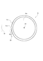
次に、前記したプラスチックレンズ1,11,21,31の凹面には、図9に示すように、凹面41cの底部P1とレンズ光軸O3とを結んだ直線L1と、ゲート位置部分の両側とレンズ光軸O3とを結んだ直線L2,L3とがなす角が、10度の角度θ1,θ2の範囲内となる。凹面41cの底部P1が10度の角度θ1,θ2の範囲に位置することで、凹面の底部がほぼゲート中心位置を示すことになり、これによりゲート部42のゲー卜中心位置が一段と明確になり、特にこの凹面の底部を基準にしてプラスチックレンズ41を組み付けることで、精度よく組み付けることができ、レンズ性能が一段と安定化する。
Next, as shown in FIG. 9, a straight line L1 connecting the bottom P1 of the
また更に、凹面とすることによって、必要以上に余分な切断をしなくてよいようになる(例えばフランジ部の大部分をそのまま残すことができる)ので、コーティングの際の保持具やレンズ搬送用の収納ケースのレンズ保持部分からレンズが離脱したり、場合によっては、コーティング時の保持具に対してレンズが偏ってコーティング不良になるといった問題を防止しうるという効果も得られる。 Furthermore, by making it concave, unnecessary cutting is unnecessary (for example, most of the flange portion can be left as it is), so it is possible to use for holding of the coating or for lens transportation. It is also possible to prevent the problem that the lens is detached from the lens holding portion of the storage case, and in some cases, the lens may be biased against the holder at the time of coating to cause coating defects.
Priority Applications (2)
| Application Number | Priority Date | Filing Date | Title |
|---|---|---|---|
| JP36615099A JP4273378B2 (en) | 1999-12-24 | 1999-12-24 | Plastic lens and manufacturing method thereof |
| US09/740,818 US6466376B2 (en) | 1999-12-24 | 2000-12-21 | Plastic lens and production method thereof |
Applications Claiming Priority (1)
| Application Number | Priority Date | Filing Date | Title |
|---|---|---|---|
| JP36615099A JP4273378B2 (en) | 1999-12-24 | 1999-12-24 | Plastic lens and manufacturing method thereof |
Publications (3)
| Publication Number | Publication Date |
|---|---|
| JP2001188159A JP2001188159A (en) | 2001-07-10 |
| JP2001188159A5 true JP2001188159A5 (en) | 2005-06-09 |
| JP4273378B2 JP4273378B2 (en) | 2009-06-03 |
Family
ID=18486048
Family Applications (1)
| Application Number | Title | Priority Date | Filing Date |
|---|---|---|---|
| JP36615099A Expired - Lifetime JP4273378B2 (en) | 1999-12-24 | 1999-12-24 | Plastic lens and manufacturing method thereof |
Country Status (2)
| Country | Link |
|---|---|
| US (1) | US6466376B2 (en) |
| JP (1) | JP4273378B2 (en) |
Families Citing this family (29)
| Publication number | Priority date | Publication date | Assignee | Title |
|---|---|---|---|---|
| US8556967B2 (en) | 1999-04-09 | 2013-10-15 | Faezeh Mona Sarfarazi | Interior bag for a capsular bag and injector |
| US20030078658A1 (en) | 2001-01-25 | 2003-04-24 | Gholam-Reza Zadno-Azizi | Single-piece accomodating intraocular lens system |
| JP2003156601A (en) * | 2001-11-22 | 2003-05-30 | Fuji Photo Optical Co Ltd | Optical small-size lens |
| DE10250540B3 (en) * | 2002-10-29 | 2004-07-15 | Infineon Technologies Ag | Process for producing an optoelectronic component |
| JP2004205697A (en) * | 2002-12-24 | 2004-07-22 | Fuji Photo Film Co Ltd | Photographic lens |
| JP4502581B2 (en) * | 2003-01-14 | 2010-07-14 | パナソニック株式会社 | Lens system optical device |
| US7217112B2 (en) * | 2003-05-27 | 2007-05-15 | Faezeh Mona Sarfarazi | Mold for intraocular lens |
| US8057217B2 (en) * | 2004-09-30 | 2011-11-15 | Bausch + Lomb Incorporated | Apparatus and method for injection molding an intraocular lens device |
| JP4847020B2 (en) * | 2005-01-19 | 2011-12-28 | 日立マクセル株式会社 | Lens device |
| US20080166501A1 (en) * | 2005-02-23 | 2008-07-10 | Picodeon Ltd Oy | Pulsed Laser Deposition Method |
| US20060227436A1 (en) * | 2005-04-08 | 2006-10-12 | Chen Wen C | Lens of image capture device |
| JP4709626B2 (en) * | 2005-09-30 | 2011-06-22 | 富士フイルム株式会社 | Lens device |
| CN101308237B (en) * | 2007-05-17 | 2010-07-14 | 亚洲光学股份有限公司 | Lens erection system capable of controlling lens phase |
| CN101386113A (en) * | 2007-09-14 | 2009-03-18 | 鸿富锦精密工业(深圳)有限公司 | Method for shearing optical elements |
| EP2316047B1 (en) * | 2008-08-18 | 2011-12-07 | Qioptiq Photonics GmbH & Co. KG | Method for producing a lens |
| USD616005S1 (en) * | 2009-04-09 | 2010-05-18 | Foxsemicon Integrated Technology, Inc. | Optical lens |
| JP5459760B2 (en) * | 2009-08-24 | 2014-04-02 | ダイハツ工業株式会社 | Vehicle lamp |
| CN102576139A (en) * | 2009-09-29 | 2012-07-11 | 柯尼卡美能达精密光学株式会社 | Lens and lens processing method |
| JP2011258254A (en) * | 2010-06-07 | 2011-12-22 | Hoya Corp | Lens and pickup device |
| JP5836610B2 (en) * | 2011-03-04 | 2015-12-24 | キヤノン株式会社 | Plastic optical member and manufacturing method thereof |
| JPWO2012127550A1 (en) * | 2011-03-22 | 2014-07-24 | パナソニック株式会社 | Plastic lens, manufacturing method thereof, and imaging apparatus using the same |
| WO2012132597A1 (en) * | 2011-03-31 | 2012-10-04 | 南部化成株式会社 | Die device for multilayer molding and multilayer molded article |
| JP6429434B2 (en) * | 2012-05-23 | 2018-11-28 | キヤノン株式会社 | Plastic optical member and manufacturing method thereof |
| TWI484240B (en) | 2013-10-04 | 2015-05-11 | Largan Precision Co Ltd | Optical lens assembly |
| US10220150B2 (en) * | 2014-02-10 | 2019-03-05 | Mitsubishi Gas Chemical Company, Inc. | Manufacturing method of syringe barrel |
| FR3028795B1 (en) | 2014-11-21 | 2017-05-05 | Plastic Omnium Cie | PROCESS FOR OBTAINING BY INJECTION AND CUTTING A PIECE OF A MOTOR VEHICLE IN POLYMERIC MATERIAL |
| TWI614518B (en) | 2016-05-09 | 2018-02-11 | 大立光電股份有限公司 | Imaging lens assembly and electronic device |
| US20180364438A1 (en) * | 2017-06-15 | 2018-12-20 | Intel Corporation | Flat non-optical surface of an optical component |
| TWI637208B (en) | 2017-10-27 | 2018-10-01 | 大立光電股份有限公司 | Imaging lens element, camera module, and electronic device |
Family Cites Families (6)
| Publication number | Priority date | Publication date | Assignee | Title |
|---|---|---|---|---|
| JPH1076415A (en) * | 1996-09-03 | 1998-03-24 | Fuji Photo Optical Co Ltd | Periphery working device for molded optical part |
| US6144500A (en) * | 1997-03-05 | 2000-11-07 | Asahi Kogaku Kogyo Kabushiki Kaisha | Plastic lens |
| JPH10272702A (en) * | 1997-03-28 | 1998-10-13 | Fuji Photo Optical Co Ltd | Optical lens and production thereof |
| JPH1114804A (en) * | 1997-06-27 | 1999-01-22 | Fuji Photo Optical Co Ltd | Plastic lens |
| JP4001986B2 (en) * | 1997-10-02 | 2007-10-31 | フジノン株式会社 | Plastic optical lens |
| JPH11119005A (en) * | 1997-10-08 | 1999-04-30 | Fuji Photo Optical Co Ltd | Plastic lens |
-
1999
- 1999-12-24 JP JP36615099A patent/JP4273378B2/en not_active Expired - Lifetime
-
2000
- 2000-12-21 US US09/740,818 patent/US6466376B2/en not_active Expired - Lifetime
Similar Documents
| Publication | Publication Date | Title |
|---|---|---|
| JP2001188159A5 (en) | ||
| JP4273378B2 (en) | Plastic lens and manufacturing method thereof | |
| US8310536B2 (en) | Shape measurement apparatus and shape measurement method | |
| JPH10307247A (en) | Plastic molded lens | |
| JP2005534058A5 (en) | ||
| CN101398523A (en) | Lens barrel assembly | |
| US7052386B2 (en) | Curved surface cutting processing method | |
| TWI738013B (en) | Retaining ring, lens module and electronic device | |
| JPS6159418A (en) | Rotary polygon mirror | |
| US6709159B2 (en) | Bearing structure | |
| US20090268321A1 (en) | Side mirror assembly for a motor vehicle | |
| US20210063616A1 (en) | Prism for optical imaging system | |
| JPH10246847A (en) | Lens barrel provided with mold aspherical lens | |
| JPS59113409A (en) | Polarizing mirror | |
| JP2005128267A (en) | Optical fiber collimator and its manufacturing method | |
| JPH0123782Y2 (en) | ||
| US6510362B1 (en) | Method of determining the trajectory of the groove to be machined in the edge of a lens to be fitted to a “metal supra” type spectacle frame | |
| EP0278638B1 (en) | Improved lens | |
| JP4464756B2 (en) | Multi-optical axis photoelectric sensor mounting structure, mounting method, and mounting fixture used therefor | |
| JP4418860B2 (en) | Lens mold, method of cutting the same, and method of manufacturing lens using the same | |
| JP2003121716A (en) | Lens | |
| JP2004217491A (en) | Optical element | |
| JPH08122508A (en) | Reflection plate and polygon mirror formed by using the same | |
| JPH04294315A (en) | Optical device | |
| JPH03130715A (en) | Manufacture of rotary polygon mirror |