JP2000250120A5 - - Google Patents
Download PDFInfo
- Publication number
- JP2000250120A5 JP2000250120A5 JP1999047669A JP4766999A JP2000250120A5 JP 2000250120 A5 JP2000250120 A5 JP 2000250120A5 JP 1999047669 A JP1999047669 A JP 1999047669A JP 4766999 A JP4766999 A JP 4766999A JP 2000250120 A5 JP2000250120 A5 JP 2000250120A5
- Authority
- JP
- Japan
- Prior art keywords
- focus detection
- detection area
- focus
- display
- lcd
- Prior art date
- Legal status (The legal status is an assumption and is not a legal conclusion. Google has not performed a legal analysis and makes no representation as to the accuracy of the status listed.)
- Granted
Links
- 238000001514 detection method Methods 0.000 description 69
- 230000004397 blinking Effects 0.000 description 2
- 238000010586 diagram Methods 0.000 description 1
- 238000005375 photometry Methods 0.000 description 1
- 230000035945 sensitivity Effects 0.000 description 1
Images

Description
【特許請求の範囲】
【請求項1】ファインダ視野内に複数の焦点検出領域をスーパーインポーズ表示する表示手段を有し、前記焦点検出領域を任意に選択可能にする焦点検出領域手動選択モードを少なくとも持つファインダ内表示装置において、
前記焦点検出領域手動選択モードにおいて、前記焦点検出領域が選択されている際は、前記表示手段に現在選択されている焦点検出領域及び該焦点検出領域以外の焦点検出領域をスーパーインポーズ表示させると共に、現在選択されている焦点検出領域と該焦点検出領域以外の焦点検出領域の表示形態を異ならせる表示制御手段を有することを特徴とするファインダ内表示装置。
【請求項2】前記表示制御手段は、現在選択されている焦点検出領域を点滅表示させ、該焦点検出領域以外の焦点検出領域を点灯表示させることを特徴とする請求項1記載のファインダ内表示装置。
【請求項3】前記表示制御手段は、現在選択されている焦点検出領域の表示形状と、該焦点検出領域以外の焦点検出領域の表示形状を異ならせることを特徴とする請求項1記載のファインダ内表示装置。
【請求項4】前記表示制御手段は、現在選択されている焦点検出領域の表示輝度と、該焦点検出領域以外の焦点検出領域の表示輝度を異ならせることを特徴とする請求項1記載のファインダ内表示装置。
【請求項5】前記表示制御手段は、現在選択されている焦点検出領域の表示の色と、該焦点検出領域以外の焦点検出領域の表示の色を異ならせることを特徴とする請求項1記載のファインダ内表示装置。
【請求項6】前記表示制御手段は、前記焦点検出領域の選択が為された後は、予め定められた時間が経過すると前記焦点検出領域の表示を消灯することを特徴とする請求項1ないし5のいずれかに記載のファインダ内表示装置。
[Claims]
1. A display device in a finder having a display means for superimposing a plurality of focus detection areas in a finder field of view, and at least having a focus detection area manual selection mode that enables the focus detection area to be arbitrarily selected. In
In the focus detecting area manual selection mode, when the focus detection area is selected, the focus detection area other than the focus detection area is currently selected on the display unit and the focal point detection area causes superimposed display A display device in a finder, comprising a display control means for differentiating the display form of the currently selected focus detection area and the focus detection area other than the focus detection area.
2. The display in the finder according to
3. The finder according to
4. The finder according to
5. The display control means according to
Wherein said display control means, after the selection of the focus detection area is made,
【0009】
【課題を解決するための手段】上記目的を達成するために、本発明は、ファインダ視野内に複数の焦点検出領域をスーパーインポーズ表示する表示手段を有し、前記焦点検出領域を任意に選択可能にする焦点検出領域手動選択モードを少なくとも持つファインダ内表示装置において、前記焦点検出領域手動選択モードにおいて、前記焦点検出領域が選択されている際は、前記表示手段に現在選択されている焦点検出領域及び該焦点検出領域以外の焦点検出領域をスーパーインポーズ表示させると共に、現在選択されている焦点検出領域と該焦点検出領域以外の焦点検出領域の表示形態を異ならせる表示制御手段を有するファインダ内表示装置とするものである。
0009
[Means for Solving the Problems] In order to achieve the above object, the present invention has a display means for superimposing a plurality of focus detection areas in a finder field, and arbitrarily selects the focus detection areas. in at least with viewfinder display device focus detection area manual selection mode to allow, in the focus detecting area manual selection mode, when the focus detection area is selected, the currently selected focus detection on the display means In a finder having a display control means for displaying a region and a focus detection region other than the focus detection region in a superimpose manner and differentizing the display form of the currently selected focus detection region and the focus detection region other than the focus detection region. It is used as a display device.
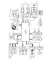
前記LCD駆動回路105は、スーパーインポーズ用LCD21,ファインダ内LCD23,モニター用LCD44を表示駆動させるための公知の回路であり、CPU100からの信号に従い、各LCDの表示内容を制御する。前記IRED駆動回路106は、赤外発光ダイオード(IRED15a〜15f)を状況に応じて選択的に点灯させる。前記LED駆動回路111は、照明用LED24(F−LED)及びスーパーインポーズ用LED19(SI−LED)を点灯制御する。
The
図3は、スーパーインポーズ用LCD21の全表示セグメントの内容を示した図である。
FIG. 3 is a diagram showing the contents of all display segments of the
同図において、50〜94は、焦点検出を行うための45組のラインセンサCCD−1〜CCD−45に対応し、レンズ合焦時、あるいは、後述する焦点検出領域選択手段または視線検出により選択された焦点検出領域をファインダ視野内にスーパーインポーズ表示するための焦点検出領域セグメントである。これらの焦点検出領域セグメントの内いずれかがスーパーインポーズ表示されることにより、選択された焦点検出領域の確認を行える。21aは前記セグメントにLCD駆動回路105からの信号を伝達するための不図示のプリント基板とのコネクト部である。
In the figure, 50 to 94 correspond to 45 sets of line sensors CCD-1 to CCD-45 for performing focus detection, and are selected at the time of lens focusing or by focus detection area selection means or line-of-sight detection described later. It is a focus detection area segment for superimposing the determined focus detection area in the viewfinder field of view. By displaying one of these focus detection region segments in superimpose, the selected focus detection region can be confirmed.
尚、焦点検出領域手動選択モードを選択し、焦点検出領域切換えスイッチSW−Cがオンされているときは、図7に示すように現在選択されている焦点検出領域のみ点滅表示とし、他の焦点検出領域は点灯表示とすることで、全焦点検出領域に対する現在選択されている焦点検出領域の位置を把握できるようにしている。また、ファインダ視野外の表示も焦点検出領域選択モードが手動選択モードであることが判るように、シャッタスピード表示部41にSELの表示を、絞り表示部42にAFの表示を、それぞれ行う。そして、所定時間経過後、前記焦点検出領域及びファインダ視野外の表示を消する。 When the focus detection area manual selection mode is selected and the focus detection area changeover switch SW-C is turned on, only the currently selected focus detection area is displayed in a blinking manner as shown in FIG. 7, and other focal points are displayed. By lighting the detection area, the position of the currently selected focus detection area with respect to the full focus detection area can be grasped. Further, SEL is displayed on the shutter speed display unit 41 and AF is displayed on the aperture display unit 42 so that the focus detection area selection mode can be seen as the manual selection mode for the display outside the field of view of the finder. Then, after a lapse of a predetermined time, the display outside the focus detection area and the finder field of view is turned off.
次に、確定された焦点検出領域において、自動焦点検出回路103は焦点検出演算を行い、焦点検出可能であるか否かを判定し(#109)、不能であればCPU100はLCD駆動回路105に信号を送って図4のファインダ内LCD23の合焦マーク40を点滅させ、焦点検出がNGであることを撮影者に警告する。一方、焦点検出が可能であり、所定のアルゴリズムで選択された焦点検出領域または視線検出により選択された焦点検出領域、または、手動で選択した焦点検出領域の焦点調節状態が合焦でなければ、CPU100はレンズ焦点調節回路109に信号を送って所定量撮影レンズ1を駆動させる(#110)。
Next, in the determined focus detection region, the automatic
レンズ駆動後は、撮影レンズ1が合焦しているか否かの判定を行う(#111)。所定の焦点検出領域において撮影レンズ1が合焦していたならば、CPU100はLCD駆動回路105に信号を送ってスーパーインポーズ用LCD21及びファインダ内LCD23の制御を行い、さらにLED駆動回路111にも信号を送って、F−LED24及びSI−LED19を点灯させることによってそれぞれ、図4中の合焦マーク40及び焦点検出領域自動選択モードを選択時は合焦している焦点検出領域50〜94の少なくとも一つ以上を、焦点検出領域手動選択モード及び視線検出モード時は、選択されている焦点検出領域をスーパーインポーズ表示することによって、撮影レンズが合焦状態にあることと、合焦している焦点検出領域の位置を撮影者に知らしめる。また同時に、CPU100は測光回路102に信号を送信して測光を行わせる(#112)。
After driving the lens, it is determined whether or not the photographing
次に、撮影者が該焦点検出領域位置でのピント状態と測光値を容認しているか否かの判定をスイッチSW1のON,OFFで判定し(#113)、さらにレリーズ釦が押し込まれてスイッチSW2がONされているかどうかの判定を行い、スイッチSW2がOFF状態であれば再びスイッチSW1の状態の確認を行う(#114)。また、スイッチSW2がONされたならばCPU100はシャッタ制御回路107,モータ制御回路108,絞り駆動回路110にそれぞれ信号を送信する。具体的には、まずモータM2に通電し、主ミラー2をアップさせ、絞り26を絞り込んだ後、マグネットMG1に通電してシャッタ4の先幕を開放する。絞り26の絞り値及びシャッタ4のシャッタスピードは、前記測光回路102にて検知された露出値とフィルム5の感度から決定される。所定のシャッタ秒時経過後、マグネットMG2に通電し、前記シャッタ4の後幕を閉じる。フィルム5への露光が終了すると、前記モータM2に再度通電し、ミラーダウン,シャッタチャージを行うと共にモータM1にも通電し、フィルムの1駒送りを行い、一連のシャッタレリーズシーケンスの動作が終了する(#115)。その後、カメラは再びスイッチSW1がONされるまで待機する(#101)。
Next, it is determined by ON / OFF of the switch SW1 whether or not the photographer accepts the focus state and the metering value at the focus detection region position (# 113), and the release button is further pushed to switch. It is determined whether or not SW2 is ON, and if the switch SW2 is in the OFF state, the state of the switch SW1 is confirmed again (# 114). When the switch SW2 is turned on, the
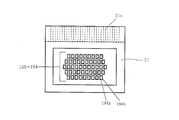
図8に、スーパーインポーズ用LCD21の全表示セグメントの内容を示す。
FIG. 8 shows the contents of all display segments of the
21aは前記セグメントにLCD駆動回路105からの信号を伝達するための不図示のプリント基板とのコネクト部である。
また、実施の第1の形態では、現在選択されている焦点検出領域を点滅表示とし、他の焦点検出領域を点灯表示としているが、逆であっても良い。 Further, in the first embodiment, the currently selected focus detection area is displayed in blinking and the other focus detection area is displayed in lighting, but the opposite may be true.
【符号の説明】
1 撮影レンズ
6 焦点検出装置
12 眼球
19 高輝度LED
21 スーパーインポーズ用LCD
23 ファインダ内LCD
24 照明用LED
50〜94,150〜194 焦点検出領域セグメント
200 LEDアレイ
[Explanation of symbols]
1 Shooting lens 6 Focus detector 12 Eyeball 19 High-brightness LED
21 Super Impose LCD
23 LCD in the finder
24 LED for lighting
50-94 , 150-194 Focus detection area segment 200 LED array
Priority Applications (1)
| Application Number | Priority Date | Filing Date | Title |
|---|---|---|---|
| JP4766999A JP4365925B2 (en) | 1999-02-25 | 1999-02-25 | Display device in the viewfinder |
Applications Claiming Priority (1)
| Application Number | Priority Date | Filing Date | Title |
|---|---|---|---|
| JP4766999A JP4365925B2 (en) | 1999-02-25 | 1999-02-25 | Display device in the viewfinder |
Publications (3)
| Publication Number | Publication Date |
|---|---|
| JP2000250120A JP2000250120A (en) | 2000-09-14 |
| JP2000250120A5 true JP2000250120A5 (en) | 2006-04-13 |
| JP4365925B2 JP4365925B2 (en) | 2009-11-18 |
Family
ID=12781683
Family Applications (1)
| Application Number | Title | Priority Date | Filing Date |
|---|---|---|---|
| JP4766999A Expired - Fee Related JP4365925B2 (en) | 1999-02-25 | 1999-02-25 | Display device in the viewfinder |
Country Status (1)
| Country | Link |
|---|---|
| JP (1) | JP4365925B2 (en) |
Families Citing this family (4)
| Publication number | Priority date | Publication date | Assignee | Title |
|---|---|---|---|---|
| JP2002365519A (en) * | 2001-06-04 | 2002-12-18 | Fuji Photo Optical Co Ltd | Device for detecting state of focusing |
| EP2894845B1 (en) | 2003-12-15 | 2018-06-13 | Canon Kabushiki Kaisha | Camera, camera system and lens apparatus |
| JP5548403B2 (en) * | 2009-07-07 | 2014-07-16 | キヤノン株式会社 | Finder device for optical equipment |
| JP5409205B2 (en) * | 2009-08-31 | 2014-02-05 | キヤノン株式会社 | Imaging apparatus and control method thereof |
-
1999
- 1999-02-25 JP JP4766999A patent/JP4365925B2/en not_active Expired - Fee Related
Similar Documents
| Publication | Publication Date | Title |
|---|---|---|
| CN101206382B (en) | Image-taking apparatus | |
| JPH07128705A (en) | Camera | |
| JP2000250120A5 (en) | ||
| JPH0667086A (en) | Optical device with glance detecting function | |
| JPH07306486A (en) | Camera | |
| JP4365925B2 (en) | Display device in the viewfinder | |
| JPH07146433A (en) | Optical device having sight line detecting function, and camera | |
| JP3890098B2 (en) | Optical device | |
| JP3805025B2 (en) | camera | |
| JPH112862A (en) | Optical device and camera | |
| JP4054436B2 (en) | Optical device | |
| JP4756721B2 (en) | Camera focus detection device | |
| JP2576215Y2 (en) | Camera with viewfinder eyepiece position display function | |
| JP2004012503A (en) | Camera | |
| JP2005249831A (en) | Optical equipment having line-of-sight detector | |
| JPH01279215A (en) | Multipoint distance measuring camera | |
| JPH01271716A (en) | Multipoint range-finding camera | |
| JP3406945B2 (en) | Optical device with gaze detection function | |
| JPH046015Y2 (en) | ||
| JP2000131599A (en) | Device and camera having line-of-sight selecting function | |
| JPH08166629A (en) | Display device for camera | |
| JP2774659B2 (en) | Device to prevent red eye | |
| JPH11218837A (en) | Camera | |
| JPH0924024A (en) | Visual axis detecting device and apparatus having visual axis detecting means | |
| JPH02126211A (en) | Automatic focusing device |