JP2000094499A5 - - Google Patents
Download PDFInfo
- Publication number
- JP2000094499A5 JP2000094499A5 JP1998286041A JP28604198A JP2000094499A5 JP 2000094499 A5 JP2000094499 A5 JP 2000094499A5 JP 1998286041 A JP1998286041 A JP 1998286041A JP 28604198 A JP28604198 A JP 28604198A JP 2000094499 A5 JP2000094499 A5 JP 2000094499A5
- Authority
- JP
- Japan
- Prior art keywords
- handle
- mold
- preform
- neck
- injection
- Prior art date
- Legal status (The legal status is an assumption and is not a legal conclusion. Google has not performed a legal analysis and makes no representation as to the accuracy of the status listed.)
- Granted
Links
- 238000002347 injection Methods 0.000 description 13
- 239000007924 injection Substances 0.000 description 13
- 239000000498 cooling water Substances 0.000 description 4
- 238000000465 moulding Methods 0.000 description 4
- 238000001746 injection moulding Methods 0.000 description 3
- 238000001816 cooling Methods 0.000 description 2
- 238000000071 blow moulding Methods 0.000 description 1
- 230000000875 corresponding Effects 0.000 description 1
- 238000001125 extrusion Methods 0.000 description 1
- 239000000463 material Substances 0.000 description 1
- 239000011347 resin Substances 0.000 description 1
- 229920005989 resin Polymers 0.000 description 1
Images
Description
本発明の他の目的は、バリのない取手を有するプリフォーム及びその成形方法並びに取手付き容器及びその成形方法を提供することにある。 Another object of the present invention is to provide a preform and the molding method and the handled container and its molding method that has a handle with no burrs.
(取手付きプリフォームの説明)
先ず、図1(A)(B)(C)を参照して取手付きプリフォームについて説明する。取手付きプリフォーム100は大別して、プリフォーム本体110と取手部120とを有する。プリフォーム本体110は、図1(B)に示すように、ネック部112と、その下方に続く胴部114と、胴部114の下端を閉鎖する底部116とを有する。図1(B)では、底部116にはゲート痕116Aが残存しているが、これは取手付きプリフォーム100の射出成形後にカットされても良い。
(Explanation of preform with handle)
First, the preform with a handle will be described with reference to FIGS. 1 (A), (B), and (C). The
取手部120は、図1(A)、(B)に示すように、ネック部112より側方に向けて水平に延びる基部122と、基部122よりさらに側方に向けて水平に延びかつ中央に中空領域123を有する中空リング部124と、基部122より中空リング部114の中空領域125を横切って形成されて、中空リング部124の自由端部124A側と基部122とを連結する連結部126とを有する。
このような取手付きボトル130にあっては、取手部120が連結部126にて強度的に補強されていることに加えて、ショートショットも防止されているため機械的強度はさらに高まっている。このため、ボトル本体132内に内容物が充填された状態で取手部120を把持して取手付きボトル130を持ち上げても、取手部120の破損を防止できる。
In such a handle bottle 130, in addition to the
ブロー成形部44は、図3に示すように、割型からなるブローキャビティ型48と図示しない底型とを有する。ブローキャビティ型48には、取手付きプリフォーム100のネック部112を保持するネックホルダー(図示せず)が設けられている。そして、ネックホルダーにて取手付きプリフォーム100のネック部112を保持した状態で、取手付きプリフォーム100内に高圧エアーを吹込み、延伸ロッド(図示せず)を延伸駆動することで、ブローキャビティ型48及び底型の形状に沿った取手付きボトル130を例えば一つずつ延伸ブロー成形するようになっている。
As shown in FIG. 3, the blow molding unit 44 has a blow cavity mold 48 made of a split mold and a bottom mold (not shown). The blow cavity type 48 is provided with a neck holder (not shown) for holding the
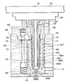
図5に示すように、射出コア押え板54とネックキャビティ型56との間には、4本の射出コア型58を取り付けた射出コア固定板60と、取手付きプリフォーム100を取り出すためのエジェクトプレート62とが取り付けられている。なお、射出コア型58は中空とされ、その内部に冷却パイプ58Aが配置されている。この冷却パイプ58Aの内外の各通路58B,58Cに冷却水が循環される。また、射出キャビティ型68の周囲にも冷却水の通路68Bが形成され、冷却水が循環されるようになっている。これら通路58B,58C,68Bに、図4の回転軸52を通して冷却水を循環させることで、取手付きプリフォーム100を冷却するようになっている。
As shown in FIG. 5, between the injection
また、図5に示すように、射出成形部22の機台10には、1組の射出コア型58及びネックキャビティ型56に対応して射出キャビティ型68が固定配置されている。
Further, as shown in FIG. 5, the machine base 10 of the
射出コア型58、ネックキャビティ型56及び射出キャビティ型68を型締めすることで、取手付きプリフォーム100の本体110を規定するプリフォーム本体成形用キャビティ70が形成される。
Injection core mold 5 8, by clamping the
そして、回転盤18に設けた射出コア型58及びネックキャビティ型56と、射出キャビティ型68とを、型締めし、成形樹脂材料を射出することでネック部112に取手部120を有する有底筒状の取手付きプリフォーム100が成形されることとなる。
Then, the
なお、ネックキャビティ型56及び射出キャビティ型の取手成形用キャビティ72と対応する位置には、それぞれ対向方向にばね82によって構成された押出しピン84が設けられ、型開時に取手部120を、ネックキャビティ型56及び射出キャビティ型68から離すようになっている。
Incidentally, at a position corresponding to the
Priority Applications (1)
| Application Number | Priority Date | Filing Date | Title |
|---|---|---|---|
| JP28604198A JP4162776B2 (en) | 1998-09-22 | 1998-09-22 | Preform with handle and container with handle |
Applications Claiming Priority (1)
| Application Number | Priority Date | Filing Date | Title |
|---|---|---|---|
| JP28604198A JP4162776B2 (en) | 1998-09-22 | 1998-09-22 | Preform with handle and container with handle |
Publications (3)
| Publication Number | Publication Date |
|---|---|
| JP2000094499A JP2000094499A (en) | 2000-04-04 |
| JP2000094499A5 true JP2000094499A5 (en) | 2005-11-04 |
| JP4162776B2 JP4162776B2 (en) | 2008-10-08 |
Family
ID=17699214
Family Applications (1)
| Application Number | Title | Priority Date | Filing Date |
|---|---|---|---|
| JP28604198A Expired - Lifetime JP4162776B2 (en) | 1998-09-22 | 1998-09-22 | Preform with handle and container with handle |
Country Status (1)
| Country | Link |
|---|---|
| JP (1) | JP4162776B2 (en) |
Families Citing this family (2)
| Publication number | Priority date | Publication date | Assignee | Title |
|---|---|---|---|---|
| ES2199629B1 (en) * | 2001-03-30 | 2005-05-01 | Guillermo Caballero De Lujan | PERFECTED PREFORM FOR PACKAGING. |
| CN114179302A (en) * | 2021-12-08 | 2022-03-15 | 广东星联精密机械有限公司 | Design method of eccentric forming assembly |
-
1998
- 1998-09-22 JP JP28604198A patent/JP4162776B2/en not_active Expired - Lifetime
Similar Documents
| Publication | Publication Date | Title |
|---|---|---|
| EP0232207B1 (en) | Synthetic-resin hollow container with grip and method of molding the same | |
| KR960010303B1 (en) | Bottle with ear | |
| US6733716B2 (en) | Method of making a stretch/blow molded article (bottle) with an integral projection such as a handle | |
| US10391698B2 (en) | Method for forming a container by moving the handle during blowing | |
| JP4714509B2 (en) | Injection stretch blow molding method | |
| JPH0439023A (en) | Manufacturing method and device for synthetic resin vessel with handle | |
| EP1095756A3 (en) | Injection stretch blow molding apparatus | |
| JP3677690B2 (en) | Stretch blow molding method for hollow molded products such as lighting gloves | |
| JPH0694158B2 (en) | Preform for molding a can body made of synthetic resin and method for manufacturing a can body made of synthetic resin using the same | |
| BR0012657B1 (en) | apparatus for blow molding hollow plastic containers, and method for inserting and locking a preform at a predetermined position in a pair of half blow molds. | |
| JP6736124B2 (en) | Method for manufacturing pressure-resistant container, preform and container used in the manufacturing method | |
| JPH0571002B2 (en) | ||
| JP2000094499A5 (en) | ||
| JP7166439B2 (en) | Cooling mold, manufacturing apparatus and manufacturing method for resin molded product | |
| ATE267685T1 (en) | DEVICE FOR BLOW MOLDING CONTAINERS TO WHICH HANDLES ARE MOLDED AND WITH IMPROVED HANDLE TRANSPORT DEVICE | |
| JP3577996B2 (en) | Method and apparatus for manufacturing biaxially stretch blow molded container | |
| JP2000043128A5 (en) | Molding method and mold for synthetic resin containers | |
| JP2005007598A (en) | Fine-mouthed cylindrical container and injection stretch blow molding method therefor | |
| JPH07205997A (en) | Method and apparatus for molding synthetic resin container with handle | |
| JPH05131443A (en) | Injection mold for preform having undercut in lip part and synthetic resin vessel | |
| JPH0436939B2 (en) | ||
| JP4162776B2 (en) | Preform with handle and container with handle | |
| US6402503B1 (en) | Plastic injection molding apparatus | |
| JPH0749216B2 (en) | Method and apparatus for molding synthetic resin container with handle | |
| JP2000167916A (en) | Die for molding bottle |