【発明の名称】チャイルドシートのロック装置及びチャイルドシート
【特許請求の範囲】
【請求項1】車両のシートベルト装置のウェビングによってチャイルドシートを車両の座席に固定するためのロック装置であって、
ウェビングをクランプするためのクランプローラと、
該クランプローラとの間で該ウェビングを挟み付ける押え面とを有するチャイルドシートのロック装置において、
該クランプローラは、その軸心線が上下方向となるように配置されると共に、チャイルドシートの右側に傾いた右傾斜姿勢と左側に傾いた左傾斜姿勢とをとりうるように傾動可能とされており、
前記押え面として、該クランプローラが右傾斜姿勢をとったときに該クランプローラと対峙する第1の押え面と、該クランプローラが左傾斜姿勢をとったときに該クランプローラと対峙する第2の押え面とが設けられていることを特徴とするチャイルドシートのロック装置。
【請求項2】請求項1において、前記クランプローラを前記傾斜姿勢をとらせるように回動させるためのハンドルを備えていることを特徴とするチャイルドシートのロック装置。
【請求項3】請求項2において、前記クランプローラが左傾斜姿勢、右傾斜姿勢及びこれらの中間の中立姿勢をとったときにそれぞれ各姿勢にクランプローラを保持する位置決め手段が設けられていることを特徴とするチャイルドシートのロック装置。
【請求項4】請求項3において、前記クランプローラを傾動可能に支持するクランプベースを備え、該クランプベースに前記位置決め手段としてのスプリングが取り付けられていることを特徴とするチャイルドシートのロック装置。
【請求項5】請求項4において、前記押え面はチャイルドシートのベースバックの凹部に設けられており、前記クランプベースは該凹部に対面して該ベースバックに取り付けられていることを特徴とするチャイルドシートのロック装置。
【請求項6】請求項1ないし5のいずれか1項に記載のチャイルドシートのロック装置を備えてなるチャイルドシート。
【発明の詳細な説明】
【0001】
【発明の属する技術分野】
本発明は、シートベルト装置のウェビングによってチャイルドシートを車両の座席に固定するためのロック装置に係り、特にこのウェビングをクランプローラでクランプするようにしたロック装置に関する。また、本発明は、このロック装置を備えたチャイルドシートに関する。
【0002】
【従来の技術】
自動車の座席にチャイルドシートを設置する場合、通常、このチャイルドシートを大人用シートベルト装置のウェビングによって固定する。イギリス特許公開公報GB2288202Aでは、このウェビングをクランプするためにクランプローラが用いられている。このクランプローラは、ローラ外周面にローラ軸心線と平行方向に延在する凸条が設けられており、このローラと対峙する段付き面との間でシートベルト装置のショルダーウェビングを挟みつけてクランプする。
【0003】
ところで、シートベルト装置のショルダーウェビングをクランプローラで挟む場合、クランプローラのローラ軸心線方向がウェビングの幅方向と略直交する必要がある。このショルダーウェビングは、自動車の座席のシートバックに沿って右上り又は左上りに斜めに引き回される。即ち、ショルダーウェビングの先端は車体の中央側のバックルに装着されたトングに連なっており、ショルダーウェビングの後端側は車体のピラーの上部に掛止されている。そのため、自動車の左座席にチャイルドシートを載せた場合、ショルダーウェビングは左上りに引き回され、右座席に載せた場合、ショルダーウェビングは右上りに引き回される。
【0004】
上記のGB2288202Aでは、左上りのショルダーウェビングをロックするための左側クランプ装置と、右上りのショルダーウェビングをロックするための右側クランプ装置との2個のクランプ装置を用いている。
【0005】
【発明が解決しようとする課題】
本発明は1個のクランプローラによって左上りのショルダーウェビング及び右上りのショルダーウェビングのいずれをもクランプすることができるチャイルドシートのロック装置と、このロック装置を備えたチャイルドシートとを提供することを目的とする。
【0006】
【課題を解決するための手段】
本発明のチャイルドシートのロック装置は、車両のシートベルト装置のウェビングによってチャイルドシートを車両の座席に固定するためのロック装置であって、ウェビングをクランプするためのクランプローラと、該クランプローラとの間で該ウェビングを挟み付ける押え面とを有するチャイルドシートのロック装置において、該クランプローラは、その軸心線が上下方向となるように配置されると共に、チャイルドシートの右側に傾いた右傾斜姿勢と左側に傾いた左傾斜姿勢とをとりうるように傾動可能とされており、前記押え面として、該クランプローラが右傾斜姿勢をとったときに該クランプローラと対峙する第1の押え面と、該クランプローラが左傾斜姿勢をとったときに該クランプローラと対峙する第2の押え面とが設けられていることを特徴とするものである。
【0007】
かかる本発明のロック装置にあっては、クランプローラをチャイルドシートの左側及び右側のいずれにも傾けることができ、左上り及び右上りのいずれのショルダーウェビングについても1個のクランプローラでクランプすることができる。
【0008】
本発明では、このクランプローラを前記傾斜姿勢をとらせるように回動させるためのハンドルを備えていることが好ましい。
【0009】
このクランプローラが左傾斜姿勢、右傾斜姿勢及びこれらの中間の中立姿勢をとったときにそれぞれ各姿勢にクランプローラを保持する部材、例えば位置決め用スプリングが設けられていてもよい。
【0010】
本発明では、このクランプローラを傾動可能に支持するクランプベースを備え、該クランプベースに前記位置決め用スプリングが取り付けられていても良い。この押え面はチャイルドシートのベースバックの凹部に設けられており、前記クランプベースは該凹部に対面して該ベースバックに取り付けられていても良い。
【0011】
本発明のチャイルドシートは、かかる本発明のロック装置を備えたものである。
【0012】
【発明の実施の形態】
以下図1〜9を参照して本発明の実施の形態を詳細に説明する。
【0013】
図9に示す通り、この実施の形態に係るロック装置を備えたチャイルドシートは、チャイルドシートベース10と、このチャイルドシートベース10に装着されるシート本体12とを備えている。チャイルドシートベース10は、ベース底部10aと、該ベース底部10aから立ち上がるベースバック10bとを備えており、このベースバック10bの高さ方向の中間部分かつ左右幅方向の中間部分にシートベルト装置のショルダーウェビング20をクランプするためのクランプ装置22が設けられている。なお、ベースバック10bの左右の端部には、このショルダーウェビング20が係止されるフック14が設けられている。また、このベースバック10bの下部には、ラップウェビング18を通すためのフック16が設けられている。
【0014】
シートベルト装置は、このショルダーウェビング20を巻き取るためのリトラクタ(図示略)を備えており、ショルダーウェビング20は自動車のBピラー等に設けられたスルーアンカーに掛けられている。ウェビング18,20は連続したウェビングよりなるものであり、その途中部分がタング24に挿通されている。このタング24はシートベルト装置のバックル26に装着される。
【0015】
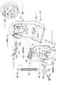
次に、上記のクランプ装置22の構成について詳細に説明する。図1に示す通り、このクランプ装置22は、クランプローラ30と、このクランプローラ30を支持するクランプベース40と、該クランプベース40を覆うカバー60と、クランプローラ30を左右に傾動させるためのハンドル80とを備えている。クランプローラ30は、ローラ軸心線方向を上下方向にしてクランプベース40に装着される。このクランプローラ30の上端及び下端からはそれぞれ上軸32と下軸34とが突設されている。このローラ30の外周面にはローラ軸心線と平行方向に延在する多数の突条が設けられている。なお、突条はアヤ目状のものであっても良い。
【0016】
クランプベース40は、図2に明瞭に示される通り、下部起立面42と、上部起立面46と、これらの起立面42,46同士を連結する連結面44と、上部起立面46の上端から張り出された張出片48とを備えている。この張出片48には、上軸32の挿通孔50が設けられている。この上軸挿通孔50は、クランプベース40の幅方向に延在する長孔よりなる。前記連結面44には、下軸34の挿通孔59が設けられている。
【0017】
上部起立面46には、後述するカバー60の突起が係合する開口51,52と、ビス53の挿通用の孔54とが設けられている。下部起立面42の上端からは、該下部起立面42と面一状となるように上方に突片55Aが立設され、この突片55Aにビス挿通孔55が設けられている。なお、下部起立面42にもビス挿通孔56が設けられている。
【0018】
上部起立面46からは、前記ビス挿通孔54と同軸的に筒状の突部57(図1参照)が設けられている。
【0019】
前記カバー60は、この突部57を受け入れる開口67を備えている。また、クランプベース40の開口51,52に入り込む突起61,62がこの開口67の近傍に設けられている。
【0020】
このカバー60には、クランプベース40の連結面44の下側に配置されるローラ受け64が設けられている。このローラ受け64は略U字形状に湾曲した軸受部64aによって前記ローラ30の下軸34を支承する。
【0021】
カバー60の上部には、ローラ30の位置決め用のスプリング70を取り付けるためのスプリング支持孔72が設けられている。このスプリング支持孔72の上側に、カバー60の左右幅方向に円弧状に延在するレバー挿通孔74が設けられている。
【0022】
前記ハンドル80は、このカバー60に重なるように配置され、スリップキャップ82及び前記ビス53によって回動自在に支持される。なお、ビス53はスリップキャップ82の中心穴82aを通ってハンドル80のビス捻じ込み穴84に捻じ込まれる。このスリップキャップ82は、前記突部57に内嵌される。
【0023】
ハンドル80の上部からはレバー86が突設されており、このレバー86の先端に形成された切欠部88が前記上軸32と係合可能とされている。即ち、このレバー86がカバー60のレバー挿通孔74に挿通され、クランプベース40の張出片48の上側に張り出す。そして、切欠部88が上軸32と係合しハンドル80の回動によってローラ30が左右方向に傾動される。
【0024】
前記スプリング70は、このローラ30の上軸32と係合する中立部70Nと、左右の押え部70A,70Bを備えている。ローラ30の軸心線が上下方向となっている時には、上軸32は中立部70Nに係合している。ハンドル80によってローラ30が傾動された場合、スプリング70を撓ませながらローラ30が回動し、押え部70A又は70Bと係合することにより、ローラ30が傾動状態に維持される。
【0025】
このクランプ装置22は、前記の通りチャイルドシートベース10のベースバック10bに対し取り付けられる。この取り付けは前記ビス挿通孔55,56に挿通されたビスをベースバック10bに捻じ込むことにより行われる。
【0026】
図1に示す通り、ベースバック10bには、クランプベース40の突片54が入り込む溝90が設けられ、この溝90内にビスの捻じ込み穴92が設けられている。また、溝90,90の中間の下方位置にも別のビス捻じ込み穴94が設けられている。
【0027】
このベースバック10bに固定されたクランプ装置22のローラ30が入り込む凹部96が該ベースバック10bに設けられている。そして、左側又は右側に傾動したローラ30と対面する押え面としての斜面98A,98Bが形成されている。この斜面98A,98B同士は、上部ほど両者の間隔が広くなるようにV字形に配置されている。この斜面98A,98Bとクランプ装置22とによってロック装置が構成される。
【0028】
このように構成されたロック装置を有するチャイルドシートは、これを自動車の座席の上に載せ、シートベルト装置のウェビングによって固定される。
【0029】
この固定を行うには、図9に示すように、ショルダーウェビング20を上側のフック14に掛け、ラップウェビング18を下側のフック16に掛け、タング24をバックル26に装着する。そして、チャイルドシートを自動車の右側座席に載せたときには、図5,7に示すようにハンドル80をA方向に回す。
【0030】
そうすると、ローラ30がA方向に傾き、ショルダーウェビング20が右側の斜面98Aとローラ30との間に挟み込まれる。この場合、ウェビング20がリトラクタによって図5のR方向に引かれるときには、ウェビング20からローラ30に対し該ローラ30を斜面98Aから離反させる方向に力が加えられるので、ウェビング20はローラ30と斜面98Aとの間を通過し、リトラクタによって巻き取られる。これにより、ウェビングの緩みが除去される。
【0031】
ウェビングを図5の矢印F方向に引っ張った場合には、ウェビング20とローラ30の外周面との摩擦により、ローラ30に対し矢印A方向の力が加えられ、ローラ30と斜面98Aとの間でウェビング20が強力に挟み込まれるので、ウェビング20がF方向に引き取られることが防止される。この結果、ローラ30とトング24との間にショルダーウェビング20がピンと張り、ラップウェビング18もピンと張った状態となり、チャイルドシートが車両の座席にしっかりと固定される。
【0032】
チャイルドシートを自動車の左側座席に載せた場合には、ショルダーウェビング20は図9の2点鎖線で示されるように引き回される。この場合には、ハンドル80をB方向に回す。そうすると、図6及び8に示す通り、ローラ30と斜面98Bとの間でウェビング20が挟持される。この場合も、ウェビング20はリトラクタに巻き取られるR方向にはローラ30,斜面98B間を通過するが、矢印F方向にはローラ30と斜面98Bとの間で挟み込まれ、ローラ30、斜面98B間を通過することが阻止される。
【0033】
このようにこのロック装置によると、チャイルドシートを左右いずれの座席に載せた場合にあっても、ハンドル80を左又は右に回すことによって、ショルダーウェビング20を強固にクランプし、チャイルドシートを車両の座席に対ししっかりと取り付けることができる。
【0034】
【発明の効果】
以上の通り、本発明のロック装置及びチャイルドシートによると、チャイルドシートを自動車の左右いずれの座席に載せた場合であっても、1個のクランプ装置を有するロック装置によって、このチャイルドシートを座席にしっかりと取り付けることが可能である。従って、このロック装置及びチャイルドシートは、クランプ装置が1個で足りるため、装置構成コストが安価なものとなる。
【図面の簡単な説明】
【図1】実施の形態に係るロック装置の分解斜視図である。
【図2】図1とは反対側から見たクランプ装置の分解斜視図である。
【図3】クランプベース,ローラ及びハンドルの係合関係を示す分解斜視図である。
【図4】(a)図はローラが中立状態にある場合のローラと斜面との関係を示す斜視図である。(b)図は(a)図のIVb−IVb線に沿う断面図である。
【図5】ローラをA方向に傾動させた状態のローラと斜面98Aとの係合関係を示す斜視図である。
【図6】ローラをB方向に傾動させた場合のローラと斜面98Bとの係合関係を示す斜視図である。
【図7】ローラをA方向に傾動させた場合のクランプ装置の模式的な正面図である。
【図8】ローラをB方向に傾動させた場合のクランプ装置の模式的な正面図である。
【図9】実施の形態に係るロック装置を備えたチャイルドシートの斜視図である。
【符号の説明】
10 チャイルドシートベース
10b ベースバック
20 ショルダーウェビング
22 クランプ装置
24 タング
26 バックル
30 クランプローラ
32 上突軸
34 下突軸
40 クランプベース
50 上軸挿通穴
59 下軸挿通穴
60 カバー
64 ローラ受け
74 レバー挿通穴
80 ハンドル
86 レバー
98A,98B 斜面(押え面)Patent application title: Child seat locking device and child seat
1. A locking device for securing a child seat to a vehicle seat by means of a webbing of a vehicle seat belt device, comprising:
A clamp roller for clamping the webbing,
In a child seat lock device having a pressing surface for holding the webbing between the clamp roller and the clamp roller,
The clamp roller is disposed so that its axial center line is in the vertical direction, and can be tilted so as to be able to take a right-inclined attitude inclined to the right of the child seat and a left-inclined attitude inclined to the left. ,
As the pressing surface, a first pressing surface that faces the clamp roller when the clamp roller takes the right inclined posture, and a second pressing surface that faces the clamp roller when the clamp roller takes the left inclined posture A locking device for a child seat, characterized in that a pressing surface of the child seat is provided.
2. The child seat locking device according to claim 1, further comprising a handle for turning the clamp roller so as to assume the inclined posture.
3. The positioning apparatus according to claim 2, further comprising: positioning means for holding the clamp roller in each posture when the clamp roller takes a left inclined posture, a right inclined posture and a neutral posture between them. Child seat locking device characterized by
4. A child seat locking device according to claim 3, further comprising: a clamp base for supporting the clamp roller in a tiltable manner, wherein a spring as the positioning means is attached to the clamp base.
5. The child seat according to claim 4, wherein the pressing surface is provided in a recess of a base back of the child seat, and the clamp base is attached to the base back facing the recess. Lock device.
6. A child safety seat comprising the child safety seat locking device according to any one of claims 1 to 5.
Detailed Description of the Invention
[0001]
Field of the Invention
The present invention relates to a locking device for securing a child seat to a vehicle seat by webbing of a seat belt device, and more particularly to a locking device adapted to clamp the webbing with a clamp roller. The invention also relates to a child seat provided with this locking device.
[0002]
[Prior Art]
When installing a child seat in a car seat, the child seat is usually fixed by the webbing of an adult seat belt device. In UK Patent Publication GB 2288202A, a clamp roller is used to clamp the webbing. The clamp roller is provided with a ridge extending in the direction parallel to the roller axial center line on the outer peripheral surface of the roller, and the shoulder webbing of the seat belt device is held between the stepped surface facing the roller Clamp.
[0003]
By the way, when the shoulder webbing of the seat belt device is pinched by the clamp roller, it is necessary for the roller axial center line direction of the clamp roller to be substantially orthogonal to the width direction of the webbing. The shoulder webbing is drawn obliquely to the upper right or upper left along the seat back of the car seat. That is, the tip of the shoulder webbing is continued to the tongue attached to the buckle on the center side of the vehicle body, and the rear end side of the shoulder webbing is hooked on the top of the pillar of the vehicle body. Therefore, when the child seat is put on the left seat of the car, the shoulder webbing is drawn to the upper left, and when put on the right seat, the shoulder webbing is drawn to the upper right.
[0004]
The above-mentioned GB2288202A uses two clamp devices, a left clamp device for locking the upper left shoulder webbing and a right clamp device for locking the upper right shoulder webbing.
[0005]
[Problems to be solved by the invention]
It is an object of the present invention to provide a child seat locking device capable of clamping both upper left shoulder webbing and upper right shoulder webbing by a single clamp roller, and a child seat provided with this locking device. Do.
[0006]
[Means for Solving the Problems]
The child seat locking device of the present invention is a locking device for securing the child seat to the vehicle seat by the webbing of the seat belt device of the vehicle, and is between the clamping roller for clamping the webbing and the clamping roller. In a child seat locking device having a pressing surface for holding the webbing, the clamp roller is disposed such that its axial center line is in the vertical direction, and is inclined to the right and to the left with the right inclination of the child seat. And the first pressing surface which faces the clamp roller when the clamp roller is in the right tilt position, and the clamp roller as the press surface. A second pressing surface facing the clamp roller when the vehicle is in the left inclined posture And it is characterized in Rukoto.
[0007]
In such a locking device according to the present invention, the clamp roller can be inclined to either the left side or the right side of the child seat, and both upper left and right upper shoulder webbings can be clamped by one clamp roller. it can.
[0008]
In the present invention, it is preferable to have a handle for turning the clamp roller so as to take the inclined position.
[0009]
The clamp roller may be provided with a member for holding the clamp roller in each posture, for example, a positioning spring, when the clamp roller has a left inclined posture, a right inclined posture, and a neutral posture in between.
[0010]
In the present invention, a clamp base that tiltably supports the clamp roller may be provided, and the positioning spring may be attached to the clamp base. The pressing surface may be provided in a recess of the base back of the child seat, and the clamp base may be attached to the base back facing the recess.
[0011]
The child seat of the present invention is provided with the lock device of the present invention.
[0012]
BEST MODE FOR CARRYING OUT THE INVENTION
An embodiment of the present invention will be described in detail below with reference to FIGS.
[0013]
As shown in FIG. 9, the child restraint provided with the locking device according to this embodiment comprises a child restraint base 10 and a seat body 12 mounted on the child restraint base 10. The child seat base 10 includes a base bottom portion 10a and a base back 10b rising from the base bottom portion 10a. The shoulder webbing of the seat belt device is at an intermediate portion in the height direction and an intermediate portion in the lateral width direction of the base back 10b. A clamping device 22 for clamping 20 is provided. In addition, the hook 14 by which this shoulder webbing 20 is latched is provided in the edge part on the right and left of the base back 10b. Further, a hook 16 for passing the lap webbing 18 is provided below the base back 10b.
[0014]
The seat belt device includes a retractor (not shown) for winding the shoulder webbing 20. The shoulder webbing 20 is hooked on a through anchor provided on a B-pillar or the like of a car. The webbings 18 and 20 are formed of a continuous webbing, and the middle part thereof is inserted into the tongue 24. The tongue 24 is attached to a buckle 26 of a seat belt device.
[0015]
Next, the configuration of the clamp device 22 described above will be described in detail. As shown in FIG. 1, the clamp device 22 includes a clamp roller 30, a clamp base 40 for supporting the clamp roller 30, a cover 60 for covering the clamp base 40, and a handle for tilting the clamp roller 30 to the left and right. It has 80 and. The clamp roller 30 is mounted on the clamp base 40 with the roller axial center line oriented in the vertical direction. An upper shaft 32 and a lower shaft 34 project from the upper end and the lower end of the clamp roller 30, respectively. The outer peripheral surface of the roller 30 is provided with a number of protrusions extending in a direction parallel to the roller axis. The ridges may be in the form of an eyelid.
[0016]
As clearly shown in FIG. 2, the clamp base 40 extends from the upper end of the lower rising surface 42, the upper rising surface 46, the connecting surface 44 connecting the rising surfaces 42 and 46, and the upper end of the upper rising surface 46. And a projecting piece 48. An insertion hole 50 for the upper shaft 32 is provided in the overhanging piece 48. The upper shaft insertion hole 50 is an elongated hole extending in the width direction of the clamp base 40. The connection surface 44 is provided with an insertion hole 59 for the lower shaft 34.
[0017]
The upper standing surface 46 is provided with openings 51 and 52 with which projections of a cover 60 described later engage and holes 54 for insertion of the screws 53. A projecting piece 55A is erected upward from the upper end of the lower rising surface 42 so as to be flush with the lower rising surface 42, and a screw insertion hole 55 is provided in the protruding piece 55A . In addition, a screw insertion hole 56 is also provided in the lower rising surface 42.
[0018]
A cylindrical protrusion 57 (see FIG. 1) is provided coaxially with the screw insertion hole 54 from the upper standing surface 46.
[0019]
The cover 60 is provided with an opening 67 for receiving the projection 57. Further, protrusions 61 and 62 which enter into the openings 51 and 52 of the clamp base 40 are provided in the vicinity of the opening 67.
[0020]
The cover 60 is provided with a roller receiver 64 disposed below the connecting surface 44 of the clamp base 40. The roller receiver 64 supports the lower shaft 34 of the roller 30 by means of a bearing portion 64a curved in a substantially U-shape.
[0021]
At the top of the cover 60, a spring support hole 72 for mounting a spring 70 for positioning the roller 30 is provided. On the upper side of the spring support hole 72, a lever insertion hole 74 extending in an arc shape in the lateral width direction of the cover 60 is provided.
[0022]
The handle 80 is disposed to overlap the cover 60, and is rotatably supported by the slip cap 82 and the screw 53. The screw 53 is screwed into the screw screw hole 84 of the handle 80 through the central hole 82 a of the slip cap 82. The slip cap 82 is internally fitted to the projection 57.
[0023]
A lever 86 protrudes from the top of the handle 80, and a notch 88 formed at the tip of the lever 86 is engageable with the upper shaft 32. That is, the lever 86 is inserted into the lever insertion hole 74 of the cover 60 and protrudes to the upper side of the overhanging piece 48 of the clamp base 40. Then, the notch 88 is engaged with the upper shaft 32, and the roller 30 is tilted in the left-right direction by the rotation of the handle 80.
[0024]
The spring 70 includes a neutral portion 70N engaged with the upper shaft 32 of the roller 30, and left and right pressing portions 70A and 70B. When the axial center line of the roller 30 is in the vertical direction, the upper shaft 32 is engaged with the neutral portion 70N. When the roller 30 is tilted by the handle 80, the roller 30 is rotated while bending the spring 70 and engaged with the pressing portion 70A or 70B, whereby the roller 30 is maintained in the tilted state.
[0025]
The clamp device 22 is attached to the base back 10b of the child seat base 10 as described above. This attachment is performed by screwing the screw inserted in the screw insertion holes 55, 56 into the base back 10b.
[0026]
As shown in FIG. 1, the base back 10 b is provided with a groove 90 into which the projection 54 of the clamp base 40 is inserted, and a screw threading hole 92 of a screw is provided in the groove 90. Also, another screw threading hole 94 is provided at a lower position between the grooves 90 and 90.
[0027]
The base back 10 b is provided with a recess 96 into which the roller 30 of the clamp device 22 fixed to the base back 10 b is inserted. Further, slopes 98A and 98B are formed as pressing surfaces facing the roller 30 tilted to the left or right. The slopes 98A and 98B are arranged in a V-shape such that the distance between the slopes becomes wider toward the top. The inclined surfaces 98A and 98B and the clamp device 22 constitute a lock device.
[0028]
A child restraint having such a locking device is placed on the seat of the motor vehicle and secured by the webbing of the seat belt device.
[0029]
To do this, as shown in FIG. 9, the shoulder webbing 20 is hooked on the upper hook 14, the lap webbing 18 is hooked on the lower hook 16, and the tongue 24 is attached to the buckle 26. Then, when the child seat is placed on the right side seat of the vehicle, the handle 80 is turned in the A direction as shown in FIGS.
[0030]
Then, the roller 30 is inclined in the A direction, and the shoulder webbing 20 is sandwiched between the inclined surface 98A on the right side and the roller 30. In this case, when the webbing 20 is pulled in the R direction of FIG. 5 by the retractor, a force is applied from the webbing 20 to the roller 30 in a direction to move the roller 30 away from the slope 98A. It passes between and is taken up by the retractor. Thereby, the slack of the webbing is removed.
[0031]
When the webbing is pulled in the direction of arrow F in FIG. 5, the friction between the webbing 20 and the outer peripheral surface of the roller 30 applies a force in the direction of arrow A to the roller 30, and the roller 30 and the slope 98A. Since the webbing 20 is strongly sandwiched, the webbing 20 is prevented from being pulled away in the F direction. As a result, the shoulder webbing 20 is tightened between the roller 30 and the tongue 24, and the lap webbing 18 is also tightened, so that the child safety seat is firmly fixed to the vehicle seat.
[0032]
When the child's seat is placed on the left seat of the vehicle, the shoulder webbing 20 is routed as shown by the two-dot chain line in FIG. In this case, the handle 80 is turned in the B direction. Then, as shown in FIGS. 6 and 8, the webbing 20 is nipped between the roller 30 and the slope 98B. Also in this case, the webbing 20 passes between the roller 30 and the slope 98B in the R direction taken up by the retractor, but is sandwiched between the roller 30 and the slope 98B in the arrow F direction. Are blocked from passing through.
[0033]
Thus, according to this locking device, the shoulder webbing 20 is firmly clamped by turning the handle 80 left or right regardless of whether the child seat is placed on the left or right seat, and the child seat can be fixed to the vehicle seat It can be attached firmly.
[0034]
【Effect of the invention】
As described above, according to the lock device and the child seat of the present invention, the child seat can be firmly attached to the seat by the lock device having one clamping device, regardless of whether the child seat is placed on the left or right seat of the vehicle. It is possible. Therefore, since the lock device and the child seat need only one clamp device, the cost for the device configuration is low.
Brief Description of the Drawings
FIG. 1 is an exploded perspective view of a lock device according to an embodiment.
FIG. 2 is an exploded perspective view of the clamping device viewed from the side opposite to FIG. 1;
FIG. 3 is an exploded perspective view showing an engagement relationship of a clamp base, a roller and a handle.
FIG. 4A is a perspective view showing a relationship between a roller and a slope when the roller is in a neutral state. (B) The figure is a cross-sectional view taken along the line IVb-IVb of (a).
FIG. 5 is a perspective view showing an engagement relationship between the roller and a slope 98A in a state where the roller is tilted in the A direction.
FIG. 6 is a perspective view showing an engagement relationship between the roller and an inclined surface 98B when the roller is tilted in a B direction.
FIG. 7 is a schematic front view of the clamp device when the roller is tilted in the A direction.
FIG. 8 is a schematic front view of the clamp device when the roller is tilted in the B direction.
FIG. 9 is a perspective view of a child seat provided with the lock device according to the embodiment.
[Description of the code]
DESCRIPTION OF SYMBOLS 10 Child seat base 10b Base back 20 Shoulder webbing 22 Clamp device 24 Tongue 26 Buckle 30 Clamp roller 32 Upper projecting shaft 34 Lower projecting shaft 40 Clamp base 50 Upper shaft insertion hole 59 Lower shaft insertion hole 60 Cover 64 Roller support 74 Lever insertion hole 80 Handle 86 Lever 98A, 98B Slope (pressing surface)