FR2858064A1 - Determining parameters of speed and anellipticity, for treating seismic traces from collection at common midpoint including anelliptic obliquity correction - Google Patents
Determining parameters of speed and anellipticity, for treating seismic traces from collection at common midpoint including anelliptic obliquity correction Download PDFInfo
- Publication number
- FR2858064A1 FR2858064A1 FR0308861A FR0308861A FR2858064A1 FR 2858064 A1 FR2858064 A1 FR 2858064A1 FR 0308861 A FR0308861 A FR 0308861A FR 0308861 A FR0308861 A FR 0308861A FR 2858064 A1 FR2858064 A1 FR 2858064A1
- Authority
- FR
- France
- Prior art keywords
- dtn
- obliquity
- offset
- correction
- parameters
- Prior art date
- Legal status (The legal status is an assumption and is not a legal conclusion. Google has not performed a legal analysis and makes no representation as to the accuracy of the status listed.)
- Granted
Links
- 238000012937 correction Methods 0.000 title claims abstract description 101
- 238000013508 migration Methods 0.000 claims abstract description 42
- 230000005012 migration Effects 0.000 claims abstract description 42
- 238000004458 analytical method Methods 0.000 claims abstract description 29
- 230000003068 static effect Effects 0.000 claims abstract description 24
- 238000011282 treatment Methods 0.000 claims abstract description 14
- 238000006243 chemical reaction Methods 0.000 claims abstract description 8
- 238000000034 method Methods 0.000 claims description 39
- 238000004647 photon scanning tunneling microscopy Methods 0.000 claims description 31
- 238000012545 processing Methods 0.000 claims description 13
- 238000004364 calculation method Methods 0.000 claims description 7
- 230000000717 retained effect Effects 0.000 abstract description 4
- VEXRMMJOMMTPKJ-ZVSIBQGLSA-N 1-methyl-3-[(e)-[(1e)-1-(methylcarbamothioylhydrazinylidene)propan-2-ylidene]amino]thiourea Chemical compound CNC(=S)N\N=C\C(\C)=N\NC(=S)NC VEXRMMJOMMTPKJ-ZVSIBQGLSA-N 0.000 abstract 1
- 101100129500 Caenorhabditis elegans max-2 gene Proteins 0.000 abstract 1
- 238000013459 approach Methods 0.000 description 8
- 230000000694 effects Effects 0.000 description 5
- 230000008901 benefit Effects 0.000 description 4
- 238000001914 filtration Methods 0.000 description 3
- 238000010586 diagram Methods 0.000 description 2
- YJQZYXCXBBCEAQ-UHFFFAOYSA-N ractopamine Chemical compound C=1C=C(O)C=CC=1C(O)CNC(C)CCC1=CC=C(O)C=C1 YJQZYXCXBBCEAQ-UHFFFAOYSA-N 0.000 description 2
- 238000005070 sampling Methods 0.000 description 2
- 238000001228 spectrum Methods 0.000 description 2
- 238000012550 audit Methods 0.000 description 1
- 230000009286 beneficial effect Effects 0.000 description 1
- 230000000670 limiting effect Effects 0.000 description 1
- 230000014759 maintenance of location Effects 0.000 description 1
- 238000004519 manufacturing process Methods 0.000 description 1
- 230000002829 reductive effect Effects 0.000 description 1
- 239000013049 sediment Substances 0.000 description 1
- 230000009897 systematic effect Effects 0.000 description 1
- 230000036962 time dependent Effects 0.000 description 1
- 238000010200 validation analysis Methods 0.000 description 1
Classifications
-
- G—PHYSICS
- G01—MEASURING; TESTING
- G01V—GEOPHYSICS; GRAVITATIONAL MEASUREMENTS; DETECTING MASSES OR OBJECTS; TAGS
- G01V1/00—Seismology; Seismic or acoustic prospecting or detecting
- G01V1/28—Processing seismic data, e.g. analysis, for interpretation, for correction
- G01V1/36—Effecting static or dynamic corrections on records, e.g. correcting spread; Correlating seismic signals; Eliminating effects of unwanted energy
-
- G—PHYSICS
- G01—MEASURING; TESTING
- G01V—GEOPHYSICS; GRAVITATIONAL MEASUREMENTS; DETECTING MASSES OR OBJECTS; TAGS
- G01V1/00—Seismology; Seismic or acoustic prospecting or detecting
- G01V1/28—Processing seismic data, e.g. analysis, for interpretation, for correction
-
- G—PHYSICS
- G01—MEASURING; TESTING
- G01V—GEOPHYSICS; GRAVITATIONAL MEASUREMENTS; DETECTING MASSES OR OBJECTS; TAGS
- G01V2210/00—Details of seismic processing or analysis
- G01V2210/50—Corrections or adjustments related to wave propagation
- G01V2210/52—Move-out correction
Abstract
Description
<Desc/Clms Page number 1> <Desc / Clms Page number 1>
Le domaine d'application de l'invention est celui de la prospection sismique. L'invention concerne plus particulièrement le traitement des traces sismiques d'une collection en point milieu commun. The field of application of the invention is that of seismic prospecting. The invention relates more particularly to the treatment of the seismic traces of a collection at common midpoint.
L'invention concerne plus précisément un procédé de détermination des paramètres de vitesse V et d'anellipticité # nécessaires pour réaliser des traitements comprenant une correction d'obliquité des traces sismiques. The invention relates more precisely to a method for determining the parameters of velocity V and of anellipticity # necessary for carrying out treatments comprising an obliquity correction of the seismic traces.
La prospection sismique consiste d'une manière générale, à émettre dans le sous-sol, à l'aide d'une ou plusieurs sources sismiques, des ondes sismiques, à enregistrer en surface, en fonction du temps, des données sismiques correspondant aux ondes sismiques réfléchies sur les interfaces géologiques du sous-sol (encore appelées réflecteurs) à l'aide de récepteurs (encore appelés géophones ou hydrophones selon que l'on prospecte à terre ou en mer) puis à traiter ces données pour en extraire des informations utiles quant à la géologie du sous-sol. Seismic prospecting generally consists of emitting seismic waves in the subsoil, using one or more seismic sources, to record, on a time-dependent basis, seismic data corresponding to the waves. seismic reflections on the geological interfaces of the subsoil (also called reflectors) using receivers (also called geophones or hydrophones depending on whether one prospects on land or at sea) then to treat these data to extract useful information as for the geology of the subsoil.
On appelle trace sismique l'enregistrement de l'énergie sismique réalisé par chaque récepteur durant l'acquisition des données. Seismic trace is the recording of seismic energy made by each receiver during data acquisition.
Une technique classique de prospection sismique est la couverture multiple pour laquelle sources et récepteurs sont agencés de telle sorte qu'un même point milieu (c'est-à-dire le point à égale distance entre la source et le récepteur d'une trace considérée) regroupe plusieurs traces sismiques. A classical seismic survey technique is the multiple coverage for which sources and receivers are arranged such that a same midpoint (ie the point equidistant between the source and the receiver of a trace considered ) groups together several seismic traces.
Si les traces sismiques contiennent des informations utiles quant aux réflexions sismiques et à la géologie du sous-sol, elles contiennent également des composantes de bruit. While the seismic traces contain useful information about seismic reflections and the geology of the subsoil, they also contain noise components.
L'un des premiers objectifs du traitement des données sismiques est d'éliminer, ou tout du moins d'atténuer, ces composantes non désirées de bruit de telle sorte que les informations utiles puissent être clairement identifiées et interprétées. One of the primary goals of seismic data processing is to eliminate, or at least mitigate, these unwanted noise components so that useful information can be clearly identified and interpreted.
Une méthode classiquement utilisée afin d'atténuer ces composantes de bruit est la collection en point milieu commun (ou A method conventionally used to mitigate these noise components is the common mid-point collection (or
<Desc/Clms Page number 2><Desc / Clms Page number 2>
collection CMP selon l'acronyme de l'expression anglo-saxonne Common MidPoint). Les traces disposant d'un même point milieu sont alors regroupées selon la distance séparant source et récepteur (appelée déport ou offset selon la terminologie anglo-saxonne). CMP collection according to the acronym of the Common Common Anglo-Saxon). The traces having the same midpoint are then grouped according to the distance between source and receiver (called offset or offset according to the English terminology).
D'une manière générale, la représentation en image des données sismiques nécessite la mise en oeuvre d'un traitement comprenant : # une opération dite TZO (selon l'acronyme de l'expression anglo- saxonne Transform to Zero Offset) visant à compenser l'effet d'obliquité des trajets en ramenant les temps d'arrivée des réflexions à ceux de traces à déport nul, # ainsi qu'une opération de migration visant à restituer les formes correctes des interfaces géologiques. In general, the image representation of the seismic data requires the implementation of a treatment comprising: # a so-called TZO (Transform to Zero Offset) operation intended to compensate the effect of obliquity of the paths by reducing the arrival times of the reflections to those of zero offset traces, # as well as a migration operation aimed at restoring the correct forms of the geological interfaces.
Si ces opérations de TZO et de migration sont généralement réalisées successivement, elles peuvent aussi être réalisées conjointement. Cela est en particulier le cas lorsque est réalisée une migration temps avant sommation (migration PSTM selon l'acronyme de l'expression anglosaxonne Pre-Stack Time Migration). If these TZO and migration operations are generally performed successively, they can also be performed jointly. This is particularly the case when a time-to-summation migration is performed (PSTM migration according to the acronym for the English expression Pre-Stack Time Migration).
De manière simplifiée, l'opération de TZO permet de simuler l'acquisition des données sismiques par des sources et récepteurs disposés au point milieu commun. In a simplified manner, the TZO operation makes it possible to simulate the acquisition of the seismic data by sources and receivers arranged at the common mid-point.
L'objectif est d'additionner les enregistrements illuminant le même
![]()
point du sous-sol afintl'augmenter le rapport signal sur bruit et le rapport réflexions primaire sur réflexions secondaires, et de bénéficier ainsi des atouts de la couverture multiple . The goal is to add the recordings illuminating the same
![]()
The point of the subsoil is to increase the signal-to-noise ratio and the ratio of primary reflections to secondary reflections, and thus to benefit from the advantages of multiple coverage.
Afin de fabriquer l'image à déport nul, une méthode dite de correction d'obliquité ou NMO (correspondant à l'acronyme de l'expression anglosaxonne Normal Move Out) est mise en oeuvre. In order to manufacture the image with zero offset, a method known as obliquity correction or NMO (corresponding to the acronym for the expression Anglosaxonne Normal Move Out) is implemented.
Si on fait l'hypothèse d'un sous-sol stratifié horizontalement et sans variation latérale des vitesses de propagation, on montre que les enregistrements ayant la propriété d'éclairer le même point du sous-sol sont ceux ayant le même point milieu. Assuming a horizontally stratified subsoil without lateral variation in propagation velocities, it is shown that the recordings having the property of illuminating the same point of the subsoil are those having the same midpoint.
<Desc/Clms Page number 3> <Desc / Clms Page number 3>
Cependant l'image d'une réflexion dans le sous-sol arrive à des temps variables selon le déport. Afin d'additionner les réflexions, il faut donc préalablement corriger les différents enregistrements pour les ramener tous à une référence commune, celle de déport nul. However, the image of a reflection in the subsoil arrives at varying times depending on the offset. In order to add up the reflections, we must first correct the different recordings to bring them all back to a common reference, that of zero offset.
Historiquement, la correction d'obliquité repose sur un modèle particulièrement simple du sous-sol : le modèle homogène avec réflecteurs horizontaux. Historically, the obliquity correction is based on a particularly simple model of the basement: the homogeneous model with horizontal reflectors.
Dans ce modèle, les réflexions associées à chacun des réflecteurs du sous-sol, s'alignent théoriquement le long d'hyperboles, encore appelées indicatrices, centrées à la verticale du point milieu. In this model, the reflections associated with each of the reflectors in the subsoil are theoretically aligned along hyperbolas, also called indicators, centered vertically at the midpoint.
Le temps d'arrivée d'une réflexion est alors une fonction hyperbolique du déport source-récepteur, le temps le plus court étant celui obtenu à déport nul. The arrival time of a reflection is then a hyperbolic function of the source-receiver offset, the shortest time being that obtained at zero offset.
De manière à réaliser la sommation des enregistrements de chaque collection, la correction NMO redresse les hyperboles afin de les amener théoriquement à l'horizontal. In order to perform the summation of the records of each collection, the NMO correction corrects the hyperbolas to bring them theoretically to the horizontal.
La correction NMO est alors réalisée en se basant sur l'équation hyperbolique suivante du temps t de propagation après réflexion, associé à un couple source - récepteur de déport x :

dans laquelle to représente le temps de propagation pour un déport nul et V désigne la vitesse moyenne de propagation des ondes dans le sous-sol. The NMO correction is then carried out based on the following hyperbolic equation of the propagation time t after reflection, associated with a source-receiver pair of offset x:
in which to represents the propagation time for a zero offset and V denotes the average speed of propagation of the waves in the subsoil.
Le modèle simpliste évoqué ci-dessus s'appuie notamment sur des hypothèses telles que de faibles angles d'incidence et un milieu isotrope. The simplistic model mentioned above relies notably on assumptions such as low angles of incidence and an isotropic medium.
Mais les hypothèses du modèle simpliste sont trop restrictives pour décrire un milieu complexe, et ne peuvent en particulier s'appliquer à la propagation des ondes sismiques dans un milieu anisotrope (milieu dans lequel la vitesse des ondes peut varier selon la direction de propagation). But the assumptions of the simplistic model are too restrictive to describe a complex environment, and can not particularly apply to the propagation of seismic waves in an anisotropic medium (medium in which the wave velocity can vary in the direction of propagation).
L'utilisation d'un modèle moins simpliste est rendue nécessaire, en particulier du fait de : The use of a less simplistic model is necessary, in particular because of:
<Desc/Clms Page number 4><Desc / Clms Page number 4>
- l'utilisation de longues flûtes pour l'acquisition en off-shore profond, ce qui conduit en particulier à acquérir des traces à large déport ; - l'observation d'anisotropie dans les sédiments de type argileux. - the use of long flutes for acquisition offshore deep, which leads in particular to acquire traces wide offset; - observation of anisotropy in clay-type sediments.
L'hypothèse généralement acceptée consiste à modéliser un milieu anisotrope comme un empilement de couches isotropes transversalement disposant d'un axe de symétrie vertical. On parle alors d'anisotropie VTI (acronyme de l'expression anglo-saxonne Vertical Transverse Isotropy). The generally accepted hypothesis consists of modeling an anisotropic medium such as a stack of transversely isotropic layers with a vertical axis of symmetry. We then speak of anisotropy VTI (acronym for the English expression Vertical Transverse Isotropy).
Il a ainsi été proposé de déterminer les corrections d'obliquité devant être réalisée en : - introduisant de l'inhomogénéité verticale dans un modèle de milieu
VTI homogène, comme cela a été présenté dans le document ALKHALIFAH, T. et TSVANKIN, 1., 1995, Velocity analysis for transversely isotropic média : Geophysics, 60,1550-1566 ; ou encore, en - introduisant de l'anisotropie VTI dans un modèle à couches isotropiques stratifiées, comme cela a été montré dans le document SILIQI, R. et BOUSQUIE, N., 2000, Anelliptic time processing based on a shifted hyperbola approach, 70th Ann. Internat. Mtg.: Soc. Of
![]()
Expl.Geophys., 2245-2248 . It has thus been proposed to determine the obliquity corrections to be made by: - introducing vertical inhomogeneity in a medium model
Homogeneous VTI, as presented in ALKHALIFAH, T. and TSVANKIN, 1., 1995, Velocity analysis for transversely isotropic media: Geophysics, 60, 1550-1566; or again, by introducing VTI anisotropy in a stratified isotropic layer model, as has been shown in the document SILIQI, R. and BOUSQUIE, N., 2000, Anelliptic time processing based on a shifted hyperbola approach, 70th Ann. Internat. Mtg .: Soc. of
![]()
Expl.Geophys., 2245-2248.
Cette seconde approche, combinant inhomogénéité verticale et anisotropie VTI pour fournir un nouveau modèle du sous-sol, semble la meilleure dans la plupart des cas réels étudiés. This second approach, combining vertical inhomogeneity and VTI anisotropy to provide a new basement model, seems the best in most of the real cases studied.
L'équation suivante de correction par hyperbole décalée anelliptique du temps t de propagation après réflexion, associé à un couple source récepteur de déport x, découle de ce modèle :
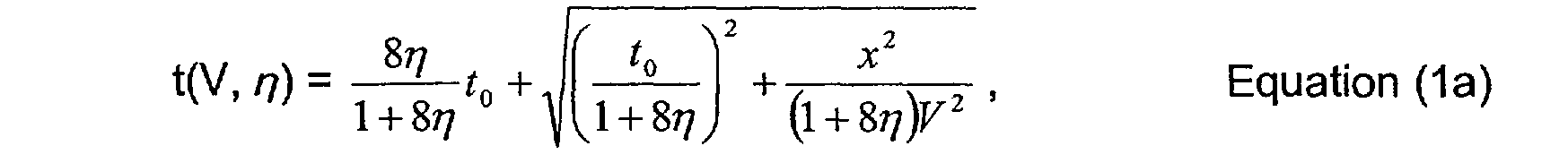
où V représente la vitesse classiquement utilisée en sismique, correspondant à de faibles déports, et # est un paramètre, dit anellipticité. The following equation of antiliptic shifted hyperbole correction of the propagation time t after reflection, associated with an x offset receiver source pair, follows from this model:
where V represents the velocity conventionally used in seismic, corresponding to small offsets, and # is a parameter, called anellipticity.
Il a également été proposé dans le document SUAUDEAU, E. et SILIQI, R., 2001, Anelliptic pre stack time migration, Annual international It has also been proposed in the document SUAUDEAU, E. and SILIQI, R., 2001, Anelliptic pre stack time migration, Annual International
<Desc/Clms Page number 5><Desc / Clms Page number 5>
Meeting, CSEG Expanded Abstracts d'inclure la correction d'obliquité par hyperbole décalée anelliptique dans l'équation du temps de trajet utilisée lors de l'opération de migration PSTM. Meeting, CSEG Expanded Abstracts to include antiliptic offset hyperbole obliquity correction in the travel time equation used during the PSTM migration operation.
L'équation de la migration PSTM s'exprime classiquement sous la forme d'une double hyperbole décalée anelliptique, somme de deux racines carrées (équation DSQR selon l'expression anglo-saxonne Double SQuare Root). The PSTM migration equation is conventionally expressed in the form of a double anelliptic shifted hyperbola, the sum of two square roots (equation DSQR according to the English expression Double SQuare Root).
En tenant compte de l'anellipticité, l'expression de cette équation en déport constant devient la suivante :

où : - les paramètres V et # sont ceux mentionnés ci-dessus,
Xm représente les coordonnées des points milieux, x-xm représente l'ouverture (ou aperture ) de la migration, h représente le demi-déport source - récepteur, to représente le temps double à l'ouverture nulle de l'opérateur. Taking into account the anellipticity, the expression of this constant offset equation becomes the following:
where: - the parameters V and # are those mentioned above,
Xm represents the coordinates of the midpoints, x-xm represents the opening (or aperture) of the migration, h represents the source-receiver half-offset, to represents the double time at the zero opening of the operator.
On notera que lorsque l'ouverture x-xm de la migration est nulle, l'équation (1 b) de correction PSTM devient l'équation (1 a) de correction NMO. La correction d'obliquité NMO constitue ainsi un cas particulier de la
![]()
migration PSTM : cetuude la migration PSTM d'ouverture nulle. Note that when the x-xm aperture of the migration is zero, the PSTM correction equation (1 b) becomes the NMO correction equation (1 a). The obliquity correction NMO thus constitutes a particular case of the
![]()
PSTM migration: this is the zero aperture PSTM migration.
Finalement, afin de réaliser un traitement de données sismique comprenant une correction d'obliquité qui tienne compte de l'hétérogénéité verticale et de l'anisotropie de type VTI, il est donc nécessaire de déterminer les deux paramètres de vitesse V et d'anellipticité #
L'estimation desdits paramètres V et # peut être classiquement réalisée en deux passes telles que : Finally, in order to carry out a seismic data processing comprising an obliquity correction which takes into account the vertical heterogeneity and the VTI type anisotropy, it is therefore necessary to determine the two parameters of velocity V and anellipticity #
The estimation of said parameters V and # can be conventionally carried out in two passes such as:
<Desc/Clms Page number 6><Desc / Clms Page number 6>
au cours de la première passe, la distribution des vitesses V le long de l'axe des temps est estimée en n'utilisant que les données à déports proches ; au cours de la seconde passe, l'anellipticité # est estimée, le long de l'axe des temps, en utilisant : o la distribution des vitesses déterminée au cours de la première passe, et o l'ensemble des données (y compris celles à larges déports). during the first pass, the velocity distribution V along the time axis is estimated using only near-miss data; during the second pass, the # is estimated along the time axis, using: o the velocity distribution determined during the first pass, and o the set of data (including wide-spread).
Il a également été montré dans le document : SILIQI, R., 2001, Technological leap in time processing focuses the data throughout anisotropic media: First Break, 19, n 11, 612-618 , qu'une estimation des paramètres V et il peut être réalisée en une seule passe, au cours de laquelle on réalise des analyses bispectrales permettant de pointer simultanément les deux paramètres V et 1] le long de l'axe des temps, et cela en utilisant toutes les données. It has also been shown in the document: SILIQI, R., 2001, Technological leap in time processing focuses on the data throughout anisotropic media: First Break, 19, No. 11, 612-618, that an estimate of the parameters V and it can be performed in a single pass, during which bispectral analyzes are performed to simultaneously point the two parameters V and 1] along the time axis, using all the data.
Cependant, les analyses denses des paramètres de correction d'obliquité sont préférablement réalisées lorsque l'équation de correction ne dépend plus du temps to (on parle alors de correction d'obliquité statique). However, the dense analyzes of the skew correction parameters are preferably performed when the correction equation no longer depends on the time to (this is called static obliquity correction).
Une correction statique permet effectivement de décaler, pour un déport donné, l'ensemble des échantillons constituant chacune des traces d'un même temps #t. A static correction actually makes it possible to shift, for a given offset, the set of samples constituting each trace of the same time #t.
Ainsi, lorsqu'une correction statique est réalisée, le nombre de calculs devant être effectués peut être significativement réduit et le phénomène d'étirement des traces est éliminé, ce qui rend viables lesdites analyses denses. Thus, when a static correction is made, the number of calculations to be performed can be significantly reduced and the trace stretching phenomenon is eliminated, making said dense analyzes viable.
Seules les analyses de vitesses et d'anellipticité en deux passes peuvent aujourd'hui être mises en oeuvre, en particulier grâce à des approximations paraboliques des résiduelles d'obliquité, de manière à obtenir un pointé dense desdits paramètres V et #. Only analyzes of velocities and anellipticity in two passes can today be implemented, in particular thanks to parabolic approximations of the obliquity residuals, so as to obtain a dense dash of said parameters V and #.
Dans ce cadre : In this context:
<Desc/Clms Page number 7><Desc / Clms Page number 7>
# on estime tout d'abord des vitesses résiduelles, en utilisant les données à faible déport, suite à une première estimation des vitesses ; # on estime ensuite l'anellipticité, sur toutes les données, en utilisant les mises à jour des vitesses réalisée précédemment. # firstly, we estimate residual velocities, using the low offset data, following a first estimation of the velocities; # then all the data are estimated using the speed updates previously performed.
Une loi d'effacement (ou mute selon la terminologie anglosaxonne) doit ainsi être définie, pour l'estimation des vitesses résiduelles, afin de ne conserver parmi l'ensemble des données que celles considérées comme étant à faible déport. An erase law (or mute according to the English terminology) must thus be defined, for the estimation of the residual velocities, in order to keep among the set of data only those considered as being at low offset.
Or l'efficacité de l'analyse en deux passes est particulièrement sensible au choix d'une telle loi d'effacement. But the effectiveness of the two-pass analysis is particularly sensitive to the choice of such an erasure law.
En outre, ce sont les données à large déport qui sont principalement utilisées pour l'estimation de l'anellipticité 77. In addition, it is the large offset data that is mainly used for estimating anellipticity.
Mais, l'estimation de l'anellipticité réalisée pour les données à large déport n'est pas très précise, si bien que la correction réalisée est finalement imprécise. But, the estimation of the anellipticity carried out for the data with large offset is not very precise, so that the correction realized is finally imprecise.
Un but de l'invention est de permettre de s'affranchir de ces limitations et inconvénients, en proposant de réaliser un traitement comprenant une correction d'obliquité statique qui soit plus efficace et plus précis. An object of the invention is to overcome these limitations and disadvantages, proposing to perform a treatment comprising a static obliquity correction that is more efficient and more accurate.
Plus précisément, l'invention a pour objectif la détermination dense des paramètres de vitesse V et d'anellipticité # en une seule passe utilisant l'ensemble des données disponibles, c'est-à-dire en s'appuyant sur l'ensemble de la gamme de déports. More precisely, the aim of the invention is the dense determination of the speed V and anellipticity parameters in a single pass using all the available data, that is to say by relying on the set of the range of offsets.
A cet effet, l'invention propose un procédé de détermination des paramètres de vitesse V et d'anellipticité # pour un traitement de traces sismiques d'une collection à point-milieu commun (CMP) comprenant une correction d'obliquité anelliptique, caractérisé en ce qu'il comporte : une étape préliminaire de définition d'une pluralité de n#uds (dtn,
![]()
'0)' lesdits n#uds étant significatifs de paramètres dtn et t0 représentant respectivement la correction d'obliquité pour le déport For this purpose, the invention proposes a method for determining the speed V and anti-randomness parameters for a seismic trace processing of a common mid-point collection (CMP) comprising an antiliptic obliquity correction, characterized in that what it comprises: a preliminary step of defining a plurality of nodes (dtn,
![]()
'0)' said nodes being significant of parameters dtn and t0 respectively representing the obliquity correction for the offset
<Desc/Clms Page number 8><Desc / Clms Page number 8>
maximal et le temps de propagation à déport nul en coordonnées hyperboliques, ladite étape préliminaire étant suivie pour chacun des n#uds (dtn, #0) définis lors de l'étape préliminaire, des étapes de correction d'obliquité des traces de la collection CMP en fonction des valeurs desdits paramètres dtn et 70 au n#ud considéré, et de calcul de la fonction de semblance associée à ladite correction d'obliquité pour le n#ud considéré ; et # pour chaque temps to de pointé, d'une étape comprenant la

détermination du n#ud (dtn(to), 70 (to de semblance maximale, et d'une étape finale de conversion des paramètres dtn(to) et zo (to) de manière à obtenir les lois de vitesse V(to) et d'anellipticité r7(to). and the zero-offset propagation time in hyperbolic coordinates, said preliminary step being followed for each of the nodes (dtn, # 0) defined during the preliminary step, obliquity correction steps of the traces of the collection CMP based on the values of said parameters dtn and 70 at the considered node, and calculating the semblance function associated with said obliquity correction for the considered node; and # for each time to dotted, a step including the
determination of the n # ud (dtn (to), 70 (to of maximum semblance, and of a final step of conversion of the parameters dtn (to) and zo (to) so as to obtain the laws of speed V (to) and of anellipticity r7 (to).
Selon un premier mode de réalisation de l'invention, le traitement réalisé est une correction d'obliquité NMO statique des traces sismiques. According to a first embodiment of the invention, the processing performed is a static obliquity correction NMO of the seismic traces.
Selon un second mode de réalisation de l'invention, le traitement réalisé est une migration PSTM des traces sismiques, ladite migration PSTM comprenant une correction d'obliquité PSTM statique desdites traces sismiques. According to a second embodiment of the invention, the processing performed is a PSTM migration of the seismic traces, said PSTM migration comprising a static PSTM obliquity correction of said seismic traces.
Un aspect préféré, mais non limitatif, du procédé selon l'invention concerne la définition des paramètres dtn et 70 relativement à la vitesse V et à l'anellipticité #, de manière à assurer des corrections d'obliquité

statiques, selon dtn = r 8zl t + t Z + x 'a" 2 et r0 = -#. 1+877 ' 1 + 8J (l + 87/)F2 1+877
D'autres aspects, buts et avantages de la présente invention apparaîtront mieux à la lecture de la description détaillée suivante, faite en référence aux figures annexées sur lesquelles : - la figure 1a représente l'hyperbole anelliptique décalée permettant de réaliser la correction d'obliquité NMO et illustre la signification des
![]()
paramètres r0 et dtn ; A preferred, but not limiting, aspect of the process according to the invention relates to the definition of the parameters dtn and 70 with respect to the speed V and to the anellipticity #, so as to ensure obliquity corrections.
static, according to dtn = r 8zl t + t Z + x 'a "2 and r0 = - #. 1 + 877' 1 + 8J (l + 87 /) F2 1 + 877
Other aspects, objects and advantages of the present invention will appear better on reading the following detailed description, made with reference to the appended figures in which: FIG. 1a represents the offset antiliptic hyperbole making it possible to perform the obliquity correction; NMO and illustrates the meaning of
![]()
parameters r0 and dtn;
<Desc/Clms Page number 9><Desc / Clms Page number 9>
- la figure 1 b représente l'équation DSQR de la double hyperbole anelliptique décalée de la migration PSTM et illustre la signification des paramètres r0 et dtn ; - la figure 2 illustre l'effet du paramètre r0 sur la courbe de réflexion corrigée par la correction NMO ; - les figures 3a et 3b représentent le volume d'analyse (to, dtn, #0) dans lequel le pointé bispectral selon l'invention des paramètres dtn et #0 est réalisé ; - la figure 4 juxtapose chacune des approches (V, Van) et (dtn, #0) en représentant leur panneau respectif d'analyse bispectrale ; - la figure 5 représente la correspondance entre les deux paires (dtn, #0) et (V, Va,) de paramètres de correction d'obliquité ; - la figure 6 représente une collection CMP de traces sismiques réelles avant correction d'obliquité NMO ainsi que le pointé bispectral des paramètres (dtn, #0) correspondant à cette collection de traces ; - la figure 7 représente la fonction de semblance et les fonctions de vitesse et d'anellipticité déduites du pointé des paramètres dtn et #0 de la figure 6. FIG. 1b represents the equation DSQR of the double anelliptic double-shift, shifted from the PSTM migration, and illustrates the meaning of the parameters r0 and dtn; FIG. 2 illustrates the effect of the parameter r0 on the reflection curve corrected by the NMO correction; FIGS. 3a and 3b represent the analysis volume (to, dtn, # 0) in which the bispectral point according to the invention of the parameters dtn and # 0 is produced; FIG. 4 juxtaposes each of the approaches (V, Van) and (dtn, # 0) by representing their respective bispectral analysis panel; FIG. 5 represents the correspondence between the two pairs (dtn, # 0) and (V, Va,) of obliquity correction parameters; FIG. 6 represents a CMP collection of real seismic traces before NMO obliquity correction as well as the bispectral dots of the parameters (dtn, # 0) corresponding to this collection of traces; FIG. 7 represents the semblance function and the speed and anti-ellipticity functions deduced from the dots of the parameters dtn and # 0 in FIG. 6.
- la figure 8a est un organigramme représentant les étapes d'un premier mode de réalisation particulier de l'invention, à savoir la détermination \4
![]()
des paramètres \et t7 pour réaliser une correction d'obliquité NMO ; - la figure 8b est un organigramme représentant les étapes d'un second mode de réalisation particulier de l'invention, à savoir la détermination
![]()
des paramètres V et j7 pour réaliser une migration PSTM ; - la figure 9 est un schéma illustrant les différentes opérations réalisées afin de déterminer les paramètres V et # permettant d'effectuer une migration PSTM. FIG. 8a is a flow diagram showing the steps of a first particular embodiment of the invention, namely the determination
![]()
parameters \ and t7 to perform NMO obliquity correction; FIG. 8b is a flow chart showing the steps of a second particular embodiment of the invention, namely the determination of
![]()
parameters V and j7 to perform a PSTM migration; FIG. 9 is a diagram illustrating the various operations carried out in order to determine the parameters V and # enabling a PSTM migration to be carried out.
Le procédé selon l'invention est de manière générale un procédé de traitement des enregistrements de traces sismiques à déport variable dans The method according to the invention is generally a method of processing seismic trace records with variable offset in
<Desc/Clms Page number 10><Desc / Clms Page number 10>
lequel, à partir desdites traces sismiques enregistrées, on constitue des collections de traces en point milieu commun (CMP) et on soumet les traces de chacune des collections à une correction d'obliquité. which, from said recorded seismic traces, is formed collections of traces common midpoint (CMP) and submits the traces of each of the collections to an obliquity correction.
Le procédé selon l'invention détermine en particulier les paramètres de vitesse V et d'anellipticité # permettant de réaliser un traitement comprenant une telle correction d'obliquité des traces sismiques d'une collection CMP. The method according to the invention determines, in particular, the parameters of speed V and of anellipticity # making it possible to carry out a treatment comprising such an obliquity correction of the seismic traces of a CMP collection.
Ledit traitement peut par exemple être : # une correction d'obliquité NMO anelliptique des traces sismiques ; # une migration PSTM anelliptique qui, comme on l'a vu précédemment, met conjointement en oeuvre les opérations de TZO et de migration (on parlera ci-après de correction d'obliquité PSTM). Said treatment may for example be: # Anelliptic NMO obliquity correction of the seismic traces; # an antiliptic PSTM migration which, as we have seen previously, jointly implements the TZO and migration operations (hereinafter PSTM obliquity correction).
La description ci-après concerne plus spécifiquement la correction d'obliquité NMO. On comprendra cependant, notamment au regard des deux modes de réalisation particuliers de l'invention qui seront détaillés par la suite, que cette description s'applique également à tout traitement comprenant une correction d'obliquité, et notamment un traitement comprenant une correction d'obliquité PSTM. The following description relates more specifically to the obliquity correction NMO. However, it will be understood, particularly with regard to the two particular embodiments of the invention which will be detailed later, that this description also applies to any treatment comprising an obliquity correction, and in particular a treatment comprising a correction of PSTM obliquity.
Afin de réaliser précisément la détermination de V et de #, deux

nouveaux paramètres dtn, r, sont considérés : #r0 qui représente le temps de propagation à déport nul en \ coordonnées hyperboliques (cf. figure 1 ),
![]()
ro = -# Equation (2) 1 + 8# et,
![]()
#dtn qui représente la correction d'obliquité pour le déport Xmax le plus important (cf. figure 1),

new parameters dtn, r, are considered: # r0 which represents the propagation time with zero offset in \ hyperbolic coordinates (cf figure 1),
![]()
ro = - # Equation (2) 1 + 8 # and,
![]()
#dtn which represents the skew correction for the largest Xmax offset (see Figure 1),
<Desc/Clms Page number 11><Desc / Clms Page number 11>
Il est important de noter que dtn est défini relativement à la vitesse V
![]()
et à l'anellipticité 17, alors que r0 est un paramètre parfaitement anelliptique défini relativement à l'anellipticité #, indépendant de V. It is important to note that dtn is defined relative to the speed V
![]()
and to the anellipticity 17, whereas r0 is a perfectly anelliptic parameter defined with respect to the antigenipticity #, independent of V.
De la sorte, les paramètres de vitesse V et d'anellipticité # peuvent être calculés, conformément aux équations (2) et (3), en utilisant les équations de conversion (4) et (5) suivantes :
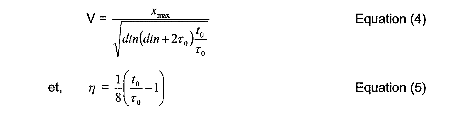
V = Xrnax Equation (4) dtndtn + 2zo ) t- To et, 7] = !( -IJ Equation (5) 8 1'0
La figure 1a représente l'hyperbole anelliptique décalée permettant de réaliser la correction d'obliquité NMO et illustre la signification des paramètres #0 et dtn. In this way, the velocity V and anti-randomness parameters # can be calculated according to equations (2) and (3), using the following conversion equations (4) and (5):
V = Xrnax Equation (4) dtndtn + 2zo) t- To and, 7] =! (-IJ Equation (5) 8 1'0
FIG. 1a represents the shifted antiliptic hyperbole making it possible to carry out the obliquity correction NMO and illustrates the meaning of the parameters # 0 and dtn.
Lesdites coordonnées hyperboliques sont représentées sur cette figure 1. Leur origine sur l'axe des temps est prise à l'intersection dudit axe des temps avec l'asymptote tangente à ladite hyperbole décalée (cf. équation (1 a)) à large offset. Said hyperbolic coordinates are represented in this FIG. 1. Their origin on the time axis is taken at the intersection of said time axis with the asymptote tangent to said offset hyperbola (see equation (1 a)) at large offset.
En utilisant les deux paramètres (dtn, #0), l'équation (1 a) de l'hyperbole anelliptique décalée devient :

t = ta - Tof W + # r-x Equation (6a)
Les paramètres (dtn, #0) définis relativement à la vitesse V à l'anellipticité # permettent ainsi de rendre la correction d'obliquité NMO. Using the two parameters (dtn, # 0), the equation (1 a) of the shifted antiliptic hyperbola becomes:
t = ta - Tof W + # rx Equation (6a)
The parameters (dtn, # 0) defined with respect to the velocity V at the anti-sensitivity # thus make it possible to make the obliquity correction NMO.
CORRNMO = t - to devant être appliquée aux traces de déport x indépendante de to :

CORRNMO(X) = - '0 + zo2 + dtn(dtn i 2zo ) xz Equation (7a)
Il s'agit donc d'une correction d'obliquité statique. Autrement dit, les données enregistrées sur une trace de déport donné seront toutes CORRNMO = t - to be applied to the x offset traces independent of to:
CORRNMO (X) = - '0 + zo2 + dtn (dtn i 2zo) xz Equation (7a)
It is therefore a correction of static obliquity. In other words, the data recorded on a given offset trace will all be
<Desc/Clms Page number 12><Desc / Clms Page number 12>
corrigées de la même manière pour un couple (dtn, #0), indépendamment du temps auquel ces données ont été acquises. Corrected in the same way for a couple (dtn, # 0), regardless of the time at which these data were acquired.
Par conséquent, l'estimation des paramètres de vitesse et d'anellipticité n'est pas perturbée par l'étirement ( stretch selon la terminologie anglo-saxonne) des traces généralement observé lorsque des corrections d'obliquité dynamiques sont réalisées.
![]()
![]()
De manière similaire, en utilisant les deux paramètres (dtn,r0), l'équation (1 b) de la double hyperbole décalée DSQR de la migration PSTM anelliptique devient :

La figure 1 b représente la double hyperbole décalée DSQR de la migration PSTM paramétrée avec les paramètres (dtn, #0). Figure 1b shows the double offset hyperbola DSQR of the PSTM migration parameterized with the parameters (dtn, # 0).
Dans le cadre de la migration PSTM, Xmax représente le maximum de déport et d'ouverture de la migration.
![]()
![]()
15 Les paramètres (dtn,r0) définis relativement à la vitesse V et à l'anellipticité # permettent ainsi de rendre la correction d'obliquité PSTM CORRpSTM = t - to devant être appliquée aux traces de déport x indépendante de to (équation (7b)) :

Il s'agit donc *d une correction PSTM statique. Autrement dit, l'ensemble des échantillons d'ouverture x-xm d'un cube de traces à déport
![]()
constant (cube iso-offset ) est, pour un couple (dtn,) donné, décalé d'un même temps.
![]()
En analysant les paramètres (dtn,r0) en une pluralité de temps de pointé, le procédé selon l'invention permet en particulier de déterminer les
![]()
paramètres (V,j7) nécessaires pour réaliser un traitement comprenant une correction d'obliquité anelliptique des traces d'une collection CMP. It is therefore * a static PSTM correction. In other words, the set of x-xm opening samples of an offset trace cube
![]()
constant (iso-offset cube) is, for a given pair (dtn,) shifted by the same time.
![]()
By analyzing the parameters (dtn, r0) in a plurality of pointing times, the method according to the invention makes it possible in particular to determine the
![]()
parameters (V, j7) necessary to carry out a treatment comprising antiliptic obliquity correction of the traces of a CMP collection.
<Desc/Clms Page number 13> <Desc / Clms Page number 13>
Ledit procédé comporte de manière simplifiée les étapes présentées ci-après. Said method comprises in a simplified manner the steps presented below.
Au cours d'une étape préliminaire, un volume d'analyse comprenant une pluralité de n#uds (dtn, #0) est défini. During a preliminary step, an analysis volume comprising a plurality of nodes (dtn, # 0) is defined.
Puis, pour chacun des noeuds de ce volume, on effectue : # dans un premier temps, selon l'équation (7a), la correction d'obliquité statique des traces de la collection CMP étudiée, en fonction des valeurs des paramètres dtn, #0 au n#ud considéré, ladite correction statique étant valable pour n'importe quel temps du pointé ; # dans un second temps, on calcule la semblance, fonction du temps, associée à la correction réalisée à l'étape précédente. Then, for each of the nodes of this volume, one performs: # in a first time, according to the equation (7a), the static obliquity correction of the traces of the studied CMP collection, according to the values of the parameters dtn, # 0 to the considered node, said static correction being valid for any time of the pointing; # in a second time, we calculate the semblance, a function of time, associated with the correction made in the previous step.
Enfin, pour chaque temps de la pluralité de temps de pointé, on détermine :
![]()
#dans un premier temps, le n#ud (dtn, r0) permettant une correction optimale, par exemple au regard du critère de semblance (un tel critère étant classiquement utilisé en traitement sismique pour mesurer l'horizontalité des courbes de réflexion et déterminer la fiabilité du pointé) ;
![]()
#dans un second temps, on convertit les valeurs des paramètres dtn, r0 audit n#ud de semblance maximale en valeurs des paramètres de vitesse V et d'anellipticité # audit temps de pointé considéré. Finally, for each time of the plurality of pointing times, we determine:
![]()
#in a first time, the node (dtn, r0) allowing an optimal correction, for example with regard to the criterion of similarity (such a criterion being conventionally used in seismic treatment to measure the horizontality of the curves of reflection and to determine the reliability of the pointing);
![]()
#in a second step, we convert the values of the parameters dtn, r0 audit n # ud of maximum similarity into values of the speed parameters V and anellipticity # auditing time considered.
La loi de vitesse (c'est-à-dire l'ensemble des couples (temps du pointé, V)) et la loi d'anellipticité (ensemble des couples (temps du pointé, #)) sont ainsi établies. The law of velocity (that is to say the set of couples (pointing time, V)) and the law of anellipticity (set of couples (pointing time, #)) are thus established.
Finalement la correction d'obliquité de l'ensemble des traces sismiques peut être réalisée en utilisant ces lois de vitesse V et d'anellipticité # dans l'équation (1a) de l'hyperbole anelliptique décalée. Finally, the obliquity correction of all the seismic traces can be carried out by using these velocity V and anellipticity laws # in the equation (1a) of the shifted antiliptic hyperbole.
De manière similaire, et comme cela sera plus particulièrement
![]()
détaillé par la suite, les paramètres (dtn,r0) de la migration PSTM statique (cf. équation (7b)) peuvent également être pointés. Les lois de vitesse V et Similarly, and as it will be more particularly
![]()
detailed below, the parameters (dtn, r0) of the static PSTM migration (see equation (7b)) can also be pointed. The laws of speed V and
<Desc/Clms Page number 14><Desc / Clms Page number 14>
d'anellipticité # sont alors déterminées et peuvent être utilisées, pour réaliser la migration PSTM, dans l'équation (1b) DSQR de la double hyperbole anelliptique décalée. of anellipticity # are then determined and can be used, to perform the PSTM migration, in the equation (1b) DSQR of the double antiliptic double-shift hyperbola.
La figure 2 illustre l'effet du paramètre #0 (et donc, cf. équation (2),
![]()
de l'anellipticité ruz ) sur les résidus de courbure après correction d'obliquité NMO. Figure 2 illustrates the effect of parameter # 0 (and therefore, see equation (2),
![]()
of antilipticity ruz) on the curvature residues after obliquity correction NMO.
On notera que l'échelle verticale temporelle de la courbe de la figure 2 est exagérée afin de bien rendre compte de cet effet. Note that the vertical time scale of the curve of Figure 2 is exaggerated to account for this effect.
Trois courbes sont représentées sur la figure 2 pour lesquelles le paramètre dtn est fixé à la valeur correcte et le paramètre t0 prend différentes valeurs.
La courbe centrale représente le cas où r0 est à sa valeur correcte 7(,j, c'est-à-dire lorsque l'anellipticité 171 correspondante est à sa valeur correcte 17true. Comme cela est attendu, la courbe de réflexion corrigée est alors horizontale.

La courbe supérieure représente le cas où r0 prend une valeur r02 inférieure à sa valeur correcte TO\' l'anellipticité 72 correspondante étant supérieure à sa valeur correcte 17true' La courbe inférieure représente quant à elle le cas où -ro prend une valeur zo3 supérieure à sa valeur correcte 7o,, l'anellipticité 173 étant inférieure à sa valeur correcte 17true'
On remarque de ces courbes inférieure et supérieure que l' horizontalité de la courbe de réflexion corrigée est acceptable à faible
![]()
déport (x 0) et à large déport (x =xmax). The upper curve represents the case where r0 takes a value r02 less than its correct value TO: the corresponding anellipticity 72 being greater than its correct value 17true The lower curve represents the case where -ro takes a higher value zo3 to its correct value 7o ,, the anellipticity 173 being less than its correct value 17true '
It is noted from these lower and upper curves that the horizontality of the corrected reflection curve is acceptable at low
![]()
offset (x 0) and wide offset (x = xmax).
En revanche, on observe des résidus de courbure significatifs lorsque le déport x ne tend pas vers une de ces valeurs limites 0 et Xmax. On note en particulier des résidus particulièrement significatifs pour un déport x centré au milieu de la gamme de déports. On the other hand, significant curvature residues are observed when the offset x does not tend towards one of these limit values 0 and Xmax. In particular, particularly significant residues are noted for an offset x centered in the middle of the range of offsets.
<Desc/Clms Page number 15><Desc / Clms Page number 15>
A titre d'exemple, et comme cela apparaît sur la figure 2, lorsque #

est à ruz, une correction résiduelle RMO r 02 devrait être apportée aux traces de déport XRMO'02 . De manière similaire, lorsque ro est à r03' une correction résiduelle RMOr03 devrait être apportée aux traces de déport x RMO'03 . As an example, and as shown in Figure 2, when #
is in ruz, a residual correction RMO r 02 should be made to the XRMO'02 offset traces. Similarly, when ro is at r03 'a residual correction RMOr03 should be made to the offset traces x RMO'03.
Du fait de ces résidus de courbure significatifs, la gamme des déports peut quasiment être utilisée dans son intégralité afin de déterminer l'anellipticité #. Because of these significant curvature residuals, the range of offsets can almost be used in its entirety to determine the #antilipticity.
Le paramétrage en (dtn, #0) de la correction d'obliquité rend donc possible l'utilisation des données disponibles pour l'ensemble des déports (x compris entre 0 et xmax) dans la détermination de l'anellipticité #. The parameterization (dtn, # 0) of the obliquity correction thus makes it possible to use the available data for all the offsets (x between 0 and xmax) in the determination of the anellipticity #.
Or, comme cela a déjà été évoqué précédemment, cela n'est pas le cas des corrections d'obliquité paramétrées avec V et # pour lesquelles ce sont essentiellement les données à large déport qui permettent l'estimation de l'anellipticité #. However, as has already been mentioned above, this is not the case for obliquity corrections parameterized with V and # for which it is essentially the wide-offset data that allow the estimation of the anellipticity #.
Ainsi, l'effet du nouveau paramètre anelliptique #0 est distribué sur
![]()
tous les déports, au contraire de l'anellipticité 77 qui n'affecte que les larges déports. Le comportement du paramètre #0 permet donc de mieux contraindre les valeurs d'anellipticité. Thus, the effect of the new anelliptic parameter # 0 is distributed on
![]()
all the offsets, unlike the anellipticity 77 which affects only the large offsets. The behavior of the parameter # 0 thus makes it possible to better constrain the values of anellipticity.
Comme cela a -déjà été mentionné précédemment, la détermination des paramètres dtn et ro optimum est réalisée dans un volume d'analyse 3D (to, dtn, #0). As has already been mentioned above, the determination of the optimum dtn and ro parameters is carried out in a 3D analysis volume (to, dtn, # 0).
On considère dans ledit volume d'analyse une pluralité de n#uds
![]()
(dtn, r0), c'est-à-dire une pluralité de couples de paramètres dtn, ro dont les valeurs sont connues. Considered in said analysis volume a plurality of nodes
![]()
(dtn, r0), i.e. a plurality of parameter pairs dtn, ro whose values are known.
Les n#uds sont généralement espacés régulièrement les uns des
![]()
autres, d'un incrément Adtn sur l'axe dtn et d'un incrément Ar0 sur l'axe r0. Nodes are usually spaced regularly from each other.
![]()
others, an increment Adtn on the axis dtn and an increment Ar0 on the axis r0.
<Desc/Clms Page number 16> <Desc / Clms Page number 16>
![]()
Des valeurs minimales dtnmin, romain, tomin et maximales dtnmax. zpomax, tomax des paramètres respectivement dtn, #0 et to permettent de définir les limites dudit volume d'analyse. ![]()
Minimum values dmin, roman, tomin and maximum dtnmax. zpomax, tomax parameters respectively dtn, # 0 and to define the limits of said analysis volume.
De manière avantageuse, des valeurs plausibles des paramètres de vitesse V et d'anellipticité # peuvent être utilisées afin de définir à l'intérieur
![]()
dudit volume d'analyse un corridor [dtnmin(to), dtnmax(to)],Uomin (to), 1-o max(to)]. Advantageously, plausible values of the velocity V and anti-ellipticity parameters can be used in order to define on the inside.
![]()
of said analysis volume a corridor [dtnmin (to), dtnmax (to)], Uomin (to), 1-o max (to)].
Ce corridor permet de restreindre le volume d'analyse et donc le nombre de n#uds (dtn, #0) devant être considéré pour la détermination du couple (dtn, #0) optimal. This corridor makes it possible to restrict the analysis volume and thus the number of nodes (dtn, # 0) to be considered for the determination of the optimal pair (dtn, # 0).
Si l'utilisation dudit corridor est bénéfique pour l'efficacité du procédé selon l'invention, elle permet également de contraindre la solution vers les bons phénomènes, sans avoir à considérer des couples (dtn, #0) (et donc des couples (V, #)) incompatibles, relatifs par exemple à des réflexions multiples ou à divers phénomènes d'interférence. If the use of said corridor is beneficial for the efficiency of the process according to the invention, it also makes it possible to constrain the solution towards the good phenomena, without having to consider pairs (dtn, # 0) (and therefore pairs (V , #)) incompatible, for example relating to multiple reflections or various interference phenomena.
Les figures 3a et 3b représentent ledit volume d'analyse (to, dtn, #0) dans le cadre d'un exemple de traitement de données sismiques réelles lors d'une correction d'obliquité NMO réalisée selon le procédé de l'invention. FIGS. 3a and 3b represent said analysis volume (to, dtn, # 0) in the context of an example of processing of real seismic data during an NMO obliquity correction carried out according to the method of the invention.
La figure 3a représente trois panneaux 2D a, b et c du volume d'analyse : - le panneau 13 est un panneau (dtn, #0) à to constant ; - le panneau b est un panneau (dtn, to ) à #0 constant ;
![]()
- le panneau c est un panneau (r0 , to ) à dtn constant. FIG. 3a shows three 2D panels a, b and c of the analysis volume: the panel 13 is a panel (dtn, # 0) at constant to; the panel b is a constant panel (dtn, to) at # 0;
![]()
the panel c is a panel (r0, to) at constant dtn.
La figure 3b représente de manière schématique le volume d'analyse 3D (to, dtn, #0) ainsi que trois intersections à ce volume selon trois plans à respectivement to, #0, dtn constant, chacune de ces intersections étant projetée sur le panneau a, b ou c correspondant de la figure 3a. FIG. 3b schematically represents the 3D analysis volume (to, dtn, # 0) as well as three intersections at this volume in three planes at respectively to, # 0, constant dtn, each of these intersections being projected onto the panel a, b or c corresponding of Figure 3a.
<Desc/Clms Page number 17> <Desc / Clms Page number 17>
Les panneaux (dtn, #0) à to constant (panneau a dans l'exemple cidessus) sont les panneaux dans lesquels est réalisé le pointé bispectral des paramètres dtn et #0, par exemple selon le critère de semblance maximale de la correction d'obliquité, pour le temps de pointé to considéré.
![]()
![]()
Le corridor [dtnmin(to), dtnmax(to)] [romin (to), o max(t0) mentionné précédemment pour l'analyse effective à l'intérieur du volume d'analyse est également représenté sur la figure 3a (zone plus claire sur chacun des panneaux). The corridor [dtnmin (to), dtnmax (to)] [romin (to), o max (t0) mentioned above for the actual analysis within the analysis volume is also represented in FIG. 3a (zone plus clear on each of the panels).
Le pas d'échantillonnage en temps #t0 des données sismiques définit l'écart entre deux temps de pointé successifs (temps pour lesquels on détermine le n#ud (dtn, #0) de semblance maximale associé) et donc le nombre de panneaux de pointé bispectral devant être considéré. The time sampling step # t0 of the seismic data defines the difference between two successive pointing times (times for which the associated maximum number of n # ud (dtn, # 0) is determined) and therefore the number of panels of pointed bispectral to be considered.
Le pointé automatique permet ainsi d'extraire les paramètres dtn, #0 en une densité d'autant plus importante que l'incrément Ato entre les temps de pointé est faible. The automatic dotting thus makes it possible to extract the parameters dtn, # 0 in a density all the more important that the increment Ato between the pointing times is weak.
L'échantillonnage des paramètres d'analyse dtn et 1'0 est quant à lui directement lié à la résolution de la sismique, dtn et 1'0 ayant effectivement les mêmes dimensions que les enregistrements sismiques. The sampling of the analysis parameters dtn and l0 is directly related to the resolution of the seismic, dtn and 1'0 effectively having the same dimensions as the seismic recordings.
La recherche systématique du maximum de semblance, classiquement connue en soi, permet de déterminer la paire (dtn, #0) procurant, pour un terres de pointé to donné, la meilleure focalisation. The systematic search for maximum semblance, classically known per se, makes it possible to determine the pair (dtn, # 0) providing, for a land from point to point, the best focus.
Des interpolations paraboliques autour des valeurs des n#uds (dtn, #0) peuvent en outre permettre d'évaluer les valeurs des paramètres dtn, #0 entre les différents n#uds effectivement pointés. Et une telle évaluation rend en particulier possible la détermination plus précise encore (par opposition à la détermination limitée aux n#uds du corridor) du couple de
![]()
paramètres dtn, r0 maximisant la fonction de semblance. Parabolic interpolations around the node values (dtn, # 0) can also be used to evaluate the values of the dtn, # 0 parameters between the different nodes actually pointed. And such an assessment makes possible in particular the more precise determination (as opposed to the determination limited to the nodes of the corridor) of the couple of
![]()
dtn, r0 parameters maximizing the semblance function.
<Desc/Clms Page number 18> <Desc / Clms Page number 18>
Finalement les paramètres de vitesse V et d'anellipticité # sont déterminés, toujours pour le temps du pointé to considéré, en utilisant les équations de conversion (4) et (5) susmentionnées. Finally, the velocity parameters V and anellipticity # are determined, again for the time of the point to be considered, using the conversion equations (4) and (5) mentioned above.
La figure 4 permet de comparer les deux approches (V, Van) et (dtn, #0) en représentant, pour un temps de pointé donné, leur panneau de pointé bispectral respectif. FIG. 4 compares the two approaches (V, Van) and (dtn, # 0) by representing, for a given pointing time, their respective bispectral pointing panel.
La figure de droite illustre approche classique (V, Van) pour laquelle les deux axes sont des axes de vitesse (l'anellipticité # étant lié au rapport
![]()
de ces deux vitesses selon 17 = 1 va: -1 ). The figure on the right illustrates the classical approach (V, Van) for which the two axes are velocity axes (the anellipticity # being linked to the ratio
![]()
of these two speeds according to 17 = 1 va: -1).
8 (V4 @)@
La figure de gauche illustre quant à elle l'approche (dtn, # selon l'invention pour laquelle les deux axes sont des axes temporels. 8 (V4 @) @
The figure on the left illustrates the approach (dtn, # according to the invention for which the two axes are time axes.
Il est important de noter de l'étude de cette figure 4 que les paramètres dtn et #0, semblent être décorrélés. Cette décorrélation est frappante lorsque l'on compare les deux approches, l'étalement du spectre (dtn, #0) étant effectivement beaucoup plus réduit que celui du spectre (V, Van). It is important to note from the study of this figure 4 that the parameters dtn and # 0, seem to be decorrelated. This decorrelation is striking when comparing the two approaches, the spread spectrum (dtn, # 0) being effectively much smaller than that of the spectrum (V, Van).
Le pointé réalisé dans le cadre de l'approche (dtn, #0) selon l'invention est donc plus précis que celui classiquement réalisé. The point made in the context of the approach (dtn, # 0) according to the invention is therefore more accurate than that conventionally achieved.
En outre, cette décorrélation permet le filtrage des pointés dtn et
![]()
7-0 séparément, tout efi conservant les corrections d'obliquité. Cela n'est pas le cas pour les paramètres V et # pour lesquels la diminution de l'un des paramètres doit impérativement être compensée par l'augmentation de l'autre, et vice versa. In addition, this decorrelation allows filtering dtn dtn and
![]()
7-0 separately, while retaining skew corrections. This is not the case for the parameters V and # for which the decrease of one of the parameters must imperatively be compensated by the increase of the other, and vice versa.
Et grâce aux interpolations et filtrages individuels des paramètres de l'invention, dtn et #0, il est alors possible de réaliser l'interpolation et le filtrage simultanés des paramètres standards V et # de correction d'obliquité. And thanks to the interpolations and individual filtering of the parameters of the invention, dtn and # 0, it is then possible to carry out the simultaneous interpolation and filtering of the standard parameters V and obliquity correction #.
<Desc/Clms Page number 19> <Desc / Clms Page number 19>
La figure 5 représente la correspondance non linéaire, selon les équations (4) et (5) présentées ci-dessus, entre la paire de paramètres temporels (dtn, #0) et la paire de paramètre de vitesse (V, Van). Figure 5 shows the nonlinear correspondence, according to equations (4) and (5) presented above, between the pair of time parameters (dtn, # 0) and the speed parameter pair (V, Van).
La figure 6 représente de gauche à droite : - une collection CMP de traces sismiques réelles avant correction d'obliquité ; - le pointé du paramètre dtn correspondant à cette collection de traces ; - le pointé du paramètre #0 correspondant à cette collection de traces.

Sur le pointé du paramètre r, à droite sur la figure 6, la ligne droite ro = t0 correspond aux courbes de réflexion purement hyperboliques. On the point of the parameter r, on the right in FIG. 6, the straight line ro = t0 corresponds to purely hyperbolic reflection curves.
La figure 7 représente quant à elle, de droite à gauche, la fonction de semblance et les fonctions de vitesse V et d'anellipticité # déduites (cf.
![]()
équations (4) et (5)) du pointé des paramètres dtn et r0 représenté sur la figure 6. Figure 7 represents, from right to left, the function of semblance and the functions of speed V and anellipticity # deduced (cf.
![]()
equations (4) and (5)) of the dtn and r0 parameters shown in FIG.
On note, sur cet exemple de traitement de données sismiques réelles, que les valeurs de V, # obtenues correspondent pour la plupart à une semblance supérieure à 40%. It is noted on this example of actual seismic data processing, that the values of V, # obtained correspond for the most part to a semblance greater than 40%.
La description ci-après détaille deux modes de réalisation particuliers de l'invention. The description below details two particular embodiments of the invention.
Le premier de ces modes concerne un procédé de détermination des paramètres optimum pour réaliser une correction d'obliquité NMO anelliptique des traces d'une collection CMP (voir les différentes étapes représentées sur l'organigramme de la figure 8a). The first of these modes relates to a method for determining the optimum parameters for performing an anelliptic NMO obliquity correction of the traces of a CMP collection (see the various steps represented on the flowchart of FIG. 8a).
En référence à la figure 8a, ce premier mode de réalisation comprend une étape 1a d'initialisation au cours de laquelle sont réalisées successivement les opérations de :

#détermination des limites du volume d'analyse [dtnmin, dtn,aj,[-ro min, zo maxj,[tOmin, toman ; With reference to FIG. 8a, this first embodiment comprises an initialization step 1a during which the operations of:
# determination of the limits of the analysis volume [dtnmin, dtn, aj, [- ro min, zo maxj, [tOmin, toman;
<Desc/Clms Page number 20><Desc / Clms Page number 20>
# calcul des corrections d'obliquité CORRNMO (équation (7a)) pour tous les déports et pour tous les n#uds (dtn, #0) inclus dans le volume d'analyse ;
![]()
#délimitation à l'intérieur du volume d'analyse du corridor [dtnm;(to), dtnmax(to)] [1'0 min(to), Zo max(to)] des valeurs plausibles de vitesse et d'anellipticité ; Une fois cette étape 1a d'initialisation réalisée, une étape 2a de
![]()
calcul des lois de vitesse V(to) et d'anellipticité t7(to) est mise en oeuvre pour chaque collection de traces CMP.
Cette étape 2a comprend :
![]()
#une première opération 3a réalisée pour chaque n#ud (dtn, 1'0) du corridor défini lors de l'étape 1a d'initialisation, au cours de laquelle sont réalisées successivement, pour chaque temps du pointé to, les opérations de : - application pour tous les déport, le long du corridor, des corrections CORRNMO d'obliquité statiques pré-calculées lors de l'étape 1a d'initialisation ; - calcul de la fonction de semblance sur les données corrigées le long du corridor en utilisant une fenêtre temporelle appropriée à l'ondelette dominante ; - sommation (calcul du stack ) des données corrigées le
![]()
long duo( corridor (seules les données à faibles déports pouvant avantageusement être pour cela utilisées) ; # une seconde opération 4a réalisée pour chaque temps to du pointé
![]()
(lesdits temps étant espacés de Ato entre [tomin, torana), au cours de laquelle sont réalisées les opérations de : - recherche du maximum de semblance dans le corridor

[dtnmin(to), dtnmax(to)],[romin(to), o max(t0) du panneau bispectral (dtn, 1'0) ; # calculation of CORRNMO obliquity corrections (equation (7a)) for all offsets and for all nodes (dtn, # 0) included in the analysis volume;
![]()
# delineation within the analysis volume of the corridor [dtnm; (to), dtnmax (to)] [1'0 min (to), Zo max (to)] plausible values of velocity and anellipticity; Once this initialization step 1a has been completed, a step 2a of
![]()
computation of the laws of speed V (to) and of anellipticity t7 (to) is implemented for each collection of traces CMP.
This step 2a comprises:
![]()
#a first operation 3a carried out for each node (dtn, 1'0) of the corridor defined during the initialization step 1a, during which are carried out successively, for each time of the point to, the operations of: - Application for all the offsets, along the corridor, CORRNMO corrections of static obliquity pre-calculated during the initialization step 1a; calculating the semblance function on the corrected data along the corridor using a time window appropriate to the dominant wavelet; - summation (calculation of the stack) of the data corrected on
![]()
long duo (corridor (only data with low offsets can advantageously be used for this purpose); # a second operation 4a performed for each time to the pointed
![]()
(said times being spaced from Ato between [tomin, torana], during which are carried out the operations of: - search of the maximum of semblance in the corridor
[dtnmin (to), dtnmax (to)], [romin (to), o max (t0) of the bispectral panel (dtn, 1'0);
<Desc/Clms Page number 21><Desc / Clms Page number 21>
contrôle du fait que la position en (dtn, #0) du maximum de semblance correspond à un extremum de la sommation pour
![]()
les mêmes valeurs dtn et r0 ; création des séries dtn(to), #0 (to) et semblance (to) ; # une troisième opération 5a visant à sélectionner et ajuster les pointés obtenus, au cours de laquelle sont réalisées les opérations de : - tri croissant de la série semblance(to) ; - validation des pointés dtn et #0 pour lesquels la distance en temps aux pointés de semblance plus élevé est supérieure à une valeur prédéfinie ; - ajustement des valeurs dtn et #0 pointées et validées par des interpolations paraboliques utilisant des valeurs alentours ; - rétention des valeurs pointées, validées et ajustées si le calcul des vitesses d'intervalle de Dix avec les pointés de semblance plus élevée est possible. check that the position in (dtn, # 0) of the maximum of semblance corresponds to an extremum of the summation for
![]()
the same values dtn and r0; creation of series dtn (to), # 0 (to) and semblance (to); # a third operation 5a for selecting and adjusting the obtained dots, during which are performed the operations of: - growing sort of the series semblance (to); - Validation of points dtn and # 0 for which the distance in time at the points of higher similarity is greater than a predefined value; - adjustment of the values dtn and # 0 pointed and validated by parabolic interpolations using surrounding values; - retention of dotted, validated and adjusted values if the calculation of the interval velocities of Ten with the highest possible dots is possible.
# une quatrième opération 6a visant à convertir, à l'aide des équations (3) et (4), les valeurs de dtn et #0 pointées, validées, ajustées et retenues au cours de l'opération 5a en lois de vitesse V et d'anellipticité #. a fourth operation 6a for converting, using the equations (3) and (4), the values of dtn and # 0 pointed, validated, adjusted and retained during the operation 5a in speed laws V and of anellipticity #.
Les lois fonctions du temps de la vitesse V et de l'anellipticité # sont ainsi parfaitement déterminées. Et la correction d'obliquité NMO anelliptique des traces sismiques de la collection CMP peut ainsi être précisément réalisée. The laws which are functions of the time of the velocity V and of the anellipticity # are thus perfectly determined. And the anelliptic NMO obliquity correction of the seismic traces of the CMP collection can thus be precisely carried out.
Le second mode de réalisation particulier de l'invention concerne un procédé de détermination des paramètres optimum pour la migration PSTM anelliptique des traces d'une collection CMP. The second particular embodiment of the invention relates to a method for determining the optimum parameters for the anelliptic PSTM migration of traces of a CMP collection.
Ce second mode de réalisation peut être compris comme une généralisation du premier mode discuté ci-dessus. This second embodiment can be understood as a generalization of the first mode discussed above.
<Desc/Clms Page number 22> <Desc / Clms Page number 22>
En effet, comme cela a été montré précédemment, l'utilisation des paramètres (dtn, #0) permet des corrections d'obliquité PSTM statiques (cf. équation (7b)). Indeed, as was shown previously, the use of the parameters (dtn, # 0) allows static PSTM obliquity corrections (see equation (7b)).
Cette utilisation présente, dans le cadre de la correction d'obliquité PSTM, les mêmes avantages que ceux précédemment discutés pour la correction d'obliquité NMO. This use presents, in the context of the PSTM obliquity correction, the same advantages as those previously discussed for the NMO obliquity correction.
Plus précisément, on notera que le premier mode de réalisation n'est qu'un cas particulier du second mode de réalisation correspondant au cas d'une ouverture de migration nulle. More precisely, it will be noted that the first embodiment is only a particular case of the second embodiment corresponding to the case of a zero migration opening.
En référence à la figure 8b, ledit second mode de réalisation comprend une étape 1 b d'initialisation au cours de laquelle sont réalisées successivement les opérations de :

#détermination des limites du volume d'analyse[dtnmin, dtnmax],[r0 min, To ma7[tOmin, tomax] #calcul des corrections d'obliquité CORRpsTm (équation (7b)) pour tous les noeuds (dtn, #0) inclus dans le volume d'analyse et pour tous les déports de migration à l'intérieur de l'ouverture de migration ;

#délimitation à l'intérieur du volume d'analyse du corridor [dtnm;n(to}, dtnmax(to)],[ T 0 min(to), T 0 max(to)] des valeurs plausibles de vitesses et d'anellipticité ;
Une fois cette étape 1 b d'initialisation réalisée, ledit premier mode de réalisation met en #uvre, pour chaque collection de traces CMP, une étape 2b de calcul des lois de vitesse V(to) et d'anellipticité #(t0). With reference to FIG. 8b, said second embodiment comprises an initialization step 1b in which the operations of:
# determination of the limits of the analysis volume [dtnmin, dtnmax], [r0 min, To ma7 [tOmin, tomax] #calculus of obliquity corrections CORRpsTm (equation (7b)) for all the nodes (dtn, # 0) included in the analysis volume and for all migration offsets within the migration opening;
# delineation within the corridor analysis volume [dtnm; n (to}, dtnmax (to)], [T 0 min (to), T 0 max (to)] of plausible values of velocities and anellipticity;
Once this initialization step 1b has been carried out, said first embodiment implements, for each collection of traces CMP, a step 2b for calculating the speed laws V (to) and anellipticity # (t0).
Cette étape 2b comprend : # une première opération 3b réalisée pour chaque n#ud (dtn, #0) du corridor défini lors de l'étape 1a d'initialisation, au cours de laquelle sont réalisées successivement : o pour chaque classe de déport, les opérations de : This step 2b comprises: # a first operation 3b carried out for each node # (dtn, # 0) of the corridor defined during the initialization step 1a, during which are successively carried out: o for each class of offset, the operations of:
<Desc/Clms Page number 23><Desc / Clms Page number 23>
# application sur tous les points milieu à l'intérieur de l'ouverture de la migration, le long du corridor, s corrections CORRPSTM statiques pré-calculées lors de l'étape 1 b d'initialisation ; # sommation des points milieu corrigés le long du corridor ; o pour chaque temps du pointé to, les opérations de : # calcul de la fonction de semblance sur les données corrigées le long du corridor en utilisant une fenêtre temporelle appropriée à l'ondelette dominante ; # sommation (calcul du stack ) des données corrigées le long du corridor (seules les données à faibles déports pouvant avantageusement être pour cela utilisées) ; # une seconde opération 4b réalisée pour chaque temps to du pointé, similaire à l'opération 4a décrite précédemment, visant à créer les séries dtn(to), #0(t0) et semblance (to) ; # une troisième opération 5b, similaire à l'opération 5a décrite précédemment, visant à sélectionner et ajuster les pointés obtenus. # application on all the middle points inside the opening of the migration, along the corridor, s static CORRPSTM corrections pre-calculated during the initialization step 1b; # summation of corrected midpoints along the corridor; o for each time from the point to, the operations of: # calculation of the semblance function on the corrected data along the corridor using a time window appropriate to the dominant wavelet; # summation (calculation of the stack) of the corrected data along the corridor (only data with low offsets can advantageously be used for this purpose); # a second operation 4b performed for each time to the dotted, similar to the operation 4a described above, to create series dtn (to), # 0 (t0) and semblance (to); # a third operation 5b, similar to the operation 5a described above, for selecting and adjusting the dots obtained.
# une quatrième opération 6b, similaire à l'opération 5a décrite précédemment,visant à convertir les valeurs de dtn et #0 en lois de
![]()
vitesse V et d'an4ipticité t7. a fourth operation 6b, similar to the operation 5a described above, for converting the values of dtn and # 0 into laws of
![]()
speed V and an4ipticity t7.
Les lois fonctions du temps de la vitesse V et de l'anellipticité # sont ainsi parfaitement déterminées. Et la migration PSTM des traces sismiques de la collection CMP peut ainsi être précisément réalisée. The laws which are functions of the time of the velocity V and of the anellipticity # are thus perfectly determined. And the PSTM migration of the seismic traces of the CMP collection can be precisely realized.
La figure 9 illustre le second mode de réalisation de l'invention dont il vient d'être fait état. FIG. 9 illustrates the second embodiment of the invention of which it has just been mentioned.
Les données sismiques sont initialement regroupées en cubes à déport constant (cube iso-déport ou iso-offset ). The seismic data are initially grouped in cubes with constant offset (iso-offset cube or iso-offset).
Comme cela vient d'être présenté, les corrections d'obliquité CORRPSTM sont appliquées (cf. première opération de l'étape 3b), pour As has just been presented, CORRPSTM obliquity corrections are applied (see first step of step 3b), for
<Desc/Clms Page number 24><Desc / Clms Page number 24>
chaque classe de déport (soit pour chaque cube iso-déport), sur tous les points milieu. La flèche libellée MIG sur la figure 9 illustre cette opération. each offset class (for each iso-offset cube), on all midpoints. The arrow labeled MIG in Figure 9 illustrates this operation.
Les points milieux ainsi corrigés sont ensuite sommés au cours de la seconde opération de l'étape 3b, la flèche libellée STACK sur la figure 9 illustrant cette opération. The corrected midpoints are then summed during the second operation of step 3b, the arrow labeled STACK in FIG. 9 illustrating this operation.
Ces deux opérations MIG et STACK sont spécifiques au second mode de réalisation de l'invention (migration PSTM). These two operations MIG and STACK are specific to the second embodiment of the invention (PSTM migration).
Les opérations suivantes sont en revanche mises en #uvre dans le cadre de chacun des deux modes de réalisation discutés (la correction d'obliquité NMO correspondant, comme on l'a vu, au cas particulier de la migration PSTM d'ouverture de migration nulle). The following operations, on the other hand, are implemented in the context of each of the two embodiments discussed (the corresponding NMO obliquity correction, as we have seen, in the particular case of the zero migration opening PSTM migration). ).
Pour chaque temps du pointé, la semblance est ensuite calculée (seconde opération de l'étape 3a pour la seule correction d'obliquité, troisième opération de l'étape 3b pour la migration PSTM), la flèche libellée 'semblance' sur la figure 9 illustrant cette opération. For each time of the pointing, the similarity is then calculated (second operation of step 3a for the only obliquity correction, third operation of step 3b for the PSTM migration), the arrow labeled 'semblance' in FIG. 9 illustrating this operation.
Bien entendu, les opération MIG, STACK et de calcul de la semblance sont mises en #uvre pour chaque n#ud (dtn,#0). Of course, the operations MIG, STACK and computation of the semblance are implemented for each node # (dtn, # 0).
Le 'pointé bispectral automatique' mentionné sur la figure 9 correspond au pointé des paramètres (dtn,#0) de semblance maximale pour chaque temps to du pointé (opérations 4a, 4b sur les figures respectivement 8a, 8b). La flèche libellée MAX illustre la recherche du maximum de semblance. The 'automatic bispectral dash' mentioned in FIG. 9 corresponds to the maximum appearances (dtn, # 0) of the maximum appearance for each time to the dotted point (operations 4a, 4b in FIGS. 8a, 8b respectively). The arrow labeled MAX illustrates the search for maximum likeness.
Finalement les pointés des paramètres (dtn,#0) pointés sont convertis en lois de vitesse V et d'anellipticité # (opération 6a, 6b sur les figures 8a, 8b et flèche libellée CONV sur la figure 9). Finally, the dots of the pointed parameters (dtn, # 0) are converted into speed laws V and anellipticity # (operation 6a, 6b in FIGS. 8a, 8b and arrow labeled CONV in FIG. 9).
Claims (24)


Priority Applications (8)
| Application Number | Priority Date | Filing Date | Title |
|---|---|---|---|
| FR0308861A FR2858064B1 (en) | 2003-07-21 | 2003-07-21 | BISPECTRAL TIP METHOD OF ANTIFIPTIC OBLIQUITY CORRECTION PARAMETERS |
| PCT/IB2004/002617 WO2005008291A1 (en) | 2003-07-21 | 2004-07-20 | Method for bispectral picking of anelliptical nmo correction parameters |
| US10/565,405 US7889599B2 (en) | 2003-07-21 | 2004-07-20 | Method for bispectral picking of anelliptical NMO correction parameters |
| CA2533011A CA2533011C (en) | 2003-07-21 | 2004-07-20 | Method for bispectral picking of anelliptical nmo correction parameters |
| GB0602677A GB2420626B (en) | 2003-07-21 | 2004-07-20 | Method for bispectral picking of anelliptical nmo correction parameters |
| MYPI20042928A MY139828A (en) | 2003-07-21 | 2004-07-21 | Method for bispectral picking of anelliptical nmo correction parameters |
| NO20060848A NO336540B1 (en) | 2003-07-21 | 2006-02-21 | Method for bispectral picking of anelliptical NMO correction parameters |
| US13/011,035 US8139441B2 (en) | 2003-07-21 | 2011-01-21 | Method for bispectral picking of anelliptical NMO correction parameters |
Applications Claiming Priority (1)
| Application Number | Priority Date | Filing Date | Title |
|---|---|---|---|
| FR0308861A FR2858064B1 (en) | 2003-07-21 | 2003-07-21 | BISPECTRAL TIP METHOD OF ANTIFIPTIC OBLIQUITY CORRECTION PARAMETERS |
Publications (2)
| Publication Number | Publication Date |
|---|---|
| FR2858064A1 true FR2858064A1 (en) | 2005-01-28 |
| FR2858064B1 FR2858064B1 (en) | 2005-09-16 |
Family
ID=33560959
Family Applications (1)
| Application Number | Title | Priority Date | Filing Date |
|---|---|---|---|
| FR0308861A Expired - Fee Related FR2858064B1 (en) | 2003-07-21 | 2003-07-21 | BISPECTRAL TIP METHOD OF ANTIFIPTIC OBLIQUITY CORRECTION PARAMETERS |
Country Status (7)
| Country | Link |
|---|---|
| US (2) | US7889599B2 (en) |
| CA (1) | CA2533011C (en) |
| FR (1) | FR2858064B1 (en) |
| GB (1) | GB2420626B (en) |
| MY (1) | MY139828A (en) |
| NO (1) | NO336540B1 (en) |
| WO (1) | WO2005008291A1 (en) |
Cited By (3)
| Publication number | Priority date | Publication date | Assignee | Title |
|---|---|---|---|---|
| CN103605158A (en) * | 2013-10-30 | 2014-02-26 | 中国石油天然气集团公司 | Determination method and device for maximum geophone offset |
| CN107085236A (en) * | 2017-03-23 | 2017-08-22 | 中国石油天然气集团公司 | The determination method and apparatus of maximum offset |
| FR3057962A1 (en) * | 2016-10-25 | 2018-04-27 | Landmark Graphics Corporation | ESTIMATION OF THE INTERVAL ANISOTROPIC PARAMETER FOR DEPTH MIGRATION BEFORE SUMMING USING A LESS SQUARE METHOD |
Families Citing this family (5)
| Publication number | Priority date | Publication date | Assignee | Title |
|---|---|---|---|---|
| US7924652B2 (en) * | 2007-06-01 | 2011-04-12 | Baker Hughes Incorporated | Method for determining seismic anisotropy |
| CN102478666B (en) * | 2010-11-23 | 2013-11-13 | 中国石油天然气集团公司 | Method for increasing controllable focus seismographic record first arrival picking precision |
| CN104834009B (en) * | 2014-12-02 | 2019-01-11 | 夏正元 | A kind of hyperbolic velocity scanning and the method for dynamic correction |
| RU2573620C1 (en) * | 2014-10-03 | 2016-01-20 | Шлюмберже Текнолоджи Б.В. | Method of determining acoustic wave velocity in porous medium |
| US11467305B2 (en) * | 2017-06-09 | 2022-10-11 | Baker Hughes, A Ge Company, Llc | Anisotropic NMO correction and its application to attenuate noises in VSP data |
Citations (1)
| Publication number | Priority date | Publication date | Assignee | Title |
|---|---|---|---|---|
| US6094400A (en) * | 1996-04-15 | 2000-07-25 | Schlumberger Technology Corporation | Inversion method for seismic data |
Family Cites Families (5)
| Publication number | Priority date | Publication date | Assignee | Title |
|---|---|---|---|---|
| GB9727417D0 (en) * | 1997-12-30 | 1998-02-25 | Geco As | A method of analyzing pre-stack seismic data |
| US6128580A (en) * | 1998-04-17 | 2000-10-03 | Bp Amoco Corporation | Converted-wave processing in many-layered anisotropic media |
| US6502038B1 (en) * | 2000-06-30 | 2002-12-31 | Exxonmobil Upstream Research Company | Method for non-hyperbolic moveout analysis of seismic data |
| US6681184B2 (en) * | 2001-05-15 | 2004-01-20 | Input/Output, Inc. | System for estimating azimuthal variations in seismic data |
| US6864890B2 (en) * | 2002-08-27 | 2005-03-08 | Comoco Phillips Company | Method of building and updating an anisotropic velocity model for depth imaging of seismic data |
-
2003
- 2003-07-21 FR FR0308861A patent/FR2858064B1/en not_active Expired - Fee Related
-
2004
- 2004-07-20 US US10/565,405 patent/US7889599B2/en not_active Expired - Fee Related
- 2004-07-20 WO PCT/IB2004/002617 patent/WO2005008291A1/en active Application Filing
- 2004-07-20 GB GB0602677A patent/GB2420626B/en not_active Expired - Fee Related
- 2004-07-20 CA CA2533011A patent/CA2533011C/en not_active Expired - Fee Related
- 2004-07-21 MY MYPI20042928A patent/MY139828A/en unknown
-
2006
- 2006-02-21 NO NO20060848A patent/NO336540B1/en not_active IP Right Cessation
-
2011
- 2011-01-21 US US13/011,035 patent/US8139441B2/en not_active Expired - Fee Related
Patent Citations (1)
| Publication number | Priority date | Publication date | Assignee | Title |
|---|---|---|---|---|
| US6094400A (en) * | 1996-04-15 | 2000-07-25 | Schlumberger Technology Corporation | Inversion method for seismic data |
Non-Patent Citations (2)
| Title |
|---|
| SAYERS C.M.: "Simplified anisotropy parameters for transversely isotropic sedimentary rocks", GEOPHYSICS, SOCIETY OF EXPLORATION GEOPHYSICISTS. TULSA,US,, vol. 60, no. 6, 1 November 1995 (1995-11-01) - 12 December 1995 (1995-12-12), pages 1933 - 1935, XP002275803 * |
| TSVANKIN I AND TSVANKIN I: "velocity analysis for transversely isotropic media", GEOPHYSICS, SOCIETY OF EXPLORATION GEOPHYSICISTS. TULSA, US, vol. 60, no. 5, 1 September 1995 (1995-09-01), pages 1550 - 1566, XP002082651, ISSN: 0016-8033 * |
Cited By (4)
| Publication number | Priority date | Publication date | Assignee | Title |
|---|---|---|---|---|
| CN103605158A (en) * | 2013-10-30 | 2014-02-26 | 中国石油天然气集团公司 | Determination method and device for maximum geophone offset |
| CN103605158B (en) * | 2013-10-30 | 2016-04-06 | 中国石油天然气集团公司 | A kind of maximum offset defining method and device |
| FR3057962A1 (en) * | 2016-10-25 | 2018-04-27 | Landmark Graphics Corporation | ESTIMATION OF THE INTERVAL ANISOTROPIC PARAMETER FOR DEPTH MIGRATION BEFORE SUMMING USING A LESS SQUARE METHOD |
| CN107085236A (en) * | 2017-03-23 | 2017-08-22 | 中国石油天然气集团公司 | The determination method and apparatus of maximum offset |
Also Published As
| Publication number | Publication date |
|---|---|
| WO2005008291A1 (en) | 2005-01-27 |
| MY139828A (en) | 2009-10-30 |
| GB2420626B (en) | 2007-11-21 |
| GB2420626A (en) | 2006-05-31 |
| FR2858064B1 (en) | 2005-09-16 |
| GB0602677D0 (en) | 2006-03-22 |
| US20110292765A1 (en) | 2011-12-01 |
| NO336540B1 (en) | 2015-09-21 |
| CA2533011A1 (en) | 2005-01-27 |
| US20060291330A1 (en) | 2006-12-28 |
| CA2533011C (en) | 2014-07-15 |
| NO20060848L (en) | 2006-02-21 |
| US8139441B2 (en) | 2012-03-20 |
| US7889599B2 (en) | 2011-02-15 |
Similar Documents
| Publication | Publication Date | Title |
|---|---|---|
| EP0789849B1 (en) | Method for representing the path of one or more boreholes in a spatial and temporal domain | |
| EP0889331B1 (en) | Method for 3D modelling of the impedance of a heterogeneous volume of the subsurface | |
| FR2821677A1 (en) | Tomographic inversion of checked events on seismic migrated data uses depth migration before addition of seismic data is determined for a number of field speeds | |
| EP0354112A1 (en) | Method for obtaining a model representative of a heterogeneous medium, in particular of the sub-soil | |
| FR2873823A1 (en) | METHOD FOR CONSTRUCTING A MODEL OF A HETEROGENEOUS ENVIRONMENT DESCRIBED BY MULTIPLE PARAMETERS FROM DATA EXPRESSED IN DIFFERENT TIME SCALES | |
| CN110780351B (en) | Longitudinal wave and converted wave prestack joint inversion method and system | |
| FR2916859A1 (en) | METHOD OF PROCESSING SEISMIC DATA | |
| EP0797780B1 (en) | Method for processing reflection seismic traces recorded for variable offsets | |
| FR2858063A1 (en) | Method of estimating the rates of coverage of seismic illumination in 3D in the migration field | |
| FR2616920A1 (en) | INVERSION OF A VERTICAL SEISMIC PROFILE BY MINIMIZING A FUNCTION OF THE ENTROPY TYPE | |
| NO336540B1 (en) | Method for bispectral picking of anelliptical NMO correction parameters | |
| CA2195497C (en) | Arine seismic exploration procedure using a pair of hydrophone and geophone sensors | |
| FR2735244A1 (en) | PROCESSING METHOD FOR OBTAINING SUMMARY ZERO-SEPARATION SEISMIC DATA IN THE DEEP AREA | |
| FR2792080A1 (en) | METHODS OF PROCESSING SEISMIC WAVE FIELDS, COMPENSATING THE EFFECT OF IRREGULAR ILLUMINATION OF SUBTERRANEAN REFLECTORS, ANALYZING ILLUMINATION CHARACTERS, AND SEISMIC DATA FILTERING | |
| CA2464799C (en) | Method of determining a model for seismic wave velocity in a heterogeneous subsurface formation | |
| EP0698220B1 (en) | Method for modelling kinematic seismic data processed with at least one motion operator | |
| FR2884619A1 (en) | METHOD FOR PROCESSING SEISMIC DATA FOR REALIZING AN RMO POINT | |
| FR2755243A1 (en) | ADVANCED PRE-SUM MIGRATION METHOD | |
| FR2801387A1 (en) | Processing seismic data, when prospecting for oil or gas, comprises identifying maxima in energy matrix lying along path in space produced by parabolic Radon transformation, calculating energy matrix along selected path through Radon space | |
| EP0610123B1 (en) | Process for improving the estimated seismic propagation velocity by focussing analysis | |
| WO1992018883A1 (en) | Processing method for obtaining a zero-offset sum section | |
| EP0412013B1 (en) | Method of treating seismic reflection data to obtain seismic cross-sections | |
| FR2879306A1 (en) | METHOD FOR CORRECTING TREATMENT OF SEISMIC TRACES | |
| EP0888562A1 (en) | Physical attribute migration method for a medium | |
| Winthaegen et al. | Using the CFP-methodology for PP and PS angle dependent reflectivity analysis |
Legal Events
| Date | Code | Title | Description |
|---|---|---|---|
| CA | Change of address | ||
| CD | Change of name or company name | ||
| TP | Transmission of property | ||
| PLFP | Fee payment |
Year of fee payment: 14 |
|
| ST | Notification of lapse |