FR2760741A1 - METHOD OF DENSIFICATION OF A POROUS STRUCTURE INVOLVING AN ORIGINAL PRECURSOR AND ASSOCIATED DEVICE - Google Patents
METHOD OF DENSIFICATION OF A POROUS STRUCTURE INVOLVING AN ORIGINAL PRECURSOR AND ASSOCIATED DEVICE Download PDFInfo
- Publication number
- FR2760741A1 FR2760741A1 FR9702986A FR9702986A FR2760741A1 FR 2760741 A1 FR2760741 A1 FR 2760741A1 FR 9702986 A FR9702986 A FR 9702986A FR 9702986 A FR9702986 A FR 9702986A FR 2760741 A1 FR2760741 A1 FR 2760741A1
- Authority
- FR
- France
- Prior art keywords
- porous structure
- heating
- hydrocarbon
- resistor
- densified
- Prior art date
- Legal status (The legal status is an assumption and is not a legal conclusion. Google has not performed a legal analysis and makes no representation as to the accuracy of the status listed.)
- Granted
Links
Classifications
-
- C—CHEMISTRY; METALLURGY
- C04—CEMENTS; CONCRETE; ARTIFICIAL STONE; CERAMICS; REFRACTORIES
- C04B—LIME, MAGNESIA; SLAG; CEMENTS; COMPOSITIONS THEREOF, e.g. MORTARS, CONCRETE OR LIKE BUILDING MATERIALS; ARTIFICIAL STONE; CERAMICS; REFRACTORIES; TREATMENT OF NATURAL STONE
- C04B41/00—After-treatment of mortars, concrete, artificial stone or ceramics; Treatment of natural stone
- C04B41/009—After-treatment of mortars, concrete, artificial stone or ceramics; Treatment of natural stone characterised by the material treated
-
- C—CHEMISTRY; METALLURGY
- C04—CEMENTS; CONCRETE; ARTIFICIAL STONE; CERAMICS; REFRACTORIES
- C04B—LIME, MAGNESIA; SLAG; CEMENTS; COMPOSITIONS THEREOF, e.g. MORTARS, CONCRETE OR LIKE BUILDING MATERIALS; ARTIFICIAL STONE; CERAMICS; REFRACTORIES; TREATMENT OF NATURAL STONE
- C04B35/00—Shaped ceramic products characterised by their composition; Ceramics compositions; Processing powders of inorganic compounds preparatory to the manufacturing of ceramic products
- C04B35/71—Ceramic products containing macroscopic reinforcing agents
- C04B35/78—Ceramic products containing macroscopic reinforcing agents containing non-metallic materials
- C04B35/80—Fibres, filaments, whiskers, platelets, or the like
- C04B35/83—Carbon fibres in a carbon matrix
-
- C—CHEMISTRY; METALLURGY
- C04—CEMENTS; CONCRETE; ARTIFICIAL STONE; CERAMICS; REFRACTORIES
- C04B—LIME, MAGNESIA; SLAG; CEMENTS; COMPOSITIONS THEREOF, e.g. MORTARS, CONCRETE OR LIKE BUILDING MATERIALS; ARTIFICIAL STONE; CERAMICS; REFRACTORIES; TREATMENT OF NATURAL STONE
- C04B41/00—After-treatment of mortars, concrete, artificial stone or ceramics; Treatment of natural stone
- C04B41/45—Coating or impregnating, e.g. injection in masonry, partial coating of green or fired ceramics, organic coating compositions for adhering together two concrete elements
- C04B41/50—Coating or impregnating, e.g. injection in masonry, partial coating of green or fired ceramics, organic coating compositions for adhering together two concrete elements with inorganic materials
- C04B41/5001—Coating or impregnating, e.g. injection in masonry, partial coating of green or fired ceramics, organic coating compositions for adhering together two concrete elements with inorganic materials with carbon or carbonisable materials
-
- C—CHEMISTRY; METALLURGY
- C04—CEMENTS; CONCRETE; ARTIFICIAL STONE; CERAMICS; REFRACTORIES
- C04B—LIME, MAGNESIA; SLAG; CEMENTS; COMPOSITIONS THEREOF, e.g. MORTARS, CONCRETE OR LIKE BUILDING MATERIALS; ARTIFICIAL STONE; CERAMICS; REFRACTORIES; TREATMENT OF NATURAL STONE
- C04B41/00—After-treatment of mortars, concrete, artificial stone or ceramics; Treatment of natural stone
- C04B41/80—After-treatment of mortars, concrete, artificial stone or ceramics; Treatment of natural stone of only ceramics
- C04B41/81—Coating or impregnation
- C04B41/85—Coating or impregnation with inorganic materials
-
- C—CHEMISTRY; METALLURGY
- C23—COATING METALLIC MATERIAL; COATING MATERIAL WITH METALLIC MATERIAL; CHEMICAL SURFACE TREATMENT; DIFFUSION TREATMENT OF METALLIC MATERIAL; COATING BY VACUUM EVAPORATION, BY SPUTTERING, BY ION IMPLANTATION OR BY CHEMICAL VAPOUR DEPOSITION, IN GENERAL; INHIBITING CORROSION OF METALLIC MATERIAL OR INCRUSTATION IN GENERAL
- C23C—COATING METALLIC MATERIAL; COATING MATERIAL WITH METALLIC MATERIAL; SURFACE TREATMENT OF METALLIC MATERIAL BY DIFFUSION INTO THE SURFACE, BY CHEMICAL CONVERSION OR SUBSTITUTION; COATING BY VACUUM EVAPORATION, BY SPUTTERING, BY ION IMPLANTATION OR BY CHEMICAL VAPOUR DEPOSITION, IN GENERAL
- C23C16/00—Chemical coating by decomposition of gaseous compounds, without leaving reaction products of surface material in the coating, i.e. chemical vapour deposition [CVD] processes
- C23C16/04—Coating on selected surface areas, e.g. using masks
- C23C16/045—Coating cavities or hollow spaces, e.g. interior of tubes; Infiltration of porous substrates
Abstract
Description
La présente invention a pour objets un procédé de densification d'une structure poreuse faisant intervenir un précurseur original et un dispositif utile à la mise en oeuvre dudit procédé. The subject of the present invention is a method of densifying a porous structure involving an original precursor and a device useful for implementing said method.
La présente invention constitue un perfectionnement à la technique de base dite de "densification par caléfaction ou densification rapide" selon laquelle les structures poreuses à densifier sont maintenues immergées dans un hydrocarbure liquide et l'ensemble structure poreuse/hydrocarbure liquide est chauffé (le chauffage mis en oeuvre est généralement un chauffage inductif et/ou résistif). Ladite technique de base, décrite, notamment dans la demande FR-A-2 516 914 (déposée le 26 novembre 1981) permet d'obtenir des densifications, notamment par du carbone, en un temps beaucoup plus court qu'avec les procédés classiques, tels
- I'infiltration chimique en phase vapeur (dite CVI) (procédé selon lequel on place la structure à densifier dans un courant gazeux et on porte l'ensemble à une température élevée de sorte que le carbone obtenu par décomposition dudit gaz (précurseur) se dépose en partie dans les vides de la structure. Les gaz les plus souvent employés sont le méthane, le propane, le benzène et des hydrocarbures à bas poids moléculaire. Les procédés industriels emploient principalement le méthane);
ou
- l'imprégnation par des brais (procédé selon lequel on plonge la structure à densifier dans un bain liquide de brai ct on pyrolyse cnsuitc cn statiquc ledit brai).The present invention constitutes an improvement to the basic technique known as "densification by caulking or rapid densification" according to which the porous structures to be densified are kept immersed in a liquid hydrocarbon and the whole porous structure / liquid hydrocarbon is heated (heating set generally an inductive and / or resistive heating). Said basic technique, described, in particular in application FR-A-2,516,914 (filed on November 26, 1981) makes it possible to obtain densifications, in particular with carbon, in a much shorter time than with conventional methods, such
- chemical vapor infiltration (known as CVI) (process by which the structure to be densified is placed in a gas stream and the whole is brought to a high temperature so that the carbon obtained by decomposition of said gas (precursor) is deposits partly in the voids of the structure. The gases most often used are methane, propane, benzene and low molecular weight hydrocarbons. Industrial processes mainly use methane);
or
- impregnation with pitches (process according to which the structure to be densified is immersed in a liquid pitch bath and pyrolysis is carried out statically after said pitch).
Des modifications ont été proposées, pour optimiser ladite technique de base, dans les brevcts US-A-5,389,152 ct US-A-5,547,717. Lesditcs modifications sont des modifications d'ordrc technologique ou des modifications de paramètres de procédé qui ne découlent nullemcnt d'unc optimisation au niveau de la nature du précurseur de carbone intervenant : I'hydrocarburc liquide (dans lequel les structures à densifier sont maintenues immergées). Modifications have been proposed, to optimize said basic technique, in patents US-A-5,389,152 ct US-A-5,547,717. Said modifications are technological modifications or modifications of process parameters which in no way result from an optimization in terms of the nature of the carbon precursor involved: liquid hydrocarbon (in which the structures to be densified are kept immersed) .
Le précurseur de référence de ladite tcchniquc dc base, modifiée ou non, reste le cyclohexane (voir FR-A-2 516 914 et les exemples desdits brevets US
A-5,389,152 et US-A-5,547,717). Vintervention d'autres précurseurs a certes été mentionnée:
- celle du n-hexane et du benzène dans ledit brevet US-A-5,389,152 ; et
- celle du cyclopentane, du cyclohexène, de l'hex-1-ène, de l'essence, du toluène, du méthylcyclohexane, du n-hexane, du benzène ou d'un de leurs mélanges dans ledit brevet US-A-5,547,717; mais, comme indiqué ci-dessus, cette intervention d'autres précurseurs n'a jamais résulté d'une réelle optimisation, n'a jamais été décrite comme conduisant à des résultats inattendus.The reference precursor of said base technique, modified or not, remains cyclohexane (see FR-A-2,516,914 and the examples of said US patents
A-5,389,152 and US-A-5,547,717). The intervention of other precursors has certainly been mentioned:
- that of n-hexane and benzene in said patent US-A-5,389,152; and
- that of cyclopentane, cyclohexene, hex-1-ene, gasoline, toluene, methylcyclohexane, n-hexane, benzene or a mixture thereof in said patent US-A-5,547,717 ; but, as indicated above, this intervention by other precursors has never resulted from a real optimization, has never been described as leading to unexpected results.
II a maintenant été découvert, dans le cadre de la présente invention, que la mise en oeuvre de cette technique (densification par caléfaction d'une structure poreuse, modifiée ou non) avec certains composés aromatiques permet d'augmenter, de façon significative, les vitesses de dépôt du carbone ainsi que les rendements en carbone (rendement en earbone (%) = 100 x Mearhone dépnRé :arbone en carbone (%) = 100 x Mtotale de carbone de précurseur employé obtenus avec le précurseur de référence de l'art antérieur : le cyclohexane, ainsi qu'avec d'autres précurseurs du type alcane linéaire ou alcane cyclique ou alcène. It has now been discovered, within the framework of the present invention, that the implementation of this technique (densification by caulking of a porous structure, modified or not) with certain aromatic compounds makes it possible to significantly increase the carbon deposition rates as well as carbon yields (earbone yield (%) = 100 x Mearhone depnRed: carbon arbone (%) = 100 x Total carbon of precursor employed obtained with the reference precursor of the prior art : cyclohexane, as well as with other precursors of the linear alkane or cyclic alkane or alkene type.
Le cyclohexane permet d'obtenir, de façon classique, pour des températures de 1 100in, des vitesses de densification (ou de dépôt) de 1 à 2 mm/h et des rendements en carbone de 10 à 20 %. Cela représente déjà, par rapport aux procédés classiques de CVI, un gain d'un facteur 10 à 100 sur les vitesses de dépôt et un gain d'un facteur 2 à 4 sur le rendement. Cyclohexane provides, conventionally, for temperatures of 1100in, densification (or deposition) rates of 1 to 2 mm / h and carbon yields of 10 to 20%. This already represents, compared to conventional CVI processes, a gain of a factor of 10 to 100 in deposition rates and a gain of a factor of 2 to 4 in yield.
La Demanderesse a obtenu avec d'autres précurseurs du type indiqué cidessus (alcanes linéaires (hexane, pentane), cycloaleanes (mcthylcvclohexane), alcènes) des résultats similaires à, voire moins bons que, ceux obtenus avec le cyclohexane. The Applicant has obtained with other precursors of the type indicated above (linear alkanes (hexane, pentane), cycloaleanes (mcthylcvclohexane), alkenes) results similar to, or even worse than, those obtained with cyclohexane.
De manière surprenante, avec des composés aromatiques, elle a obtenu des résultats nettement meilleurs que ceux obtenus avec ledit cyclohexane. Elle a notamment obtenu, à 1 IO()C, avec lesdits précurseurs originaux, des vitesses de dépôt et des rendements en carbone qui peuvent dépasser, respectivement, les 5 mm/h et les ()() %. Par ailleurs, d'autres avantagcs, totalement inattendus, ont été mis en évidence avec l'emploi des précurseurs originaux de l'invention, et notamment
- une quantité de gaz de réaction générés bien plus faible que celle générée lorsque le cyclohexane intervient;
- une quantité d'énergie (d'électricité) consommée bien plus faible que celle consommée lorsque le cyclohexane intervient. Surprisingly, with aromatic compounds, it obtained clearly better results than those obtained with said cyclohexane. In particular, it obtained, at 1 IO () C, with said original precursors, deposition rates and carbon yields which may exceed, respectively, 5 mm / h and () ()%. Furthermore, other completely unexpected advantages have been highlighted with the use of the original precursors of the invention, and in particular
- a much lower amount of reaction gas generated than that generated when cyclohexane is involved;
- a much lower amount of energy (electricity) consumed than that consumed when cyclohexane is involved.
L'intervention desdits composés aromatiques, à titre de précurseurs originaux de carbone, dans la mise en oeuvre de la densification par caléfaction d'une structure poreuse constitue le premier objet de la présente invention. The first object of the present invention is the intervention of said aromatic compounds, as original carbon precursors, in the implementation of the densification by caulking of a porous structure.
Plus précisément, ledit premier objet consiste en un procédé de densification d'une structure poreuse selon lequel
- de façon classique, on maintient ladite structure poreuse immergée dans un hydrocarbure liquide et l'on chauffe l'ensemble : structure poreuse/hydrocarbure liquide, de sorte que le carbone obtenu par décomposition dudit hydrocarbure liquide se dépose cn partie dans les porcs de ladite structure poreuse (procédé par caléfaction classique);
et
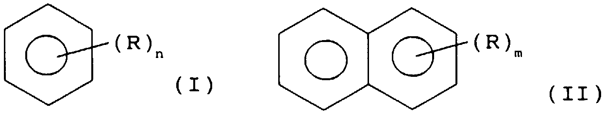
- de façon originale, ledit hydrocarbure liquide est un composé aromatique qui répond à l'une ou à l'autre des formules (I) et (II) ci-après

dans lesquelles : n = 1,2, 3 ou 4,
m = 0,1,2, 3 ou 4,
R représente, indépendamment, un halogène, de préférence
le chlore, ou un groupement alkyle choisi parmi les groupes
méthyle, éthyle, n-propyle ou i-propyle, ou consiste en un mélange d'au moins deux composés aromatiques répondant à l'une ct/ou l'autre desdites formules (I) et (II). More specifically, said first object consists of a method of densifying a porous structure according to which
- conventionally, said porous structure is kept immersed in a liquid hydrocarbon and the whole is heated: porous structure / liquid hydrocarbon, so that the carbon obtained by decomposition of said liquid hydrocarbon is deposited cn part in the pigs of said porous structure (conventional heat-setting process);
and
- In an original way, said liquid hydrocarbon is an aromatic compound which corresponds to one or the other of formulas (I) and (II) below
in which: n = 1,2, 3 or 4,
m = 0,1,2, 3 or 4,
R independently represents a halogen, preferably
chlorine, or an alkyl group chosen from the groups
methyl, ethyl, n-propyl or i-propyl, or consists of a mixture of at least two aromatic compounds corresponding to one or the other of said formulas (I) and (II).
Le précurseur de carbone dont l'inten'ention est préconisée dans Ic cadre de la présente invention, consiste donc
- en un dérive du benzène,
- en le naphtalène,
- en un dérivé du naphtalène,
- ou en un mélange de ces composés.The carbon precursor, the intention of which is recommended in the context of the present invention, therefore consists
- a derivative of benzene,
- in naphthalene,
- into a naphthalene derivative,
- or a mixture of these compounds.
Lesdits dérives du benzène et du naphtalène comportent de 1 à 4 substituants, identiques ou différents, choisis, indépendamment, parmi les halogènes et les alkyles inférieurs. Les dérivés du naphtalène présentent indifféremment leurs substituants sur l'un et/ou l'autre des deux noyaux. Said benzene and naphthalene derivatives contain from 1 to 4 substituents, identical or different, chosen, independently, from halogens and lower alkyls. The naphthalene derivatives have either their substituents on one and / or the other of the two cores.
L'intervention du chlore, à titre de substituant halogéné (X) est particulièrement préférée mais celle, conjointe ou indépendante de celle dudit chlore, des autres halogènes (X=F, Br, I, As) fait partie intégrante du cadre de la présente invention. la présence d'au moins un substituant halogéné (X) dans la structure du précurseur de carbone selon l'invention est avantageuse dans la mesure où la liaison Car-X (Carbone aromatique - Halogène) est une liaison plus faible que les liaisons Car-Calk (Carbone aromatique - Carbone aliphatique) ou Car-H (Carbone aromatique - Hydrogène). The intervention of chlorine, as halogenated substituent (X) is particularly preferred but that, joint or independent of that of said chlorine, of the other halogens (X = F, Br, I, As) forms an integral part of the framework of the present invention. the presence of at least one halogenated substituent (X) in the structure of the carbon precursor according to the invention is advantageous insofar as the Car-X bond (aromatic carbon - Halogen) is a weaker bond than the Car- bonds Calk (Aromatic Carbon - Aliphatic Carbon) or Car-H (Aromatic Carbon - Hydrogen).
L'intervention des substituants alkylés qui peut se révéler opportune pour diverses raisons et notamment en référence à la toxicité des composés a été limitée à celle des alkyles inférieurs, en référence au paramètre rendement en carbone. The intervention of alkyl substituents which may prove to be expedient for various reasons and in particular with reference to the toxicity of the compounds has been limited to that of lower alkyls, with reference to the parameter carbon yield.
On rappelle ici, qu'avec les composés aromatiques identifiés ci-dessus, utilisés à titre d'hydrocarbure liquide, précurseur de carbone dans un procédé de caléfaction, la Demanderesse a obtenu des résultats inattendus, particulièrement avantageux en termes de vitesse de dépôt de carbone, de rendement en carbone, d'énergie consommée .. It will be recalled here that, with the aromatic compounds identified above, used as a liquid hydrocarbon, a carbon precursor in a caulking process, the Applicant has obtained unexpected results, particularly advantageous in terms of carbon deposition rate , carbon yield, energy consumed ..
Comme indiqué ci-dessus, la réaction de caléfaction est mise en oeuvre avec la structure poreuse à densifier immergée dans le précurseur liquide appelé à se décomposer dans la mesure où il est chauffé, généralement par induction et/ou effet Joule, à des températures adéquates. Les précurseurs de l'invention, identifiés ci-dessus, étant des composés, liquides ou solides à la température ambiante, il convient dc prévoir, dans le cadre de la présente invention, des moyens pour assurer la fusion desdits composés solides. Ainsi, prevoit-on avantageusement la fusion desdits composés solides (cxcmple, le 2-méthylnaphtalène) en amont du réacteur de caléfaction (au sein duqucl le procédé de l'invention est mis en oeuvrc) ainsi que l'alimentation, par des moyens adéquats, dudit réacteur cn lesdits composés maintenus à l'état liquide. As indicated above, the caulking reaction is carried out with the porous structure to be densified immersed in the liquid precursor which is called to decompose insofar as it is heated, generally by induction and / or Joule effect, at suitable temperatures. . The precursors of the invention, identified above, being compounds, liquid or solid at room temperature, it is advisable to provide, within the framework of the present invention, means for ensuring the fusion of said solid compounds. Thus, provision is advantageously made for the melting of said solid compounds (cxcmple, 2-methylnaphthalene) upstream of the heat-up reactor (within which the process of the invention is implemented) as well as the supply, by suitable means of said reactor cn said compounds maintained in the liquid state.
Dans le cadre du procédé de caléfaction dc l'invention, on préconise tout particulièrement l'intervention, à titre d'hydrocarbure liquide précurseur de carbone. du chlorobenzène ou du toluène. In the context of the calfaction process of the invention, intervention is particularly recommended, as a liquid hydrocarbon carbon precursor. chlorobenzene or toluene.
Dans ce même cadre, la Demanderesse a apporte d'autres perfectionnements à cc procédé de base mis en oeuvre avec un précurseur aromatique. Lesdits perfectionnements constituent d'autres objets de la présente invention. Ils Sont présentés ci-apres. In this same context, the Applicant has made other improvements to this basic process implemented with an aromatic precursor. Said improvements constitute other objects of the present invention. They are presented below.
Le chauffage mis en oeuvre pour assurer la décomposition du précurseur original de l'invention peut faire intervenir tout type de moyens. Il s'agit généralement d'un chauffage inductif ou d'un chauffage résistif, voire d'un chauffage inductif et/ou résistif. La combinaison de ces deux types de chauffage (i.e. l'intervention conjointe de moyens distincts, adéquats, pour assurer d'une part un chauffage par induction et d'autre part un chauffage par effet Joule) fait partie intégrante du cadre dc la présente invention. Toutefois, la Dcmanderesse préconise plutôt de mettre cn oeuvre le procédé de l'invention soit avec un chauffage inductif, soit avec un chauffage résistif. Lc chauffage inductif est particulièrement préconisé. The heating used to ensure the decomposition of the original precursor of the invention can involve any type of means. It is generally an inductive heating or a resistive heating, even an inductive and / or resistive heating. The combination of these two types of heating (ie the joint intervention of separate, adequate means, to ensure on the one hand induction heating and on the other hand heating by Joule effect) is an integral part of the framework of the present invention. . However, the Applicant recommends rather implementing the method of the invention either with inductive heating or with resistive heating. Inductive heating is particularly recommended.
La mise en oeuvre d'un tel chauffage inductif fait avantageusement intervenir un suscepteur. L'hommc du métier n'ignore pas a priori l'intérêt d'un tel suscepteur (bien évidemment en un matériau adéquat pour qu'il puisse être chauffé par induction). la structure poreuse à densifier est maintenue au contact dudit suscepteur. Un tel contact structure poreuse à densifier/suscepteur peut se décliner selon plusieurs variantcs. La surfacc dc contact peut notamment être plane ou courbe. On peut ainsi "associcr" une structure poreuse plane et un suscepteur plan, deux structures poreuses planes dc part ct d'autre d'un susceptcur plan, une structure poreuse en forme de manchon et un suscepteur cylindrique
On rappelle incidemment ici que le procédé de l'invention peut tout-àfait inclure un chauffage inductif, sans faire intervenir de suscepteur, dans des conditions électromagnétiques dc couplage différentes. Ccci se conçoit aisément pour l'homme du métier.The implementation of such an inductive heating advantageously involves a susceptor. The general public does not ignore the interest of such a susceptor a priori (obviously in an adequate material so that it can be heated by induction). the porous structure to be densified is kept in contact with said susceptor. Such a porous structure to be densified / susceptor contact can be declined according to several variants. The contact surface can in particular be flat or curved. We can thus "associate" a planar porous structure and a planar susceptor, two planar porous structures on the other side of a planar susceptor, a porous structure in the form of a sleeve and a cylindrical susceptor
It is incidentally recalled here that the method of the invention can completely include inductive heating, without involving a susceptor, under different coupling electromagnetic conditions. Ccci is easily designed for the skilled person.
Pour la mise cn ocuvrc d'un chauffage résistif, la structure poreuse à densifier peut constitucr cllc-mcmc Ic résistor. Toutefois, il est généralement avantageux (au vu notamment dc la nature dc la pièce à densifier, dc son épaisseur...) dc faire intervenir un résistor, séparé, isolé électriquement dc ladite structure poreuse à densifier. Ainsi trouvc-t-on généralement entre un tel résistor et ladite structure poreuse, un isolant électrique, aussi bon conductcur thermique que possible, par exemple cn nitrurc dc borc. On parle alors d'un quasi contact entre ladite structure ct ledit résistor. Lcdit quasi contact structure poreuse à densificr/résistor peut lui aussi sc décliner selon plusicurs variantes ; la surfacc de quasi contact pouvant elle aussi être notamment plane ou courbc. On peut aussi trouver au quasi contact d'un résistor plan une (dcux) structurc(s) poreuses plane(s), au quasi contact d'un rcsistor cylindrique une structure poreuse cn forme de manchon. For the installation of resistive heating, the porous structure to be densified may constitute a clc-mcmc Ic resistor. However, it is generally advantageous (in view in particular of the nature of the part to be densified, of its thickness, etc.) to involve a separate, electrically isolated resistor from said porous structure to be densified. Thus is generally found between such a resistor and said porous structure, an electrical insulator, as good thermal conductor as possible, for example cn nitrurc dc borc. We then speak of a quasi contact between said structure and said resistor. Said quasi-contact porous structure to densifier / resistor can also be declined according to several variants; the quasi-contact surface can also be notably flat or curved. One can also find at quasi contact with a planar resistor a (porous) structural porous structure (s), at quasi contact with a cylindrical resistor a porous structure in the form of a sleeve.
Ledit contact ou quasi contact, suscepteur/strueture poreuse à densifier, résistor/structure poreuse à densifier, pouvant poser des problèmes (d'autant plus aigus qu'il est plus intime ; par exemple, dans le cas où la structure poreuse, de forme tubulaire, entoure ledit suscepteur ou ledit résistor)
- lors du refroidissement, en fin de procédé (apparition de fissures dans la structure poreuse densifiée en raison des différences entre le coefficicnt de dilatation de ladite structure ct cclui dudit susccptcur ou cclui dudit résistor)
et
- lors de la récupération de la structure poreuse densifiée (lors de sa désolidarisation dudit suscepteur ou dudit résistor), à l'issue dudit procédé; la Demandercsse a trouvé particulièrement opportun de faire intervenir entre ladite structure poreuse et ledit suscepteur ou ledit résistor un joint de dilatation. Un tel joint, pour développer son action bcnéfique présente généralement une épaisseur d'au moins 1 mm. Il présente avantageusement une épaisseur d'au moins 3 mm. Un tel joint peut avantageusement consistcr en du papier graphite. L'intervention d'un tel joint ne se révèle bien sur opportune que dans les contextes où intervient un suscepteur et/ou un résistor. Elle est a fortiori opportune, comme mentionné plus haut, lorsque la structure poreuse traitée entoure ledit suscepteur et/ou ledit résistor. Même lorsqu'un tel joint dc dilatation intervient, on parle pour des raisons de simplification, de contact ou quasi contact, respectivcmcnt entre la structure poreuse et le suscepteur et entre la structure poreuse ct Ic résistor.Said contact or quasi-contact, porous susceptor / structure to be densified, porous resistor / structure to be densified, which can cause problems (the more acute the more intimate; for example, in the case where the porous structure, tubular, surrounds said susceptor or said resistor)
- during cooling, at the end of the process (appearance of cracks in the densified porous structure due to the differences between the expansion coefficient of said structure and that of said susccptcur or that of said resistor)
and
- during the recovery of the densified porous structure (during its separation from said susceptor or from said resistor), at the end of said process; the Applicant has found it particularly expedient to involve an expansion joint between said porous structure and said susceptor or said resistor. To develop its beneficial action, such a joint generally has a thickness of at least 1 mm. It advantageously has a thickness of at least 3 mm. Such a seal can advantageously consist of graphite paper. The intervention of such a joint is of course only timely in contexts where a susceptor and / or a resistor intervenes. It is a fortiori timely, as mentioned above, when the porous structure treated surrounds said susceptor and / or said resistor. Even when such an expansion joint occurs, we speak for reasons of simplification, of contact or quasi-contact, respectively between the porous structure and the susceptor and between the porous structure and the resistor.
Pour obtenir par ailleurs la densification de la structure poreuse sur toute son épaisseur, qu'un susccptcur ou résistor intcrvicnnc ou pas, la Demandcresse propose une innovation. Elle préconise l'intervention d'une autre structure poreuse au contact dc la(dcs) surfacc(s) libre(s) de ladite structure poreuse à densifier. To also obtain densification of the porous structure over its entire thickness, whether or not a susccptcur or resistor is involved, Demandcresse offers an innovation. It recommends the intervention of another porous structure in contact with the free surface (s) of said porous structure to be densified.
L'épaisseur dc ladite autre structure poreuse est d'au moins 3 mm pour l'obtention de l'effet escompté ; elle est généralement comprisc entre 3 ct 5 mm. Ladite autre structure poreuse peut consistcr cn un fcutre. Ladite autre structure poreuse qui se trouve partiellement densifiée à l'issue du procédé de densification de la structure poreuse, sur toute son épaisseur, intervint au contact dc la (des) surface(s) dc ladite structure poreuse qui, sans elle, scrai(cn)t directement au contact de l'hydrocarbure liquide dans lequel ladite structure poreuse à densifier est immergée.The thickness of said other porous structure is at least 3 mm to obtain the expected effect; it is generally between 3 ct 5 mm. Said other porous structure may consist of a fecre. Said other porous structure which is partially densified at the end of the densification process of the porous structure, over its entire thickness, intervened in contact with the surface (s) of said porous structure which, without it, would scaly ( cn) t directly in contact with the liquid hydrocarbon in which said porous structure to be densified is immersed.
Enfin, la Dcmandcrcssc a constaté que la température de la réaction de densification est avantageusement pilotée en fonction du débit ct dc la composition des gaz dc la réaction; i.c. qu'clle prcconisc la régulation de la puissance du générateur par Ic débit ct la composition desdits gaz. Elle a, dans ces conditions, obtenu des résultats meilleurs par rapport à ceux obtenus avec un pilotage classique, en fonction de la température maximale de la structure poreuse traitée. Finally, the Dcmandcrcssc noted that the temperature of the densification reaction is advantageously controlled as a function of the flow rate ct dc the composition of the reaction gases; i.c. that it is important to regulate the power of the generator by the flow rate and the composition of said gases. Under these conditions, it obtained better results compared to those obtained with conventional control, as a function of the maximum temperature of the porous structure treated.
Le procédé de l'invention est évidemment mis en oeuvre à une température adaptée à la nature du précurseur intervenant. Ledit précurseur doit se décomposer thermiquement pour générer du carbone. Ledit procédé de l'invention est généralement mis en oeuvre à une température d'au moins 800in; avantageusement à une température supérieure à 1 000in. ladite température du procédé est celle de la zone de dépôt (de densification). Elle est proche de la température du susccpteur ou résistor, dans l'hypothèse où un tel suscepteur ou résistor intervient. The process of the invention is obviously carried out at a temperature adapted to the nature of the intervening precursor. Said precursor must thermally decompose to generate carbon. Said method of the invention is generally carried out at a temperature of at least 800in; advantageously at a temperature above 1000in. said process temperature is that of the deposition (densification) zone. It is close to the temperature of the susceptor or resistor, in the event that such a susceptor or resistor intervenes.
Pour ce qui concerne la pression sous laquelle ledit procédé est mis en oeuvre, elle est généralement comprise entre 0,8.105 et 2.105 Pa (entre 0,8 et 2 bars), avantageusement supérieure à 105 Pa (1 bar). On préconise de mettre en oeuvre ledit procédé à une pression supérieure à la pression atmosphérique dans la mesure où, dans de telles conditions, le carbone introduit dans la structure poreuse, se révèle parfaitement graphitisable. As regards the pressure under which said method is implemented, it is generally between 0.8.105 and 2.105 Pa (between 0.8 and 2 bars), advantageously greater than 105 Pa (1 bar). It is recommended to carry out said process at a pressure higher than atmospheric pressure insofar as, under such conditions, the carbon introduced into the porous structure, appears perfectly graphitizable.
Les structures poreuses densifiées selon l'invention sont généralement, à l'issue du traitement de densification, traitées thermiquement, de préférence sous vide, pour éliminer de leur structure, toute trace de l'hydrocarbure qui est intervenu à titre de précurseur de carbone. Elles peuvent ensuite être destinées à divers types d'applications. S'il est prévu de les traiter thermiquement à des fins de graphitisation, on veillera bien évidemment à mettre en oeuvre le procédé de l'invention dans des conditions telles (notamment de prcssion) que le carbone dc densification déposé soit graphitisable. The densified porous structures according to the invention are generally, at the end of the densification treatment, heat treated, preferably under vacuum, to remove from their structure, any trace of the hydrocarbon which has acted as a carbon precursor. They can then be used for various types of applications. If it is planned to heat treat them for graphitization purposes, it will of course be careful to implement the process of the invention under conditions such (especially of precession) that the densification carbon deposited is graphitizable.
Pour ce qui coneeme Ic champ d'application du procédé de l'invention (ci-dessus décrit en termes généraux ct ci-après détaillé cn référence à la figure annexée et illustré par des exemples), on peut préciser ce qui suit et indiquer d'ores et déjà qu'il est très vaste. Le procédé de densification revendiqué peut notamment s appliquer à la densification de feutres, tissus, et plus généralement de structures bi- ou tri-dimensionnelles, à base de fibrcs de carbone ou de fibres céramiques, pouvant être avantageusement utilisés, du fait dc Icur résistance mécanique élevée et de leur bonne résistance aux chocs et à l'abrasion, pour la réalisation de disques de frein, notamment d'avions. Le procédé de l'invention peut de la même façon être mis en oeuvre pour la rénovation de tcls disques de frein. Plus généralement, le procédé de l'invention convint pour la densification, par du carbone, de toute structure poreuse, à base de fibrcs ou autres ... Il peut notamment convenir pour la densification de mousses à porosité ouverte, d'empilements de sphères (en carbone ou en céramiques, par exemple ...) Il peut également constituer un traitement complémentaire pour la densification de pièces présentant une très faible porosité, par exemple de l'ordre de 5 % ... As regards the field of application of the method of the invention (described above in general terms and detailed below with reference to the appended figure and illustrated by examples), the following can be specified and indicate d already it is very large. The densification method claimed can in particular be applied to the densification of felts, fabrics, and more generally of two- or three-dimensional structures, based on carbon fibers or ceramic fibers, which can be advantageously used, due to their resistance. high mechanical strength and good impact and abrasion resistance, for producing brake discs, especially for airplanes. The method of the invention can similarly be implemented for the renovation of tcls brake discs. More generally, the process of the invention is suitable for the densification, by carbon, of any porous structure, based on fibers or other ... It may in particular be suitable for the densification of foams with open porosity, stacks of spheres (in carbon or in ceramics, for example ...) It can also constitute an additional treatment for the densification of parts having a very low porosity, for example of the order of 5% ...
On en vient maintenant au deuxième objet de la présente invention, à savoir un dispositif utile à la mise en oeuvre de son premier objet, i.e. un dispositif utile à la densification par caléfaction d'une structure poreuse, caléfaction mise en oeuvre avec un hydrocarbure liquide du type précisé ci-dessus. Un tel dispositif comprend:
- un réacteur au sein duquel la structure poreuse est immergée dans l'hydrocarbure liquide;
- des moyens pour assurer le chauffage (notamment par induction et/ou effet Joule) de l'ensemble structure poreuse/hydrocarbure liquide
- des moyens de récupération, à l'état liquide, de l'hydrocarbure vaporisé et/ou entraîné - sous forme d'aérosol - par les gaz de réaction.We now come to the second object of the present invention, namely a device useful for the implementation of its first object, ie a device useful for the densification by caulking of a porous structure, caulking implemented with a liquid hydrocarbon. of the type specified above. Such a device includes:
- a reactor in which the porous structure is immersed in the liquid hydrocarbon;
means for heating (in particular by induction and / or Joule effect) of the porous structure / liquid hydrocarbon assembly
means for recovering, in the liquid state, the hydrocarbon vaporized and / or entrained - in the form of an aerosol - by the reaction gases.
Il peut tout-à-fait s'agir d'un dispositif du type de ceux de l'art antérieur et notamment, dans l'hypothèse d'un chauffage inductif, d'un dispositif du type de celui décrit dans la demande FR-A-2 516 914, lorsque I'hydrocarbure utilisé à titre de précurseur de carbone est à l'état liquide à la température ambiante. It may very well be a device of the type of those of the prior art and in particular, in the case of inductive heating, of a device of the type described in the application FR- A-2,516,914, when the hydrocarbon used as carbon precursor is in the liquid state at room temperature.
Dans l'hypothèse où ledit hydrocarbure est à l'état solide à la température ambiante, il convient d'aménager ledit dispositif de l'art antérieur (qu'il englobe des moyens de chauffage inductif et/ou résistif), tant au niveau de l'alimentation du réacteur en ledit hydrocarbure qu'au niveau des moyens dc récupération à l'état liquide dudit hydrocarbure vaporisé ct/ou entraîné par les gaz de réaction. Au niveau de l'alimentation, on prévoit avantageusement des moyens de chauffage adéquats. Au niveau de la récupération, on doit également prévoir des moyens de chauffage adéquats en sus de moyens dc refroidissement classiquement prévus lorsque ledit hydrocarbure est liquide à la température ambiante. En effet, un tel hydrocarbure - liquide à la température ambiante - lorsqu'il est vaporisé et/ou entraîné par les gaz de réaction va se recondenser au contact de moyens de refroidissement et être ainsi aisément recyclé dans Ic réacteur (généralement par simple gravité). Par contre, un hydmearbure - solide à la température ambiante se cristalliserait au niveau de tcls moyens de refroidissement, encrasserait lesdits moyens et ne pourrait être recycle aisément dans Ic réacteur. Avec un tel précurseur lourd, on doit donc prévoir dans le dispositif de l'invention, une combinaison dc moyens de refroidissement et de moyens dc chauffage pour recycler ledit précurseur lourd vaporisé et/ou entraîné par les gaz de réaction. Au niveau desdits moyens de refroidissement, ledit précurseur lourd entraîné doit être condensé sans cristallisation ct au niveau desdits moyens de chauffage ledit précurseur lourd condensé (liquide) doit être maintenu en phase liquide. In the event that said hydrocarbon is in the solid state at ambient temperature, it is advisable to arrange said device of the prior art (that it includes means of inductive and / or resistive heating), both at the level of supplying the reactor with said hydrocarbon only at the level of the means for recovering, in the liquid state, said hydrocarbon vaporized and / or entrained by the reaction gases. In terms of food, it is advantageous to provide adequate heating means. In terms of recovery, adequate heating means must also be provided in addition to the cooling means conventionally provided when said hydrocarbon is liquid at ambient temperature. Indeed, such a hydrocarbon - liquid at room temperature - when it is vaporized and / or entrained by the reaction gases will recondense on contact with cooling means and thus be easily recycled in the reactor (generally by simple gravity) . On the other hand, a hydroburbide - solid at ambient temperature would crystallize at the level of the cooling means, would foul the said means and could not be easily recycled in the reactor. With such a heavy precursor, it is therefore necessary to provide in the device of the invention, a combination of cooling means and heating means for recycling said heavy precursor vaporized and / or entrained by the reaction gases. At said cooling means, said heavy heavy precursor must be condensed without crystallization and at said heating means said heavy condensed precursor (liquid) must be kept in the liquid phase.
On notera incidemment ici que lesdits gaz de réaction consistent principalement en de l'hydrogène ct des hydrocarbures légers du type méthane, éthylène, éthane ... On rappelle ici que la mise en oeuvre du procédé de caléfaction avec les précurseurs originaux de l'invention génère une quantité d'hydrocarbure légers bien plus faible que ladite mise cn ocuvre avec le cyclohexane. Incidentally, it will be noted here that said reaction gases mainly consist of hydrogen and light hydrocarbons of the methane, ethylene, ethane type, etc. It is recalled here that the implementation of the caléfaction process with the original precursors of the invention generates a much lower amount of light hydrocarbon than said setting up with cyclohexane.
Pour ce qui concerne les moyens destinés à assurer le chauffage de l'ensemble structure porcusc/hydrocarbu re liquide précurseur (de carbone), il peut notamment s'agir de moyens convenant pour un chauffage inductif et/ou résistif. As regards the means intended to ensure the heating of the whole porcusc / hydrocarbon liquid precursor structure (carbon), it may in particular be means suitable for inductive and / or resistive heating.
Les moyens convenant pour un chauffage inductif comprennent une bobine d'induction. Ladite bobine d'induction peut être agencée à l'extérieur du réacteur. Elle est avantageusement disposée dans le réacteur, immergée dans l'hydrocarbure liquide, autour dc la structure poreuse. A ladite bobine d'induction est avantageusement associé un suscepteur. The means suitable for inductive heating include an induction coil. Said induction coil can be arranged outside the reactor. It is advantageously placed in the reactor, immersed in the liquid hydrocarbon, around the porous structure. Advantageously associated with said induction coil is a susceptor.
Les moyens convenant pour un chauffage résistif comprennent avantageusement un résistor auqucl on associc, comme précisé plus haut, un isolant électrique, aussi bon conductcur thermique que possiblc. The means suitable for resistive heating advantageously comprise a resistor to which, as specified above, an electrical insulator is associated, as good thermal conductor as possible.
Ainsi, selon des variantes préférées, le réacteur du dispositif dc l'invention renferme un susccptcur ct/ou un résistor, générnlement un suscepteur ou un résistor. Ledit susccptcur ct/ou résistor est prévu au (quasi) contact de la structure poreuse à densifier. On trouve généralement ledit susccptcur ct/ou ledit résistor sur un support ménagé au sein du réacteur, ledit support pouvant avantageusement être rotatif. Ledit support convient également généralement pour supportcr la structure poreuse à densifier et avantageusement l'autre structure poreuse qui peut intervenir au contact dc la (dcs) surfacc(s) librc(s) dc ladite structure poreuse à densifier. Au (quasi) contact dc ladite structure poreuse ct dudit susccptcur ct/ou résistor est avantageusement prévu, comme indiqué plus haut, un joint dc dilatation. Thus, according to preferred variants, the reactor of the device of the invention contains a suscptcur ct / or a resistor, genernlement a susceptor or a resistor. Said susccptcur ct / or resistor is provided for (almost) contacting the porous structure to be densified. Said susccptcur ct / or said resistor is generally found on a support formed within the reactor, said support advantageously being able to be rotary. Said support is also generally suitable for supporting the porous structure to be densified and advantageously the other porous structure which can intervene in contact with the (dcs) surfacc (s) librc (s) dc said porous structure to be densified. At (almost) contact with said porous structure next to said susptpturec / or resistor is advantageously provided, as indicated above, an expansion joint.
On se propose dc décrire plus précisément une variante du procédé de l'invention et un dispositif associé, cn référence à l'unique figure annexée : la figure 1 sur laquelle on a schématisé un dispositif, susceptible d'être utilisé pour la mise en ocuvrc de ladite variante du procédé dc l'invention (variante avec chauffage inductif). It is proposed to describe more precisely a variant of the process of the invention and an associated device, with reference to the single appended figure: FIG. 1 in which a device has been shown diagrammatically, capable of being used for the implementation of said variant of the process of the invention (variant with inductive heating).
A) Ledit dispositif comprend une colonne constituée de trois parties, à savoir un réacteur 1, un dévésiculeur 2 ou piège à aérosols et un condenseur ou échangeur de chaleur 3. La partie réacteur 1 est disposée dans une enceinte de confinement ou boite à gants 4 balayée intérieurement par un courant de gaz neutre. Celle-ci assure la sécurité du manipulateur en cas de rupture du réacteur et permet d'éviter l'inflammation ou l'explosion des gaz de réaction ainsi que l'inhalation du produit par Ic manipulateur. A) Said device comprises a column made up of three parts, namely a reactor 1, a demister 2 or aerosol trap and a condenser or heat exchanger 3. The reactor part 1 is placed in a confinement enclosure or glove box 4 internally swept by a stream of neutral gas. This ensures the safety of the manipulator in the event of a reactor rupture and prevents ignition or explosion of the reaction gases as well as inhalation of the product by the manipulator.
La structure poreuse à densifier 5 est placée sur un support 6 rotatif ou non. Ce support 6 support également (variante représentée), en contact avec la structure poreuse 5, un suscepteur 7 (par exemple un mandrin en graphite dc façon à pouvoir être chauffé par induction). Lc support 6 est monté dans la pa refroidissement (généralement de l'eau). L'échangeur de chaleur 3 permet par refroidissement des vapeurs du précurseur P et par condensation de celles-ci de les renvoyer dans le réacteur 1 (cas du précurseur P, liquide à la température ambiante). (Pour des précurseurs solides à la température ambiante, on prévoit une combinaison adéquate moyens de refroidissement/moyens de chauffage). The porous structure to be densified 5 is placed on a support 6 which may or may not be rotatable. This support 6 also supports (variant shown), in contact with the porous structure 5, a susceptor 7 (for example a graphite mandrel so that it can be heated by induction). Lc support 6 is mounted in the cooling pa (usually water). The heat exchanger 3 makes it possible by cooling the vapors of the precursor P and by condensing them to return them to the reactor 1 (case of the precursor P, liquid at room temperature). (For solid precursors at room temperature, an adequate combination of cooling means / heating means is provided).
Les gaz de réaction sont évacués par l'intermédiaire d'une vanne de régulation de pression 21, et menés au travers d'un conduit jusqu a une installation de traitement des gaz 22 (neutralisation en cas d'emploi de composés halogénés). The reaction gases are evacuated via a pressure regulating valve 21, and led through a conduit to a gas treatment installation 22 (neutralization in the case of the use of halogenated compounds).
La vanne de régulation de pression 21 est pilotée par un régulateur 23 relié à un pressostat 24. Le débit des gaz de craquage est mcsuré par un débitmètre 25. La ligne 26 permet d'effectuer des analyses de gaz.The pressure regulation valve 21 is controlled by a regulator 23 connected to a pressure switch 24. The flow of cracked gases is measured by a flow meter 25. Line 26 allows gas analyzes to be carried out.
L'installation comporte aussi un deuxième pressostat 27 (disposé sur une ligne de sécurité de pression, bas de colonne) afin de connaître la pression dans le réacteur 1, ainsi que deux conduits munis de soupapes de sécurité 28 et 29 afin d'éviter une surpression dans la colonne (tarage à 2 bars). Un explosimètre 30 et un détecteur dc Cl 31 sont également placés à proximité de l'installation pour détecter toute fuite de celle-ci. The installation also includes a second pressure switch 27 (disposed on a pressure safety line, bottom of column) in order to know the pressure in the reactor 1, as well as two conduits provided with safety valves 28 and 29 in order to avoid a overpressure in the column (calibration at 2 bars). An explosimeter 30 and a dc C1 detector 31 are also placed near the installation to detect any leak from it.
Les vannes 32, 33, 34 et 35 permettent l'emploi de la pompe 16, soit pour envoyer du précurseur P pendant le cours du procédé, soit pour faire circuler du solvant S, en circuit fermé, à travers les conduits 14 et 36 pour nettoyer l'installation, en fin d'expérimentation. Valves 32, 33, 34 and 35 allow the use of pump 16, either to send precursor P during the course of the process, or to circulate solvent S, in a closed circuit, through conduits 14 and 36 to clean the installation, at the end of the experiment.
B) Ledit dispositif est utilisé comme indiqué ci-aprcs. B) The said device is used as indicated below.
On dispose la pièce constituée du susccptcur 7 ct dc la structure poreuse 5 sur le support 6 à l'intérieur du réacteur 1. Le suscepteur 7 peut être avantageusement rccouvcrt d'unc fine épaisseur de papier graphite (quelques mm) afin de pouvoir séparer plus facilcmcnt, cn fin dc procédé, ledit susccpteur 7 de ladite structure 5 densifiée. Ledit papier graphite jouc aussi le rôle dc joint de dilatation et évite l'apparition dc fissurcs sur la pièce lors du refroidissement (en raison des différences dc cocfficicnts de dilatation du susccptcur 7 et de la structure 5 densifiée). La structure poreuse 5 peut avantageusement comporter à sa périphérie un feutre dc 3 à 5 mm d'épaisseur afin d'obtcnir une densification sur toute l'épaisseur de ladite structure. We have the part made of the susccptcur 7 ct dc the porous structure 5 on the support 6 inside the reactor 1. The susceptor 7 can advantageously be covered with a thin thickness of graphite paper (a few mm) in order to be able to separate more facilcmcnt, cn end dc process, said suspppteur 7 of said structure 5 densified. Said graphite paper also plays the role of expansion joint and avoids the appearance of cracks on the part during cooling (due to the differences in expansion coefficients of the susccptcur 7 and the densified structure 5). The porous structure 5 can advantageously include at its periphery a felt dc 3 to 5 mm thick in order to obtain densification over the entire thickness of said structure.
On place les thermosondes 12 puis l'on effectue un balayage du réacteur I et de l'enceinte de confinement 4 à l'aide d'un gaz inerte (tcl l'azote), afin de chasser l'oxygène éventuellement présent. On rcmplit alors Ic réacteur 1 avec un précurseur de l'invention, Ic chlorobenzène, par exemple. The thermoprobes 12 are placed and then the reactor I and the confinement enclosure 4 are scanned using an inert gas (tcl nitrogen), in order to expel any oxygen present. The reactor 1 is then filled with a precursor of the invention, for example chlorobenzene.
Après avoir mis en fonctionnement le circuit réfrigérant 20, I'installation de traitement des gaz 22 et les alimentations électriques, c'est à dire la pompe de filtration 17, le générateur 11, le programmateur de température 13 et le régulateur de pression 23, on démarre la montée en température de la pièce (7+5). La pression est fixée à 1,2 bars par l'intermédiaire du régulateur de pression 23. After operating the refrigerant circuit 20, the gas treatment installation 22 and the electrical supplies, that is to say the filtration pump 17, the generator 11, the temperature programmer 13 and the pressure regulator 23, we start the room temperature rise (7 + 5). The pressure is fixed at 1.2 bars via the pressure regulator 23.
Dès que le précurseur entre en ébullition, on supprime le balayage de gaz inerte du réacteur 1. Lorsque l'on atteint la température de craquage du précurseur (environ 800in pour le chlorobenzène) les vapeurs dudit précurseur se décomposent dans la structure poreuse 5, ce qui conduit au dépôt de carbone à l'intérieur des pores du substrat. As soon as the precursor comes to a boil, the inert gas sweeping of the reactor 1 is suppressed. When the cracking temperature of the precursor is reached (approximately 800in for chlorobenzene) the vapors of said precursor decompose in the porous structure 5, this which leads to carbon deposition inside the pores of the substrate.
Plus précisément le craquage se réalise au niveau des parois les plus chaudes de ladite structure poreuse. Lorsque la structure poreuse 5 est montée sur un suscepteur 7 - comme c'est le cas présentement - le front de densification se propage de l'intérieur de ladite structure poreuse 5 vers la paroi extérieure. More precisely, cracking takes place at the hottest walls of said porous structure. When the porous structure 5 is mounted on a susceptor 7 - as is presently the case - the densification front propagates from the interior of said porous structure 5 to the exterior wall.
(Lorsqu'il n'y a pas de suscepteur, le front de densification progrcssc depuis l'intérieur de la structure poreuse vers ses parois extérieures placées au contact du précurseur liquide).(When there is no susceptor, the densification front progresses from the inside of the porous structure to its outer walls placed in contact with the liquid precursor).
La vitesse d'avancée du front de densification peut varier de quelques dixièmes de mm/h au centimètre /h, en fonction de la température maximale de la pièce (7+5) et de sa nature (type de porosité). la température est contrôlée par le programmateur 13 relié au thermocouple 12 placé dans le suscepteur 7 (ou au centre de la structure poreuse, lorsqu'il n'y a pas de suscepteur). La mesure, par le débitmètre 25, des débits de gaz dc réaction et la connaissance de leur composition permettent de calculer la vitesse d'avancée du front de densification. The speed of advance of the densification front can vary from a few tenths of mm / h to the centimeter / h, depending on the maximum temperature of the part (7 + 5) and on its nature (type of porosity). the temperature is controlled by the programmer 13 connected to the thermocouple 12 placed in the susceptor 7 (or in the center of the porous structure, when there is no susceptor). The measurement, by the flow meter 25, of the reaction gas flow rates and the knowledge of their composition make it possible to calculate the speed of advance of the densification front.
L'ajout (en continu ou non) de précurseur P est effectué afin de conserver une quantité constante de précurseur dans le réacteur 1. The addition (precursor or not) of precursor P is carried out in order to keep a constant amount of precursor in reactor 1.
Le mélange gaz de réaction, vapeur non craquée et aérosols produits dans le réacteur 1 est évacue en partie haute de celui-ci. Les aérosols et les vapeurs sont condensés au niveau du dévésîculeur 2 et de l'échangeur 3; les gaz de reaction sont extraits en partie haute de l'installation et neutralisés dans l'installation de traitement des gaz 22. Lorsque le front de densification est à environ 3 mm du bord externe de la structure poreuse, (du bord externe du feutre, lorsqu'un feutre intervient) le débit chute de manière importante, même pour une augmentation de manière significative de la puissance (10 ^X). Cela est dû à ce que l'épaisseur dans laquelle a lieu le dépôt devient de plus en plus étroite, compte tenu d'une augmentation du gradient thermique (la distance entre le front de température maximale et la zone où l'on est à la température d'ébullition se réduit). On diminue alors progressivement la température jusqu'à la température ambiante. The mixture of reaction gas, non-cracked vapor and aerosols produced in reactor 1 is discharged at the top of it. The aerosols and vapors are condensed at the level of the demister 2 and of the exchanger 3; the reaction gases are extracted in the upper part of the installation and neutralized in the gas treatment installation 22. When the densification front is approximately 3 mm from the outer edge of the porous structure, (from the outer edge of the felt, when a felt device intervenes) the flow drops significantly, even for a significant increase in power (10 ^ X). This is due to the fact that the thickness in which the deposition takes place becomes more and more narrow, taking into account an increase in the thermal gradient (the distance between the front of maximum temperature and the zone where one is at the boiling point is reduced). The temperature is then gradually reduced to room temperature.
La pièce obtenuc est alors récupérée et subit un traitement thermique de 500'C environ à l'étuve sous vide afin dc rctirer le précurseur résiduel imprégnant les porosités rcstantes. Le suscepteur 7 est séparé de l'ensemble ct la partie extérieure de la pièce non densifiée (structure ou fcutre ajouté, s'il y cn avait un) est usinée. The obtained part is then recovered and undergoes a heat treatment of approximately 500 ° C. in a vacuum oven in order to decant the residual precursor permeating the remaining porosities. The susceptor 7 is separated from the assembly and the external part of the non-densified part (structure or structure added, if there was one) is machined.
Selon une variante avantageuse, on vidange le précurseur alors que la pièce traitée est encore chaude; ce qui permet de mettre en oeuvre son séchage sans manipulation dc cclle-ci. Le traitement thermique, destiné à la débarrasser du précurseur résiduel imprégnant ses porosités restantes, peut alors être mis en oeuvre soit au sein du réacteur, soit comme indiqué plus haut dans une étuve. According to an advantageous variant, the precursor is emptied while the treated part is still hot; which makes it possible to carry out its drying without handling it. The heat treatment, intended to rid it of the residual precursor impregnating its remaining porosities, can then be implemented either within the reactor, or as indicated above in an oven.
Les substrats ainsi densifiés selon l'invention sont homogènes, de densité supérieure ou égale à 1,7 et possèdent, après caractérisation par microscopie optique en lumière polarisée, une structure laminaire rugueuse. Cette structure est la plus intéressante car elle permet d'obtenir, par traitement thermique à haute température (2 400 C), une structure prochc du graphite. La distancc interplans est d002 = 3,36 Â et la taille des cristallites est Lc N 1000A. The substrates thus densified according to the invention are homogeneous, with a density greater than or equal to 1.7 and have, after characterization by optical microscopy in polarized light, a rough laminar structure. This structure is the most interesting because it makes it possible to obtain, by high temperature heat treatment (2400 ° C.), a structure close to graphite. The interplanar distance is d002 = 3.36 Å and the size of the crystallites is Lc N 1000A.
On illustre maintenant l'invention par les deux exemples ci-après. Ils sont à considérer cn référence à la figure 1 annexée ct aux commcntaircs développés cidessus cn référence à ladite figure 1. L'intérêt dc ladite invention est par ailleurs mis cn évidence à la considération de l'exemple comparatif donné entre lesdits deux cxcmplcs. The invention is now illustrated by the following two examples. They are to be considered with reference to FIG. 1 appended and to the descriptions developed above, with reference to said FIG. 1. The advantage of said invention is moreover brought to light by consideration of the comparative example given between said two cxcmplcs.
Exemple I
Lc précurseur utilisé est Ic chlorobenzène.Example I
The precursor used is Ic chlorobenzene.
Lc réacteur employé a un diamètre intérieur de 200 mm, une hauteur de 300 mm. L'inductcur, qui sc trouvc dans Ic réacteur, possède une hauteur dc 150 mm ct est constitué de 6 spircs dc diamètres intérieur ct extérieur ayant respectivement pour valeurs 175 mm ct 195 mm. The reactor used has an internal diameter of 200 mm, a height of 300 mm. The inductor, which is located in the reactor, has a height of 150 mm and is made up of 6 tubes with internal and external diameters having values of 175 mm and 195 mm respectively.
Le susccpteur cmployé est de diamètre 80 mm, hauteur 100 mm. Il est entièrement recouvert à l'aide de préformes fibrcuscs (fibrcs dc carbone)(densité 0,40 à 0,45) à densifier; lesdites préformes sc présentant sous la forme
- d'un cylindre creux de diamètrcs intéricur ct extérieur 80 et 160 mm, hauteur 100 mm, recouvrant sa surface latérale (préforme, commercialisée sous la marque Novoltex#, tclle que décrite dans FR-A-2 584 107),
- de deux disques diamètre 160 mm, épaisseur 40 mm rccouvrant en partie haute et basse ses deux surfaces planes (préformes, commercialisées sous la marque Aiguitex#, telles que décrites dans FR-A-2 584 106).The deployed cm switch is 80 mm in diameter, 100 mm high. It is completely covered using fibrous preforms (carbon fibers) (density 0.40 to 0.45) to be densified; said preforms sc having the form
- a hollow cylinder with inner diameters on the outside 80 and 160 mm, height 100 mm, covering its lateral surface (preform, marketed under the brand Novoltex #, as described in FR-A-2 584 107),
- two 160 mm diameter discs, 40 mm thick covering at the top and bottom its two flat surfaces (preforms, sold under the brand Aiguitex #, as described in FR-A-2 584 106).
La masse totale de préformes fibreuscs rcpréscnte 1 240 g. The total mass of fibrous preforms represents 1,240 g.
La pression est fixée à 1,2 bar. Le réacteur est rempli de chlorobenzène. The pressure is fixed at 1.2 bar. The reactor is filled with chlorobenzene.
La montée en température s'cffcctue à une vitesse de 500 C/h jusqu'à 1 100 C. Le débit de gaz craqués est alors d'environ 8,5 I/min et l'on ajuste la puissance au cours du temps dc manière à conserver ce débit à peu près constant. Après environ 9 h de densification, on procède à la descente en température à une vitesse de 800 C/h.The rise in temperature takes place at a speed of 500 C / h up to 1100 C. The flow rate of cracked gases is then approximately 8.5 I / min and the power is adjusted over time dc so as to keep this flow more or less constant. After approximately 9 h of densification, the temperature is lowered at a speed of 800 C / h.
La masse de carbone déposée représente 3 810 g, pour une consommation de chlorobenzène de 6 1. Le rendement cn carbone calculé est de 88 % (il passe à 96 % si l'on ne considère pas comme consommées, environ 3 moles de chlorobenzène, entraînées par les gaz de réaction et qu'il est possible de récupérer, par condensation, à - 5 C). La vitesse de densification a été de 4,1 mm/h et la consommation électrique d'environ 60 kWh/kg de carbone déposé. The mass of carbon deposited represents 3,810 g, for a consumption of chlorobenzene of 6 1. The carbon yield calculated is 88% (it increases to 96% if we do not consider as consumed, approximately 3 moles of chlorobenzene, entrained by the reaction gases and which it is possible to recover, by condensation, at - 5 C). The densification speed was 4.1 mm / h and the electrical consumption of approximately 60 kWh / kg of carbon deposited.
Après usinage des 3 mm cxtéricurs, la densité des différentes picces est de 1,72. Le carbone obtenu est dc structure du type laminaire rugueux précité. After machining the 3 mm cxtéricurs, the density of the different pits is 1.72. The carbon obtained is of the abovementioned rough laminar type structure.
Exemple comparatif
Lc précurseur utilisé est Ic cyclohexane. Comparative example
The precursor used is Ic cyclohexane.
Il est utilisé dans les conditions dc l'exemple 1. Les résultats obtenus pcrmcttcnt de calculer:
- avec une consommation dc 61 litrcs dc cyclohexane, un rendement cn carbone dc 9 %;
- une vitesse dc densification dc 1,9 mm/h
- une consommation électrique dc 120 kWh/kg (de carbone déposé).It is used under the conditions of Example 1. The results obtained allow to calculate:
- with a consumption of 61 liters of cyclohexane, a carbon yield of 9%;
- a densification speed of 1.9 mm / h
- an electrical consumption of 120 kWh / kg (of carbon deposited).
Exemple 2
Le précurseur utilisé est Ic toluène. Example 2
The precursor used is Ic toluene.
Lc réacteur ct l'inducteur employés sont les mêmes que pour l'exemple 1 avec le chlorobenzène. Le susccptcur possède un diamètre de 80 mm et une hauteur de 156 mm ct est revêtu dc papier graphite (joint dc dilatation) sur une épaisseur de 2 mm. Il est recouveru:
- sur sa surface latérale par la pièce à densifier qui est un manchon fibreux en carbone (densité 0,4) de hauteur 140 mm, G extérieur 165 mm.The reactor and the inductor used are the same as for Example 1 with chlorobenzene. The susccptcur has a diameter of 80 mm and a height of 156 mm and is coated with graphite paper (expansion joint) to a thickness of 2 mm. It is recovered:
- on its lateral surface by the part to be densified which is a fibrous carbon sleeve (density 0.4) of height 140 mm, outside G 165 mm.
- sur ses surfaces planes haute et basse par deux disques de feutre carbone (densité 0,1) de diamètre 165 mm et d'épaisseur 6 mm. - on its high and low flat surfaces by two carbon felt discs (density 0.1) with a diameter of 165 mm and a thickness of 6 mm.
La pression est fixée à 1 bar. Le réacteur est rempli dc toluène (11 1). La montée en température s'cffcctue à une vitesse de 500iC/h jusqu'à 1 00il. Le débit de gaz dc réaction est d'environ 3 I/min ct l'on ajuste la puissance au cours du temps afin de garder une vitesse d'avancée du front de densification à peu près constante. Après 6 heures de densification, on procède à la descente en température à une vitesse de 8000C/h. The pressure is fixed at 1 bar. The reactor is filled with toluene (11 l). The rise in temperature takes place at a speed of 500iC / h until 1 00il. The reaction gas flow rate is approximately 3 l / min and the power is adjusted over time in order to keep the speed of advancement of the densification front more or less constant. After 6 hours of densification, the temperature is lowered at a speed of 8000C / h.
La masse de carbone totalc déposée est de 3 510 g pour une consommation de 7,5 I de toluène. Le rendement en carbone calculé est de 60 %. The mass of total carbon deposited is 3,510 g for a consumption of 7.5 I of toluene. The calculated carbon yield is 60%.
La vitesse de densification a été de 6 mm/h et la consommation énergétique de 60 kWh/kg de carbone dépose. The densification speed was 6 mm / h and the energy consumption of 60 kWh / kg of carbon deposited.
Après usinage des 3 mm extérieurs du manchon densifié, la densité dudit manchon est de 1,75 . Le carbone obtenu est de structure du type laminaire rugueux précité. After machining the 3 mm outside of the densified sleeve, the density of said sleeve is 1.75. The carbon obtained is of the aforementioned rough laminar type structure.
L'emploi du toluène au licu du cyclohexane permet, de même que pour le chlorobenzène, des augmcntations extrêmement importantes de la vitesse dc densification ct du rendement maticrc ainsi qu'une diminution de la consommation énergétique. The use of toluene in addition to cyclohexane allows, as with chlorobenzene, extremely significant increases in the rate of densification and the material yield as well as a reduction in energy consumption.
Claims (10)
Priority Applications (4)
| Application Number | Priority Date | Filing Date | Title |
|---|---|---|---|
| FR9702986A FR2760741B1 (en) | 1997-03-13 | 1997-03-13 | METHOD FOR DENSIFICATION OF A POROUS STRUCTURE INVOLVING AN ORIGINAL PRECURSOR AND ASSOCIATED DEVICE |
| EP98914915A EP0968154B1 (en) | 1997-03-13 | 1998-03-13 | Method for densifying a porous structure using an aromatic precursor |
| DE69818980T DE69818980T2 (en) | 1997-03-13 | 1998-03-13 | METHOD FOR DENSIFYING A POROUS STRUCTURE USING AN AROMATIC PRE-PRODUCT |
| PCT/FR1998/000515 WO1998040327A1 (en) | 1997-03-13 | 1998-03-13 | Method for densifying a porous structure using an aromatic precursor |
Applications Claiming Priority (1)
| Application Number | Priority Date | Filing Date | Title |
|---|---|---|---|
| FR9702986A FR2760741B1 (en) | 1997-03-13 | 1997-03-13 | METHOD FOR DENSIFICATION OF A POROUS STRUCTURE INVOLVING AN ORIGINAL PRECURSOR AND ASSOCIATED DEVICE |
Publications (2)
| Publication Number | Publication Date |
|---|---|
| FR2760741A1 true FR2760741A1 (en) | 1998-09-18 |
| FR2760741B1 FR2760741B1 (en) | 1999-05-28 |
Family
ID=9504696
Family Applications (1)
| Application Number | Title | Priority Date | Filing Date |
|---|---|---|---|
| FR9702986A Expired - Fee Related FR2760741B1 (en) | 1997-03-13 | 1997-03-13 | METHOD FOR DENSIFICATION OF A POROUS STRUCTURE INVOLVING AN ORIGINAL PRECURSOR AND ASSOCIATED DEVICE |
Country Status (4)
| Country | Link |
|---|---|
| EP (1) | EP0968154B1 (en) |
| DE (1) | DE69818980T2 (en) |
| FR (1) | FR2760741B1 (en) |
| WO (1) | WO1998040327A1 (en) |
Cited By (3)
| Publication number | Priority date | Publication date | Assignee | Title |
|---|---|---|---|---|
| FR2784695A1 (en) * | 1998-10-20 | 2000-04-21 | Snecma | DENSIFICATION OF POROUS STRUCTURES BY CHEMICAL STEAM INFILTRATION |
| FR2815890A1 (en) * | 2000-10-30 | 2002-05-03 | Commissariat Energie Atomique | IMPROVEMENT IN DENSIFICATION PROCESSES BY CALEFACTION OF A POROUS STRUCTURE |
| WO2008017677A2 (en) | 2006-08-07 | 2008-02-14 | Messier-Bugatti | Apparatus for porous material densification |
Citations (3)
| Publication number | Priority date | Publication date | Assignee | Title |
|---|---|---|---|---|
| EP0081409A1 (en) * | 1981-11-26 | 1983-06-15 | Commissariat à l'Energie Atomique | Process for increasing the density of porous structures |
| WO1990015776A1 (en) * | 1989-06-14 | 1990-12-27 | Temple University | Process for production of graphite flakes and films via low temperature pyrolysis |
| US5547717A (en) * | 1992-10-09 | 1996-08-20 | Avco Corporation | Method for densifying and refurbishing brakes |
-
1997
- 1997-03-13 FR FR9702986A patent/FR2760741B1/en not_active Expired - Fee Related
-
1998
- 1998-03-13 EP EP98914915A patent/EP0968154B1/en not_active Expired - Lifetime
- 1998-03-13 WO PCT/FR1998/000515 patent/WO1998040327A1/en active IP Right Grant
- 1998-03-13 DE DE69818980T patent/DE69818980T2/en not_active Expired - Lifetime
Patent Citations (3)
| Publication number | Priority date | Publication date | Assignee | Title |
|---|---|---|---|---|
| EP0081409A1 (en) * | 1981-11-26 | 1983-06-15 | Commissariat à l'Energie Atomique | Process for increasing the density of porous structures |
| WO1990015776A1 (en) * | 1989-06-14 | 1990-12-27 | Temple University | Process for production of graphite flakes and films via low temperature pyrolysis |
| US5547717A (en) * | 1992-10-09 | 1996-08-20 | Avco Corporation | Method for densifying and refurbishing brakes |
Non-Patent Citations (1)
| Title |
|---|
| YOSHIKAZU NAKAMURA ET AL: "IR ABSORPTION AND RAMAN SPECTRA OF AS-DEPOSITED AND ANNEALED HYDROGENATED AMORPHOUS CARBON FILMS BY PLASMA DECOMPOSITION OF TOLUENE", JOURNAL OF THE AMERICAN CERAMIC SOCIETY, vol. 74, no. 11, 1 November 1991 (1991-11-01), pages 2932 - 2933, XP000243579 * |
Cited By (8)
| Publication number | Priority date | Publication date | Assignee | Title |
|---|---|---|---|---|
| FR2784695A1 (en) * | 1998-10-20 | 2000-04-21 | Snecma | DENSIFICATION OF POROUS STRUCTURES BY CHEMICAL STEAM INFILTRATION |
| US6410088B1 (en) * | 1998-10-20 | 2002-06-25 | Societe Nationale D'etude Et De Construction De Moteurs D'aviation S.N.E.C.M.A. | CVI (chemical vapor infiltration) densification of porous structures |
| FR2815890A1 (en) * | 2000-10-30 | 2002-05-03 | Commissariat Energie Atomique | IMPROVEMENT IN DENSIFICATION PROCESSES BY CALEFACTION OF A POROUS STRUCTURE |
| WO2002036520A1 (en) * | 2000-10-30 | 2002-05-10 | Commissariat A L'energie Atomique | Improvements to methods for calefaction densification of a porous structure |
| US6994886B2 (en) | 2000-10-30 | 2006-02-07 | Commissariat A L'energie Atomique | Methods for calefaction densification of a porous structure |
| KR100822897B1 (en) * | 2000-10-30 | 2008-04-16 | 꼼미사리아 아 레네르지 아토미끄 | Improvements to methods for calefaction densification of a porous structure |
| WO2008017677A2 (en) | 2006-08-07 | 2008-02-14 | Messier-Bugatti | Apparatus for porous material densification |
| WO2008017677A3 (en) * | 2006-08-07 | 2008-04-10 | Messier Bugatti | Apparatus for porous material densification |
Also Published As
| Publication number | Publication date |
|---|---|
| EP0968154A1 (en) | 2000-01-05 |
| FR2760741B1 (en) | 1999-05-28 |
| DE69818980T2 (en) | 2004-08-12 |
| EP0968154B1 (en) | 2003-10-15 |
| WO1998040327A1 (en) | 1998-09-17 |
| DE69818980D1 (en) | 2003-11-20 |
Similar Documents
| Publication | Publication Date | Title |
|---|---|---|
| DK3167694T3 (en) | Apparatus and method for plasma synthesis of graphite products comprising graphene | |
| EP0256073B1 (en) | Plant for the chemical infiltration in vapor phase of a refractory material other than carbon | |
| EP1332120B1 (en) | Improvements to methods for calefaction densification of a porous structure | |
| EP0819105A1 (en) | Chemical vapour infiltration method with variable infiltration parameters | |
| FR2983192A1 (en) | METHOD FOR COATING A COATING OF A COATING AGAINST OXIDATION BY A CHEMICAL VAPOR DEPOSITION TECHNIQUE, AND COATING AND ROOM | |
| FR2784695A1 (en) | DENSIFICATION OF POROUS STRUCTURES BY CHEMICAL STEAM INFILTRATION | |
| EP1527031B1 (en) | Method and device for high-temperature heat treatment and densification by chemical infiltration of carbon texture in a steam phase | |
| FR2803603A1 (en) | DIAMOND COATING IN THE FORM OF THIN OR THIN FILM RESISTANT TO EROSION AND CORROSION, AND APPLICATIONS THEREOF | |
| EP0968154B1 (en) | Method for densifying a porous structure using an aromatic precursor | |
| EP1456433B1 (en) | Method for monitoring the course of a process using a reactive gas containing one or several hydrocarbons | |
| EP0951462B1 (en) | Thermochemical treatment, in halogenated atmosphere, of a carbon-containing material, non-porous, slightly or very porous | |
| CA1314441C (en) | Process for the preparation of a transparent inner doping glass tube, especially suitable for rare earth-doped fiber optics | |
| FR2671095A1 (en) | PROCESS AND OVEN FOR MANUFACTURING PRODUCTS IN A TUBE WITHOUT DEPOSIT. | |
| FR2885542A1 (en) | Forming a solid deposit on or inside a porous substrate uses fluid compound and reagent applied at a given temperature and pressure | |
| EP0966413B1 (en) | Method for densifying a porous structure by circulation of the precursor and associated device | |
| EP0730564B1 (en) | Method for densifying a porous structure using boron nitride | |
| FR2732962A1 (en) | PROCESS FOR CHEMICAL STEAM INFILTRATION OF MATERIAL COMPOSED OF CARBON AND SILICON AND / OR BORON | |
| JP2003522747A (en) | Processing of fluorocarbon raw materials | |
| BE491423A (en) | ||
| CA1113692A (en) | Cleaning method for the internal walls of a chemical reactor | |
| EP3585754B1 (en) | Method for preparing composite materials with an oxide matrix and oxide reinforcements by means of a heating process | |
| FR2474043A1 (en) | PROCESS AND DEVICE FOR MANUFACTURING CARBON BLACK AND CARBON BLACK OBTAINED | |
| Tyndall et al. | Laser-assisted chemical vapor deposition of graphite | |
| FR2842191A1 (en) | PROCESS AND PLANT FOR HEAT TREATMENT OF SODIUM-CONTAINING CARBON PRODUCTS | |
| WO2023111421A1 (en) | Thermochemical treatment facility and process for manufacturing a composite friction component |
Legal Events
| Date | Code | Title | Description |
|---|---|---|---|
| TP | Transmission of property | ||
| CD | Change of name or company name | ||
| TP | Transmission of property | ||
| ST | Notification of lapse |
Effective date: 20061130 |