ES2941247T3 - A voltage source converter - Google Patents
A voltage source converter Download PDFInfo
- Publication number
- ES2941247T3 ES2941247T3 ES15738384T ES15738384T ES2941247T3 ES 2941247 T3 ES2941247 T3 ES 2941247T3 ES 15738384 T ES15738384 T ES 15738384T ES 15738384 T ES15738384 T ES 15738384T ES 2941247 T3 ES2941247 T3 ES 2941247T3
- Authority
- ES
- Spain
- Prior art keywords
- phase
- active
- reactive
- current reference
- power
- Prior art date
- Legal status (The legal status is an assumption and is not a legal conclusion. Google has not performed a legal analysis and makes no representation as to the accuracy of the status listed.)
- Active
Links
Classifications
-
- H—ELECTRICITY
- H02—GENERATION; CONVERSION OR DISTRIBUTION OF ELECTRIC POWER
- H02J—CIRCUIT ARRANGEMENTS OR SYSTEMS FOR SUPPLYING OR DISTRIBUTING ELECTRIC POWER; SYSTEMS FOR STORING ELECTRIC ENERGY
- H02J3/00—Circuit arrangements for ac mains or ac distribution networks
- H02J3/26—Arrangements for eliminating or reducing asymmetry in polyphase networks
-
- H—ELECTRICITY
- H02—GENERATION; CONVERSION OR DISTRIBUTION OF ELECTRIC POWER
- H02J—CIRCUIT ARRANGEMENTS OR SYSTEMS FOR SUPPLYING OR DISTRIBUTING ELECTRIC POWER; SYSTEMS FOR STORING ELECTRIC ENERGY
- H02J3/00—Circuit arrangements for ac mains or ac distribution networks
- H02J3/18—Arrangements for adjusting, eliminating or compensating reactive power in networks
- H02J3/1821—Arrangements for adjusting, eliminating or compensating reactive power in networks using shunt compensators
- H02J3/1835—Arrangements for adjusting, eliminating or compensating reactive power in networks using shunt compensators with stepless control
- H02J3/1842—Arrangements for adjusting, eliminating or compensating reactive power in networks using shunt compensators with stepless control wherein at least one reactive element is actively controlled by a bridge converter, e.g. active filters
-
- H—ELECTRICITY
- H02—GENERATION; CONVERSION OR DISTRIBUTION OF ELECTRIC POWER
- H02M—APPARATUS FOR CONVERSION BETWEEN AC AND AC, BETWEEN AC AND DC, OR BETWEEN DC AND DC, AND FOR USE WITH MAINS OR SIMILAR POWER SUPPLY SYSTEMS; CONVERSION OF DC OR AC INPUT POWER INTO SURGE OUTPUT POWER; CONTROL OR REGULATION THEREOF
- H02M1/00—Details of apparatus for conversion
- H02M1/0003—Details of control, feedback or regulation circuits
- H02M1/0025—Arrangements for modifying reference values, feedback values or error values in the control loop of a converter
-
- H—ELECTRICITY
- H02—GENERATION; CONVERSION OR DISTRIBUTION OF ELECTRIC POWER
- H02M—APPARATUS FOR CONVERSION BETWEEN AC AND AC, BETWEEN AC AND DC, OR BETWEEN DC AND DC, AND FOR USE WITH MAINS OR SIMILAR POWER SUPPLY SYSTEMS; CONVERSION OF DC OR AC INPUT POWER INTO SURGE OUTPUT POWER; CONTROL OR REGULATION THEREOF
- H02M7/00—Conversion of ac power input into dc power output; Conversion of dc power input into ac power output
- H02M7/66—Conversion of ac power input into dc power output; Conversion of dc power input into ac power output with possibility of reversal
- H02M7/68—Conversion of ac power input into dc power output; Conversion of dc power input into ac power output with possibility of reversal by static converters
- H02M7/72—Conversion of ac power input into dc power output; Conversion of dc power input into ac power output with possibility of reversal by static converters using discharge tubes with control electrode or semiconductor devices with control electrode
- H02M7/79—Conversion of ac power input into dc power output; Conversion of dc power input into ac power output with possibility of reversal by static converters using discharge tubes with control electrode or semiconductor devices with control electrode using devices of a triode or transistor type requiring continuous application of a control signal
- H02M7/797—Conversion of ac power input into dc power output; Conversion of dc power input into ac power output with possibility of reversal by static converters using discharge tubes with control electrode or semiconductor devices with control electrode using devices of a triode or transistor type requiring continuous application of a control signal using semiconductor devices only
-
- Y—GENERAL TAGGING OF NEW TECHNOLOGICAL DEVELOPMENTS; GENERAL TAGGING OF CROSS-SECTIONAL TECHNOLOGIES SPANNING OVER SEVERAL SECTIONS OF THE IPC; TECHNICAL SUBJECTS COVERED BY FORMER USPC CROSS-REFERENCE ART COLLECTIONS [XRACs] AND DIGESTS
- Y02—TECHNOLOGIES OR APPLICATIONS FOR MITIGATION OR ADAPTATION AGAINST CLIMATE CHANGE
- Y02E—REDUCTION OF GREENHOUSE GAS [GHG] EMISSIONS, RELATED TO ENERGY GENERATION, TRANSMISSION OR DISTRIBUTION
- Y02E40/00—Technologies for an efficient electrical power generation, transmission or distribution
- Y02E40/20—Active power filtering [APF]
-
- Y—GENERAL TAGGING OF NEW TECHNOLOGICAL DEVELOPMENTS; GENERAL TAGGING OF CROSS-SECTIONAL TECHNOLOGIES SPANNING OVER SEVERAL SECTIONS OF THE IPC; TECHNICAL SUBJECTS COVERED BY FORMER USPC CROSS-REFERENCE ART COLLECTIONS [XRACs] AND DIGESTS
- Y02—TECHNOLOGIES OR APPLICATIONS FOR MITIGATION OR ADAPTATION AGAINST CLIMATE CHANGE
- Y02E—REDUCTION OF GREENHOUSE GAS [GHG] EMISSIONS, RELATED TO ENERGY GENERATION, TRANSMISSION OR DISTRIBUTION
- Y02E40/00—Technologies for an efficient electrical power generation, transmission or distribution
- Y02E40/30—Reactive power compensation
-
- Y—GENERAL TAGGING OF NEW TECHNOLOGICAL DEVELOPMENTS; GENERAL TAGGING OF CROSS-SECTIONAL TECHNOLOGIES SPANNING OVER SEVERAL SECTIONS OF THE IPC; TECHNICAL SUBJECTS COVERED BY FORMER USPC CROSS-REFERENCE ART COLLECTIONS [XRACs] AND DIGESTS
- Y02—TECHNOLOGIES OR APPLICATIONS FOR MITIGATION OR ADAPTATION AGAINST CLIMATE CHANGE
- Y02E—REDUCTION OF GREENHOUSE GAS [GHG] EMISSIONS, RELATED TO ENERGY GENERATION, TRANSMISSION OR DISTRIBUTION
- Y02E40/00—Technologies for an efficient electrical power generation, transmission or distribution
- Y02E40/50—Arrangements for eliminating or reducing asymmetry in polyphase networks
Landscapes
- Engineering & Computer Science (AREA)
- Power Engineering (AREA)
- Control Of Electrical Variables (AREA)
- Electrophonic Musical Instruments (AREA)
- Burglar Alarm Systems (AREA)
- Details Of Television Scanning (AREA)
- Supply And Distribution Of Alternating Current (AREA)
Abstract
En el campo de las redes de transmisión de energía de corriente continua de alto voltaje (HVDC), un convertidor de fuente de voltaje (10) que comprende un controlador (36) configurado para; recibir una orden de potencia activa que comprende la cantidad deseada de potencia activa a transferir por el convertidor y recibir una orden de potencia reactiva que comprende la cantidad deseada de potencia reactiva a transferir por el convertidor; recibir una medida de la tensión instantánea de cada fase de la red eléctrica AC multifásica; determinar un valor de referencia de corriente de fase activa y reactiva para cada rama monofásica que sea independiente de la referencia de corriente de fase respectiva o de cada otra y que defina la corriente que cada rama monofásica debe extraer o pasar a una fase correspondiente de la Red eléctrica AC para efectuar los intercambios de potencia activa y potencia reactiva con la red eléctrica AC definida por los órdenes de potencia activa y reactiva; los valores de referencia de corriente de fase activa determinados en base a la orden de potencia activa recibida, las mediciones de voltaje instantáneo y una determinación de una potencia reactiva instantánea resultante utilizando dichos valores de referencia de corriente de fase activa; y/o los valores de referencia de la corriente de fase reactiva determinados en función del orden de potencia reactiva recibido, (Traducción automática con Google Translate, sin valor legal)In the field of high voltage direct current (HVDC) power transmission networks, a voltage source converter (10) comprising a controller (36) configured to; receiving an active power command comprising the desired amount of active power to be transferred by the converter and receiving a reactive power command comprising the desired amount of reactive power to be transferred by the converter; receive a measurement of the instantaneous voltage of each phase of the multiphase AC electrical network; determine an active and reactive phase current reference value for each single-phase branch that is independent of the respective phase current reference or each other and that defines the current that each single-phase branch must draw or pass to a corresponding phase of the AC electrical network to exchange active power and reactive power with the AC electrical network defined by the active and reactive power orders; active phase current reference values determined based on the received active power command, instantaneous voltage measurements and a determination of a resulting instantaneous reactive power using said active phase current reference values; and/or the reference values of the reactive phase current determined based on the order of reactive power received, (Automatic translation with Google Translate, without legal value)
Description
DESCRIPCIÓNDESCRIPTION
Un convertidor de fuente de tensiónA voltage source converter
La presente invención se refiere a un convertidor de fuente de tensión. En particular, se refiere a un convertidor de fuente de tensión que tiene un controlador configurado para determinar variables eléctricas para satisfacer independientemente una demanda de potencia activa y reactiva. La invención también se refiere a una red de transmisión eléctrica, como una red de transmisión de alta tensión, que incluye dicho convertidor de fuente de tensión.The present invention relates to a voltage source converter. In particular, it relates to a voltage source converter having a controller configured to determine electrical variables to independently satisfy a demand for active and reactive power. The invention also relates to an electrical transmission network, such as a high voltage transmission network, including said voltage source converter.
En las redes de transmisión de potencia, la potencia de corriente alterna (CA) se convierte normalmente en potencia de corriente continua (CC) para su transmisión a través de líneas aéreas y/o cables submarinos. Esta conversión elimina la necesidad de compensar los efectos de carga capacitiva de CA impuestos por la línea o el cable de transmisión y, por tanto, reduce el coste por kilómetro de las líneas y/o cables. La conversión de CA a CC resulta así rentable cuando hay que transmitir potencia a larga distancia.In power transmission networks, alternating current (AC) power is typically converted to direct current (DC) power for transmission over overhead lines and/or submarine cables. This conversion eliminates the need to compensate for AC capacitive loading effects imposed by the transmission line or cable and therefore reduces the cost per kilometer of the lines and/or cables. AC to DC conversion is thus cost-effective when power has to be transmitted over long distances.
La conversión entre potencia de CA y potencia de CC también se utiliza en redes de transmisión de potencia en las que es necesario interconectar redes eléctricas de CA que funcionan a diferentes frecuencias. En cualquier red de transmisión de este tipo, se necesitan convertidores en cada interfaz entre la corriente alterna y la corriente continua para efectuar la conversión necesaria, y una de estas formas de convertidor es un convertidor de fuente de tensión (VSC).The conversion between AC power and DC power is also used in power transmission networks where it is necessary to interconnect AC power networks operating at different frequencies. In any such transmission network, converters are needed at each interface between alternating current and direct current to perform the necessary conversion, and one such form of converter is a voltage source converter (VSC).
El documento DE 102011084910 A1 divulga un procedimiento y un aparato para alimentar corriente eléctrica en una red eléctrica. Otro documento pertinente del estado de la técnica es FAZELI SEYED MAHDI ET AL, "Individualphase decoupled control of three-phase voltage source converter", IET GENERATION, TRANSMISSION&DISTRIBUTION, IET, UK, (20131101), vol. 7, no. 11.The document DE 102011084910 A1 discloses a method and an apparatus for supplying electrical current in an electrical network. Another relevant prior art document is FAZELI SEYED MAHDI ET AL, "Individualphase decoupled control of three-phase voltage source converter", IET GENERATION, TRANSMISSION&DISTRIBUTION, IET, UK, (20131101), vol. 7, no. eleven.
Mientras que la invención se define en la reivindicación independiente 1, otros aspectos de la invención se definen en las reivindicaciones dependientes, los dibujos y la siguiente descripción.While the invention is defined in independent claim 1, other aspects of the invention are defined in the dependent claims, the drawings, and the following description.
Según un primer ejemplo, se proporciona un convertidor de fuente de tensión que comprende:According to a first example, a voltage source converter is provided comprising:
un primer y un segundo terminal de CC para la conexión a una red eléctrica de CC;a first and a second DC terminal for connection to a DC electrical network;
una pluralidad de miembros monofásicos conectados cada uno entre el primer y el segundo terminal de CC e incluyendo cada miembro monofásico un elemento de fase, incluyendo cada elemento de fase al menos un elemento de conmutación configurado para interconectar una tensión de CC y una tensión de CA, pudiendo ser conectado un lado de CA de cada elemento de fase a una fase respectiva de una red eléctrica de CA polifásica; y un controlador configurado para;a plurality of single-phase members each connected between the first and second DC terminals and each single-phase member including a phase element, each phase element including at least one switching element configured to interconnect a DC voltage and an AC voltage an AC side of each phase element being capable of being connected to a respective phase of a polyphase AC mains; and a controller configured for;
recibir una orden de potencia activa y una orden de potencia reactiva que comprenden respectivamente la cantidad deseada de potencia activa y de potencia reactiva a transferir por el convertidor;receiving an active power command and a reactive power command respectively comprising the desired amount of active power and reactive power to be transferred by the converter;
recibir una medida de la tensión instantánea de cada fase de la red eléctrica de CA polifásica; determinar un valor de referencia de corriente de fase activa y reactiva para cada miembro monofásico que sea independiente del valor de referencia de corriente de fase respectivo o de cada uno de ellos y que defina la corriente que cada miembro monofásico debe tomar de una fase correspondiente de la red eléctrica de CA o pasar a ella para efectuar los intercambios de potencia activa y potencia reactiva con la red eléctrica de CA definidos por las órdenes de potencia activa y reactiva;receiving a measurement of the instantaneous voltage of each phase of the polyphase AC electrical network; determine an active and reactive phase current reference value for each single-phase member that is independent of or each respective phase current reference value and that defines the current that each single-phase member must draw from a corresponding phase of the AC power grid or go to it to carry out the exchanges of active power and reactive power with the AC power grid defined by the active and reactive power orders;
los valores de referencia de corriente de fase activa determinados en función de la orden de potencia activa recibida, las mediciones instantáneas de tensión y una determinación de una potencia reactiva instantánea resultante utilizando dichos valores de referencia de corriente de fase activa; y/oactive phase current reference values determined based on the received active power command, instantaneous voltage measurements, and a determination of a resulting instantaneous reactive power using said active phase current reference values; I
los valores de referencia de corriente de fase reactiva determinados en función de la orden de potencia reactiva recibida, las mediciones de tensión instantánea y una determinación de una potencia activa instantánea resultante utilizando dichos valores de referencia de corriente de fase reactiva.reactive phase current reference values determined based on the received reactive power command, instantaneous voltage measurements and a determination of a resulting instantaneous active power using said reactive phase current reference values.
La capacidad de determinar independientemente unos de otros valores de referencia de corriente para cada fase a fin de implementar una orden de potencia activa y reactiva, y la capacidad por tanto de controlar y alterar estas cantidades, permite transferir una cantidad óptima de energía entre las redes eléctricas de CA y CC independientemente de las condiciones en las que esté funcionando el convertidor de fuente de tensión, por ejemplo, condiciones normales en las que las corrientes que fluyen en los miembros monofásicos están esencialmente equilibradas, y condiciones de fallo en las que las corrientes que fluyen en los miembros monofásicos están desequilibradas. En consecuencia, la orden de potencia activa puede satisfacerse utilizando un conjunto de valores de referencia de corriente que utilice una cantidad mínima de energía (es decir, corriente). La orden de potencia reactiva puede implementarse del mismo modo, dando lugar a un controlador con una estabilidad ventajosa durante los eventos transitorios.The ability to determine independently of each other current reference values for each phase in order to implement a command of active and reactive power, and the ability therefore to control and alter these quantities, allows an optimal amount of energy to be transferred between networks. AC and DC power sources regardless of the conditions in which the voltage source converter is operating, for example, normal conditions in which currents flowing in single-phase members are essentially balanced, and fault conditions in which currents flowing in single-phase members are unbalanced. Consequently, the active power command can be satisfied using a set of current reference values that uses a minimum amount of energy (ie, current). the order of reactive power can be implemented in the same way, resulting in a controller with advantageous stability during transient events.
Dicha funcionalidad es particularmente útil cuando la red eléctrica de CA con la que está conectado el convertidor de fuente de tensión es débil, es decir, la red eléctrica de CA tiene una impedancia elevada y/o tiene poca inercia. Una red eléctrica de CA de alta impedancia típica surge en un enlace de corriente continua de alta tensión (HVDC) que termina en un punto débil que tiene una baja capacidad de cortocircuito. Se considera que una red eléctrica de Ca de baja inercia tiene un número limitado de máquinas rotativas o ninguna máquina rotativa. Estas dos redes eléctricas de CA débiles suelen encontrarse en un enlace HVDC que alimenta una isla o está conectado a un parque eólico.Said functionality is particularly useful when the AC mains to which the voltage source converter is connected is weak, ie the AC mains has high impedance and/or low inertia. A typical high impedance AC power network arises on a high voltage direct current (HVDC) link that is terminated at a weak point that has low short circuit capacity. A low inertia AC power grid is considered to have a limited number of rotating machines or no rotating machines. These two weak AC power grids are often found on an HVDC link that feeds an island or is connected to a wind farm.
El controlador está configurado de tal manera que los valores de referencia de corriente de fase activa se determinan en base a la orden de potencia activa recibida, las mediciones de tensión instantánea y la determinación de una potencia reactiva instantánea resultante utilizando dichos valores de referencia de corriente de fase activa; y los valores de referencia de corriente de fase reactiva se determinan en base a la orden de potencia reactiva recibida, las mediciones de tensión instantáneas y la determinación de una potencia activa instantánea resultante utilizando dichos valores de referencia de corriente de fase reactiva. Resulta ventajoso determinar de este modo los valores de corriente de fase de cada fase para las órdenes de potencia reactiva y activa.The controller is configured in such a way that the active phase current reference values are determined based on the active power command received, the instantaneous voltage measurements and the determination of a resulting instantaneous reactive power using said current reference values. active phase; and the reactive phase current reference values are determined based on the received reactive power command, the instantaneous voltage measurements, and determining a resulting instantaneous active power using said reactive phase current reference values. It is advantageous to determine in this way the phase current values of each phase for the reactive and active power commands.
El controlador está configurado de tal manera que los valores de referencia de corriente de fase activa se seleccionan de modo que la potencia reactiva instantánea determinada a partir de los valores de referencia de corriente de fase activa es sustancialmente cero. Esto es ventajoso ya que, en base a la teoría de la potencia instantánea, la corriente activa mínima sobre las fases necesaria para satisfacer la orden de potencia activa se consigue cuando el flujo de potencia reactiva producido es cero. La potencia reactiva puede calcularse y, por lo tanto, para un conjunto de valores de referencia de corriente activa, puede determinarse cuándo la potencia reactiva es cero (o sustancialmente cero) resultando así la cantidad mínima de corriente para satisfacer la orden de potencia activa.The controller is configured such that the active phase current reference values are selected such that the instantaneous reactive power determined from the active phase current reference values is substantially zero. This is advantageous since, based on the instantaneous power theory, the minimum active current on the phases necessary to satisfy the active power order is achieved when the reactive power flow produced is zero. The reactive power can be calculated and, therefore, for a set of active current reference values, it can be determined when the reactive power is zero (or substantially zero) thus resulting in the minimum amount of current to satisfy the active power order.
/S.(£) El controlador está configurado de tal manera que los valores de referencia de corriente de fase activa 1 para cada fase, i, de n fases se determinan de acuerdo con la siguiente ecuación;/S.(£) The controller is configured such that active phase 1 current reference values for each phase, i, of n phases are determined according to the following equation;
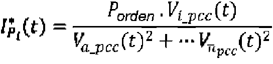
en la que Poder comprende la orden de potencia activa, Vi_pcc(t) comprende la tensión instantánea de la fase para la que se está calculando la corriente de fase activa y Va_pcc(t)2 + — Vnpcc(t)2 representa la suma de los cuadrados de cada una de las medidas de tensión instantánea de las fases de la red eléctrica de CA polifásica. El cálculo de los valores de referencia de corriente activa de este modo también mantiene ventajosamente la sincronización con la red de CA.where Power comprises the active power command, Vi_pcc ( t) comprises the instantaneous voltage of the phase for which the active phase current is being calculated, and Va_pcc ( t)2 + — Vnpcc ( t)2 represents the sum of the squares of each of the instantaneous voltage measurements of the phases of the polyphase AC electrical network. Calculating active current reference values in this way also advantageously maintains synchronization with the AC grid.
Para una red eléctrica de CAque comprende tres fases; a, b y c, los valores de referencia de corriente de fase activa I*pP (t) •'para cada fase, donde i=a, i=b e i=c, se determinan de acuerdo con la siguiente ecuación;For an AC power network comprising three phases; a, b and c, the active phase current reference values I* pP (t) •' for each phase, where i=a, i=bei=c, are determined according to the following equation;
Porden‘ 'â^pcc(t) Porden''â^pcc ( t)
n ai» K_Pj t y v . ( t y v < ty n ai» K_Pj tyv . ( tyv < ty

donde Porden comprende la orden de potencia activa y Va_pcc,Vb_pcc y Vc_pcc comprenden las medidas de tensión instantánea para cada una de las fases.where Porden includes the active power order and Va_pcc,Vb_pcc and Vc_pcc include the instantaneous voltage measurements for each of the phases.
El controlador está configurado de tal manera que los valores de referencia de corriente de fase reactiva se seleccionan de modo que la potencia activa instantánea determinada a partir de los valores de referencia de corriente de fase reactiva es sustancialmente cero. Esto es ventajoso ya que, en base a la teoría de la potencia instantánea, la corriente reactiva mínima sobre las fases necesaria para satisfacer la orden de potencia reactiva se consigue cuando el flujo de potencia activa producido es cero. La potencia activa puede calcularse y, por lo tanto, para un conjunto de valores de referencia de corriente reactiva para cada una de las fases, puede determinarse cuándo la potencia activa es cero (o sustancialmente cero) resultando así la cantidad mínima de corriente para satisfacer la orden de potencia reactiva.The controller is configured such that the reactive phase current reference values are selected such that the instantaneous active power determined from the reactive phase current reference values is substantially zero. This is advantageous since, based on the instantaneous power theory, the minimum reactive current on the phases necessary to satisfy the reactive power order is achieved when the active power flow produced is zero. The active power can be calculated and, therefore, for a set of reactive current reference values for each of the phases, it can be determined when the active power is zero (or substantially zero) thus resulting in the minimum amount of current to satisfy the reactive power order.
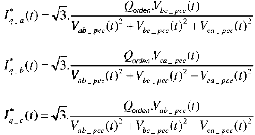
Para una red eléctrica de CA que comprende tres fases, a, b y c, el controlador está configurado de tal manera que los valores de referencia de corriente de fase reactiva donde i=a, b o c para cada fase se calculan como sigue.For an AC mains comprising three phases, a, b and c, the controller is configured in such a way that reactive phase current reference values where i=a, b or c for each phase are calculated as follows.

C Át) = & . Q orden ^ a b _ pee C Át) = & . Q order ^ ab _ pee ))
v,a b_ pee (O2 v be _ pee (t f v ca _ pee ( \ t * y v, a b_ pee (O2 v be _ pee ( tf v ca _ pee ( \ t * y
donde Qorden comprende la orden de potencia reactiva y Vab_pcc,Vbc_pcc y Vca_pcc comprenden las medidas instantáneas de tensión entre la fase a y la fase b, la fase b y la fase c y la fase c y la fase a respectivamente. Para una red eléctrica de CA que tiene tres fases, a, b y c, el controlador está configurado para determinar los valores de referencia de corriente de fase reactiva ^-n<,rh ■m (,-,c-4d0 ) para cad a fase se calculan como siguewhere Qorder comprises the reactive power order and Vab_pcc,Vbc_pcc and Vca_pcc comprise the instantaneous voltage measurements between phase a and phase b, phase b and phase c and phase c and phase a respectively. For an AC mains having three phases, a, b and c, the controller is configured to determine the reactive phase current reference values ^-n<,rh ■ m (, - , c -4 d 0 ) for each to phase are calculated as follows
donde Qorden comprende la orden de potencia reactiva y Vxy_pcc(t) comprende la diferencia entre la tensión instantánea medida de la fase x y la tensión instantánea medida de la fase y, y donde x e y representan las diferentes combinaciones de fases de la red eléctrica de CAque, para una red trifásica, comprenden ab, be y ca. El controlador está configurado para combinar el valor de referencia de corriente de fase activa y el valor de referencia de corriente de fase reactiva correspondiente para cada miembro monofásico a fin de determinar una señal de control para dicho miembro monofásico. Los valores de referencia de corriente activa y reactiva de una fase concreta pueden sumarse.where Qcommand comprises the reactive power command and Vxy_pcc(t) comprises the difference between the measured instantaneous voltage of phase x and the measured instantaneous voltage of phase y, and where x and y represent the different phase combinations of the AC power network, for a three-phase network, they comprise ab, be and ca. The controller is configured to combine the active phase current reference value and the corresponding reactive phase current reference value for each single phase member to determine a control signal for that single phase member. The active and reactive current reference values of a particular phase can be added.
El controlador está configurado para, en base a una determinación del contenido de armónicos de una tensión de entrada al convertidor de fuente de tensión, determinar un valor de referencia de corriente armónica para cada miembro monofásico, el valor de referencia de corriente armónica determinado independientemente del o de cada otro valor de referencia de corriente armónica y que tiene una amplitud sustancialmente equivalente y fase opuesta a dicho contenido de armónicos determinado.The controller is configured to, based on a determination of the harmonic content of an input voltage to the voltage source converter, determine a harmonic current reference value for each single-phase member, the harmonic current reference value determined regardless of the or each other harmonic current reference value and having substantially equivalent amplitude and opposite phase to said determined harmonic content.
El controlador está configurado para combinar el valor de referencia de corriente activa, el valor de referencia de corriente de fase reactiva y el valor de referencia de corriente armónica para cada miembro monofásico a fin de determinar una señal de control para dicho miembro monofásico.The controller is configured to combine the active current reference value, the reactive phase current reference value, and the harmonic current reference value for each single-phase member to determine a control signal for that single-phase member.
El controlador está configurado para determinar una corriente activa instantánea de cada fase de la red eléctrica de CA polifásica, dicho controlador está configurado para determinar una diferencia entre el valor de referencia de corriente activa determinado y las mediciones de corriente activa instantánea correspondientes para cada fase en la determinación de una señal de control para dicho miembro monofásico.The controller is configured to determine an instantaneous active current for each phase of the polyphase AC power network, the controller is configured to determine a difference between the determined active current reference value and the corresponding instantaneous active current measurements for each phase in determining a control signal for said single phase member.
El controlador está configurado para determinar una corriente reactiva instantánea de cada fase de la red eléctrica de CA polifásica, dicho controlador está configurado para determinar una diferencia entre el valor de referencia de corriente reactiva determinado y las mediciones de corriente reactiva instantánea correspondientes para cada fase en la determinación de una señal de control para dicho miembro monofásico.The controller is configured to determine an instantaneous reactive current for each phase of the polyphase AC power network, the controller is configured to determine a difference between the determined reactive current reference value and the corresponding instantaneous reactive current measurements for each phase in determining a control signal for said single phase member.
El controlador está configurado para utilizar un método de multiplicadores de Lagrange; The controller is configured to use a Lagrange multipliers method;
a) para determinar los valores de referencia de corriente activa que satisfacen la orden de potencia activa y que dan lugar a una potencia reactiva mínima; y/oa) to determine the active current reference values that satisfy the active power order and that give rise to a minimum reactive power; I
b) para determinar los valores de referencia de corriente reactiva que satisfacen la orden de potencia reactiva y que dan lugar a una potencia activa mínima.b) to determine the reactive current reference values that satisfy the reactive power order and that give rise to a minimum active power.
El uso de multiplicadores de Lagrange es una técnica matemática ventajosa para determinar los valores de referencia de corriente para cada fase que satisfacen las condiciones de i) cumplir el orden de potencia asociado y ii) minimizar la potencia reactiva para los valores de referencia de corriente activa y minimizar la potencia activa para los valores de referencia de corriente reactiva. Se apreciará que podrían utilizarse otras técnicas matemáticas para determinar el conjunto de valores de referencia de corriente para las fases dadas las condiciones anteriores.The use of Lagrange multipliers is an advantageous mathematical technique to determine the current reference values for each phase that satisfy the conditions of i) fulfilling the associated power order and ii) minimizing the reactive power for the active current reference values. and minimize the active power for the reactive current reference values. It will be appreciated that other mathematical techniques could be used to determine the set of current reference values for the phases given the above conditions.
El controlador está configurado para recibir una medición de la tensión y corriente instantáneas de cada fase de la red eléctrica de CA polifásica y utilizar estas mediciones para calcular la potencia reactiva instantánea resultante debida a los valores de referencia de corriente de fase activa. El controlador está configurado para recibir una medición de la tensión y corriente instantáneas de cada fase de la red eléctrica de CA polifásica y utilizar estas mediciones para calcular la potencia activa instantánea resultante debida a los valores de referencia de corriente de fase reactiva.The controller is configured to receive a measurement of the instantaneous voltage and current from each phase of the polyphase AC mains and use these measurements to calculate the resulting instantaneous reactive power due to active phase current reference values. The controller is configured to receive a measurement of the instantaneous voltage and current from each phase of the polyphase AC mains and use these measurements to calculate the resulting instantaneous active power due to the reactive phase current reference values.
El controlador está configurado para medir la tensión instantánea de cada fase de la red eléctrica de CA polifásica en un punto de acoplamiento común. Cada miembro monofásico puede incluir al menos dos (o más) elementos de fase. Según un segundo ejemplo, se proporciona una red de distribución eléctrica que incluye el convertidor de fuente de tensión del primer aspecto. La red de distribución eléctrica puede incluir además un convertidor conmutado de línea. Según un tercer ejemplo, se proporciona un procedimiento de funcionamiento de un convertidor de fuente de tensión que comprende un primer y un segundo terminal de CC para la conexión a una red eléctrica de CC, una pluralidad de miembros monofásicos conectados cada uno entre el primer y el segundo terminal de CC e incluyendo cada miembro monofásico un elemento de fase, incluyendo cada elemento de fase al menos un elemento de conmutación configurado para interconectar una tensión de Cc y una tensión de CA, pudiendo der conectado un lado de CA de cada elemento de fase a una fase respectiva de una red eléctrica de CA polifásica; el procedimiento comprende los pasos de;The controller is configured to measure the instantaneous voltage of each phase of the polyphase AC mains at a common coupling point. Each single phase member may include at least two (or more) phase elements. According to a second example, an electrical distribution network is provided including the voltage source converter of the first aspect. The electrical distribution network can also include a switched line converter. According to a third example, an operating method of a voltage source converter is provided comprising a first and a second DC terminal for connection to a DC electrical network, a plurality of single-phase members each connected between the first and the second DC terminal and each single phase member including a phase element, each phase element including at least one switching element configured to interconnect a DC voltage and an AC voltage, an AC side of each switching element being capable of being connected phase to a respective phase of a polyphase AC power network; The procedure comprises the steps of;
recibir una orden de potencia activa y una orden de potencia reactiva que comprenda la cantidad deseada de potencia activa y potencia reactiva, respectivamente, que debe ser transferida por el convertidor; recibir una medida de la tensión instantánea de cada fase de una red eléctrica de corriente alterna polifásica;receiving an active power command and a reactive power command comprising the desired amount of active power and reactive power, respectively, to be transferred by the converter; receiving a measurement of the instantaneous voltage of each phase of a polyphase alternating current electrical network;
determinar un valor de referencia de corriente de fase activa y reactiva para cada miembro monofásico que sea independiente del valor de referencia de corriente de fase respectivo o de cada uno de ellos y que defina la corriente que cada miembro monofásico debe extraer de una fase correspondiente de la red eléctrica de corriente alterna o pasar a ella para efectuar los intercambios de potencia activa y potencia reactiva con la red eléctrica de corriente alterna definidos por las órdenes de potencia activa y reactiva; en el que los valores de referencia de corriente de fase activa determinados en función de la orden de potencia activa recibida, las mediciones instantáneas de tensión y una determinación de una potencia reactiva instantánea resultante utilizando dichos valores de referencia de corriente de fase activa; y/odetermining an active and reactive phase current reference value for each single-phase member that is independent of or each respective phase current reference value and that defines the current that each single-phase member must draw from a corresponding phase of the alternating current electrical network or to go to it to carry out the exchanges of active power and reactive power with the alternating current electrical network defined by the active and reactive power orders; wherein active phase current reference values determined based on the received active power command, instantaneous voltage measurements, and a determination of a resulting instantaneous reactive power using said active phase current reference values; I
los valores de referencia de corriente de fase reactiva determinados en función de la orden de potencia reactiva recibida, las mediciones de tensión instantánea y una determinación de una potencia activa instantánea resultante utilizando dichos valores de referencia de corriente de fase reactiva.reactive phase current reference values determined based on the received reactive power command, instantaneous voltage measurements and a determination of a resulting instantaneous active power using said reactive phase current reference values.
A continuación se describen brevemente las realizaciones preferentes de la invención, a modo de ejemplo no limitativo, haciendo referencia a las siguientes figuras:The preferred embodiments of the invention are briefly described below, by way of non-limiting example, with reference to the following figures:
La figura 1 muestra una vista esquemática de una red de transmisión de potencia que incluye un convertidor de fuente de tensión según una primera realización de la invención situado entre las respectivas redes eléctricas de CA y CC;Figure 1 shows a schematic view of a power transmission network including a voltage source converter according to a first embodiment of the invention located between respective AC and DC power networks;
La figura 2 muestra una vista esquemática de un circuito equivalente correspondiente a un lado de CA de la red de transmisión de potencia mostrada en la figura 1 que incluye un controlador;Figure 2 shows a schematic view of an equivalent circuit corresponding to an AC side of the power transmission network shown in Figure 1 including a controller;
La figura 3 muestra una vista esquemática de una primera realización del controlador; yFigure 3 shows a schematic view of a first embodiment of the controller; and
La figura 4 muestra una vista esquemática de una segunda realización del controlador.Figure 4 shows a schematic view of a second embodiment of the controller.
Un convertidor de fuente de tensión según una primera realización de la invención se designa con el número de referencia 10 y se muestra en la figura 1. A voltage source converter according to a first embodiment of the invention is designated by reference numeral 10 and is shown in Figure 1.
El convertidor de fuente de tensión 10 se encuentra dentro de una red de transmisión de potencia 12, y más concretamente interconecta las respectivas redes eléctricas de CA y CC 14, 16. En la realización mostrada, la red eléctrica de CA 14 es una red trifásica a, b, c, aunque las redes eléctricas de CA con menos o más de tres fases también pueden adaptarse mediante convertidores de fuente de tensión según la invención. Además, la red eléctrica de corriente alterna es débil en el sentido de que tiene una alta impedancia equivalente 18 (como se muestra en la figura 2).The voltage source converter 10 is located within a power transmission network 12, and more specifically interconnects the respective AC and DC electrical networks 14, 16. In the embodiment shown, the AC electrical network 14 is a three-phase network. a, b, c, although AC power networks with less or more than three phases can also be adapted by means of voltage source converters according to the invention. Furthermore, the AC mains is weak in the sense that it has a high equivalent impedance 18 (as shown in Figure 2).
Una red eléctrica de CA 14 también puede considerarse débil si tiene poca inercia, es decir, si es susceptible a los cambios de frecuencia, por ejemplo, si se retira un generador de dentro de la red 14. Este tipo de red de baja inercia suele surgir si hay pocos generadores conectados en una línea corta o en una línea muy larga.An AC 14 power grid can also be considered weak if it has low inertia, that is, if it is susceptible to frequency changes, for example if a generator is removed from within the grid 14. This type of low inertia grid is usually arise if there are few generators connected in a short line or in a very long line.
En cualquiera de estos casos, el nivel de potencia activa, es decir, real, que puede intercambiarse con una red eléctrica de CA débil se reduce en comparación con la potencia activa que puede intercambiarse con una red eléctrica de CA fuerte 14, es decir, una red eléctrica de CA 14 que tiene una impedancia equivalente mucho menor y/o una inercia mucho mayor. El convertidor de fuente de tensión 10 de la invención es, no obstante, operable tanto con una red eléctrica de CA débil como fuerte 14.In any of these cases, the level of active, i.e. real, power that can be exchanged with a weak AC mains is reduced compared to the active power that can be exchanged with a strong AC mains 14, that is, an AC 14 mains that has a much lower equivalent impedance and/or a much higher inertia. The voltage source converter 10 of the invention is, however, operable on both a weak and a strong AC mains 14.
En la realización mostrada, el convertidor de fuente de tensión 10 está conectado con la red eléctrica de CA 14 mediante un transformador 20 que da lugar a una impedancia de transformador que está representada en el circuito equivalente mostrado en la Figura 2 por un inductor 21. No es necesario que el convertidor de fuente de tensión 10 esté siempre conectado a la red eléctrica de CA 14 a través de un transformador 20. En cualquier caso, la conexión entre el convertidor de fuente de tensión 10 y la red eléctrica de CA 14 define un punto de acoplamiento común (PCC) 22 entre ambas.In the shown embodiment, the voltage source converter 10 is connected to the AC mains 14 via a transformer 20 which results in a transformer impedance which is represented in the equivalent circuit shown in Figure 2 by an inductor 21. The voltage source converter 10 need not always be connected to the AC mains 14 via a transformer 20. In any case, the connection between the voltage source converter 10 and the AC mains 14 defines a common coupling point (PCC) 22 between both.
El propio convertidor de fuente de tensión 10 incluye un primer y un segundo terminal de CC 24, 26 que, en uso, están conectados a la red eléctrica de CC 16. El convertidor de fuente de tensión 10 también incluye tres miembros monofásicos 28 (sólo uno de los cuales se muestra esquemáticamente en la figura 1). Se puede considerar que cada miembro monofásico comprende dos porciones de miembro que se conectan a los respectivos terminales de CC primero y segundo 24, 26 con su otro extremo de la porción de miembro conectado a un terminal de CA 34 para una fase asociada. Cada porción de miembro monofásico incluye un elemento de fase 30 que, en la realización mostrada, incluye un único elemento de conmutación 32 que está configurado para interconectar una tensión Vcc CC de la red eléctrica de CC 16 con una tensión de CA de la red eléctrica de CA 14. Más concretamente, un lado de CA 34 de cada elemento de fase 30 está conectado en uso a una fase a, b, c respectiva de la red eléctrica de CA 14, a través de la impedancia del transformador, es decir, el inductor equivalente 21, y cada miembro monofásico 28 está conectado entre los terminales de CC primero y segundo 24, 26. En otras realizaciones de la invención (no mostradas), uno o más de los elementos de fase 30 pueden incluir más de un elemento de conmutación 32, como al menos dos elementos de conmutación, y en otras realizaciones, uno o más de los elementos de fase 30 pueden incluir adicionalmente un dispositivo de almacenamiento de energía, por ejemplo en forma de condensador. Los expertos en la materia apreciarán que puede utilizarse una estructura de medio puente y/o de puente completo. Además, cada miembro 28 o, más particularmente, porción de miembro, puede comprender al menos un elemento de fase o una pluralidad de elementos de fase que forman una cadena de elementos de fase conectados en serie, como sabrán los expertos en la materia.The voltage source converter 10 itself includes first and second DC terminals 24, 26 which, in use, are connected to the DC mains 16. The voltage source converter 10 also includes three single-phase members 28 (only one of which is shown schematically in Figure 1). Each single phase member can be considered to comprise two member portions connecting to respective first and second DC terminals 24, 26 with its other end of the member portion connected to an AC terminal 34 for an associated phase. Each single phase member portion includes a phase element 30 which, in the embodiment shown, includes a single switching element 32 that is configured to interconnect a DC mains voltage Vdc DC 16 with an AC mains voltage of AC 14. More specifically, one AC side 34 of each phase element 30 is connected in use to a respective phase a,b,c of the AC mains 14, through the impedance of the transformer, i.e., the equivalent inductor 21, and each single phase member 28 is connected between the first and second DC terminals 24, 26. In other embodiments of the invention (not shown), one or more of the phase elements 30 may include more than one element switching element 32, as at least two switching elements, and in other embodiments, one or more of the phase elements 30 may additionally include an energy storage device, for example in the form of a capacitor. Those skilled in the art will appreciate that a half bridge and/or full bridge framework can be used. Furthermore, each member 28 or, more particularly, member portion, may comprise at least one phase element or a plurality of phase elements forming a chain of series-connected phase elements, as will be known to those skilled in the art.
El convertidor de fuente de tensión 10 también incluye un controlador 36, como se muestra esquemáticamente en la figura 2 y con más detalle en las figuras 3 y 4. El controlador 36 puede formar parte de un sistema de control para controlar el convertidor 10. Por lo tanto, otros parámetros, como las mediciones y/u órdenes utilizadas para controlar el funcionamiento del convertidor 10, pueden ser determinados por partes del sistema de control que no se muestran en la figura 2.The voltage source converter 10 also includes a controller 36, as shown schematically in Figure 2 and in more detail in Figures 3 and 4. The controller 36 may form part of a control system to control the converter 10. For Therefore, other parameters, such as the measurements and/or commands used to control the operation of the converter 10, may be determined by parts of the control system that are not shown in Figure 2.
El controlador 36 comprende un bloque 38 de determinación de la corriente de fase de referencia que está configurado para determinar una corriente de referencia para cada una de las fases a fin de satisfacer una demanda de potencia, como se describirá con más detalle a continuación con referencia a las figuras 3 y 4. Las corrientes de referencia para cada fase se calculan independientemente unas de otras y también independientemente para una orden de potencia activa y otra orden de potencia reactiva. Esto permite modificar al menos una corriente de fase tomada de la red eléctrica de CA polifásica sin afectar a las otras corrientes de fase. Esto proporciona al convertidor de fuente de tensión la capacidad de extraer fácilmente una amplia gama de combinaciones de corrientes de fase de la red eléctrica de CA polifásica.The controller 36 comprises a reference phase current determination block 38 that is configured to determine a reference current for each of the phases to satisfy a power demand, as will be described in more detail below with reference to to figures 3 and 4. The reference currents for each phase are calculated independently from each other and also independently for an active power order and another reactive power order. This allows modifying at least one phase current taken from the polyphase AC mains without affecting the other phase currents. This gives the voltage source converter the ability to easily draw a wide range of phase current combinations from the polyphase AC mains.
Las corrientes de referencia para cada fase, IrefA, IrefB, IrefC, determinadas por el bloque 38 se suministran a los respectivos bloques de control de fase individual 40a, 40b y 40c. Los bloques de control de fase 40a, 40b, 40c también reciben una medición de la tensión instantánea, Va, Vb, Vc, de cada fase de la red en el PCC 22 y la corriente instantánea de cada fase, Ia, Ib, Ic. Utilizando estos valores, cada bloque de control de fase 40a, 40b, 40c determina una señal de control de fase para cada fase, independientemente de las señales de control de fase para cada una de las otras fases. Las señales de control de fase Vconva, Vconvb, Vconvc para cada fase se suministran al convertidor 10 o, más particularmente, a otra parte del sistema de control. Así pues, puede utilizarse un módulo de control de conmutación (no mostrado), como sabrán los expertos en la materia, para conmutar los elementos de conmutación 32 a fin de generar o sintetizar las tensiones determinadas por las señales de control de fase Vconva, Vconvb, Vconvc.The reference currents for each phase, IrefA, IrefB, IrefC, determined by block 38 are supplied to the respective individual phase control blocks 40a, 40b and 40c. The phase control blocks 40a, 40b, 40c also receive a measurement of the instantaneous voltage, Va, Vb, Vc, of each phase of the network at the PCC 22 and the instantaneous current of each phase, Ia, Ib, Ic. Using these values, each phase control block 40a, 40b, 40c determines a phase control signal for each phase, independently of the phase control signals for each of the other phases. The phase control signals Vconva, Vconvb, Vconvc for each phase are supplied to the converter 10 or, more particularly, to another part of the control system. Thus, a switching control module (not shown) may be used, as will be known to those skilled in the art, to switch the switching elements. switching 32 in order to generate or synthesize the voltages determined by the phase control signals Vconva, Vconvb, Vconvc.
La figura 3 muestra, esquemáticamente, el controlador 36 y, en particular, una realización del bloque 38 de determinación de la corriente de fase de referencia. El controlador 36 está dividido en tres secciones: una primera sección 40, una segunda sección 42 y una tercera sección 44. Se apreciará que la delimitación del controlador en estas secciones puede ser a efectos ilustrativos y puede no reflejar una implementación práctica del controlador 36. La primera sección 40 muestra generalmente un bucle de control externo 41 del controlador, que está configurado para determinar, entre otros parámetros, un orden de potencia activa, Porden. La orden de potencia activa comprende una cantidad de potencia activa o real que el convertidor debe pasar entre las redes eléctricas de CA y CC 14, 16. En el caso de que el convertidor funcione como inversor y, por lo tanto, convierta la energía de CC en energía de CA, la orden de potencia activa puede ser la potencia de CC disponible. La orden de potencia, en general, comprende la cantidad deseada de potencia eléctrica que debe transferirse a y/o desde la red de CA 14 en cualquier momento e "inyectarse" en el PCC 22.Figure 3 schematically shows the controller 36 and, in particular, an embodiment of the block 38 for determining the reference phase current. Controller 36 is divided into three sections: a first section 40, a second section 42, and a third section 44. It will be appreciated that the delineation of the controller in these sections may be for illustrative purposes and may not reflect a practical implementation of controller 36. The first section 40 generally shows an external control loop 41 of the controller, which is configured to determine, among other parameters, an active power command, Porden. The active power command comprises an amount of active or real power that the converter must pass between the AC and DC electrical networks 14, 16. In the event that the converter functions as an inverter and therefore converts power from DC on AC power, the active power order can be the available DC power. The power command, in general, comprises the desired amount of electrical power that is to be transferred to and/or from the AC network 14 at any time and "injected" into the PCC 22.
La primera sección 40 también determina una orden de potencia reactiva o potencia imaginaria, Qorden. La orden de potencia reactiva comprende una cantidad de potencia reactiva que el convertidor debe intercambiar entre las fases de las redes eléctricas de CA 14. En un sistema práctico, las pérdidas y la baja potencia de la red de CA provocan variaciones en la tensión de salida del convertidor para distintas órdenes de potencia activa. La orden de potencia reactiva puede seleccionarse para garantizar que la salida de tensión del convertidor 10 sea sustancialmente constante, pero sin contribuir al flujo de potencia real.The first section 40 also determines a reactive power or imaginary power command, Qcommand. The reactive power command comprises an amount of reactive power that the drive must exchange between the phases of the AC mains 14. In a practical system, losses and low power of the AC mains cause variations in the output voltage of the converter for different orders of active power. The reactive power command can be selected to ensure that the voltage output of the converter 10 is substantially constant, but does not contribute to the actual power flow.
El bloque de cálculo de la orden de potencia 41 determina la orden de potencia activa Porden y la orden de potencia reactiva Qorden basándose en al menos algunos de los valores determinados por el bloque de demanda 46, el bloque de medición 48 y la realimentación 50. El bloque de demanda 46 proporciona una demanda de tensión continua, Vcc, una demanda de tensión alterna, VCa, una demanda de potencia continua, Pcc, y una demanda de potencia reactiva nominal, Qnominal. El bloque de medidas 48 proporciona una medida de la tensión continua y una medida de la corriente continua. El bloque de demanda 46 puede calcular o recibir los valores de demanda de una parte diferente del sistema de control. Las mediciones pueden ser realizadas por el bloque de medición 48 o recibidas de otra parte del sistema de control. La realimentación comprende la potencia activa instantánea Ppcc y la potencia reactiva instantánea Qpcc determinadas a partir de las medidas de tensión y corriente instantáneas en el pCc 22 y como se describirá más adelante en relación con la segunda etapa 42.The power command calculation block 41 determines the active power command Pden and the reactive power command Qcommand based on at least some of the values determined by the demand block 46, the measurement block 48 and the feedback 50. The demand block 46 provides a direct voltage demand, Vcc, an alternating voltage demand, VCa, a continuous power demand, Pcc, and a nominal reactive power demand, Qnominal. Measurement block 48 provides a DC voltage measurement and a DC current measurement. The demand block 46 may calculate or receive the demand values from a different part of the control system. The measurements may be made by the measurement block 48 or received from another part of the control system. The feedback comprises the instantaneous active power Ppcc and the instantaneous reactive power Qpcc determined from the instantaneous voltage and current measurements at p C c 22 and as will be described later in connection with the second stage 42.
El controlador 36 se ocupa en particular de cómo se implementa la orden de potencia activa y la orden de potencia reactiva, que es realizada por las secciones segunda y tercera 42, 44.The controller 36 is concerned in particular with how the active power command and the reactive power command are implemented, which is performed by the second and third sections 42, 44.
La segunda sección 42 comprende cuatro bloques de cálculo 52, 54, 56, 58. Cada uno de los bloques de cálculo 52, 54, 56, 58 recibe una medida de la tensión instantánea de cada fase, Va_pcc, Vb_pcc y Vc_pcc en el punto de acoplamiento común 22 y una medida de la corriente de cada fase, Ia, Ib e Ic en el punto de acoplamiento común 22. Los bloques de cálculo comprenden; un bloque de cálculo de potencia activa instantánea 52, un bloque de cálculo de potencia reactiva instantánea 54, un bloque de cálculo de corriente activa instantánea 56 y un bloque de cálculo de corriente reactiva instantánea 58.The second section 42 comprises four calculation blocks 52, 54, 56, 58. Each of the calculation blocks 52, 54, 56, 58 receives a measurement of the instantaneous voltage of each phase, Va_pcc, Vb_pcc and Vc_pcc at point common coupling point 22 and a measurement of the current of each phase, Ia, Ib and Ic at the common coupling point 22. The calculation blocks comprise; an instantaneous active power calculation block 52, an instantaneous reactive power calculation block 54, an instantaneous active current calculation block 56 and an instantaneous reactive current calculation block 58.
El bloque 52 determina la potencia activa instantánea Ppcc(t) mediante la siguiente ecuación;Block 52 determines the instantaneous active power Ppcc(t) by the following equation;

donde Vx_pcc(t) comprende la tensión instantánea medida para una de las fases a, b o c a tierra e Ix(t) comprende la corriente medida para una de las fases a, b o c. La tensión instantánea medida para una de las fases a, b o c comprende;where Vx_pcc(t) comprises the instantaneous voltage measured for one of the phases a, b or c to ground and Ix(t) comprises the current measured for one of the phases a, b or c. The instantaneous voltage measured for one of the phases a, b or c comprises;

donde Va, Vb y Vc son el valor eficaz de las tensiones de fase Vx_pcc y, para una red trifásica, 0=120°.where Va, Vb and Vc are the effective value of the phase voltages Vx_pcc and, for a three-phase network, 0=120°.
El bloque 54 determina la potencia reactiva instantánea Qpcc(t) mediante la siguiente ecuación;Block 54 determines the instantaneous reactive power Qpcc(t) by the following equation;
Q ? jn = ^ . ( v hc r( t) . ia ( t ) + vca rcc(í) . ib ( o vab Bj t u c (0) what? jn = ^ . ( v hc r ( t) . ia ( t ) + vca rcc ( í) . ib ( o vab Bj tuc ( 0)
donde Vxy_pcc(t) comprende la diferencia entre la tensión instantánea medida de la fase x y la tensión instantánea medida de la fase y, y donde x e y representan las diferentes combinaciones de fases de la red eléctrica de CA, que en esta realización comprende las fases a, b y c (lo que hace que xy comprenda ab, be, ca).where Vxy_pcc(t) comprises the difference between the measured instantaneous voltage of phase x and the measured instantaneous voltage of phase y, and where x and y represent the different phase combinations of the AC power grid, which in this embodiment comprises phases a , b and c (which makes xy comprise ab, be, ca).
El bloque 56 determina la corriente activa instantánea para cada fase; Ip_a(t), Ip_b(t), Ip_c(t) de acuerdo con la siguiente ecuación;Block 56 determines the instantaneous active current for each phase; Ip_a(t), Ip_b(t), Ip_c(t) according to the following equation;

El bloque 56 determina la corriente reactiva instantánea para cada fase; Iq_a(t), Iq_b(t), Iq_c(t) de acuerdo con la siguiente ecuación;Block 56 determines the instantaneous reactive current for each phase; Iq_a(t), Iq_b(t), Iq_c(t) according to the following equation;

El bloque de cálculo de potencia activa instantánea 52 y el bloque de cálculo de potencia reactiva instantánea 54 proporcionan su salida como realimentación 50 a la primera sección 40. El bloque de cálculo de corriente activa instantánea 56 y el bloque de cálculo de corriente reactiva instantánea 58 proporcionan su salida a la tercera sección 44.The instantaneous active power calculation block 52 and the instantaneous reactive power calculation block 54 provide their output as feedback 50 to the first section 40. The instantaneous active current calculation block 56 and the instantaneous reactive current calculation block 58 provide their output to the third section 44.
Así, la tercera sección 44 recibe la orden de potencia activa Porden y la orden de potencia reactiva Qorden determinadas por un bucle de control externo 41 representado por la primera sección 40 y la potencia activa instantánea y la potencia reactiva instantánea determinadas por la sección 42. Además, la tercera sección 44 también recibe las mediciones instantáneas de tensión para cada una de las fases Va_pcc, Vb_pcc y Vc_pcc determinadas a partir del PCC 22.Thus, the third section 44 receives the active power order Pden and the reactive power order Qorder determined by an external control loop 41 represented by the first section 40 and the instantaneous active power and instantaneous reactive power determined by the section 42. Furthermore, the third section 44 also receives the instantaneous voltage measurements for each of the phases Va_pcc, Vb_pcc and Vc_pcc determined from the PCC 22.
La tercera sección 44 comprende un generador de referencia de corriente activa instantánea 60 y un generador de referencia de corriente reactiva instantánea 62.The third section 44 comprises an instantaneous active current reference generator 60 and an instantaneous reactive current reference generator 62.
Los generadores de referencia de corriente 60, 62 determinan cómo implementar las órdenes de potencia activa y reactiva determinadas en la primera sección 40. Se apreciará que con el control independiente de cada uno de los miembros de fase 28 del convertidor 10, hay muchas permutaciones de valores de corriente de fase sobre las múltiples fases que satisfarían la orden de potencia. La selección de las corrientes de fase deseadas para implementar la orden de potencia se realiza mediante los generadores de referencia de corriente 60, 62. Se ha comprobado que una selección particular de las corrientes de fase para implementar la orden de potencia puede conducir a un convertidor y un esquema de control eficientes, así como a un convertidor capaz de funcionar de forma fiable a pesar de perturbaciones graves en la red de CA 14. Esto es ventajoso si la red de CA 14 es débil. Se ha determinado que los valores instantáneos mínimos de las corrientes de fase para satisfacer la orden de potencia provocarían la menor variación de tensión en toda la red conectada de CA en condiciones para las que es importante la estabilidad de la tensión.The current reference generators 60, 62 determine how to implement the active and reactive power commands determined in the first section 40. It will be appreciated that with independent control of each of the phase members 28 of the converter 10, there are many permutations of phase current values over the multiple phases that would satisfy the power order. The selection of the desired phase currents to implement the power command is performed by the current reference generators 60, 62. It has been found that a particular selection of the phase currents to implement the power command can lead to a converter and an efficient control scheme, as well as a converter capable of operating reliably despite severe disturbances in the AC network 14. This is advantageous if the AC network 14 is weak. It has been determined that the minimum instantaneous values of the phase currents to satisfy the power order would cause the smallest voltage variation across the entire connected AC network under conditions where voltage stability is important.
El generador de referencia de corriente activa 60 recibe la orden de potencia activa Porden y las medidas de tensión instantánea para cada una de las fases Va_pcc, Vb_pcc y Vc_pcc. Los valores de referencia de la corriente activa para cada fase se determinan para minimizar la corriente total sobre el número total de fases. Esto se consigue seleccionando valores de referencia de corriente activa que minimicen la potencia reactiva en el PCC 22. En particular, los valores de referencia de corriente activa se seleccionan de forma que se satisfaga la orden de potencia activa Porden sin que se suministre potencia reactiva en el PCC 22. Esto puede determinarse mediante un procedimiento de optimización, como el método de Legrange, que será conocido por los expertos en la materia. Se ha determinado que las siguientes ecuaciones dan como resultado dicho conjunto de valores de referencia de corriente activa, I*p_a, I*p_b, I*p_c;The active current reference generator 60 receives the active power order Porden and the instantaneous voltage measurements for each of the phases Va_pcc, Vb_pcc and Vc_pcc. The active current reference values for each phase are determined to minimize the total current over the total number of phases. This is achieved by selecting active current reference values that minimize the reactive power in the PCC 22. In particular, the active current reference values are selected such that the active power command Porden is satisfied without reactive power being supplied in the PCC 22. This can be determined by an optimization procedure, such as the Legrange method, which will be known to those skilled in the art. It has been determined that the following equations result in said set of active current reference values, I*p_a, I*p_b, I*p_c;
porden V a _ pcc ( v * t) f p order V a _ pcc ( v * t) f
C A O va_pj t )2+k _,j í )2+v^ c(o 2 CAO va_pj t ) 2 + k _, j ) 2 + v ^ c ( or 2
^orden E ' r _ pcc ( 9 ^order E ' r _ pcc ( 9
C .b(o = va_pJ02+vb_pcc(t)2+vc_pj t )2 C .b ( o = va_pJ02+vb_pcc ( t)2+vc_pj t )2
Porden V c _ pee V (t) ' P order V c _ pee V ( t) '
C At) = :C At) = :
M f vib _ pee ( t r K_pj t y M f vi b _ pee ( tr K_pj ty
Se apreciará que mientras en esta realización la selección de los valores de referencia de corriente activa se basa en proporcionar una potencia reactiva sustancialmente nula en el PCC 22, en otras realizaciones, el bloque está configurado para mantener la potencia reactiva en el PCC producida por la selección de los valores de referencia de corriente activa por debajo de un umbral "reactivo". Por lo tanto, las ecuaciones anteriores se derivan en base a cálculos de potencia reactiva igual a cero, aunque el controlador puede estar configurado para utilizar un umbral reactivo predeterminado y seleccionar los valores de referencia de corriente activa que proporcionan potencia reactiva por debajo de dicho umbral reactivo. Se apreciará que, en cualquier caso, la determinación de los valores de referencia de corriente activa se basa en una determinación de la potencia reactiva (ya sea limitada a cero o por debajo de un umbral) que resultaría del uso de los valores de referencia de corriente activa.It will be appreciated that while in this embodiment the selection of the active current reference values is based on providing substantially zero reactive power at the PCC 22, in other embodiments the block is configured to maintain the reactive power at the PCC produced by the selection of active current reference values below a "reactive" threshold. Therefore, the above equations are derived based on zero reactive power calculations, although the controller may be configured to use a predetermined reactive threshold and select active current reference values that provide reactive power below that threshold. reagent. It will be appreciated that, in any case, the determination of the active current reference values is based on a determination of the reactive power (either limited to zero or below a threshold) that would result from the use of the active current reference values. active current.
El generador de referencia de corriente reactiva 62 recibe la orden de potencia reactiva Qorden y las medidas de tensión instantáneas para cada una de las fases Va_pcc, Vb_pcc y Vc_pcc. Los valores de referencia de corriente reactiva para cada fase se determinan para minimizar la corriente total sobre el número total de fases, satisfaciendo al mismo tiempo la orden de potencia reactiva. Esto se consigue seleccionando valores de referencia de corriente reactiva que minimicen la potencia activa en el PCC 22 hasta cero o casi cero. En particular, los valores de referencia de la corriente reactiva se seleccionan de forma que se satisfaga la orden de potencia reactiva Qorden sin que se suministre potencia activa en el PCC 22. Esto puede determinarse mediante un procedimiento de optimización, como el método de Lagrange, que será conocido por los expertos en la materia. Se ha determinado que las siguientes ecuaciones dan como resultado dicho conjunto de valores de referencia de corriente reactiva, I*q_a, I*q_b, I*q_c;The reactive current reference generator 62 receives the reactive power order Qorder and the instantaneous voltage measurements for each of the phases Va_pcc, Vb_pcc and Vc_pcc. The reactive current reference values for each phase are determined to minimize the total current over the total number of phases, while satisfying the reactive power order. This is achieved by selecting reactive current reference values that minimize the active power at PCC 22 to zero or near zero. In particular, the reactive current reference values are selected such that the reactive power command Qcommand is satisfied without active power being supplied at the PCC 22. This can be determined by an optimization procedure, such as the Lagrange method, which will be known to those skilled in the art. It has been determined that the following equations result in said set of reactive current reference values, I*q_a, I*q_b, I*q_c;

Se apreciará que mientras en esta realización la selección de los valores de referencia de corriente reactiva se basa en proporcionar una potencia activa sustancialmente nula en el PCC 22, en otras realizaciones, el bloque puede configurarse para mantener la potencia activa en el PCC producida por la selección de los valores de referencia de corriente reactiva por debajo de un umbral. Así, las ecuaciones anteriores se derivan en base a cálculos de potencia activa igual a cero, aunque el controlador puede estar configurado para utilizar un umbral activo predeterminado y seleccionar los valores de referencia de corriente reactiva que proporcionan potencia activa por debajo de dicho umbral activo. Se apreciará que, en cualquier caso, la determinación de los valores de referencia de corriente reactiva se basa en una determinación de la potencia activa (ya sea limitada a cero o por debajo de un umbral) que resultaría del uso de los valores de referencia de corriente reactiva.It will be appreciated that while in this embodiment the selection of the reactive current reference values is based on providing substantially zero active power at the PCC 22, in other embodiments, the block may be configured to maintain the active power at the PCC produced by the selection of reactive current reference values below a threshold. Thus, the above equations are derived based on zero active power calculations, although the controller may be configured to use a predetermined active threshold and select reactive current reference values that provide active power below said active threshold. It will be appreciated that, in any case, the determination of the reactive current reference values is based on a determination of the active power (whether limited to zero or below a threshold) that would result from the use of the reference values of reactive current.
La selección de estos valores de referencia de corriente activa y reactiva para satisfacer las órdenes de potencia activa y reactiva es ventajosa. Puede demostrarse que, utilizando los valores de referencia de corriente activa, el convertidor 10 sólo transfiere potencia activa para satisfacer la orden de potencia activa. Asimismo, puede demostrarse que, utilizando los valores de referencia de corriente reactiva, el convertidor 10 sólo transfiere potencia reactiva para satisfacer la orden de potencia reactiva. Se ha comprobado que esto mejora la estabilidad del convertidor.The selection of these active and reactive current reference values to satisfy the active and reactive power commands is advantageous. It can be shown that, using the active current reference values, the converter 10 only transfers active power to satisfy the active power command. Also, it can be shown that, using the reactive current reference values, the converter 10 only transfers reactive power to satisfy the reactive power command. This has been found to improve the stability of the converter.
Los valores de referencia de corriente activa comprenden así un valor de referencia de corriente activa determinado independientemente para cada fase a, b, c. Los valores de referencia de corriente reactiva comprenden así un valor de referencia de corriente reactiva determinado independientemente para cada fase a, b, c.The active current reference values thus comprise an independently determined active current reference value for each phase a, b, c. The reactive current reference values thus comprise an independently determined reactive current reference value for each phase a, b, c.
El bloque de diferencia 64 proporciona una diferencia entre el valor de referencia de corriente activa determinado y un correspondiente valor de corriente activa instantánea para la fase correspondiente. El bloque de diferencia 66 proporciona una diferencia entre el valor de referencia de corriente reactiva determinado y un correspondiente valor de corriente reactiva instantánea para la fase correspondiente. Los bloques de diferencia 64, 66 proporcionan esta diferencia para cada fase.The difference block 64 provides a difference between the determined active current reference value and a corresponding instantaneous active current value for the corresponding phase. The difference block 66 provides a difference between the determined reactive current reference value and a corresponding instantaneous reactive current value for the corresponding phase. The difference blocks 64, 66 provide this difference for each phase.
Con este procedimiento, el convertidor VSC 10 mantiene su sincronización con la red de CA 14 de forma similar al funcionamiento de una máquina síncrona. En un sistema de CA, las máquinas síncronas mantienen el sincronismo mediante la transferencia de potencia transitoria y la reacción de estas corrientes en el inducido, para alinear continuamente el ángulo del rotor. En este controlador, la transferencia de potencia implica una corriente, que es desconocida y viene determinada por la red de interconexión en lugar de utilizar un bucle de enganche de fase (PLL). Es sabido que la potencia reactiva no contribuye a la potencia de la red y, de hecho, ajustará únicamente la tensión, que a su vez provocará un ajuste en la corriente, manteniendo la potencia en el nivel establecido. De este modo, el controlador puede mantener la sincronización con la red de CA 14.With this procedure, the VSC 10 maintains its synchronization with the AC network 14 similar to the operation of a synchronous machine. In an AC system, synchronous machines maintain synchronism by transient power transfer and the reaction of these armature currents to continuously align the rotor angle. In this controller, power transfer involves a current, which is unknown and is determined by the interconnection network instead of using a phase locked loop (PLL). It is known that the reactive power does not contribute to the power of the network and, in fact, it will only adjust the voltage, which in turn will cause an adjustment in the current, keeping the power at the set level. In this way, the controller can maintain synchronization with the AC grid 14.
Las diferencias "activas" del bloque de diferencias 64 se proporcionan a un bloque de instrucciones de fase activa 68, que se muestra como un único bloque pero que comprende un bloque para cada fase. Asimismo, las diferencias "reactivas" del bloque de diferencias 65 se proporcionan a un bloque de instrucciones de fase reactiva 70, que también comprende un bloque para cada fase. Estos bloques de instrucciones para cada fase se realizan como un controlador Proporcional-Integral (PI), un controlador Proporcional-Resonante (PR) o cualquier otro controlador apropiado. Los bloques de instrucciones 68, 70, comprenden tres bloques de instrucciones de fase activa y tres bloques de instrucciones de fase reactiva. Los bloques 68 y 70 están configurados para determinar los cambios en cada una de las diferencias a lo largo del tiempo y generar una tensión de referencia del convertidor para cada fase y para cada una de las órdenes de potencia activa y reactiva.The "active" differences from the difference block 64 are provided to an active phase instruction block 68, shown as a single block but comprising one block for each phase. Likewise, the "reactive" differences from the difference block 65 are provided to a reactive phase instruction block 70, which also comprises a block for each phase. These instruction blocks for each phase are realized as a Proportional-Integral (PI) controller, a Proportional-Resonant (PR) controller, or any other appropriate controller. Instruction blocks 68, 70 comprise three active phase instruction blocks and three reactive phase instruction blocks. Blocks 68 and 70 are configured to determine the changes in each of the differences over time and generate a converter reference voltage for each phase and for each of the active and reactive power commands.
Un bloque sumador 72 recibe las tensiones de referencia del convertidor para las tres fases para el orden de potencia activa y las tensiones de referencia del convertidor para las tres fases para el orden de potencia reactiva. El bloque 72 también recibe las medidas instantáneas de tensión para cada una de las fases Va_pcc, Vb_ pcc y Vc_pcc. El bloque sumador, para cada fase, suma la tensión de referencia del convertidor activo correspondiente, la tensión de referencia del convertidor reactivo correspondiente y la medida de tensión instantánea correspondiente. El resultado de esta suma proporciona las señales de control de fase Vconva, Vconvb, Vconvc para cada fase, que son utilizadas por otra parte del sistema de control. La otra parte del sistema de control puede controlar un esquema de conmutación de los elementos de conmutación 32 en el miembro que corresponde a la fase de la señal de control de fase, por ejemplo.An adder block 72 receives the converter reference voltages for the three phases for the active power order and the converter reference voltages for the three phases for the reactive power order. Block 72 also receives the instantaneous voltage measurements for each of the phases Va_pcc, Vb_pcc and Vc_pcc. The adder block, for each phase, adds the reference voltage of the corresponding active converter, the reference voltage of the corresponding reactive converter and the corresponding instantaneous voltage measurement. The result of this addition provides the phase control signals Vconva, Vconvb, Vconvc for each phase, which are used by another part of the control system. The other part of the control system can control a switching scheme of the switching elements 32 in the member corresponding to the phase of the phase control signal, for example.
La figura 4 muestra, esquemáticamente, el controlador 36 y, en particular, una segunda realización del bloque 38 de determinación de la corriente de fase de referencia. De forma similar a la primera realización, el controlador 36 está dividido en tres secciones: la primera sección 40, la segunda sección 42 y la tercera sección 44. Se apreciará que la delimitación del controlador en estas secciones puede ser a efectos ilustrativos y puede no reflejar una implementación práctica del controlador 36. Como los números de referencia se han utilizado para las mismas partes y por lo tanto sólo se describirán las diferencias entre la segunda realización y la primera realización.Figure 4 schematically shows the controller 36 and, in particular, a second embodiment of the block 38 for determining the reference phase current. Similar to the first embodiment, controller 36 is divided into three sections: first section 40, second section 42, and third section 44. It will be appreciated that the delineation of the controller into these sections may be for illustrative purposes and may not. reflect a practical implementation of the controller 36. As the reference numerals have been used for the same parts and therefore only the differences between the second embodiment and the first embodiment will be described.
La primera sección 40 es idéntica a la primera realización. La segunda sección 42, en esta realización, es sustancialmente idéntica excepto que el bloque de cálculo de corriente activa instantánea 56 y el bloque de cálculo de corriente reactiva instantánea 58 están ausentes. De este modo, la corriente activa y reactiva instantánea no pasa a la tercera sección 44.The first section 40 is identical to the first embodiment. The second section 42, in this embodiment, is substantially identical except that the instantaneous active current calculation block 56 and the instantaneous reactive current calculation block 58 are absent. In this way, the instantaneous active and reactive current does not pass to the third section 44.
La tercera sección 44 incluye el generador de referencia de corriente activa instantánea 60 y el generador de referencia de corriente reactiva instantánea 62. Los generadores 60 y 62 funcionan como se ha explicado en relación con la primera realización.The third section 44 includes the instantaneous active current reference generator 60 and the instantaneous reactive current reference generator 62. The generators 60 and 62 operate as explained in connection with the first embodiment.
La tercera sección 44 difiere en que un bloque sumador 74 suma, para cada fase individual, el valor de referencia de corriente activa y el valor de referencia de corriente reactiva. A continuación, un bloque de diferencias 76 calcula una diferencia, para cada fase individual, entre los valores de referencia de corriente (activa y reactiva) sumados y una medida de la corriente de la fase correspondiente en el PCC 22.The third section 44 differs in that an adder block 74 adds, for each individual phase, the active current reference value and the reactive current reference value. A difference block 76 then calculates a difference, for each individual phase, between the summed (active and reactive) current reference values and a measurement of the corresponding phase current at the PCC 22.
La tercera sección 44 incluye tres bloques de instrucción de fase 78, que se muestra como un solo bloque pero comprende un bloque para cada fase. Cada bloque de instrucción de fase recibe la diferencia correspondiente a su fase, del bloque 76, y una medida de la tensión de fase correspondiente en el PCC 22. Cada bloque de instrucción de fase 76 genera entonces las señales de control de fase Vconva,b,c para su fase, que es utilizada por otra parte del sistema de control, como se ha comentado anteriormente. Estos bloques de instrucciones 76 pueden ser incorporados como un controlador Proporcional-Resonante (PR) o control mediante modos deslizantes de tiempo discreto (DSMC), que será conocido por los expertos en la materia, o por cualquier otro controlador apropiado. Otro aspecto del controlador 36 puede ser la compensación de elementos armónicos. En particular, midiendo o prediciendo las inyecciones de corriente armónica, el controlador 36 está configurado para compensar las distorsiones causadas por transformadores saturados o por convertidores LCC cercanos. Esto podría lograrse mediante un bloque de control de armónicos (no mostrado) que aplica una modificación a las corrientes de fase determinadas anteriormente para incluir un componente armónico al mismo nivel de amplitud pero en oposición de fase, de forma que se anule cualquier distorsión armónica y se mejore la calidad de la tensión de conmutación. Esto puede ayudar a los convertidores LCC a recuperarse con menos fallos de conmutación. En este caso, puede considerarse que el convertidor VSC 10 actúa como un filtro activo además de intercambiar potencia activa y reactiva.The third section 44 includes three phase instruction blocks 78, shown as a single block but comprising one block for each phase. Each phase command block receives the difference corresponding to its phase, from block 76, and a measurement of the corresponding phase voltage at PCC 22. Each phase command block 76 then generates the phase control signals Vconva,b ,c for its phase, which is used by another part of the control system, as discussed above. These instruction blocks 76 may be incorporated as a Proportional-Resonant (PR) controller or Discrete Time Sliding Mode Control (DSMC), which will be known to those skilled in the art, or any other appropriate controller. Another aspect of the controller 36 may be the compensation of harmonic elements. In particular, by measuring or predicting harmonic current injections, controller 36 is configured to compensate for distortions caused by saturated transformers or by nearby LCC converters. This could be achieved by a harmonic control block (not shown) which applies a modification to the phase currents determined above to include a harmonic component at the same amplitude level but in opposite phase, so that any harmonic distortion is canceled and the quality of the switching voltage is improved. This can help LCC converters to recover with fewer switching failures. In this case, the VSC 10 can be considered to act as an active filter in addition to exchanging active and reactive power.
Se apreciará que las realizaciones aquí descritas son aplicables a cualquier tipo de convertidor de fuente de tensión. It will be appreciated that the embodiments described herein are applicable to any type of voltage source converter.
Claims (13)


Applications Claiming Priority (2)
| Application Number | Priority Date | Filing Date | Title |
|---|---|---|---|
| EP14275156 | 2014-07-24 | ||
| PCT/EP2015/066574 WO2016012411A1 (en) | 2014-07-24 | 2015-07-20 | A voltage source converter |
Publications (1)
| Publication Number | Publication Date |
|---|---|
| ES2941247T3 true ES2941247T3 (en) | 2023-05-19 |
Family
ID=51220507
Family Applications (1)
| Application Number | Title | Priority Date | Filing Date |
|---|---|---|---|
| ES15738384T Active ES2941247T3 (en) | 2014-07-24 | 2015-07-20 | A voltage source converter |
Country Status (6)
| Country | Link |
|---|---|
| EP (1) | EP3172825B1 (en) |
| KR (1) | KR20170035935A (en) |
| CN (1) | CN107078506B (en) |
| DK (1) | DK3172825T3 (en) |
| ES (1) | ES2941247T3 (en) |
| WO (1) | WO2016012411A1 (en) |
Families Citing this family (3)
| Publication number | Priority date | Publication date | Assignee | Title |
|---|---|---|---|---|
| GB202006520D0 (en) | 2020-05-04 | 2020-06-17 | Univ College Cardiff Consultants Ltd | Local control of an electricity distribution network |
| CN112131816B (en) * | 2020-09-22 | 2022-03-01 | 清华四川能源互联网研究院 | Harmonic source amplitude determination method, device, medium and equipment for harmonic impedance scanning |
| CN112054656A (en) * | 2020-09-25 | 2020-12-08 | 安徽理工大学 | Model predictive control algorithm with fixed switching frequency |
Family Cites Families (3)
| Publication number | Priority date | Publication date | Assignee | Title |
|---|---|---|---|---|
| DE4216946C2 (en) * | 1992-05-22 | 1995-09-07 | Aeg Elotherm Gmbh | Method for operating a three-phase converter for the symmetrical supply of a three-phase load |
| WO2010115471A1 (en) * | 2009-04-09 | 2010-10-14 | Abb Technology Ag | An arrangement for exchanging power |
| DE102011084910A1 (en) * | 2011-10-20 | 2013-04-25 | Wobben Properties Gmbh | Method and device for feeding electrical current into an electrical network |
-
2015
- 2015-07-20 DK DK15738384.5T patent/DK3172825T3/en active
- 2015-07-20 WO PCT/EP2015/066574 patent/WO2016012411A1/en active Application Filing
- 2015-07-20 ES ES15738384T patent/ES2941247T3/en active Active
- 2015-07-20 EP EP15738384.5A patent/EP3172825B1/en active Active
- 2015-07-20 CN CN201580040174.3A patent/CN107078506B/en active Active
- 2015-07-20 KR KR1020177003663A patent/KR20170035935A/en not_active Application Discontinuation
Also Published As
| Publication number | Publication date |
|---|---|
| WO2016012411A1 (en) | 2016-01-28 |
| DK3172825T3 (en) | 2023-03-27 |
| KR20170035935A (en) | 2017-03-31 |
| CN107078506B (en) | 2020-10-23 |
| EP3172825A1 (en) | 2017-05-31 |
| EP3172825B1 (en) | 2023-03-01 |
| CN107078506A (en) | 2017-08-18 |
Similar Documents
| Publication | Publication Date | Title |
|---|---|---|
| Majumder | Reactive power compensation in single-phase operation of microgrid | |
| Chathurangi et al. | Potential power quality impacts on LV distribution networks with high penetration levels of solar PV | |
| ES2370357T5 (en) | HVDC system and method to control a voltage source converter in an HVDC system | |
| Loh et al. | Autonomous operation of hybrid microgrid with AC and DC subgrids | |
| ES2701821T3 (en) | Methods and systems for the injection or extraction of energy in a power grid | |
| ES2758527T3 (en) | Wind power installation and procedure for feeding electric power | |
| ES2941247T3 (en) | A voltage source converter | |
| CN109449999B (en) | Low pressure micro-capacitance sensor distributed control method and system based on adaptive virtual impedance | |
| CN110574278B (en) | Voltage source converter | |
| Joseph et al. | Dynamic control of MVDC link embedded in distribution network:—Case study on ANGLE-DC | |
| CN104808021B (en) | A kind of test connection circuit measured for line parameter circuit value and measuring method thereof | |
| Haddadi et al. | A modified IEEE 118-bus test case for geomagnetic disturbance studies–Part I: Model data | |
| Hwang et al. | Three-phase steady-state models for a distributed generator interfaced via a current-controlled voltage-source converter | |
| Prasai et al. | Compact dynamic phase angle regulator for power flow control | |
| Duarte et al. | Voltage compensation in multi-grounded distribution network with a three-phase five-wire DSTATCOM.☆ | |
| Leslie Jr | Design and analysis of a grid connected photovoltaic generation system with active filtering function | |
| Coppo et al. | Exploiting inverter-interfaced DG for Voltage unbalance mitigation and ancillary services in distribution systems | |
| Vlachopoulos et al. | Voltage regulation in low-voltage rural feeders with distributed PV systems | |
| Bai et al. | Improved Droop Control Strategy for Reactive Power Sharing of Parallel Inverters in Low-Voltage Microgrid | |
| CN102709045A (en) | Combined mutual inductor | |
| Yuan et al. | DPFC design procedure-a case study using the KEPCO UPFC as an example | |
| Saini et al. | Analysis of distributed power flow controller in power system network for improving power flow control | |
| CN202633020U (en) | Combined transformer | |
| ES2817883T3 (en) | Method and system to operate a wind turbine | |
| Min et al. | Phase-changing control for three-phase four-wire back-to-back VSC based soft open points |