ES2930030T3 - Alternative transform method and apparatus for video coding - Google Patents
Alternative transform method and apparatus for video coding Download PDFInfo
- Publication number
- ES2930030T3 ES2930030T3 ES15862450T ES15862450T ES2930030T3 ES 2930030 T3 ES2930030 T3 ES 2930030T3 ES 15862450 T ES15862450 T ES 15862450T ES 15862450 T ES15862450 T ES 15862450T ES 2930030 T3 ES2930030 T3 ES 2930030T3
- Authority
- ES
- Spain
- Prior art keywords
- limit
- current
- transform
- type
- plus
- Prior art date
- Legal status (The legal status is an assumption and is not a legal conclusion. Google has not performed a legal analysis and makes no representation as to the accuracy of the status listed.)
- Active
Links
- 238000000034 method Methods 0.000 title claims abstract description 26
- 230000009466 transformation Effects 0.000 abstract description 12
- 238000000844 transformation Methods 0.000 abstract description 6
- 230000001419 dependent effect Effects 0.000 description 10
- 230000006835 compression Effects 0.000 description 3
- 239000011159 matrix material Substances 0.000 description 3
- 239000004236 Ponceau SX Substances 0.000 description 2
- 238000007906 compression Methods 0.000 description 2
- 238000013507 mapping Methods 0.000 description 2
- 230000011664 signaling Effects 0.000 description 2
- 230000003044 adaptive effect Effects 0.000 description 1
- 238000005056 compaction Methods 0.000 description 1
- 230000000694 effects Effects 0.000 description 1
- 238000001914 filtration Methods 0.000 description 1
- 238000012986 modification Methods 0.000 description 1
- 230000004048 modification Effects 0.000 description 1
- 238000005457 optimization Methods 0.000 description 1
- 238000005192 partition Methods 0.000 description 1
- 230000008569 process Effects 0.000 description 1
- 230000004044 response Effects 0.000 description 1
- 239000013598 vector Substances 0.000 description 1
Classifications
-
- H—ELECTRICITY
- H04—ELECTRIC COMMUNICATION TECHNIQUE
- H04N—PICTORIAL COMMUNICATION, e.g. TELEVISION
- H04N19/00—Methods or arrangements for coding, decoding, compressing or decompressing digital video signals
- H04N19/60—Methods or arrangements for coding, decoding, compressing or decompressing digital video signals using transform coding
- H04N19/61—Methods or arrangements for coding, decoding, compressing or decompressing digital video signals using transform coding in combination with predictive coding
-
- H—ELECTRICITY
- H04—ELECTRIC COMMUNICATION TECHNIQUE
- H04N—PICTORIAL COMMUNICATION, e.g. TELEVISION
- H04N19/00—Methods or arrangements for coding, decoding, compressing or decompressing digital video signals
- H04N19/10—Methods or arrangements for coding, decoding, compressing or decompressing digital video signals using adaptive coding
- H04N19/102—Methods or arrangements for coding, decoding, compressing or decompressing digital video signals using adaptive coding characterised by the element, parameter or selection affected or controlled by the adaptive coding
- H04N19/12—Selection from among a plurality of transforms or standards, e.g. selection between discrete cosine transform [DCT] and sub-band transform or selection between H.263 and H.264
- H04N19/122—Selection of transform size, e.g. 8x8 or 2x4x8 DCT; Selection of sub-band transforms of varying structure or type
-
- H—ELECTRICITY
- H04—ELECTRIC COMMUNICATION TECHNIQUE
- H04N—PICTORIAL COMMUNICATION, e.g. TELEVISION
- H04N19/00—Methods or arrangements for coding, decoding, compressing or decompressing digital video signals
- H04N19/10—Methods or arrangements for coding, decoding, compressing or decompressing digital video signals using adaptive coding
- H04N19/134—Methods or arrangements for coding, decoding, compressing or decompressing digital video signals using adaptive coding characterised by the element, parameter or criterion affecting or controlling the adaptive coding
- H04N19/157—Assigned coding mode, i.e. the coding mode being predefined or preselected to be further used for selection of another element or parameter
- H04N19/159—Prediction type, e.g. intra-frame, inter-frame or bidirectional frame prediction
-
- H—ELECTRICITY
- H04—ELECTRIC COMMUNICATION TECHNIQUE
- H04N—PICTORIAL COMMUNICATION, e.g. TELEVISION
- H04N19/00—Methods or arrangements for coding, decoding, compressing or decompressing digital video signals
- H04N19/10—Methods or arrangements for coding, decoding, compressing or decompressing digital video signals using adaptive coding
- H04N19/169—Methods or arrangements for coding, decoding, compressing or decompressing digital video signals using adaptive coding characterised by the coding unit, i.e. the structural portion or semantic portion of the video signal being the object or the subject of the adaptive coding
- H04N19/17—Methods or arrangements for coding, decoding, compressing or decompressing digital video signals using adaptive coding characterised by the coding unit, i.e. the structural portion or semantic portion of the video signal being the object or the subject of the adaptive coding the unit being an image region, e.g. an object
- H04N19/176—Methods or arrangements for coding, decoding, compressing or decompressing digital video signals using adaptive coding characterised by the coding unit, i.e. the structural portion or semantic portion of the video signal being the object or the subject of the adaptive coding the unit being an image region, e.g. an object the region being a block, e.g. a macroblock
-
- H—ELECTRICITY
- H04—ELECTRIC COMMUNICATION TECHNIQUE
- H04N—PICTORIAL COMMUNICATION, e.g. TELEVISION
- H04N19/00—Methods or arrangements for coding, decoding, compressing or decompressing digital video signals
- H04N19/10—Methods or arrangements for coding, decoding, compressing or decompressing digital video signals using adaptive coding
- H04N19/169—Methods or arrangements for coding, decoding, compressing or decompressing digital video signals using adaptive coding characterised by the coding unit, i.e. the structural portion or semantic portion of the video signal being the object or the subject of the adaptive coding
- H04N19/18—Methods or arrangements for coding, decoding, compressing or decompressing digital video signals using adaptive coding characterised by the coding unit, i.e. the structural portion or semantic portion of the video signal being the object or the subject of the adaptive coding the unit being a set of transform coefficients
-
- H—ELECTRICITY
- H04—ELECTRIC COMMUNICATION TECHNIQUE
- H04N—PICTORIAL COMMUNICATION, e.g. TELEVISION
- H04N19/00—Methods or arrangements for coding, decoding, compressing or decompressing digital video signals
- H04N19/46—Embedding additional information in the video signal during the compression process
-
- H—ELECTRICITY
- H04—ELECTRIC COMMUNICATION TECHNIQUE
- H04N—PICTORIAL COMMUNICATION, e.g. TELEVISION
- H04N19/00—Methods or arrangements for coding, decoding, compressing or decompressing digital video signals
- H04N19/60—Methods or arrangements for coding, decoding, compressing or decompressing digital video signals using transform coding
- H04N19/625—Methods or arrangements for coding, decoding, compressing or decompressing digital video signals using transform coding using discrete cosine transform [DCT]
-
- H—ELECTRICITY
- H04—ELECTRIC COMMUNICATION TECHNIQUE
- H04N—PICTORIAL COMMUNICATION, e.g. TELEVISION
- H04N19/00—Methods or arrangements for coding, decoding, compressing or decompressing digital video signals
- H04N19/70—Methods or arrangements for coding, decoding, compressing or decompressing digital video signals characterised by syntax aspects related to video coding, e.g. related to compression standards
Abstract
Se describen un método y un aparato para transformaciones alternativas en un sistema de codificación de video de acuerdo con una bandera de control. En una realización, se determina el indicador de control para la PU actual. Si el indicador de control está activado, se aplica una primera transformación a cada TU actual (unidad de transformación) en el lado del codificador o se aplica una transformación inversa de la primera transformación a cada TU actual en el lado del decodificador si la TU actual tiene un primer límite escribe. Además, se utiliza una segunda transformada para cada TU actual si la TU actual tiene un segundo tipo de límite. La primera transformación es diferente de la segunda transformación. Por otro lado, si la bandera de control está desactivada, se utiliza una transformada seleccionada para cada TU actual. (Traducción automática con Google Translate, sin valor legal)A method and apparatus for alternative transformations in a video coding system according to a control flag are described. In one embodiment, the control flag for the current PU is determined. If the control flag is on, a first transformation is applied to each current TU (transformation unit) on the encoder side or an inverse transformation of the first transformation is applied to each current TU on the decoder side if the current TU It has a first limit, write. Additionally, a second transform is used for each current TU if the current TU has a second type of boundary. The first transformation is different from the second transformation. On the other hand, if the control flag is off, a selected transform is used for each current TU. (Automatic translation with Google Translate, without legal value)
Description
DESCRIPCIÓNDESCRIPTION
Método y aparato de la transformada alternativa para la codificación de videoAlternative transform method and apparatus for video coding
Referencia cruzada a solicitudes relacionadasCross reference to related requests
La presente invención reivindica la prioridad de la solicitud de patente provisional de EE. UU., número de serie 62/085,358, presentada el 28 de noviembre de 2014.The present invention claims priority from US Provisional Patent Application, Serial Number 62/085,358, filed November 28, 2014.
Campo técnicotechnical field
La presente invención se refiere a la codificación de video. En particular, la presente invención se refiere al uso de transformadas alternativas para bloques codificados con predicción Inter en la codificación de video. Más particularmente, la presente invención se refiere a un método, un aparato y un flujo de datos, de acuerdo con las partes caracterizadoras de las reivindicaciones independientes adjuntas, respectivamente. Dicho método, aparato y flujo de datos se muestran en JCTVC-G281.The present invention relates to video coding. In particular, the present invention relates to the use of alternative transforms for inter-prediction coded blocks in video coding. More particularly, the present invention relates to a method, an apparatus and a data stream, according to the characterizing parts of the appended independent claims, respectively. Said method, apparatus and data flow are shown in JCTVC-G281.
AntecedentesBackground
El documento US 2014/0140393 A1 divulga un método para decodificar información de video, en el que el método comprende la etapa de recibir información de video asociada con una capa base y una capa de mejora. El método comprende además una etapa para determinar si la información de video asociada con la capa de mejora debe determinarse con base a la información de video asociada con la capa base. El método comprende además una etapa de selección entre una primera transformada y una segunda transformada basada al menos en parte en al menos uno de un tamaño de TU y un tipo de componente de color de la información de video de la capa de mejora en respuesta a la determinación de que la información de video asociada con la capa de mejora debe determinarse con base a la información de video asociada con la capa base. El método comprende además una etapa de decodificación de la información de video asociada con la capa de mejora, utilizando la transformada seleccionada.US 2014/0140393 A1 discloses a method for decoding video information, wherein the method comprises the step of receiving video information associated with a base layer and an enhancement layer. The method further comprises a step of determining whether the video information associated with the enhancement layer is to be determined based on the video information associated with the base layer. The method further comprises a step of selecting between a first transform and a second transform based at least in part on at least one of a TU size and a color component type of the enhancement layer video information in response to determining that the video information associated with the enhancement layer is to be determined based on the video information associated with the base layer. The method further comprises a step of decoding the video information associated with the enhancement layer, using the selected transform.
El documento US 2014/0056361 A1 revela que solo para una unidad de codificación (CU) codificada como modo de capa intrabase (Intra BL) o modo de predicción residual generalizada (GRP) con ponderación distinta de cero, se transmite un indicador para la CU. Este indicador se transmite para una CU, pero solo puede seleccionar la transformada para el tamaño de la unidad de la transformada (TU) mayor que un umbral en esta CU. Para CU más pequeñas que este umbral, siempre se utiliza la transformada de seno discreta (DST), o la transformada de coseno discreta (DCT).US 2014/0056361 A1 discloses that only for a coding unit (CU) coded as intrabase layer mode (Intra BL) or generalized residual prediction (GRP) mode with non-zero weighting, an indicator for the CU is transmitted. . This flag is transmitted for a CU, but it can only select the transform for the size of the transform unit (TU) greater than a threshold on this CU. For CUs smaller than this threshold, the Discrete Sine Transform (DST), or Discrete Cosine Transform (DCT) is always used.
La codificación de video de alta eficiencia (HEVC) es un nuevo estándar internacional de codificación de video desarrollado por el Equipo Colaborativo Conjunto sobre Codificación de Video (JCT-VC). HEVC se basa en la arquitectura de codificación de la transformada similar a DCT, compensada por movimiento basada en bloques híbridos. La unidad básica para la compresión, denominada unidad de codificación (CU), es un bloque cuadrado de 2Nx2N. Una CU puede comenzar con una CU más grande (LCU), que también se conoce como unidad de árbol codificada (CTU) en HEVC, y cada CU se puede dividir recursivamente en cuatro CU más pequeñas hasta alcanzar el tamaño mínimo predefinido. Una vez que se realiza la división del árbol jerárquico de CU, cada Cu se divide aún más en una o más unidades de predicción (PU) de acuerdo con el tipo de predicción y la partición de PU. Cada CU o el residuo de cada CU se divide en un árbol de unidades de la transformada (TU) para aplicar transformaciones 2D como DCT (transformada de coseno discreta), o DST (transformada de seno discreta).High Efficiency Video Coding (HEVC) is a new international video coding standard developed by the Joint Collaborative Team on Video Coding (JCT-VC). HEVC is based on hybrid block-based motion compensated, DCT-like transform coding architecture. The basic unit for compression, called the coding unit (CU), is a 2Nx2N square block. A CU can start with a larger CU (LCU), which is also known as a Code Tree Unit (CTU) in HEVC, and each CU can be recursively partitioned into four smaller CUs until the predefined minimum size is reached. Once the hierarchical tree of CUs is split, each Cu is further divided into one or more prediction units (PUs) according to the prediction type and PU partition. Each CU or the residual of each CU is split into a transform unit tree (TU) to apply 2D transformations such as DCT (Discrete Cosine Transform), or DST (Discrete Sine Transform).
Al igual que muchos otros estándares precedentes, HEVC adopta la transformada de coseno discreta tipo II (DCT-II) como su transformada central porque tiene una fuerte propiedad de “compactación de energía”. La mayor parte de la información de la señal tiende a concentrarse en unos pocos componentes de baja frecuencia de la DCT-II, que se aproxima a la transformada de Karhunen-Loéve (KLT). Tal como se conoce en la técnica, KLT es la transformada óptima para descorrelacionar señales que pueden modelarse mediante procesos de Markov. El N-punto DCT-II de la señal f[n] se define en la ecuación (1).Like many other preceding standards, HEVC adopts the Discrete Cosine Transform Type II (DCT-II) as its central transform because it has a strong “energy compaction” property. Most of the signal information tends to be concentrated in a few low-frequency components of the DCT-II, which approximates the Karhunen-Loéve transform (KLT). As is known in the art, KLT is the optimal transform for decorrelating signals that can be modeled by Markov processes. The DCT-II N-point of the signal f[n] is defined in equation (1).

Para el residuo Intra predicho, existen otras transformaciones que resultan ser más eficientes que DCT-II. En JCTVC-B024 (Yeo, et al., "KLT separable rápido dependiente del modo para la codificación interna basada en bloques", equipo colaborativo conjunto sobre codificación de video (JCT-VC) de ITU-T SG16 WP3 e ISO/IEC JTC1/SC29/WG11, segunda reunión: Ginebra, CH, 21-28 julio de 2010, documento: JCTVC-B024), JCTVC-C108 (Saxena, et al., “Predicción intra óptima conjunta y transformada primaria adaptativa”, equipo colaborativo conjunto sobre codificación de video (JCT-VC) de ITU-T SG16 W p 3 e ISO/IEC Jt C1/SC29/Wg 11, tercera reunión: Guangzhou, CN, 7-15 octubre de 2010, documento: JCTVC-C108) y JCTVC-E125 (Saxena, et al., “CE7: Modo dependiente DCT/DST sin la multiplicación completa de la matriz 4*4 para predicción Intra”, equipo colaborativo conjunto sobre codificación de video (JCT-VC) de ITU-T SG16 WP3 e ISO/IEC. JTC1/SC29/WG11, quinta reunión: Ginebra, CH, 16-23 de marzo de 2011, documento: JCTVC-E125), se introdujo la transformada sinusoidal discreta (DST) como alternativa a la DCT para modos Intra oblicuos. Para el residuo Inter predico, DCT-II es la única transformada utilizada en el HEVC actual. Sin embargo, la DCT-II no es la transformada óptima para todos los casos. En JCTVC-G281 (An, et al., “No CE7: límite dependiente de la transformada para residuo inter predicho", equipo colaborativo conjunto sobre codificación de video (JCT-VC) de ITU-T SG16 WP3 e ISO/IEC JTC1/ SC29/WG11, documento: JCTVC-G281), se proponen la transformada de seno discreta tipo VII (DST-VII), y la transformada de coseno discreta tipo IV (DCT-IV) para reemplazar a la DCT-II en algunos casos. Cuando se utiliza la predicción Inter para una PU, el error de predicción (es decir, el residuo o residuo de predicción) suele ser mayor cerca de los límites de la PU que en el medio de la PU. La Figura 1 ilustra un ejemplo de los valores de residuos al cuadrado para una PU 4x4. Tal como se muestra en la Figura 1, el residuo (es decir, el error de predicción) tiende a tener valores cuadrados más grandes en los límites de la PU.For the predicted Intra residue, there are other transformations that turn out to be more efficient than DCT-II. In JCTVC-B024 (Yeo, et al., "Mode-dependent fast separable KLT for block-based internal coding", ITU-T SG16 WP3 and ISO/IEC JTC1 Joint Collaborative Team on Video Coding (JCT-VC) /SC29/WG11, Second Meeting: Geneva, CH, 21-28 Jul 2010, Document: JCTVC-B024), JCTVC-C108 (Saxena, et al., “Joint Intra-Optimal Prediction and Adaptive Primary Transform”, Joint Collaborative Team on Video Coding (JCT-VC) from ITU-T SG16 W p 3 and ISO/IEC Jt C1/SC29/Wg 11, 3rd Meeting: Guangzhou, CN, 7-15 October 2010, Document: JCTVC-C108) and JCTVC-E125 (Saxena, et al., “CE7: DCT/DST dependent mode without full multiplication of the 4*4 Matrix for Intra Prediction”, ITU-T SG16 WP3 and ISO/IEC Joint Collaborative Team on Video Coding (JCT-VC). JTC1/SC29/WG11, Fifth Meeting: Geneva, CH, March 16-23, 2011, Document: JCTVC-E125), Discrete Sinusoidal Transform (DST) was introduced as an alternative to DCT for intra-oblique modes. For the Inter predict residue, DCT-II is the only transform used in the current HEVC. However, the DCT-II is not the optimal transform for all cases. In JCTVC-G281 (An, et al., “No CE7: transform-dependent bound for inter-predicted residual”, ITU-T SG16 WP3 and ISO/IEC JTC1/Joint Collaborative Team on Video Coding (JCT-VC) SC29/WG11, Document: JCTVC-G281), Discrete Sine Transform Type VII (DST-VII), and Discrete Cosine Transform Type IV (DCT-IV) are proposed to replace DCT-II in some cases. When Inter prediction is used for a PU, the prediction error (i.e., the residual or prediction residual) is typically larger near the boundaries of the PU than in the middle of the PU.Figure 1 illustrates an example of the squared residual values for a 4 x 4 PU As shown in Figure 1, the residual (ie, the prediction error) tends to have larger squared values at the limits of the PU.
Cuando una PU se divide en múltiples TU, tal como se muestra en la Figura 2, el error de predicción es mayor cerca de los límites de la PU que cerca de los límites interiores de la TU (no PU). En la Figura 2, PU 210 se divide en cuatro TU (es decir, TU0, TU1, TU2 y TU3). El bloque 220 corresponde a los valores de residuos cuadrados de la TU superior izquierda (es decir, TU0), donde los residuos cerca de los límites de PU (indicados por líneas continuas gruesas) son generalmente más grandes que los residuos cerca de los límites interiores de TU (indicados por líneas discontinuas). Para TU0, se puede observar una tendencia de que los valores de residuos cuadrados alcanzan su punto máximo alrededor de la esquina superior izquierda y disminuyen hacia la esquina inferior derecha. De manera similar, para otras TU, los valores de residuos cuadrados también alcanzan su punto máximo aproximadamente alrededor de las esquinas de PU respectivas y disminuyen hacia el centro de la PU.When a PU is split into multiple TUs, as shown in Figure 2, the prediction error is larger near the PU boundaries than near the inner TU (non-PU) boundaries. In Figure 2, PU 210 is divided into four TUs (ie, TU0, TU1, TU2, and TU3). Block 220 corresponds to the squared residual values of the upper left TU (i.e., TU0), where the residuals near the PU boundaries (indicated by thick solid lines) are generally larger than the residuals near the inner boundaries. of TU (indicated by dashed lines). For TU0, a trend can be observed that the squared residual values peak around the upper left corner and decrease towards the lower right corner. Similarly, for other TUs, the square residual values also peak approximately around the respective PU corners and decrease towards the center of the PU.
La razón de este efecto puede deberse a los diferentes vectores de movimiento (MV) entre dos PU vecinas. Para manejar esta distribución desigual de errores, se pueden utilizar transformadas alternativas como DST-VII y DCT-IV. Las ecuaciones (2) y (3) muestran los N puntos DST-VII y DCT-IV de la señal f[n], respectivamente.The reason for this effect may be due to the different Motion Vectors (MV) between two neighboring PUs. To handle this uneven distribution of errors, alternative transforms such as DST-VII and DCT-IV can be used. Equations (2) and (3) show the N points DST-VII and DCT-IV of the signal f[n], respectively.

Con base en la observación anterior, se describe un método en JCTVC-G281 que usa DST-VII o DCT-IV en lugar de DCT-II si uno y solo uno de los dos límites de TU en la dirección horizontal o vertical es un límite de PU. La Tabla 1 muestra el mapeo del tipo de límite al tipo de transformada utilizando el DST-VII. La Tabla 2 muestra el mapeo del tipo de límite para transformar utilizando el DCT-IV.Based on the above observation, a method is described in JCTVC-G281 that uses DST-VII or DCT-IV instead of DCT-II if one and only one of the two TU limits in the horizontal or vertical direction is a limit. of PU. Table 1 shows the mapping of the limit type to the transform type using the DST-VII. Table 2 shows the mapping of the limit type to transform using the DCT-IV.
Tabla 1.Table 1.
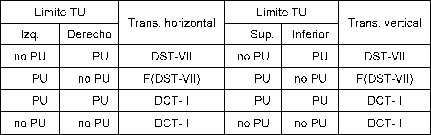
Tabla 2.Table 2.

El F(DST-VII) en la Tabla 1 significa invertir la matriz DST de izquierda a derecha. Los casos de uso de F(DST-VII) también se pueden implementar al cambiar primero los datos de entrada y luego utilizar DST-VII. También es el caso de F(DCT-IV). En la Tabla 1 y la Tabla 2, los elementos “no PU” y “PU” significan límite de no PU y límite de PU, respectivamente. En la Tabla 1 y la Tabla 2, cuando ambos límites de TU en la dirección horizontal o vertical son un límite de PU o un límite que no es de PU, se utiliza DCT-II.The F(DST-VII) in Table 1 means to invert the DST matrix from left to right. F(DST-VII) use cases can also be implemented by first changing the input data and then using DST-VII. It is also the case of F(DCT-IV). In Table 1 and Table 2, the items "non-PU" and "PU" mean non-PU limit and PU limit, respectively. In Table 1 and Table 2, when both TU limits in the horizontal or vertical direction are a PU limit or a non-PU limit, DCT-II is used.
De acuerdo con la Tabla 1, las cuatro TU en la Figura 2 utilizarán transformadas, tal como se muestra en la Tabla 3.According to Table 1, the four TUs in Figure 2 will use transforms, as shown in Table 3.
Tabla 3.Table 3.

El método de la transformada dependiente de los límites (BDT) descrito en JCTVC-G281 puede mejorar el rendimiento general del sistema de codificación. Sin embargo, debido a las características de las TU o PU individuales, es posible que el método BDT, de acuerdo con JCTVC-G281 no siempre logre el mejor rendimiento para un bloque determinado. Es deseable desarrollar un método para mejorar aún más el rendimiento.The Boundary Dependent Transform (BDT) method described in JCTVC-G281 can improve the overall performance of the coding system. However, due to the characteristics of individual TUs or PUs, the BDT method, according to JCTVC-G281, may not always achieve the best performance for a given block. It is desirable to develop a method to further improve performance.
Breve descripción de la invenciónBrief description of the invention
Los objetivos mencionados anteriormente se consiguen mediante un método, un aparato y un flujo de datos, de acuerdo con las reivindicaciones independientes adjuntas, respectivamente.The above-mentioned objects are achieved by a method, an apparatus and a data stream, according to the attached independent claims, respectively.
Se describe un método y un aparato para transformaciones alternativas en un sistema de codificación de video, de acuerdo con un indicador de control. En la presente invención, se determina el indicador de control para la PU actual. Si el indicador de control tiene un primer valor, se aplica una primera transformada a cada TU actual (unidad de la transformada) en el lado del codificador, o se aplica una transformada inversa de la primera transformada a cada TU actual en el lado del decodificador si la TU actual tiene un primer tipo de límite. Además, se aplica una segunda transformada a cada TU actual en el lado del codificador, o se aplica una transformada inversa de la segunda transformada a cada TU actual en el lado del decodificador si la TU actual tiene un segundo tipo de límite. La primera transformada es diferente de la segunda transformada. Por otro lado, si el indicador de control tiene un segundo valor, se aplica una transformada seleccionada a cada TU actual en el lado del codificador, o se aplica una transformada inversa de la transformada seleccionada a cada TU actual en el lado del decodificador, independientemente del tipo de límite de la TU actual.A method and apparatus for alternative transformations in a video coding system, according to a control flag, are described. In the present invention, the control flag for the current PU is determined. If the control flag has a first value, a first transform is applied to each current TU (transform unit) on the encoder side, or an inverse transform of the first transform is applied to each current TU on the decoder side. if the current TU has a first type of limit. In addition, a second transform is applied to each current TU on the encoder side, or an inverse transform of the second transform is applied to each current TU on the decoder side if the current TU has a second limit type. The first transform is different from the second transform. On the other hand, if the control flag has a second value, a selected transform is applied to each current TU on the encoder side, or an inverse transform of the selected transform is applied to each current TU on the decoder side, regardless of the limit type of the current TU.
En la presente invención, el indicador de control puede señalizarse a nivel de TU, PU o CU (unidad de codificación). En la presente invención, el indicador de control puede señalarse explícitamente solo para la PU, TU o CU actual que tiene los primeros tamaños. En la presente invención, el indicador de control puede señalizarse explícitamente dependiendo de otro indicador en un nivel de cabecera de secuencia, imagen o segmento.In the present invention, the control flag may be signaled at the TU, PU or CU (coding unit) level. In the present invention, the control flag can be explicitly signaled only for the current PU, TU or CU having the first sizes. In the present invention, the control pointer may be explicitly signaled depending on another pointer at a sequence, picture or segment header level.
En una realización que no cae dentro del alcance de las reivindicaciones adjuntas, el indicador de control se determina implícitamente en función del tipo de límite de la PU actual, y la primera transformada, la segunda transformada, la transformada seleccionada o una combinación de las mismas, se determina dependiendo en otro indicador que se señaliza explícitamente.In an embodiment not falling within the scope of the appended claims, the control flag is implicitly determined based on the current PU boundary type, and the first transform, the second transform, the selected transform, or a combination thereof. , is determined depending on another flag that is explicitly signaled.
En la presente invención, la segunda transformada corresponde a una versión invertida de la primera transformada. La primera transformada puede corresponder a la transformada de seno discreta tipo V-II (DST-VII), o la transformada de coseno discreta tipo IV (DCT-IV). El primer tipo de límite incluye un límite de PU izquierdo más un límite de no PU derecho y un límite de no PU superior más un límite de PU inferior, y el segundo tipo de límite incluye un límite de no PU izquierdo más un límite de PU derecho y un límite de PU superior límite más un límite inferior no PU. Además, el primer tipo de límite incluye además el límite PU izquierdo más el límite PU derecho, el límite no PU izquierdo más el límite no PU derecho, el límite PU superior más el límite PU inferior, y el límite no PU superior más el límite inferior sin PU.In the present invention, the second transform corresponds to an inverted version of the first transform. The first transform can correspond to the discrete sine transform type V-II (DST-VII), or the discrete cosine transform type IV (DCT-IV). The first type of limit includes a left PU limit plus a right non-PU limit. and an upper non-PU limit plus a lower PU limit, and the second type of limit includes a left non-PU limit plus a right PU limit and an upper PU limit plus a lower non-PU limit. Furthermore, the first type of limit further includes the left PU limit plus the right PU limit, the left non-PU limit plus the right non-PU limit, the upper PU limit plus the lower PU limit, and the upper non-PU limit plus the right PU limit. bottom without PU.
La primera transformada, la segunda transformada, la transformada seleccionada o una combinación de las mismas, puede depender del tamaño de bloque de la PU actual. Por ejemplo, la primera transformada puede corresponder a DST-VII (transformada senoidal discreta tipo V-II) si el tamaño de bloque de la PU actual es 4x4, y la primera transformada puede corresponder a DCT-IV (transformada de coseno discreta tipo IV) si el tamaño de bloque de la PU actual es 8x8 o 16x16. La transformada seleccionada puede corresponder a la transformada de coseno discreta tipo II (DCT-II).The first transform, the second transform, the selected transform, or a combination thereof, may depend on the block size of the current PU. For example, the first transform can correspond to DST-VII (Discrete Sine Transform Type V-II) if the current PU block size is 4x4, and the first transform can correspond to DCT-IV (Discrete Cosine Transform Type IV). ) if the current PU block size is 8x8 or 16x16. The selected transform may correspond to the discrete cosine transform type II (DCT-II).
En otro aspecto que no cae dentro del alcance de las reivindicaciones adjuntas, se describen un método y un aparato para transformaciones alternativas en un sistema de codificación de video de acuerdo con un indicador de control. De acuerdo con una realización que no cae dentro del alcance de las reivindicaciones adjuntas, se determina el indicador de control para la PU actual. Si el indicador de control tiene un primer valor, se aplica una primera transformada a cada TU actual (unidad de la transformada) en un lado del codificador, o se aplica una transformada inversa de la primera transformada a cada TU actual en un lado del decodificador si la TU actual pertenece a un primer tipo. Además, se aplica una segunda transformada a cada TU actual en el lado del codificador o se aplica una transformada inversa de la segunda transformada a cada TU actual en el lado del decodificador si la TU actual pertenece a un segundo tipo. La primera transformada es diferente de la segunda transformada. Por otro lado, si el indicador de control tiene un segundo valor, se aplica una transformada seleccionada a cada TU actual en el lado del codificador, o se aplica una transformada inversa de la transformada seleccionada a cada TU actual en el lado del decodificador independientemente del tipo de límite de la TU actual. En una realización que no cae dentro del alcance de las reivindicaciones adjuntas, si la TU actual pertenece al primer tipo o al segundo tipo, se determina de acuerdo con un tipo de límite, tamaño de bloque, información de modo o una combinación de los mismos.In another aspect not falling within the scope of the appended claims, a method and apparatus for alternate transformations in a video coding system according to a control flag are disclosed. According to an embodiment that does not fall within the scope of the appended claims, the control flag for the current PU is determined. If the control flag has a first value, a first transform is applied to each current TU (transform unit) on one side of the encoder, or an inverse transform of the first transform is applied to each current TU on one decoder side. if the current TU belongs to a first type. Furthermore, a second transform is applied to each current TU on the encoder side or an inverse transform of the second transform is applied to each current TU on the decoder side if the current TU belongs to a second type. The first transform is different from the second transform. On the other hand, if the control flag has a second value, a selected transform is applied to each current TU on the encoder side, or an inverse transform of the selected transform is applied to each current TU on the decoder side regardless of the limit type of the current TU. In an embodiment not falling within the scope of the appended claims, whether the current TU belongs to the first type or the second type is determined according to a boundary type, block size, mode information, or a combination thereof. .
Breve descripción de las figurasBrief description of the figures
La Figura 1 ilustra un ejemplo de los valores de residuos al cuadrado para una PU 4x4.Figure 1 illustrates an example of squared residual values for a 4x4 PU.
La Figura 2 ilustra un ejemplo en el que el error de predicción es mayor cerca de los límites de PU (unidad de predicción) que cerca de los límites interiores de TU (no PU), en donde la PU se divide en cuatro TU (unidades de la transformada). Figure 2 illustrates an example where the prediction error is larger near the limits of PU (prediction unit) than near the inner limits of TU (non-PU), where the PU is divided into four TUs (prediction units). of the transform).
La Figura 3 ilustra un diagrama de flujo a modo de ejemplo, de un sistema de codificación que incorpora una transformada dependiente de las características del bloque basadas en un indicador de control, de acuerdo con una realización de la presente invención.Figure 3 illustrates an exemplary flowchart of a coding system incorporating a transform dependent on block characteristics based on a control flag, in accordance with one embodiment of the present invention.
Descripción detalladaDetailed description
La siguiente descripción es del modo mejor contemplado de llevar a cabo la invención. Esta descripción se realiza con el propósito de ilustrar los principios generales de la invención, y no debe tomarse en un sentido limitativo. El alcance de la invención se determina mejor con referencia a las reivindicaciones adjuntas.The following description is of the best contemplated mode of carrying out the invention. This description is made for the purpose of illustrating the general principles of the invention, and should not be taken in a limiting sense. The scope of the invention is best determined with reference to the appended claims.
Tal como se mencionó anteriormente, se observa que el error de predicción Inter es mayor cerca de los límites de la PU que en el medio de la PU. En consecuencia, en JCTVC-G281 se describe un método de transformada dependiente de los límites (BDT) para adaptar esta distribución desigual de errores en una sola PU. El método BDT selecciona la transformada, de acuerdo con el tipo de límite (es decir, límite no PU o límite de PU), que se resume en la Tabla 1 y la Tabla 2.As mentioned above, the Inter prediction error is observed to be larger near the boundaries of the PU than in the middle of the PU. Consequently, JCTVC-G281 describes a Boundary Dependent Transform (BDT) method to accommodate this uneven error distribution in a single PU. The BDT method selects the transform, according to the type of limit (ie, non-PU limit or PU limit), which is summarized in Table 1 and Table 2.
Sin embargo, para un tipo de límite determinado, el método BDT siempre aplica una transformada de tipo fijo al bloque, como DST-VII o DCT-II. Sin embargo, las características de los residuos de predicción pueden ser bastante diferentes de un bloque a otro. Es posible que el método BDT no siempre logre el mejor rendimiento. En consecuencia, la presente invención describe un método para utilizar un indicador de control para controlar la operación de BDT con el fin de mejorar aún más el rendimiento de BDT. Con el indicador de control explícito, un codificador puede decidir si encender o apagar el BDT utilizando métodos de decisión de modo como la Optimización de Distorsión de Velocidad (RDO). El codificador luego señala el indicador de control para informar al decodificador. Por ejemplo, el indicador de control puede señalizarse en un nivel TU, PU o CU. En un ejemplo, el indicador de control se señaliza solo para la PU, TU o CU actual que tiene un tamaño específico. Sin embargo, el indicador de control también puede determinarse implícitamente. Por ejemplo, el valor del indicador de control puede depender del tamaño del bloque, de modo que la transformada dependiente de los límites esté activada para algunos tamaños de bloque y desactivada para otros tamaños de bloque. Alternativamente, el valor del indicador de control puede depender de la información del modo, de modo que la transformada dependiente del límite se encuentre activada para algunos modos de predicción y desactivada para otros modos de predicción. Además, el indicador de control se puede señalar explícitamente dependiendo de otro indicador en el nivel de encabezado de secuencia, imagen o segmento. Por ejemplo, el otro indicador puede corresponder a present_flag en un nivel de secuencia. Si present_flag es 1, existe el indicador de control. Si present_flag es 0, el indicador de control no existe y su valor se infiere a 0. Cuando el indicador de control se determina implícitamente, se puede señalar otro indicador explícito para seleccionar la transformada para las TU asociadas con la PU.However, for a given boundary type, the BDT method always applies a fixed type transform to the block, such as DST-VII or DCT-II. However, the characteristics of the prediction residuals can be quite different from one block to another. The BDT method may not always achieve the best performance. Accordingly, the present invention describes a method for using a control flag to control the operation of BDT in order to further improve the performance of BDT. With the explicit control flag, an encoder can decide whether to turn the BDT on or off using mode decision methods such as Rate Distortion Optimization (RDO). The encoder then signals the control flag to inform the decoder. For example, the control flag may be signaled at a TU, PU or CU level. In one example, the control flag is signaled only for the current PU, TU or CU having a specific size. However, the control flag can also be set implicitly. For example, the value of the control flag may depend on the block size, such that the bounds-dependent transform is on for some block sizes and off for other block sizes. Alternatively, the value of the control flag may depend on the mode information, such that the bound-dependent transform is on for some prediction modes and off for other prediction modes. In addition, the control flag can be explicitly signaled depending on another flag at the stream, image, or segment header level. For example, the other flag may correspond to present_flag at a sequence level. If present_flag is 1, the control flag exists. If present_flag is 0, the control flag does not exist and its value is inferred to be 0. When the control flag is set implicitly, another explicit flag can be set to select the transform for the TUs associated with the PU.
El indicador de control explícito se puede utilizar de la siguiente manera. Si el indicador de control es igual a 0, se utilizará la DCT original en HEVC para la TU. Si el indicador de control es igual a 1, se utilizará BDT para la TU.The explicit control flag can be used as follows. If the control flag is equal to 0, the original DCT in HEVC will be used for the TU. If the control flag is equal to 1, the BDT shall be used for the TU.
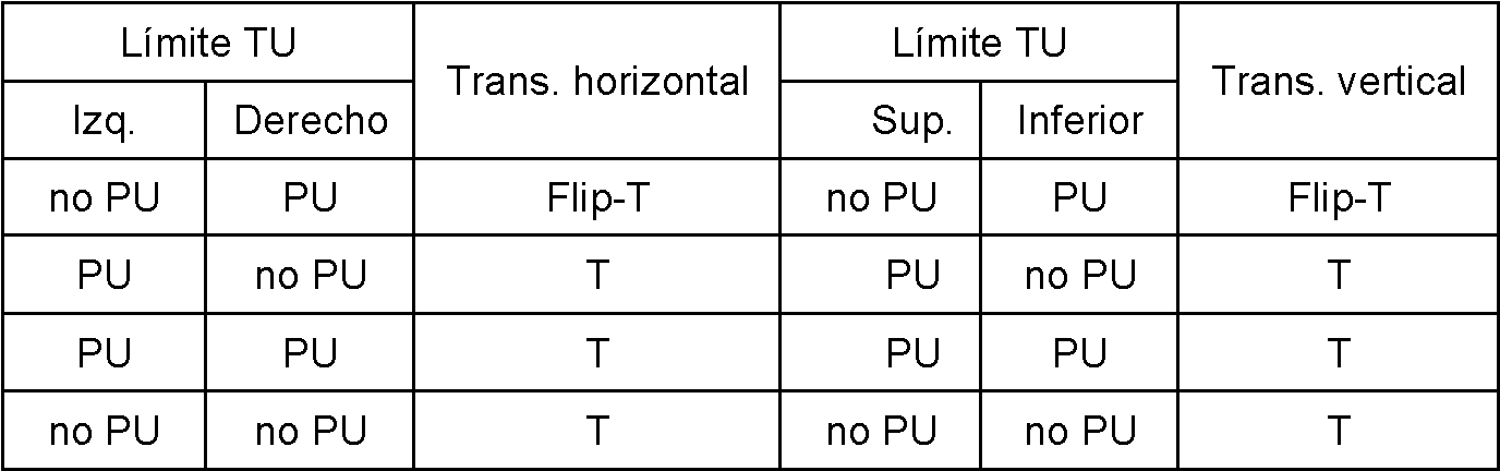
En la presente invención, el indicador de control explícito se puede utilizar como de la siguiente manera. Si el indicador de control es igual a 0, se utilizará la DCT original en HEVC para la TU. Si el indicador de control es igual a 1, se utilizará la BDT para la TU. Sin embargo, la BDT se modifica a partir de la de JCTVC-G281, de modo que la BDT modificada solo sigue la decisión de utilizar la versión invertida o no invertida de la transformada (T). La BDT modificada puede utilizar una transformada diferente de la BDT original para cada tipo de límite. La Tabla 4 ilustra un ejemplo de selección de la transformada para cada tipo de límite. La selección de la transformada puede basarse en el tamaño de bloque de la unidad de la transformada actual (o unidad de predicción actual). Por ejemplo, DST-VII se usa para 4 puntos y DCT-IV para 8 puntos y 16 puntos, respectivamente. En la Tabla 4, Flip-T denota una transformada que utiliza una matriz de la transformada invertida de T. En otro ejemplo, la selección de la transformada puede basarse en la información de modo de la unidad de predicción actual.In the present invention, the explicit control flag can be used as follows. If the control flag is equal to 0, the original DCT in HEVC will be used for the TU. If the control flag is equal to 1, the BDT shall be used for the TU. However, the BDT is modified from that of JCTVC-G281, so the modified BDT only follows the decision to use the inverted or non-inverted version of the transform (T). The modified BDT can use a different transform from the original BDT for each limit type. Table 4 illustrates an example of selecting the transform for each type of boundary. The selection of the transform may be based on the block size of the current transform unit (or current prediction unit). For example, DST-VII is used for 4 points and DCT-IV for 8 points and 16 points, respectively. In Table 4, Flip-T denotes a transform that uses a matrix of the inverted transform of T. In another example, the selection of the transform may be based on the mode information of the current prediction unit.
Tabla 4.Table 4.
En los ejemplos anteriores, se utilizan transformadas específicas tales como DST-VII y DCT-IV como transformadas a modo de ejemplo, para poner en práctica la presente invención. Sin embargo, la presente invención no se limita a las transformadas específicas utilizadas. El indicador de control se puede utilizar para controlar el uso de la transformada dependiente de los límites, independientemente de las transformaciones utilizadas.In the above examples, specific transforms such as DST-VII and DCT-IV are used as exemplary transforms to practice the present invention. However, the present invention is not limited to the specific transforms used. The control flag can be used to control the use of the bounds-dependent transform, regardless of the transformations used.
En una realización que no cae dentro del alcance de las reivindicaciones adjuntas, el indicador de control se puede determinar implícitamente en función del tipo de límite, el tamaño del bloque o la información de movimiento del bloque actual, y la selección de la transformada se determina además dependiendo de que se esté seleccionando otro indicador señalado explícitamente. Por ejemplo, un tipo de transformada actual se determina implícitamente para el bloque actual mediante la selección de un primer tipo de transformada, o un tipo de señalización explícita en función del tipo de límite del bloque, el tamaño del bloque o la información de modo. Si se selecciona el tipo de señalización explícita, el tipo de transformada actual se determina aún más mediante un indicador señalado explícitamente.In an embodiment not falling within the scope of the appended claims, the control flag may be implicitly determined based on the boundary type, block size, or current block motion information, and the selection of the transform is determined. also depending on whether another explicitly indicated indicator is being selected. For example, a current transform type is implicitly determined for the current block by selecting a first transform type, or an explicit signaling type based on the block boundary type, block size, or mode information. If the explicit signaling type is selected, the current transform type is further determined by an explicitly signaled flag.
La Figura 3 ilustra un diagrama de flujo a modo de ejemplo, de un sistema de codificación que incorpora una transformada dependiente de características de bloque basada en un indicador de control, de acuerdo con una realización de la presente invención. El sistema recibe datos de entrada asociados con una PU (unidad de predicción) actual codificada en modo de predicción Inter o Intra, en donde la PU actual se divide en una o más TU (unidades de la transformada) en la etapa 310. Los datos de entrada pueden corresponder a residuos de la PU actual a codificar en el lado del codificador o los residuos codificados de la PU actual en el lado del decodificador. La PU actual puede recuperarse del almacenamiento, como una memoria de computadora o un búfer (RAM o DRAM). El flujo de bits de video también se puede recibir desde un procesador, como una unidad de procesamiento o una señal digital. En la etapa 320 se determina un indicador de control para la PU actual. En la etapa 330 se prueba si el indicador de control tiene un primer valor (por ejemplo, se encuentra activado). Si el resultado es “sí”, se realizan las etapas 340 y 350. Si el resultado es “no”, se realiza la etapa 360. En la etapa 340, se aplica una primera transformada a cada TU actual (unidad de la transformada) en un lado del codificador o una transformada inversa de la primera transformada a cada TU actual en un lado del decodificador si la TU actual pertenece a un primer tipo (es decir, el bloque característico del mismo pertenece al primer tipo). En la etapa 350, se aplica una segunda transformada a cada TU actual en el lado del codificador, o una transformada inversa de la segunda transformada a cada TU actual en el lado del decodificador si la TU actual pertenece a un segundo tipo (es decir, la característica de bloque de la misma pertenece al segundo tipo), donde la primera transformada es diferente de la segunda transformada. En la presente invención, tanto si la TU actual pertenece al primer tipo como si el segundo tipo se encuentra asociado con un tipo límite de la TU actual. En una realización que no cae dentro del alcance de las reivindicaciones adjuntas, si la TU actual pertenece al primer tipo o al segundo tipo se determina de acuerdo con un tipo de límite (por ejemplo, un límite de PU o un límite que no es de PU), bloquear tamaño (por ejemplo, mayor que un tamaño predeterminado o no), información de modo (por ejemplo, información relacionada con un modo de predicción específico), o una combinación de los mismos. En la etapa 360, se aplica una transformada seleccionada a cada TU actual en el lado del codificador o una transformada inversa de la transformada seleccionada a cada TU actual en el lado del decodificador, independientemente del tipo de TU actual. Figure 3 illustrates an exemplary flowchart of a coding system incorporating a block feature dependent transform based on a control flag, in accordance with one embodiment of the present invention. The system receives input data associated with a current PU (prediction unit) encoded in Inter or Intra prediction mode, where the current PU is divided into one or more TUs (transform units) in step 310. The data input may correspond to residues of the current PU to be encoded on the encoder side or the encoded residues of the current PU on the decoder side. The current PU can be retrieved from storage, such as a computer memory or buffer (RAM or DRAM). The video bitstream can also be received from a processor, such as a processing unit or a digital signal. In step 320 a control flag for the current PU is determined. In step 330 it is tested whether the control flag has a first value (for example, it is on). If the result is "yes", steps 340 and 350 are performed. If the result is "no", step 360 is performed. In step 340, a first transform is applied to each current TU (transform unit). on an encoder side or an inverse transform of the first transform to each current TU on a decoder side if the current TU belongs to a first type (ie the characteristic block thereof belongs to the first type). In step 350, a second transform is applied to each current TU on the encoder side, or an inverse transform of the second transform is applied to each current TU on the decoder side if the current TU belongs to a second type (i.e., the block characteristic thereof belongs to the second type), where the first transform is different from the second transform. In the present invention, whether the current TU belongs to the first type or the second type is associated with a boundary type of the current TU. In an embodiment not falling within the scope of the appended claims, whether the current TU belongs to the first type or the second type is determined according to a boundary type (for example, a PU boundary or a non-boundary type). PU), block size (eg, larger than a predetermined size or not), mode information (eg, information related to a specific prediction mode), or a combination thereof. In step 360, a selected transform is applied to each current TU on the encoder side or an inverse transform of the selected transform is applied to each current TU on the decoder side, regardless of the current TU type.
El diagrama de flujo que se muestra anteriormente pretende ilustrar ejemplos de filtrado de predicción Intra, de acuerdo con una realización de la presente invención. Un experto en la materia puede modificar cada etapa, reorganizar las etapas, dividir una etapa o combinar etapas para practicar la presente invención, sin apartarse del espíritu de la presente invención.The flowchart shown above is intended to illustrate examples of Intra prediction filtering, in accordance with one embodiment of the present invention. One skilled in the art may modify each step, rearrange steps, split a step, or combine steps to practice the present invention, without departing from the spirit of the present invention.
La descripción anterior se presenta para permitir que una persona con experiencia ordinaria en la técnica practique la presente invención tal como se proporciona en el contexto de una aplicación particular y su requisito. Varias modificaciones a las realizaciones descritas serán evidentes para los expertos en la técnica, y los principios generales definidos en este documento pueden aplicarse a otras realizaciones. Por lo tanto, no se pretende que la presente invención se limite a las realizaciones particulares mostradas y descritas, sino que debe otorgarse el alcance más amplio, de acuerdo con las reivindicaciones adjuntas. En la descripción detallada anterior, se ilustran varios detalles específicos para proporcionar una comprensión completa de la presente invención. Sin embargo, los expertos en la materia entenderán que la presente invención puede ponerse en práctica.The above description is presented to enable a person of ordinary skill in the art to practice the present invention as provided in the context of a particular application and its requirement. Various modifications to the described embodiments will be apparent to those skilled in the art, and the general principles defined herein may be applied to other embodiments. Therefore, the present invention is not intended to be limited to the particular embodiments shown and described, but rather to be given the broadest scope, in accordance with the appended claims. In the above detailed description, various specific details are illustrated to provide a complete understanding of the present invention. However, those skilled in the art will understand that the present invention can be practiced.
La realización de la presente invención tal como se describió anteriormente, puede implementarse en varios códigos de hardware, software, o una combinación de ambos. Por ejemplo, una realización de la presente invención puede ser uno o más circuitos electrónicos integrados en un chip de compresión de video, o un código de programa integrado en un software de compresión de video para realizar el procesamiento descrito en este documento. Una realización de la presente invención también puede ser un código de programa para ser ejecutado en un Procesador de Señal Digital (DSP), para realizar el procesamiento descrito en este documento. La invención también puede implicar una serie de funciones que debe realizar un procesador de ordenador, un procesador de señales digitales, un microprocesador, o una matriz de puertas programables en campo (FPGA). Estos procesadores pueden configurarse para realizar tareas particulares, de acuerdo con la invención, mediante la ejecución de código de software legible por máquina, o código de firmware que define los métodos particulares incorporados por la invención. El código de software o código de firmware puede desarrollarse en diferentes lenguajes de programación y diferentes formatos o estilos. El código de software también se puede compilar para diferentes plataformas de destino. The embodiment of the present invention as described above may be implemented in various hardware code, software code, or a combination of both. For example, one embodiment of the present invention may be one or more electronic circuitry integrated into a video compression chip, or program code embedded into video compression software to perform the processing described herein. An embodiment of the present invention may also be program code to be executed in a Digital Signal Processor (DSP), to perform the processing described in this document. The invention may also involve a number of functions to be performed by a computer processor, digital signal processor, microprocessor, or field programmable gate array (FPGA). These processors can be configured to perform particular tasks, in accordance with the invention, by executing machine-readable software code, or firmware code that defines the particular methods embodied by the invention. Software code or firmware code can be developed in different programming languages and different formats or styles. The software code can also be compiled for different target platforms.
Claims (3)
Applications Claiming Priority (2)
| Application Number | Priority Date | Filing Date | Title |
|---|---|---|---|
| US201462085358P | 2014-11-28 | 2014-11-28 | |
| PCT/CN2015/095645 WO2016082774A1 (en) | 2014-11-28 | 2015-11-26 | Method and apparatus of alternative transform for video coding |
Publications (1)
| Publication Number | Publication Date |
|---|---|
| ES2930030T3 true ES2930030T3 (en) | 2022-12-05 |
Family
ID=56073628
Family Applications (1)
| Application Number | Title | Priority Date | Filing Date |
|---|---|---|---|
| ES15862450T Active ES2930030T3 (en) | 2014-11-28 | 2015-11-26 | Alternative transform method and apparatus for video coding |
Country Status (7)
| Country | Link |
|---|---|
| US (2) | US10390045B2 (en) |
| EP (2) | EP4090018A1 (en) |
| CN (2) | CN110855988B (en) |
| CA (1) | CA2966862C (en) |
| ES (1) | ES2930030T3 (en) |
| MY (1) | MY190919A (en) |
| WO (1) | WO2016082774A1 (en) |
Families Citing this family (11)
| Publication number | Priority date | Publication date | Assignee | Title |
|---|---|---|---|---|
| US11265578B2 (en) * | 2016-02-04 | 2022-03-01 | Samsung Electronics Co., Ltd. | Video decoding method and apparatus by chroma-multi-transform, and video encoding method and apparatus by chroma-multi-transform |
| KR20170102806A (en) * | 2016-03-02 | 2017-09-12 | 한국전자통신연구원 | Method for encoding/decoding a video signal and apparatus therefor |
| KR20240015154A (en) | 2017-08-04 | 2024-02-02 | 엘지전자 주식회사 | Method and apparatus of configuring transform for video compression |
| WO2019076138A1 (en) * | 2017-10-16 | 2019-04-25 | Huawei Technologies Co., Ltd. | Encoding method and apparatus |
| WO2019102888A1 (en) * | 2017-11-24 | 2019-05-31 | ソニー株式会社 | Image processing device and method |
| US11297348B2 (en) * | 2018-04-13 | 2022-04-05 | Mediatek Inc. | Implicit transform settings for coding a block of pixels |
| AU2018204786A1 (en) * | 2018-06-29 | 2020-01-16 | Canon Kabushiki Kaisha | Method, apparatus and system for encoding and decoding a transformed block of video samples |
| CN113545090A (en) * | 2019-02-01 | 2021-10-22 | 北京达佳互联信息技术有限公司 | Method and apparatus for intra sub-partition coding and decoding mode |
| WO2020167841A1 (en) | 2019-02-11 | 2020-08-20 | Beijing Dajia Internet Information Technology Co., Ltd. | Methods and devices for intra sub-partition coding mode |
| CN109788291A (en) * | 2019-02-12 | 2019-05-21 | 北京大学 | A kind of digital video transform method, device, equipment and storage medium |
| WO2020210489A1 (en) * | 2019-04-10 | 2020-10-15 | Beijing Dajia Internet Information Technology Co., Ltd. | Methods and apparatus of video coding using improved matrix-based intra prediction coding mode |
Family Cites Families (19)
| Publication number | Priority date | Publication date | Assignee | Title |
|---|---|---|---|---|
| KR100612850B1 (en) * | 2004-07-14 | 2006-08-21 | 삼성전자주식회사 | Method and apparatus for predicting coefficient of discrete cosine transform |
| JP2010528555A (en) * | 2007-05-29 | 2010-08-19 | エルジー エレクトロニクス インコーポレイティド | Video signal processing method and apparatus |
| US8631060B2 (en) | 2007-12-13 | 2014-01-14 | Qualcomm Incorporated | Fast algorithms for computation of 5-point DCT-II, DCT-IV, and DST-IV, and architectures |
| US8259808B2 (en) * | 2010-03-25 | 2012-09-04 | Mediatek Inc. | Low complexity video decoder |
| US20120082225A1 (en) * | 2010-10-01 | 2012-04-05 | Qualcomm Incorporated | Selective indication of transform sizes |
| CN104041040B (en) * | 2011-06-30 | 2018-03-06 | 华为技术有限公司 | Prediction residual for lossless video encoding encodes |
| US8929455B2 (en) | 2011-07-01 | 2015-01-06 | Mitsubishi Electric Research Laboratories, Inc. | Method for selecting transform types from mapping table for prediction modes |
| KR101362696B1 (en) | 2011-10-19 | 2014-02-17 | 전북대학교산학협력단 | Signal transformation apparatus applied hybrid architecture, signal transformation method, and recording medium |
| CN103988511B (en) * | 2011-10-31 | 2017-09-08 | 寰发股份有限公司 | The deblocking method and apparatus of video is rebuild in video coding system |
| US10390046B2 (en) | 2011-11-07 | 2019-08-20 | Qualcomm Incorporated | Coding significant coefficient information in transform skip mode |
| CN102857756B (en) | 2012-07-19 | 2015-04-08 | 西安电子科技大学 | Transfer coder adaptive to high efficiency video coding (HEVC) standard |
| US9319684B2 (en) | 2012-08-21 | 2016-04-19 | Qualcomm Incorporated | Alternative transform in scalable video coding |
| WO2014075552A1 (en) * | 2012-11-15 | 2014-05-22 | Mediatek Inc. | Inter-layer texture coding with adaptive transform and multiple inter-layer motion candidates |
| US9380307B2 (en) * | 2012-11-19 | 2016-06-28 | Qualcomm Incorporated | Method and system for intra base layer (BL) transform in video coding |
| US10129550B2 (en) | 2013-02-01 | 2018-11-13 | Qualcomm Incorporated | Inter-layer syntax prediction control |
| US20140376611A1 (en) * | 2013-06-21 | 2014-12-25 | Qualcomm Incorporated | Adaptive color transforms for video coding |
| CN103491372B (en) * | 2013-09-05 | 2018-04-27 | 复旦大学 | A kind of filtering method of deblocking filter suitable for HEVC standard |
| CN103841419B (en) | 2014-01-28 | 2017-01-25 | 福州大学 | HEVC quantized matrix design based on human eye visual characteristics |
| AU2014202921B2 (en) * | 2014-05-29 | 2017-02-02 | Canon Kabushiki Kaisha | Method, apparatus and system for de-blocking a block of video samples |
-
2015
- 2015-11-26 EP EP22183581.2A patent/EP4090018A1/en active Pending
- 2015-11-26 EP EP15862450.2A patent/EP3202146B1/en active Active
- 2015-11-26 CN CN201911271582.6A patent/CN110855988B/en active Active
- 2015-11-26 US US15/525,369 patent/US10390045B2/en active Active
- 2015-11-26 MY MYPI2017701496A patent/MY190919A/en unknown
- 2015-11-26 CA CA2966862A patent/CA2966862C/en active Active
- 2015-11-26 ES ES15862450T patent/ES2930030T3/en active Active
- 2015-11-26 WO PCT/CN2015/095645 patent/WO2016082774A1/en active Application Filing
- 2015-11-26 CN CN201580064516.5A patent/CN107005695B/en active Active
-
2019
- 2019-07-03 US US16/502,535 patent/US11089332B2/en active Active
Also Published As
| Publication number | Publication date |
|---|---|
| WO2016082774A1 (en) | 2016-06-02 |
| US20190327491A1 (en) | 2019-10-24 |
| CN107005695A (en) | 2017-08-01 |
| EP3202146A1 (en) | 2017-08-09 |
| CA2966862C (en) | 2021-03-30 |
| EP3202146A4 (en) | 2018-04-18 |
| MY190919A (en) | 2022-05-19 |
| CN107005695B (en) | 2020-01-07 |
| US10390045B2 (en) | 2019-08-20 |
| US20170366824A1 (en) | 2017-12-21 |
| EP3202146B1 (en) | 2022-08-17 |
| CN110855988A (en) | 2020-02-28 |
| CN110855988B (en) | 2021-09-07 |
| CA2966862A1 (en) | 2016-06-02 |
| EP4090018A1 (en) | 2022-11-16 |
| US11089332B2 (en) | 2021-08-10 |
Similar Documents
| Publication | Publication Date | Title |
|---|---|---|
| ES2930030T3 (en) | Alternative transform method and apparatus for video coding | |
| US11770556B2 (en) | Method and apparatus for processing intra prediction mode | |
| US20200228839A1 (en) | Method and apparatus for a low complexity transform unit partitioning structure for hevc | |
| ES2674163T3 (en) | Coding procedure of an encoding unit at a snapshot limit | |
| JP6415472B2 (en) | Method and apparatus for signaling intra prediction per large block for video encoders and decoders | |
| ES2710782T3 (en) | Video encoding and decoding | |
| ES2612494B1 (en) | METHOD TO INDUCE A FUSION CANDIDATE BLOCK AND DEVICE USING THE SAME | |
| KR101382101B1 (en) | Methods and apparatus for reduced resolution partitioning | |
| ES2743227T3 (en) | Method to encode / decode image | |
| JP5815853B2 (en) | Method and system for transform block processing according to quantization matrix in video coding | |
| KR20170139104A (en) | Partial decoding for arbitrary viewing angles and reduction of line buffers for virtual reality video | |
| ES2883382T3 (en) | Decoding methods and devices | |
| RU2016125260A (en) | Prediction of the block vector in the encoding / decoding of video and images | |
| US20210152828A1 (en) | Flexible Tile Partitions | |
| JP2023072035A (en) | Decoder and program | |
| CN112640455A (en) | Tile partitioning with sub-tiles in video coding | |
| JP7093152B2 (en) | Encoding device, decoding device and program | |
| JP2017204842A (en) | Encoder, decoder and program | |
| JP7092455B2 (en) | Encoding device, decoding device and program | |
| JP2022017254A (en) | Encoder, decoder and program | |
| JP2021090221A (en) | Encoder, decoder and program | |
| JP2023024721A (en) | Coding device, decoding device, and program | |
| JP2020511082A (en) | Image encoding and decoding method, encoding and decoding apparatus, and corresponding computer program |