ES2898224T3 - Dental material with magnetic particles with improved color screening - Google Patents
Dental material with magnetic particles with improved color screening Download PDFInfo
- Publication number
- ES2898224T3 ES2898224T3 ES18193477T ES18193477T ES2898224T3 ES 2898224 T3 ES2898224 T3 ES 2898224T3 ES 18193477 T ES18193477 T ES 18193477T ES 18193477 T ES18193477 T ES 18193477T ES 2898224 T3 ES2898224 T3 ES 2898224T3
- Authority
- ES
- Spain
- Prior art keywords
- coating
- particles
- coating material
- magnetic particles
- magnetic
- Prior art date
- Legal status (The legal status is an assumption and is not a legal conclusion. Google has not performed a legal analysis and makes no representation as to the accuracy of the status listed.)
- Active
Links
Classifications
-
- H—ELECTRICITY
- H01—ELECTRIC ELEMENTS
- H01F—MAGNETS; INDUCTANCES; TRANSFORMERS; SELECTION OF MATERIALS FOR THEIR MAGNETIC PROPERTIES
- H01F1/00—Magnets or magnetic bodies characterised by the magnetic materials therefor; Selection of materials for their magnetic properties
- H01F1/0036—Magnets or magnetic bodies characterised by the magnetic materials therefor; Selection of materials for their magnetic properties showing low dimensional magnetism, i.e. spin rearrangements due to a restriction of dimensions, e.g. showing giant magnetoresistivity
- H01F1/0045—Zero dimensional, e.g. nanoparticles, soft nanoparticles for medical/biological use
- H01F1/0054—Coated nanoparticles, e.g. nanoparticles coated with organic surfactant
-
- A—HUMAN NECESSITIES
- A61—MEDICAL OR VETERINARY SCIENCE; HYGIENE
- A61K—PREPARATIONS FOR MEDICAL, DENTAL OR TOILETRY PURPOSES
- A61K6/00—Preparations for dentistry
- A61K6/15—Compositions characterised by their physical properties
- A61K6/17—Particle size
-
- A—HUMAN NECESSITIES
- A61—MEDICAL OR VETERINARY SCIENCE; HYGIENE
- A61K—PREPARATIONS FOR MEDICAL, DENTAL OR TOILETRY PURPOSES
- A61K6/00—Preparations for dentistry
- A61K6/15—Compositions characterised by their physical properties
- A61K6/16—Refractive index
-
- A—HUMAN NECESSITIES
- A61—MEDICAL OR VETERINARY SCIENCE; HYGIENE
- A61K—PREPARATIONS FOR MEDICAL, DENTAL OR TOILETRY PURPOSES
- A61K6/00—Preparations for dentistry
- A61K6/70—Preparations for dentistry comprising inorganic additives
- A61K6/71—Fillers
-
- A—HUMAN NECESSITIES
- A61—MEDICAL OR VETERINARY SCIENCE; HYGIENE
- A61K—PREPARATIONS FOR MEDICAL, DENTAL OR TOILETRY PURPOSES
- A61K6/00—Preparations for dentistry
- A61K6/80—Preparations for artificial teeth, for filling teeth or for capping teeth
- A61K6/831—Preparations for artificial teeth, for filling teeth or for capping teeth comprising non-metallic elements or compounds thereof, e.g. carbon
-
- A—HUMAN NECESSITIES
- A61—MEDICAL OR VETERINARY SCIENCE; HYGIENE
- A61K—PREPARATIONS FOR MEDICAL, DENTAL OR TOILETRY PURPOSES
- A61K6/00—Preparations for dentistry
- A61K6/80—Preparations for artificial teeth, for filling teeth or for capping teeth
- A61K6/84—Preparations for artificial teeth, for filling teeth or for capping teeth comprising metals or alloys
-
- A—HUMAN NECESSITIES
- A61—MEDICAL OR VETERINARY SCIENCE; HYGIENE
- A61K—PREPARATIONS FOR MEDICAL, DENTAL OR TOILETRY PURPOSES
- A61K6/00—Preparations for dentistry
- A61K6/80—Preparations for artificial teeth, for filling teeth or for capping teeth
- A61K6/849—Preparations for artificial teeth, for filling teeth or for capping teeth comprising inorganic cements
- A61K6/871—Quartz; SiO2
-
- A—HUMAN NECESSITIES
- A61—MEDICAL OR VETERINARY SCIENCE; HYGIENE
- A61K—PREPARATIONS FOR MEDICAL, DENTAL OR TOILETRY PURPOSES
- A61K6/00—Preparations for dentistry
- A61K6/80—Preparations for artificial teeth, for filling teeth or for capping teeth
- A61K6/849—Preparations for artificial teeth, for filling teeth or for capping teeth comprising inorganic cements
- A61K6/88—Chromium oxide
-
- A—HUMAN NECESSITIES
- A61—MEDICAL OR VETERINARY SCIENCE; HYGIENE
- A61K—PREPARATIONS FOR MEDICAL, DENTAL OR TOILETRY PURPOSES
- A61K6/00—Preparations for dentistry
- A61K6/80—Preparations for artificial teeth, for filling teeth or for capping teeth
- A61K6/884—Preparations for artificial teeth, for filling teeth or for capping teeth comprising natural or synthetic resins
-
- C—CHEMISTRY; METALLURGY
- C09—DYES; PAINTS; POLISHES; NATURAL RESINS; ADHESIVES; COMPOSITIONS NOT OTHERWISE PROVIDED FOR; APPLICATIONS OF MATERIALS NOT OTHERWISE PROVIDED FOR
- C09C—TREATMENT OF INORGANIC MATERIALS, OTHER THAN FIBROUS FILLERS, TO ENHANCE THEIR PIGMENTING OR FILLING PROPERTIES ; PREPARATION OF CARBON BLACK ; PREPARATION OF INORGANIC MATERIALS WHICH ARE NO SINGLE CHEMICAL COMPOUNDS AND WHICH ARE MAINLY USED AS PIGMENTS OR FILLERS
- C09C1/00—Treatment of specific inorganic materials other than fibrous fillers; Preparation of carbon black
- C09C1/0015—Pigments exhibiting interference colours, e.g. transparent platelets of appropriate thinness or flaky substrates, e.g. mica, bearing appropriate thin transparent coatings
- C09C1/0051—Pigments exhibiting interference colours, e.g. transparent platelets of appropriate thinness or flaky substrates, e.g. mica, bearing appropriate thin transparent coatings comprising a stack of coating layers with alternating low and high refractive indices, wherein the first coating layer on the core surface has the low refractive index
-
- C—CHEMISTRY; METALLURGY
- C01—INORGANIC CHEMISTRY
- C01P—INDEXING SCHEME RELATING TO STRUCTURAL AND PHYSICAL ASPECTS OF SOLID INORGANIC COMPOUNDS
- C01P2004/00—Particle morphology
- C01P2004/60—Particles characterised by their size
- C01P2004/62—Submicrometer sized, i.e. from 0.1-1 micrometer
-
- C—CHEMISTRY; METALLURGY
- C01—INORGANIC CHEMISTRY
- C01P—INDEXING SCHEME RELATING TO STRUCTURAL AND PHYSICAL ASPECTS OF SOLID INORGANIC COMPOUNDS
- C01P2004/00—Particle morphology
- C01P2004/60—Particles characterised by their size
- C01P2004/64—Nanometer sized, i.e. from 1-100 nanometer
-
- C—CHEMISTRY; METALLURGY
- C01—INORGANIC CHEMISTRY
- C01P—INDEXING SCHEME RELATING TO STRUCTURAL AND PHYSICAL ASPECTS OF SOLID INORGANIC COMPOUNDS
- C01P2004/00—Particle morphology
- C01P2004/80—Particles consisting of a mixture of two or more inorganic phases
-
- C—CHEMISTRY; METALLURGY
- C01—INORGANIC CHEMISTRY
- C01P—INDEXING SCHEME RELATING TO STRUCTURAL AND PHYSICAL ASPECTS OF SOLID INORGANIC COMPOUNDS
- C01P2004/00—Particle morphology
- C01P2004/80—Particles consisting of a mixture of two or more inorganic phases
- C01P2004/82—Particles consisting of a mixture of two or more inorganic phases two phases having the same anion, e.g. both oxidic phases
- C01P2004/84—Particles consisting of a mixture of two or more inorganic phases two phases having the same anion, e.g. both oxidic phases one phase coated with the other
-
- C—CHEMISTRY; METALLURGY
- C01—INORGANIC CHEMISTRY
- C01P—INDEXING SCHEME RELATING TO STRUCTURAL AND PHYSICAL ASPECTS OF SOLID INORGANIC COMPOUNDS
- C01P2006/00—Physical properties of inorganic compounds
- C01P2006/42—Magnetic properties
-
- C—CHEMISTRY; METALLURGY
- C01—INORGANIC CHEMISTRY
- C01P—INDEXING SCHEME RELATING TO STRUCTURAL AND PHYSICAL ASPECTS OF SOLID INORGANIC COMPOUNDS
- C01P2006/00—Physical properties of inorganic compounds
- C01P2006/60—Optical properties, e.g. expressed in CIELAB-values
-
- C—CHEMISTRY; METALLURGY
- C09—DYES; PAINTS; POLISHES; NATURAL RESINS; ADHESIVES; COMPOSITIONS NOT OTHERWISE PROVIDED FOR; APPLICATIONS OF MATERIALS NOT OTHERWISE PROVIDED FOR
- C09C—TREATMENT OF INORGANIC MATERIALS, OTHER THAN FIBROUS FILLERS, TO ENHANCE THEIR PIGMENTING OR FILLING PROPERTIES ; PREPARATION OF CARBON BLACK ; PREPARATION OF INORGANIC MATERIALS WHICH ARE NO SINGLE CHEMICAL COMPOUNDS AND WHICH ARE MAINLY USED AS PIGMENTS OR FILLERS
- C09C2200/00—Compositional and structural details of pigments exhibiting interference colours
- C09C2200/10—Interference pigments characterized by the core material
- C09C2200/1004—Interference pigments characterized by the core material the core comprising at least one inorganic oxide, e.g. Al2O3, TiO2 or SiO2
-
- C—CHEMISTRY; METALLURGY
- C09—DYES; PAINTS; POLISHES; NATURAL RESINS; ADHESIVES; COMPOSITIONS NOT OTHERWISE PROVIDED FOR; APPLICATIONS OF MATERIALS NOT OTHERWISE PROVIDED FOR
- C09C—TREATMENT OF INORGANIC MATERIALS, OTHER THAN FIBROUS FILLERS, TO ENHANCE THEIR PIGMENTING OR FILLING PROPERTIES ; PREPARATION OF CARBON BLACK ; PREPARATION OF INORGANIC MATERIALS WHICH ARE NO SINGLE CHEMICAL COMPOUNDS AND WHICH ARE MAINLY USED AS PIGMENTS OR FILLERS
- C09C2200/00—Compositional and structural details of pigments exhibiting interference colours
- C09C2200/10—Interference pigments characterized by the core material
- C09C2200/1054—Interference pigments characterized by the core material the core consisting of a metal
-
- C—CHEMISTRY; METALLURGY
- C09—DYES; PAINTS; POLISHES; NATURAL RESINS; ADHESIVES; COMPOSITIONS NOT OTHERWISE PROVIDED FOR; APPLICATIONS OF MATERIALS NOT OTHERWISE PROVIDED FOR
- C09C—TREATMENT OF INORGANIC MATERIALS, OTHER THAN FIBROUS FILLERS, TO ENHANCE THEIR PIGMENTING OR FILLING PROPERTIES ; PREPARATION OF CARBON BLACK ; PREPARATION OF INORGANIC MATERIALS WHICH ARE NO SINGLE CHEMICAL COMPOUNDS AND WHICH ARE MAINLY USED AS PIGMENTS OR FILLERS
- C09C2200/00—Compositional and structural details of pigments exhibiting interference colours
- C09C2200/30—Interference pigments characterised by the thickness of the core or layers thereon or by the total thickness of the final pigment particle
- C09C2200/302—Thickness of a layer with high refractive material
-
- C—CHEMISTRY; METALLURGY
- C09—DYES; PAINTS; POLISHES; NATURAL RESINS; ADHESIVES; COMPOSITIONS NOT OTHERWISE PROVIDED FOR; APPLICATIONS OF MATERIALS NOT OTHERWISE PROVIDED FOR
- C09C—TREATMENT OF INORGANIC MATERIALS, OTHER THAN FIBROUS FILLERS, TO ENHANCE THEIR PIGMENTING OR FILLING PROPERTIES ; PREPARATION OF CARBON BLACK ; PREPARATION OF INORGANIC MATERIALS WHICH ARE NO SINGLE CHEMICAL COMPOUNDS AND WHICH ARE MAINLY USED AS PIGMENTS OR FILLERS
- C09C2200/00—Compositional and structural details of pigments exhibiting interference colours
- C09C2200/30—Interference pigments characterised by the thickness of the core or layers thereon or by the total thickness of the final pigment particle
- C09C2200/303—Thickness of a layer with low refractive material
-
- C—CHEMISTRY; METALLURGY
- C09—DYES; PAINTS; POLISHES; NATURAL RESINS; ADHESIVES; COMPOSITIONS NOT OTHERWISE PROVIDED FOR; APPLICATIONS OF MATERIALS NOT OTHERWISE PROVIDED FOR
- C09C—TREATMENT OF INORGANIC MATERIALS, OTHER THAN FIBROUS FILLERS, TO ENHANCE THEIR PIGMENTING OR FILLING PROPERTIES ; PREPARATION OF CARBON BLACK ; PREPARATION OF INORGANIC MATERIALS WHICH ARE NO SINGLE CHEMICAL COMPOUNDS AND WHICH ARE MAINLY USED AS PIGMENTS OR FILLERS
- C09C2200/00—Compositional and structural details of pigments exhibiting interference colours
- C09C2200/30—Interference pigments characterised by the thickness of the core or layers thereon or by the total thickness of the final pigment particle
- C09C2200/308—Total thickness of the pigment particle
-
- C—CHEMISTRY; METALLURGY
- C09—DYES; PAINTS; POLISHES; NATURAL RESINS; ADHESIVES; COMPOSITIONS NOT OTHERWISE PROVIDED FOR; APPLICATIONS OF MATERIALS NOT OTHERWISE PROVIDED FOR
- C09C—TREATMENT OF INORGANIC MATERIALS, OTHER THAN FIBROUS FILLERS, TO ENHANCE THEIR PIGMENTING OR FILLING PROPERTIES ; PREPARATION OF CARBON BLACK ; PREPARATION OF INORGANIC MATERIALS WHICH ARE NO SINGLE CHEMICAL COMPOUNDS AND WHICH ARE MAINLY USED AS PIGMENTS OR FILLERS
- C09C2210/00—Special effects or uses of interference pigments
Abstract
Material dental polimerizable que contiene por lo menos un compuesto polimerizable por radicales y partículas magnéticas que comprenden un núcleo magnético y un primer recubrimiento de un primer material de revestimiento, caracterizado por que se aplica a la superficie del primer recubrimiento orientada en dirección opuesta al núcleo un segundo recubrimiento de un segundo material de revestimiento, siendo el segundo material de revestimiento diferente del primer material de revestimiento y presentando un índice de refracción superior al del primer material de revestimiento.Polymerizable dental material containing at least one compound polymerizable by radicals and magnetic particles comprising a magnetic core and a first coating of a first coating material, characterized in that it is applied to the surface of the first coating oriented in the opposite direction to the core a second coating of a second coating material, the second coating material being different from the first coating material and having a higher refractive index than the first coating material.
Description
DESCRIPCIÓNDESCRIPTION
Material dental con partículas magnéticas con apantallamiento de color mejoradoDental material with magnetic particles with improved color screening
La presente invención se refiere a materiales dentales, en particular para la producción de adhesivos y cementos. The present invention relates to dental materials, in particular for the production of adhesives and cements.
Las partículas magnéticas y, en particular, las nanopartículas magnéticas, es decir, las partículas magnéticas con un diámetro inferior a 300 nm, son de gran interés por su gran potencial de aplicación en diversos sectores tales como, entre otros, catálisis, diagnóstico, tratamiento médico, tratamiento de agua y almacenamiento de datos. Magnetic particles and, in particular, magnetic nanoparticles, that is, magnetic particles with a diameter of less than 300 nm, are of great interest due to their great potential for application in various sectors such as, among others, catalysis, diagnosis, treatment medical, water treatment and data storage.
Para proteger o estabilizar las partículas, por ejemplo contra la corrosión o la aglomeración, es conocida la aplicación de un recubrimiento a las partículas. Un recubrimiento también puede servir para funcionalizar adicionalmente o modificar las partículas para otras aplicaciones diferentes. Por ejemplo, el documento DE 10 2015 118816 describe nanopartículas de óxido de hierro anisotrópicas con un diámetro comprendido entre 3 y 50 nm, que están embebidas en una matriz de silicato y pueden utilizarse como un componente de características de seguridad, por ejemplo en documentos o valores. En el documento DE 41 17 782, por ejemplo, se divulgan partículas de óxido de hierro magnéticas nanocristalinas, que están rodeadas por un material de revestimiento constituido por glicosaminoglicanos naturales o sintéticos, y su uso en diagnósticos y tratamientos médicos. Además el documento EP 1 894 214 divulga un procedimiento para la producción de partículas magnéticas recubiertas de sílice y su uso para la purificación de ácidos nucleicos a partir de muestras biológicas corporales. To protect or stabilize the particles, for example against corrosion or agglomeration, it is known to apply a coating to the particles. A coating may also serve to further functionalize or modify the particles for various other applications. For example, DE 10 2015 118816 describes anisotropic iron oxide nanoparticles with a diameter between 3 and 50 nm, which are embedded in a silicate matrix and can be used as a component of security features, for example in documents or values. In DE 41 17 782, for example, nanocrystalline magnetic iron oxide particles are disclosed, which are surrounded by a coating material consisting of natural or synthetic glycosaminoglycans, and their use in medical diagnostics and treatment. Furthermore EP 1 894 214 discloses a process for the production of silica-coated magnetic particles and their use for the purification of nucleic acids from biological body samples.
También se sabe que se pueden utilizar partículas magnéticas, en principio, para la generación indirecta local de calor. Así, las partículas magnéticas que están expuestas a un campo alterno electromagnético pueden convertir parte de la energía del campo alterno en calor debido a procesos de histéresis y relajación. Un ejemplo de aplicación que utiliza este efecto es el tratamiento térmico de células tumorales con calentamiento inductivo controlado a distancia en el intervalo de radiofrecuencia, siendo destruidas las células tumorales por la acción local del calor.It is also known that magnetic particles can be used, in principle, for the local indirect generation of heat. Thus, magnetic particles that are exposed to an electromagnetic alternating field can convert part of the energy of the alternating field into heat due to hysteresis and relaxation processes. An example of an application that uses this effect is the thermal treatment of tumor cells with remotely controlled inductive heating in the radiofrequency range, the tumor cells being destroyed by the local action of heat.
La capacidad de generar calor de forma inductiva de las partículas magnéticas también se puede utilizar para el desprendimiento selectivo de uniones adhesivas, lo que se denomina despegado bajo demanda (DoD). A este respecto, el desprendimiento (despegado) de las uniones adhesivas se puede lograr selectivamente (bajo demanda) reduciendo significativamente la resistencia mecánica de la capa de unión adhesiva mediante calentamiento. Por ejemplo, el documento WO 2013/034777 propone la incorporación de nanopartículas ferromagnéticas en materiales dentales, en particular adhesivos y cementos, con el fin de conseguir un calentamiento inductivo del material dental mediante la acción de un campo magnético alterno. En el sector dental, el desprendimiento de uniones adhesivas es importante, entre otros, en ortodoncia, en la que los apliques ortodóncicos que se adhieren a la superficie del diente para corregir los dientes mal posicionados deben retirarse después de la corrección sin dañar el esmalte dental. Además, en el caso de la reparación o la sustitución completa de restauraciones o coronas cerámicas de alta resistencia mecánica, que solo pueden retirarse mecánicamente con un gran esfuerzo, serían ventajosos los materiales compuestos de cemento fácilmente reblandecibles o separables.The inductive heat generating ability of magnetic particles can also be used for the selective detachment of adhesive bonds, which is called peel-on-demand (DoD). In this regard, the detachment (peeling) of the adhesive bonds can be achieved selectively (on demand) by significantly reducing the mechanical strength of the adhesive bonding layer by heating. For example, document WO 2013/034777 proposes the incorporation of ferromagnetic nanoparticles in dental materials, in particular adhesives and cements, in order to achieve inductive heating of dental material through the action of an alternating magnetic field. In the dental sector, the detachment of adhesive bonds is important, among others in orthodontics, in which orthodontic appliances that adhere to the tooth surface to correct misaligned teeth must be removed after correction without damaging the tooth enamel . Furthermore, in the case of repair or complete replacement of high-strength ceramic restorations or crowns, which can only be mechanically removed with great effort, easily softenable or removable cement composite materials would be advantageous.
Una desventaja de la utilización de partículas magnéticas en los materiales dentales, sin embargo, es a menudo el color oscuro de las partículas magnéticas. En particular, las partículas cuyo diámetro es lo suficientemente grande como para proporcionar propiedades magnéticas adaptadas para aplicaciones de despegado bajo demanda, tales como, por ejemplo, una coercitividad suficiente, son visibles para el ojo humano como un punto gris u oscuro en el material dental o dan lugar, en general, a un oscurecimiento del material dental, lo que es indeseable por motivos estéticos.A disadvantage of the use of magnetic particles in dental materials, however, is often the dark color of the magnetic particles. In particular, particles whose diameter is large enough to provide magnetic properties tailored for peel-on-demand applications, such as, for example, sufficient coercivity, are visible to the human eye as a gray or dark dot in the dental material. or they generally lead to a darkening of the dental material, which is undesirable for aesthetic reasons.
Se sabe que el color de las partículas magnéticas se aclara mediante la adición de pigmentos blancos. Por ejemplo, el documento JP 2000/150218 describe el recubrimiento de núcleos magnéticos con pigmentos blancos. El documento JP 2003/002658 divulga partículas magnéticas blancas obtenidas disponiendo partículas magnéticas finas de óxido de hierro en la superficie de núcleos de TiO2 blancos. Además, el documento US 5.194.356 y el documento WO 2010/149150 describen, en cada caso, la incorporación de partículas magnéticas y pigmentos blancos en una matriz polimérica.The color of magnetic particles is known to be lightened by the addition of white pigments. For example, JP 2000/150218 describes the coating of magnetic cores with white pigments. JP 2003/002658 discloses white magnetic particles obtained by arranging fine iron oxide magnetic particles on the surface of white TiO 2 cores. Furthermore, US 5,194,356 and WO 2010/149150 each describe the incorporation of magnetic particles and white pigments in a polymeric matrix.
Los documentos DE 112012005417, JP 3032927, EP 0959107 y EP 0609897 describen partículas magnéticas con varios revestimientos y un índice de refracción creciente.DE 112012005417, JP 3032927, EP 0959107 and EP 0609897 describe magnetic particles with various coatings and an increasing refractive index.
No obstante, los presentes inventores han descubierto que las partículas magnéticas que se aclaran con pigmentos, tales como, por ejemplo, las partículas de óxido de hierro con un recubrimiento que contiene sílice, y en el aire presentan un color casi neutro con solo un tono ligeramente gris claro, cuando se embeben en un medio dental, tal como, por ejemplo, un cemento dental, muestran un color significativamente más oscuro.However, the present inventors have found that magnetic particles that are lightened with pigments, such as, for example, iron oxide particles with a silica-containing coating, and in air exhibit a nearly neutral color with only a slight hue. slightly light gray, when embedded in a dental medium, such as, for example, dental cement, they show a significantly darker color.
Por lo tanto, la invención se basa en el objeto de proporcionar partículas con un apantallamiento de color mejorado. En particular, la invención se basa en el objeto de proporcionar partículas magnéticas que presenten suficientes propiedades magnéticas para la generación local inducida de calor y, por lo tanto, sean adecuadas para aplicaciones de despegado bajo demanda en el sector dental, y al mismo tiempo presenten en medios adhesivos, tales como adhesivos dentales o cementos dentales, una apariencia estética, es decir, un color lo más neutro posible.Therefore, the invention is based on the object of providing particles with improved color blinding. In particular, the invention is based on the object of providing magnetic particles that have sufficient magnetic properties for local induced heat generation and therefore are suitable for peel-on-demand applications in the dental sector, and at the same time present in adhesive media, such as dental adhesives or dental cements, an aesthetic appearance, it is that is, a color as neutral as possible.
Según la invención, este objeto se logra mediante el material dental polimerizable de la reivindicación 1 con partículas magnéticas que comprenden un núcleo magnético y un primer recubrimiento de un primer material de revestimiento, aplicándose a la superficie del primer recubrimiento orientada en dirección opuesta al núcleo un segundo recubrimiento de un segundo material de revestimiento, siendo el segundo material de revestimiento diferente del primer material de revestimiento y presentando un índice de refracción superior al del primer material de revestimiento.According to the invention, this object is achieved by the polymerizable dental material of claim 1 with magnetic particles comprising a magnetic core and a first coating of a first coating material, applying to the surface of the first coating oriented in the opposite direction to the core a second coating of a second coating material, the second coating material being different from the first coating material and having a higher refractive index than the first coating material.
Sorprendentemente se ha descubierto que la combinación según la invención de un primer y segundo recubrimiento puede apantallar eficazmente un color no deseado del núcleo de las partículas, en particular el color oscuro no deseado de las partículas magnéticas, no solo en el aire sino también en medios adhesivos tales como adhesivos dentales o cementos dentales. Así, las partículas magnéticas según la invención no solo se caracterizan por poseer suficientes propiedades magnéticas para la generación de calor local inducida, sino en particular también por excelentes propiedades ópticas cuando están embebidas en medios adhesivos. Sin pretender vincularse a ninguna teoría, se supone que, en el caso de las partículas según la invención, se minimiza un color oscuro no deseado, es decir, la absorción de la luz incidente por el material del núcleo, ya que la luz incidente se desvía del núcleo gracias a la relación según la invención de los índices de refracción de los materiales de revestimiento, y el doble revestimiento, por lo tanto, produce una focalización de la luz incidente en el exterior del núcleo. El recubrimiento según la invención de núcleos magnéticos puede producir, por lo tanto, un apantallamiento de color eficaz, incluso cuando las partículas están embebidas en medios con un índice de refracción superior a 1,0, tal como, por ejemplo, entre 1,4 y 1,5, como ocurre habitualmente con medios adhesivos en el sector dental. Surprisingly it has been found that the combination according to the invention of a first and second coating can effectively screen out an undesirable color of the core of the particles, in particular the undesirable dark color of the magnetic particles, not only in air but also in media. adhesives such as dental adhesives or dental cements. Thus, the magnetic particles according to the invention are characterized not only by having sufficient magnetic properties for induced local heat generation, but in particular also by excellent optical properties when embedded in adhesive media. Without wishing to be bound by theory, it is assumed that, in the case of the particles according to the invention, an undesirable dark colour, i.e. the absorption of incident light by the core material, is minimized, since the incident light is it deviates from the core thanks to the relationship according to the invention of the refractive indices of the cladding materials, and the double cladding therefore produces a focusing of the incident light on the outside of the core. The coating according to the invention of magnetic cores can therefore produce effective color screening, even when the particles are embedded in media with a refractive index greater than 1.0, such as, for example, between 1.4 and 1.5, as is usually the case with adhesive media in the dental sector.
Para conseguir el apantallamiento de color deseado de la forma más eficaz posible, en una forma de realización tanto el primer como el segundo recubrimiento están diseñados como un recubrimiento continuo. La superficie del núcleo está cubierta de forma particularmente preferida por completo por el primer material de revestimiento y la superficie del primer recubrimiento orientada en dirección opuesta al núcleo está completamente cubierta por el segundo material de revestimiento. Además, se prefiere que tanto el primer como el segundo recubrimiento se formen de una manera esencialmente uniforme, es decir, que tanto el espesor del primer recubrimiento como el del segundo recubrimiento sean esencialmente constantes en toda su extensión.To achieve the desired color screening as effectively as possible, in one embodiment both the first and second coatings are designed as one continuous coating. The core surface is particularly preferably completely covered by the first coating material and the surface of the first coating facing away from the core is completely covered by the second coating material. Furthermore, it is preferred that both the first and second coatings are formed in an essentially uniform manner, ie, that both the thickness of the first and second coatings are essentially constant throughout their length.
En una forma de realización preferida, en la que el apantallamiento de color deseado del núcleo es particularmente eficaz, la relación entre el índice de refracción del segundo material de revestimiento y el índice de refracción del primer material de revestimiento está comprendido entre 1,1 y 2,6, preferentemente entre 1,4 y 2,0, de forma particularmente preferida entre 1,6 y 1,8.In a preferred embodiment, in which the desired color screening of the core is particularly effective, the ratio between the refractive index of the second cladding material and the refractive index of the first cladding material is between 1.1 and 2.6, preferably between 1.4 and 2.0, particularly preferably between 1.6 and 1.8.
En una forma de realización, el primer material de revestimiento presenta un índice de refracción comprendido entre 1,1 y 2,5, preferentemente entre 1,2 y 1,9, de forma particularmente preferida entre 1,3 y 1,7. Además, el segundo material de revestimiento presenta preferentemente un índice de refracción comprendido entre 1,7 y 3,1, en particular entre 2,1 y 3,1, de forma particularmente preferida entre 2,5 y 3,1.In one embodiment, the first coating material has a refractive index of between 1.1 and 2.5, preferably between 1.2 and 1.9, particularly preferably between 1.3 and 1.7. Furthermore, the second coating material preferably has a refractive index of between 1.7 and 3.1, in particular between 2.1 and 3.1, particularly preferably between 2.5 and 3.1.
A menos que se indique lo contrario, el índice de refracción del primer y el segundo material de revestimiento en la presente solicitud se refiere a la constante del material respectivo a una longitud de onda de 589 nm (línea D de sodio) y una temperatura de 25°C.Unless otherwise indicated, the refractive index of the first and second coating materials in the present application refers to the constant of the respective material at a wavelength of 589 nm (sodium D line) and a temperature of 25°C
En otra forma de realización, se prefiere que la relación entre el espesor del segundo revestimiento y el espesor del primer revestimiento sea de entre 0,1 y 2,5, preferentemente entre 0,5 y 2,0, de forma particularmente preferida entre 1,0 y 2,0. En particular, el espesor del primer recubrimiento es preferentemente a entre 50 y 1000 nm, de forma particularmente preferida entre 100 y 600 nm. Además, el espesor del segundo recubrimiento es preferentemente de entre 50 y 1000 nm, de forma particularmente preferida entre 100 y 600 nm.In another embodiment, it is preferred that the ratio between the thickness of the second coating and the thickness of the first coating is between 0.1 and 2.5, preferably between 0.5 and 2.0, particularly preferably between 1 .0 and 2.0. In particular, the thickness of the first coating is preferably between 50 and 1000 nm, particularly preferably between 100 and 600 nm. Furthermore, the thickness of the second coating is preferably between 50 and 1000 nm, particularly preferably between 100 and 600 nm.
A este respecto, el espesor del primer y del segundo recubrimiento se determina mediante microscopía electrónica de barrido (SEM), restando el diámetro promedio en número de las partículas con el recubrimiento que se va a determinar del diámetro promedio en número de las partículas sin el recubrimiento que se va a determinar. El espesor del recubrimiento es igual a la mitad de esta diferencia de diámetro, es decir, el espesor del recubrimiento corresponde a la diferencia entre los radios correspondientes.In this regard, the thickness of the first and second coatings is determined by scanning electron microscopy (SEM) by subtracting the number average diameter of the particles with the coating to be determined from the number average diameter of the particles without the coating. coating to be determined. The thickness of the coating is equal to half of this difference in diameter, that is, the thickness of the coating corresponds to the difference between the corresponding radii.
También se prefiere que la relación entre el espesor del segundo recubrimiento y el radio del primer recubrimiento sea de 0,1 a 1, preferentemente de 0,2 a 0,8, de forma particularmente preferida de 0,28 a 0,8.It is also preferred that the ratio of the thickness of the second coating to the radius of the first coating is 0.1 to 1, preferably 0.2 to 0.8, particularly preferably 0.28 to 0.8.
El radio del primer recubrimiento se determina, en particular, mediante microscopía electrónica de barrido (SEM), presentando preferentemente el núcleo recubierto con el primer recubrimiento una forma esencialmente esférica y el radio del primer recubrimiento, por lo tanto, es la mitad del diámetro promedio en número de los núcleos provistos del primer recubrimiento. The radius of the first coating is determined, in particular, by scanning electron microscopy (SEM), the core coated with the first coating preferably having an essentially spherical shape and the radius of the first coating is therefore half the average diameter in number of cores provided with the first coating.
A este respecto, el segundo material de revestimiento se selecciona de forma particularmente preferida de entre el grupo que consiste en TO2, ZrO2, ZnS, AhO3, poli(metacrilato de pentabromofenilo) y mezclas de los mismos. Además, el primer material de revestimiento se selecciona de forma particularmente preferida de entre el grupo que consiste en SO2, acrilato de SO2, poliestireno, poli(metacrilato de metilo), poli(alcohol vinílico), poli(acrilato de alquilo), policarbonato, MgF2, polímero fluorado, AhO3, ZnO2 y mezclas de los mismos. A este respecto, el término "acrilato de SO2" significa polímeros de metacrilato de 3-(trimetoxisilil)propilo (TPM). Los ejemplos de polímeros fluorados adecuados comprenden acrilatos fluorados con bajo índice de refracción, por ejemplo poli(acrilato de 1,1,1,3,3,3-hexafluoroisopropilo), poli(acrilato de 2,2,3,3,4,4,4-heptafluorobutilo), poli(metacrilato de 2,2,3,3,4,4,4-heptafluorobutilo), poli(acrilato de 2,2,3,3,3-pentafluoropropilo), poli(metacrilato de 1,1,1,3,3,3-hexafluoroisopropilo), poli(acrilato de 2,2,3,4,4,4-hexafluorobutilo), poli(metacrilato de 2,2,3,4,4,4-hexafluorobutilo), poli(metacrilato de 2,2,3,3,3-pentafluoropropilo), poli(acrilato de 2,2,2-trifluoroetilo), poli(acrilato de 2,2,3,3-tetrafluoropropilo), poli(metacrilato de 2,2,3,3-tetrafluoropropilo) y poli(metacrilato de 2,2,2-trifluoroetilo). In this regard, the second coating material is particularly preferably selected from the group consisting of TO2, ZrO2, ZnS, AhO3, polypentabromophenyl methacrylate, and mixtures thereof. Furthermore, the first coating material is particularly preferably selected from the group consisting of SO2, SO2 acrylate, polystyrene, poly(methyl methacrylate), poly(vinyl alcohol), poly(alkyl acrylate), polycarbonate, MgF2, fluorinated polymer, AhO3, ZnO2 and mixtures thereof. In this regard, the term "SO2 acrylate" means polymers of 3-(trimethoxysilyl)propyl methacrylate (TPM). Examples of suitable fluorinated polymers include low refractive index fluorinated acrylates, for example poly(1,1,1,3,3,3-hexafluoroisopropyl acrylate), poly(2,2,3,3,4, 4,4-heptafluorobutyl), poly(2,2,3,3,4,4,4-heptafluorobutyl methacrylate), poly(2,2,3,3,3-pentafluoropropyl acrylate), poly(1 ,1,1,3,3,3-hexafluoroisopropyl), poly(2,2,3,4,4,4-hexafluorobutyl acrylate), poly(2,2,3,4,4,4-hexafluorobutyl methacrylate ), poly(2,2,3,3,3-pentafluoropropyl methacrylate), poly(2,2,2-trifluoroethyl acrylate), poly(2,2,3,3-tetrafluoropropyl acrylate), poly(methacrylate 2,2,3,3-tetrafluoropropyl) and poly(2,2,2-trifluoroethyl methacrylate).
Se prefieren muy particularmente partículas magnéticas en las que el primer material de revestimiento es SO2 y el segundo material de revestimiento es TO2. Además, el SO2 del primer material de revestimiento es preferentemente SO2 poroso y en particular microporoso.Very particularly preferred are magnetic particles in which the first coating material is SO2 and the second coating material is TO2. Furthermore, the SO2 of the first coating material is preferably porous and in particular microporous SO2.
Preferentemente, el núcleo de las partículas según la invención no es completamente translúcido, sino opaco. En el intervalo de luz visible en particular, el núcleo presenta opacidad o, de otra forma, un color no deseado, lo que tiene como consecuencia que se desee un apantallamiento del color.Preferably, the core of the particles according to the invention is not completely translucent, but rather opaque. In the visible light range in particular, the core exhibits opacity or otherwise an undesirable color, which has the consequence that color blinding is desired.
Tal como se ha mencionado anteriormente, el núcleo de las partículas según la invención es magnético, por lo que las partículas según la invención son partículas magnéticas. El núcleo magnético de dichas partículas magnéticas según la invención se puede calentar inductivamente. En particular, el núcleo convierte la energía electromagnética en energía térmica cuando se expone a un campo electromagnético alterno. En una forma de realización, el núcleo magnético es ferromagnético o ferrimagnético.As mentioned above, the nucleus of the particles according to the invention is magnetic, therefore the particles according to the invention are magnetic particles. The magnetic core of said magnetic particles according to the invention can be inductively heated. In particular, the core converts electromagnetic energy into thermal energy when exposed to an alternating electromagnetic field. In one embodiment, the magnetic core is ferromagnetic or ferrimagnetic.
En una forma de realización adicional, el núcleo magnético comprende un óxido metálico seleccionado de entre el grupo que consiste en (i) óxido de hierro, en particular hematita (Fe2O3) y/o magnetita (Fe3O4), (ii) ferritas de fórmula general MeO ■ Fe2O3, seleccionándose Me de entre el grupo que consiste en Ni, Zn, Mn, Co, Cu, Mg, Cd, Ba y Sr, (iii) ferrita mixta de fórmula general MeyFe3-yO4, seleccionándose Me de entre el grupo que consiste en Ni, Zn, Mn, Co, Cu, Mg, Cd, Ba y Sr e y se encuentra entre 0 y 1, (iv) metales y aleaciones metálicas seleccionados de entre el grupo que consiste en Co, Ni, Fe, Nd, AlNiCo, FeNi, SmCo y NdFeB y (v) otros óxidos tales como, por ejemplo, CrO2. El núcleo magnético se selecciona preferentemente de entre el grupo que consiste en Fe3O4, CoFe2O4 y CoyFe3-yO4, encontrándose y entre 0 y 0,3. El núcleo magnético está constituido de forma particularmente preferida por Fe3O4.In a further embodiment, the magnetic core comprises a metal oxide selected from the group consisting of (i) iron oxide, in particular hematite (Fe2O3) and/or magnetite (Fe3O4), (ii) ferrites with the general formula MeO ■ Fe2O3, Me being selected from the group consisting of Ni, Zn, Mn, Co, Cu, Mg, Cd, Ba and Sr, (iii) mixed ferrite of general formula MeyFe3-yO4, Me being selected from the group consisting of consists of Ni, Zn, Mn, Co, Cu, Mg, Cd, Ba and Sr and is between 0 and 1, (iv) metals and metal alloys selected from the group consisting of Co, Ni, Fe, Nd, AlNiCo, FeNi, SmCo and NdFeB and (v) other oxides such as, for example, CrO2. The magnetic core is preferably selected from the group consisting of Fe3O4, CoFe2O4 and CoyFe3-yO4, with y being between 0 and 0.3. The magnetic core is particularly preferably made up of Fe3O4.
El núcleo magnético puede ser de un solo dominio o de varios dominios. Una partícula magnética según la invención contiene preferentemente un núcleo de varios dominios. Además, el núcleo magnético presenta preferentemente un diámetro promedio comprendidio entre 10 y 1000 nm, en particular entre 25 y 700 nm, de forma particularmente preferida entre 100 y 500 nm, siendo el diámetro promedio el diámetro promedio en número determinado mediante microscopía electrónica de transmisión (TEM).The magnetic core can be single-domain or multi-domain. A magnetic particle according to the invention preferably contains a multi-domain core. In addition, the magnetic core preferably has an average diameter between 10 and 1000 nm, in particular between 25 and 700 nm, particularly preferably between 100 and 500 nm, the average diameter being the number average diameter determined by transmission electron microscopy. (TEM).
Los núcleos magnéticos adecuados están disponibles, por ejemplo, con la denominación comercial Bayoxide® de Lanxess.Suitable magnetic cores are available, for example, under the trade name Bayoxide® from Lanxess.
El núcleo magnético puede ser esférico, cúbico o en forma de varilla. El núcleo presenta preferentemente una forma sustancialmente esférica o cúbica.The magnetic core can be spherical, cubic or rod-shaped. The core preferably has a substantially spherical or cubic shape.
En consecuencia, la partícula recubierta según la invención también presenta una forma esférica, una forma cúbica o una forma de varilla y preferentemente una forma esencialmente esférica. En una forma de realización preferida, la partícula según la invención presenta un diámetro promedio comprendido entre 10 y 2000 nm, preferentemente entre 25 y 1500 nm, de forma particularmente preferida entre 300 y 1000 nm, siendo el diámetro promedio el diámetro promedio en número que se determina de forma particularmente preferida mediante SEM, siendo también posible una determinación por medio de TEM para partículas más pequeñas, tales como partículas con un diámetro, por ejemplo, inferior a 400 nm.Accordingly, the coated particle according to the invention also has a spherical shape, a cubic shape or a rod shape and preferably an essentially spherical shape. In a preferred embodiment, the particle according to the invention has an average diameter between 10 and 2000 nm, preferably between 25 and 1500 nm, particularly preferably between 300 and 1000 nm, the average diameter being the number average diameter that is particularly preferably determined by SEM, a determination by TEM also being possible for smaller particles, such as particles with a diameter of, for example, less than 400 nm.
Las partículas según la invención se pueden producir de forma sencilla. Por ejemplo, las partículas, y en particular las partículas magnéticas según la invención, se pueden producir mediante un procedimiento en el queThe particles according to the invention can be produced in a simple way. For example, the particles, and in particular the magnetic particles according to the invention, can be produced by a process in which
(a) se dispersan núcleos magnéticos,(a) magnetic nuclei are scattered,
(b) se añade un compuesto precursor del primer material de revestimiento a la dispersión obtenida en la etapa (a) y la mezcla obtenida se expone a condiciones que sean suficientes para depositar el primer material de revestimiento como primer recubrimiento sobre los núcleos, (b) a precursor compound of the first coating material is added to the dispersion obtained in step (a) and the mixture obtained is exposed to conditions that are sufficient to deposit the first coating material as a first coating on the cores,
(c) se proporciona una dispersión de los núcleos recubiertos con el primer material de revestimiento y (c) a dispersion of the cores coated with the first coating material is provided and
(d) se añade un compuesto precursor del segundo material de revestimiento a la dispersión obtenida en la etapa (c) y la mezcla obtenida se expone a condiciones que sean suficientes para depositar el segundo material de revestimiento como segundo recubrimiento sobre el primer recubrimiento.(d) a precursor compound of the second coating material is added to the dispersion obtained in step (c) and the mixture obtained is exposed to conditions that are sufficient to deposit the second coating material as a second coating on the first coating.
En la etapa (a) se proporciona una dispersión de núcleos, en particular de núcleos magnéticos. Los núcleos se dispersan preferentemente en un disolvente adecuado utilizando ultrasonidos o un agitador adecuado. Preferentemente se utiliza un disolvente alcohólico, en particular etanol.In step (a) a dispersion of nuclei, in particular magnetic nuclei, is provided. The cores are preferably dispersed in a suitable solvent using ultrasound or a suitable stirrer. An alcoholic solvent, in particular ethanol, is preferably used.
En la etapa (b), los núcleos se recubren con el primer material de revestimiento. Para ello, se añade a la dispersión de los núcleos un compuesto precursor del primer material de revestimiento. Como compuestos precursores son adecuados, por ejemplo, compuestos precursores organometálicos, tales como compuestos alcoximetálicos. En el caso de S O como primer material de revestimiento se añade preferentemente un alcoxisilano, en particular ortosilicato de tetraetilo, como material precursor. La deposición del primer material de revestimiento se puede favorecer añadiendo un catalizador, tal como, por ejemplo, ácidos o bases. Por ejemplo, en el caso de alcoxisilanos como material precursor, se puede añadir una base tal como NH4OH como catalizador. La adición del catalizador se puede realizar antes de la adición, simultáneamente con la adición o después de la adición del compuesto precursor. De forma particularmente preferida se añade NH4OH antes de la adición del material precursor de SO2. In step (b), the cores are coated with the first coating material. To do this, a precursor compound of the first coating material is added to the dispersion of the cores. Suitable precursor compounds are, for example, organometallic precursor compounds, such as alkoxymetallic compounds. In the case of SO as the first coating material, an alkoxysilane, in particular tetraethyl orthosilicate, is preferably added as precursor material. The deposition of the first coating material can be promoted by adding a catalyst, such as, for example, acids or bases. For example, in the case of alkoxysilanes as the precursor material, a base such as NH4OH may be added as a catalyst. The addition of the catalyst can be carried out before the addition, simultaneously with the addition or after the addition of the precursor compound. Particularly preferably, NH4OH is added before the addition of the SO2 precursor material.
El recubrimiento de la etapa (b) se lleva a cabo preferentemente a temperatura ambiente. Además, se prefiere que la mezcla de reacción de la etapa (b) se disperse adicionalmente durante el proceso de recubrimiento, por ejemplo, mediante ultrasonidos o agitación intensa. Opcionalmente, las partículas provistas del primer recubrimiento pueden separarse, por ejemplo utilizando procedimientos magnéticos y, dado el caso, caracterizarse.The coating of step (b) is preferably carried out at room temperature. Furthermore, it is preferred that the reaction mixture from step (b) is further dispersed during the coating process, for example by means of ultrasound or vigorous stirring. Optionally, the first-coated particles can be separated, for example using magnetic methods, and optionally characterized.
Posteriormente, en la etapa (c), se proporciona una dispersión de los núcleos recubiertos con un solo revestimiento. Preferentemente, también se dispersan los núcleos recubiertos en un disolvente adecuado, tal como un disolvente alcohólico, utilizando ultrasonidos o un agitador adecuado. En el caso de SiO2 como primer material de revestimiento, las partículas recubiertas con un solo revestimiento se dispersan preferentemente en una mezcla de THF y etanol.Subsequently, in step (c), a dispersion of the single coated cores is provided. Preferably, the coated cores are also dispersed in a suitable solvent, such as an alcoholic solvent, using ultrasound or a suitable stirrer. In the case of SiO 2 as the first coating material, the single coated particles are preferably dispersed in a mixture of THF and ethanol.
En la etapa (d), se añade a la dispersión un compuesto precursor del segundo material de revestimiento. Los compuestos precursores adecuados comprenden, por ejemplo, compuestos precursores organometálicos, tales como compuestos alcoximetálicos. En el caso de TiO2 como segundo material de revestimiento se añade preferentemente un titanato, en particular ortotitanato de tetrabutilo como material precursor. La deposición del segundo material de revestimiento se puede favorecer añadiendo un catalizador, tal como, por ejemplo, ácidos o bases. Por ejemplo, en el caso de titanatos como material precursor, puede añadirse una base tal como NH4OH como catalizador. La adición del catalizador se puede realizar antes de la adición, simultáneamente con la adición o después de la adición del compuesto precursor. De forma particularmente preferida se añade NH4OH después de la adición del material precursor de TiO2, en particular de 30 a 120 minutos y preferentemente de 40 a 90 minutos después de la adición del material precursor. Se ha descubierto que una adición de este tipo puede reducir la porosidad del segundo recubrimiento.In step (d), a precursor compound of the second coating material is added to the dispersion. Suitable precursor compounds comprise, for example, organometallic precursor compounds, such as alkoxymetallic compounds. In the case of TiO 2 as second coating material, a titanate, in particular tetrabutyl orthotitanate, is preferably added as precursor material. The deposition of the second coating material can be promoted by adding a catalyst, such as, for example, acids or bases. For example, in the case of titanates as a precursor material, a base such as NH4OH can be added as a catalyst. The addition of the catalyst can be carried out before the addition, simultaneously with the addition or after the addition of the precursor compound. Particularly preferably, NH4OH is added after the addition of the TiO2 precursor material, in particular from 30 to 120 minutes and preferably from 40 to 90 minutes after the addition of the precursor material. It has been found that such an addition can reduce the porosity of the second coating.
El recubrimiento de la etapa (d) se lleva a cabo preferentemente a una concentración de precursor comprendida entre 0,10 y 0,40 mol/l, en particular entre 0,15 y 0,30 mol/l, de forma particularmente preferida entre 0,17 y 0,29 mol/l. Además, se prefiere que la concentración de catalizador sea de entre 0,005 y 0,03 mol/l, particularmente de entre 0,01 y 0,015 mol/l. Se ha encontrado que, en particular cuando se utilizan titanatos, tales como ortotitanato de tetrabutilo, como compuesto precursor y se utiliza una base, tal como NH4OH, como catalizador, los intervalos de concentración preferidos anteriores proporcionan un recubrimiento uniforme y denso con porosidad y agrietamiento reducidos.The coating of step (d) is preferably carried out at a precursor concentration of between 0.10 and 0.40 mol/l, in particular between 0.15 and 0.30 mol/l, particularly preferably between 0.17 and 0.29 mol/l. Furthermore, it is preferred that the catalyst concentration is between 0.005 and 0.03 mol/l, particularly between 0.01 and 0.015 mol/l. It has been found that, particularly when titanates, such as tetrabutyl orthotitanate, are used as the precursor compound and a base, such as NH4OH, is used as the catalyst, the above preferred concentration ranges provide a uniform, dense coating with porosity and cracking. reduced.
Las partículas magnéticas según la invención pueden separarse después de la etapa (d), por ejemplo mediante procedimientos magnéticos, y, dado el caso, caracterizarse.The magnetic particles according to the invention can be separated after step (d), for example by magnetic methods, and optionally characterized.
Las partículas magnéticas según la invención se pueden utilizar en particular como material de carga para la generación local de calor. En particular, gracias a su núcleo magnético, las partículas magnéticas según la invención pueden generar calor localmente cuando se exponen a un campo electromagnético alterno. El calor generado localmente se puede utilizar, por ejemplo, para el desprendimiento selectivo de uniones adhesivas. Por lo tanto, las partículas magnéticas según la invención se pueden utilizar de forma particularmente satisfactoria como un material de carga con propiedades de despegado bajo demanda.The magnetic particles according to the invention can be used in particular as filler material for local heat generation. In particular, thanks to their magnetic core, the magnetic particles according to the invention can locally generate heat when exposed to an alternating electromagnetic field. The locally generated heat can be used, for example, for the selective detachment of adhesive bonds. Therefore, the magnetic particles according to the invention can be used particularly well as a filler with peel-off properties on demand.
Por lo tanto, un objeto de la invención es también el uso de las partículas magnéticas según la invención como material de carga para la generación de calor local en materiales dentales tal como en la reivindicación 10, en particular como materiales adhesivos con propiedades de despegado bajo demanda. Therefore, an object of the invention is also the use of the magnetic particles according to the invention as filler material for local heat generation in dental materials as in claim 10, in particular as adhesive materials with low release properties. demand.
Además, debido al apantallamiento de color eficaz de los núcleos magnéticos oscuros y opacos de por sí, las partículas magnéticas según la invención también cumplen los requerimientos estéticos que se imponen a los materiales dentales. Por lo tanto, las partículas magnéticas según la invención también se pueden utilizar en particular como material de carga en materiales dentales. Por lo tanto, la presente invención también se refiere al uso de las partículas magnéticas según la invención como material de carga en materiales dentales, en particular adhesivos y cementos.Furthermore, due to the effective color screening of the inherently dark and opaque magnetic cores, the magnetic particles according to the invention also meet the aesthetic requirements that are imposed on dental materials. Therefore, the magnetic particles according to the invention can also be used in particular as fillers in dental materials. Therefore, the present invention also relates to the use of the magnetic particles according to the invention as a filler in dental materials, in particular adhesives and cements.
Los adhesivos dentales o cementos dentales se pueden utilizar en particular para la fijación reversible de apliques ortodóncicos, coronas o carillas, por ejemplo. A este respecto, se realiza preferentemente en primer lugar la formación de una unión mediante el curado de materiales (adhesivo o cemento) a base de, por ejemplo, uno o más compuestos polimerizables termolábiles. Para el despegado, las partes unidas deben calentarse brevemente a una temperatura superior a la temperatura a la que los enlaces termolábiles comienzan a escindirse. Se puede conseguir un suministro de energía dirigido por medio del calentamiento inductivo de las partículas magnéticas según la invención mediante la acción de un campo magnético alterno.Dental adhesives or dental cements can be used in particular for the reversible fixation of orthodontic appliances, crowns or veneers, for example. In this connection, the formation of a bond is preferably first carried out by curing materials (adhesive or cement) based on, for example, one or more thermolabile polymerizable compounds. For debonding, the joined parts must be heated briefly to a temperature above the temperature at which the thermolabile bonds begin to cleave. A targeted energy supply can be achieved by inductive heating of the magnetic particles according to the invention by the action of an alternating magnetic field.
Por lo tanto, la invención se refiere a un material dental polimerizable que, además de un compuesto polimerizable, contiene partículas magnéticas según la invención. El compuesto polimerizable es preferentemente un monómero con propiedades de despegado bajo demanda, es decir, un monómero que da lugar a la formación de una capa adhesiva cuya resistencia mecánica puede reducirse significativamente, por ejemplo, mediante calentamiento. Los monómeros de este tipo con propiedades de despegado bajo demanda se describen, por ejemplo, en el documento WO 2013/034777 y en el documento WO 2016/005540.Therefore, the invention relates to a polymerizable dental material which, in addition to a polymerizable compound, contains magnetic particles according to the invention. The polymerizable compound is preferably a monomer with peel-on-demand properties, ie a monomer that results in the formation of an adhesive layer whose mechanical strength can be significantly reduced, for example, by heating. Such monomers with peel-on-demand properties are described, for example, in WO 2013/034777 and WO 2016/005540.
Tal como se ha descrito anteriormente, el recubrimiento de doble revestimiento de las partículas magnéticas según la invención da lugar sorprendentemente a que las partículas no solo tengan un color más claro en el aire sino también en medios dentales, tales como, por ejemplo, adhesivos dentales y cementos dentales. Por lo tanto, la presente invención también se refiere al uso de un primer recubrimiento producido a partir del primer material de revestimiento y un segundo recubrimiento producido a partir del segundo material de revestimiento para enmascarar el color de las partículas, en particular partículas magnéticas, aplicándose el primer recubrimiento sobre la partícula que se va a enmascarar y el segundo recubrimiento sobre la superficie del primer recubrimiento orientada en dirección opuesta a la partícula y el segundo material de revestimiento es diferente al primer material de revestimiento y presenta un índice de refracción superior al del primer material de revestimiento.As described above, the double-layer coating of the magnetic particles according to the invention surprisingly results in the particles not only being lighter in color in air but also in dental media, such as, for example, dental adhesives. and dental cements. Therefore, the present invention also relates to the use of a first coating produced from the first coating material and a second coating produced from the second coating material to mask the color of particles, in particular magnetic particles, being applied the first coating on the particle to be masked and the second coating on the surface of the first coating facing away from the particle and the second coating material is different from the first coating material and has a higher refractive index than the first lining material.
La invención se explica a continuación con más detalle por medio de ejemplos de realización.The invention is explained in more detail below by means of exemplary embodiments.
Ejemplos de realizaciónRealization examples
Ejemplo 1Example 1
Fabricación de núcleos de Fe3O4 con recubrimiento de doble revestimientoFabrication of Fe3O4 cores with double cladding coating
En este ejemplo se describe la fabricación de núcleos Fe3O4 con un recubrimiento de doble revestimiento, siendo el recubrimiento interior SiO2 y el recubrimiento exterior TiO2. Las partículas recubiertas de esta forma también se denominan a continuación TiO2@SiO2@Fe3O4. La fabricación se realizó en dos etapas. En la primera etapa se recubrieron partículas de Fe3O4 magnéticas con SiO2. A continuación, se recubrieron las partículas de SiO2@Fe3O4 con TiO2.This example describes the manufacture of Fe3O4 cores with a double-layer coating, the inner coating being SiO2 and the outer coating being TiO2. Particles coated in this way are also referred to below as TiO2@SiO2@Fe3O4. The manufacture was carried out in two stages. In the first stage magnetic Fe3O4 particles were coated with SiO2. SiO2@Fe3O4 particles were then coated with TiO2.
i) Fabricación de SiO2@Fe3O4:i) Manufacture of SiO2@Fe3O4:
Se dispersaron partículas de Fe3O4 magnéticas (cúbicas; diámetro promedio en número según TEM de 226 ± 77 nm) en etanol (EtOH) durante 5 min en un matraz de fondo redondo de tres bocas de 500 ml utilizando un baño ultrasónico. Se añadieron amoniaco (NH4OH, 25%) y agua y se dispersaron durante 5 min adicionales. Se diluyó ortosilicato de tetraetilo (TEOS) en 100 ml de EtOH y se añadió gota a gota en atmósfera de gas protector (N2) a la dispersión de partículas a temperatura ambiente. Después de la adición de TEOS, la dispersión de partículas se dispersó adicionalmente durante 1 hora en el baño ultrasónico. A continuación se lavaron las partículas con EtOH, se separaron magnéticamente, se secaron al vacío y el contenido magnético se determinó utilizando magnetometría de vibración (magnetometría de muestra vibrante, VSM).Magnetic Fe 3 O 4 particles (cubic; TEM number average diameter 226 ± 77 nm) were dispersed in ethanol (EtOH) for 5 min in a 500 mL three-necked round bottom flask using an ultrasonic bath. Ammonia (NH4OH, 25%) and water were added and dispersed for an additional 5 min. Tetraethyl orthosilicate (TEOS) was diluted in 100 mL EtOH and added dropwise under protective gas (N2) to the particle dispersion at room temperature. After the addition of TEOS, the particle dispersion was further dispersed for 1 hour in the ultrasonic bath. The particles were then washed with EtOH, magnetically separated, dried in vacuo and the magnetic content determined using vibration magnetometry (vibrating sample magnetometry, VSM).
Las cantidades de partículas magnéticas, TEOS, EtOH y NH4OH utilizadas para la fabricación de partículas de SiO2@Fe3O4 y el contenido magnético pmag de las partículas de SiO2@Fe3O4 obtenidas se muestran en la tabla siguiente:The amounts of magnetic particles, TEOS, EtOH and NH4OH used for the manufacture of SiO2@Fe3O4 particles and the magnetic content pmag of the SiO2@Fe3O4 particles obtained are shown in the following table:

La figura 1 muestra imágenes SEM de la partículas de SiO2@Fe3O4 obtenidas. Las partículas presentan una geometría casi esférica con un diámetro promedio determinado por SEM de 699 ± 112 nm.Figure 1 shows SEM images of the SiO2@Fe3O4 particles obtained. The particles have an almost spherical geometry with an average diameter determined by SEM of 699 ± 112 nm.
ii) Fabricación de TiO2@SiO2@Fe3O4:ii) Manufacturing of TiO2@SiO2@Fe3O4:
Se dispersaron partículas de SiO2@Fe3O4 de la etapa anterior en un matraz de fondo redondo de tres bocas de 100 ml utilizando un baño ultrasónico en una mezcla de THF/EtOH (1:4 v/v) durante 5 min. Paralelamente, el matraz de fondo redondo de tres bocas se conectó a un agitador KPG. Se diluyó ortotitanato de tetrabutilo (TBOT) en 20 ml de EtOH y se añadió gota a gota lentamente (5,0 ml/h) en atmósfera de gas protector (N2) a la dispersión de partículas a temperatura ambiente. Se añadieron amoniaco (NH4OH, 25%) y agua después de un determinado periodo de tiempo. Después de la adición de TBOT, la dispersión de partículas se agitó durante 1 h adicional. A continuación, las partículas se lavaron cinco veces con 15 ml de EtOH cada vez, se separaron magnéticamente, se secaron al vacío y se determinó el contenido magnético utilizando mediciones VSM.SiO2@Fe3O4 particles from the previous step were dispersed in a 100 ml three-necked round bottom flask using an ultrasonic bath in a mixture of THF/EtOH (1:4 v/v) for 5 min. In parallel, the three neck round bottom flask was connected to a KPG stirrer. Tetrabutyl orthotitanate (TBOT) was diluted in 20 mL EtOH and slowly added dropwise (5.0 mL/hr) under protective gas (N2) to the particle dispersion at room temperature. Ammonia (NH4OH, 25%) and water were added after a certain period of time. After the addition of TBOT, the particle dispersion was stirred for an additional 1 h. The particles were then washed five times with 15 mL EtOH each, magnetically separated, dried in vacuo, and the magnetic content determined using VSM measurements.
Las cantidades utilizadas de partículas de SiO2@Fe3O4, TBOT, EtOH, THF, agua y NH4OH y el contenido magnético Mmag de las partículas de TiO2@SiO2@Fe3O4 obtenidas se muestran en la tabla siguiente:The quantities of SiO2@Fe3O4, TBOT, EtOH, THF, water and NH4OH particles used and the magnetic content Mmag of the obtained TiO2@SiO2@Fe3O4 particles are shown in the following table:
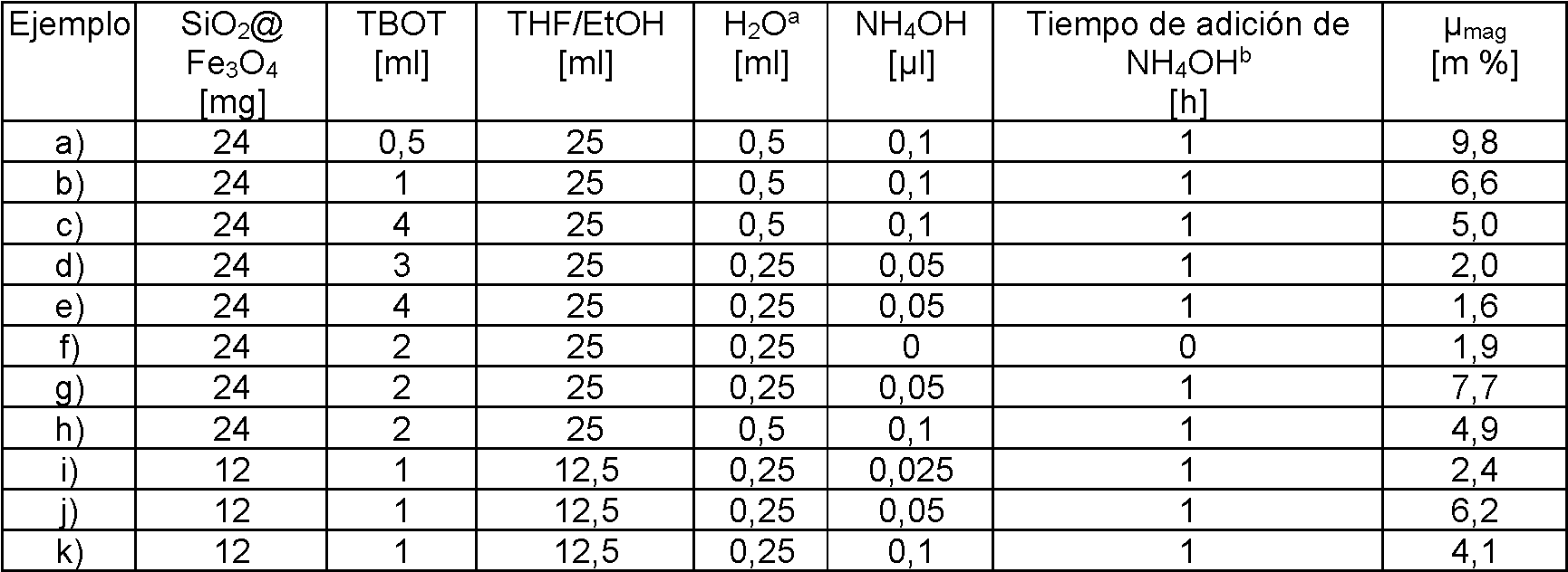
a: se añadió H2O una hora después de la adición de NH4OH.a: H2O was added one hour after the addition of NH4OH.
b: tiempo de adición de NH4OH después del comienzo de la adición de TBOTb: NH4OH addition time after start of TBOT addition
La figura 2 muestra imágenes SEM de las partículas de TiO2@SiO2@Fe3O4 producidas, mostrando la figura 2A las partículas obtenidas en el ejemplo 2f), la figura 2B las partículas obtenidas en el ejemplo 2h) y la figura 2C las partículas obtenidas en el ejemplo 2d). Se puede observar que llevar a cabo la segunda reacción de recubrimiento sin la adición de base da lugar a un recubrimiento de TiO2 con un morfología porosa sobre la superficie de SiO2 (figura 2A). Los resultados también muestran que la formación de partículas de TiO2 libres puede reducirse y la porosidad de las partículas recubiertas minimizarse si el catalizador de base se añade como pronto 60 minutos después del comienzo de la adición del material precursor de TiO2 (figura 2C).Figure 2 shows SEM images of the TiO2@SiO2@Fe3O4 particles produced, Figure 2A showing the particles obtained in Example 2f), Figure 2B the particles obtained in Example 2h) and Figure 2C the particles obtained in Example 2h). example 2d). It can be seen that carrying out the second coating reaction without the addition of base gives rise to a TiO2 coating with a porous morphology on the SiO2 surface (Figure 2A). The results also show that the formation of free TiO2 particles can be reduced and the porosity of the coated particles minimized if the base catalyst is added as early as 60 minutes after the start of the addition of the TiO2 precursor material (FIG. 2C).
La figura 3 muestra para dos concentraciones de bases diferentes (círculos: 0,014 mol/l de NH4OH; cuadrados: 0,029 mol/l) la influencia de la concentración de TBOT en el diámetro de partícula. La figura 4 muestra la influencia de la concentración de NH4OH para diferentes concentraciones de TBOT (círculos: 0,07 mol/l de TBOT; cuadrados: 0,17 de TBOT; triángulos: 0,29 mol/l) sobre el diámetro de partícula determinado por SEM. Tanto en la figura 3 como en la figura 4, la concentración de base se refiere al volumen final de la mezcla de reacción. Las líneas continuas sirven como ilustración en ambas figuras. Una concentración creciente de TBOT dio lugar a diámetros más grandes a una concentración de base moderada (0,014 mol/l), mientras que un aumento en la concentración de base dio como resultado diámetros de partículas más pequeños. Una concentración creciente de TBOT con una alta concentración de base en la mezcla de reacción puede dar lugar a la formación de partículas de TiO2 libres. Una concentración elevada de NH4OH (por ejemplo, 0,029 mol/l) puede dar lugar a la formación de grietas en las partículas producidas debido a la rápida hidrólisis de los restos de TBOT en la superficie de las partículas (véase también la figura 2B). Los mejores resultados de recubrimiento se obtuvieron a concentraciones de TBOT de 0,17 mol/l - 0,29 mol/l y concentraciones de base de 0,01 mol/l - 0,015 mol/l (véase la figura 2C). En comparación con partículas de TiO2@Fe3O4, es decir, partículas de Fe3O4 recubiertas solo con un recubrimiento de TiO2, las partículas magnéticas producidas presentan una apariencia visual neutra con respecto al color.Figure 3 shows for two different base concentrations (circles: 0.014 mol/l NH4OH; squares: 0.029 mol/l) the influence of the TBOT concentration on the particle diameter. Figure 4 shows the influence of the NH4OH concentration for different concentrations of TBOT (circles: 0.07 mol/l TBOT; squares: 0.17 TBOT; triangles: 0.29 mol/l) on the particle diameter. determined by SEM. In both Figure 3 and Figure 4, the base concentration refers to the final volume of the reaction mixture. Solid lines serve as illustration in both figures. An increasing concentration of TBOT resulted in larger diameters at moderate base concentration (0.014 mol/l), while an increase in base concentration resulted in smaller particle diameters. An increasing concentration of TBOT with a high concentration of base in the reaction mixture can lead to the formation of free TiO2 particles. A high concentration of NH4OH (eg 0.029 mol/l) can lead to crack formation in the produced particles due to rapid hydrolysis of TBOT residues on the surface of the particles (see also Figure 2B). The best coating results were obtained at TBOT concentrations of 0.17 mol/l - 0.29 mol/l and base concentrations of 0.01 mol/l - 0.015 mol/l (see Figure 2C). Compared to TiO2@Fe3O4 particles, ie Fe3O4 particles coated with only a TiO2 coating, the magnetic particles produced have a color-neutral visual appearance.
La figura 5 muestra la dependencia del diámetro de partícula del contenido magnético pmag de las partículas de TiO2@SiO2@Fe3O4. Se muestra que un contenido magnético de las partículas de TiO2@SiO2@Fe3O4 es inferior al 15,2%, el contenido magnético de las partículas de SiO2@Fe3O4 utilizadas como material de partida, y al disminuir el contenido magnético, el tamaño de partícula, básicamente, aumenta. Por lo tanto, se puede concluir que ha sido un recubrimiento exitoso. La línea continua representa la relación teórica entre el contenido magnético y el diámetro de partícula, que se describe mediante la ecuación siguiente: Figure 5 shows the particle diameter dependence of the pmag magnetic content of TiO2@SiO2@Fe3O4 particles. It is shown that a magnetic content of the TiO2@SiO2@Fe3O4 particles is less than 15.2%, the magnetic content of the SiO2@Fe3O4 particles used as starting material, and as the magnetic content decreases, the particle size basically increases. Therefore, it can be concluded that it has been a successful coating. The solid line represents the theoretical relationship between magnetic content and particle diameter, which is described by the following equation:

en la que p: densidad, m: masa, dm: diámetro del núcleo y D: diámetro de partícula de núcleo-cubierta, utilizándose en este caso como partículas de núcleo la partículas de SiO2@Fe3O4 y el resultado de la ecuación anterior se multiplica por jmag en porcentaje de partículas de núcleo de SiO2@Fe3O4 (15,2%) para ajustar la ecuación a la arquitectura de doble revestimiento.where p: density, m: mass, dm: core diameter and D: core-shell particle diameter, in this case using the SiO2@Fe3O4 particles as core particles and the result of the previous equation is multiplied by jmag in percentage of SiO2@Fe3O4 core particles (15.2%) to fit the equation to the double-clad architecture.
Ejemplo 2Example 2
Embebido de TiO2@SiO2@Fe3O4 en cemento dentalEmbedding of TiO2@SiO2@Fe3O4 in dental cement
Se embebieron partículas de TiO2@SiO2@Fe3O4 en cementos dentales para obtener materiales compuestos de cemento dental magnéticos. Como cemento dental se utilizó cemento dental de curado dual DC y lC (Variolink Esthetic DC/LC). Para producir los materiales compuestos se disolvieron o se dispersaron aproximadamente 0,25 g de cemento dental (LC) en 2 ml de EtOH en un vaso de borde redondeado oscurecido utilizando un baño ultrasónico. Se añadieron partículas de TiO2@SiO2@Fe3O4 y se dispersaron adicionalmente utilizando un baño ultrasónico a 70° C durante 30 min. La mezcla se secó en una cabina de secado. A continuación, se determinó el contenido magnético de los materiales compuestos utilizando mediciones VSM.TiO2@SiO2@Fe3O4 particles were embedded in dental cements to obtain magnetic dental cement composites. Dual curing DC and LC dental cement (Variolink Esthetic DC/LC) was used as dental cement. To produce the composites, approximately 0.25 g of dental cement (LC) was dissolved or dispersed in 2 mL of EtOH in a darkened beaker using an ultrasonic bath. TiO2@SiO2@Fe3O4 particles were added and further dispersed using an ultrasonic bath at 70°C for 30 min. The mixture was dried in a drying cabinet. The magnetic content of the composites was then determined using VSM measurements.
Las cantidades utilizadas de partículas de TiO2@SiO2@Fe3O4 y cemento dental así como el contenido magnético |Jmag de las partículas utilizadas y del material compuesto obtenido se muestran en la tabla siguiente:The quantities of TiO2@SiO2@Fe3O4 particles and dental cement used, as well as the magnetic content |Jmag of the particles used and of the composite material obtained, are shown in the following table:

Para los cuerpos de ensayo examinados en el ejemplo 3, el material compuesto de baja viscosidad se dispuso antes del curado entre dos portaobjetos, en cada caso con un disco metálico de 300 jm de espesor como espaciador en cada lado, de tal modo que se obtuvieron cuerpos de ensayo de aproximadamente 300 jm de espesor. El curado se realizó a la luz del día durante 6 horas.For the test bodies examined in Example 3, the low-viscosity composite material was placed before curing between two slides, in each case with a 300 µm thick metal disc as a spacer on each side, such that test bodies approximately 300 m thick. Curing was done in daylight for 6 hours.
Ejemplo 3Example 3
Propiedades ópticas de TiO2@SiO2@Fe3O4 en cemento dentalOptical properties of TiO2@SiO2@Fe3O4 in dental cement
Los materiales compuestos producidos según el ejemplo 2 se evaluaron con respecto a su aspecto visual. Para ello, se tomó una fotografía de los materiales compuestos frente a un fondo blanco/negro.The composite materials produced according to example 2 were evaluated with respect to their visual appearance. To do this, a photograph of the composite materials was taken against a black/white background.
La figura 6 muestra un diagrama con los resultados obtenidos en este caso. A este respecto, se registra el contenido magnético jmag del material compuesto frente al espesor de capa del revestimiento exterior 8702 de las partículas de TiO2@SiO2@Fe3O4, siendo el espesor de capa de TiO28702 la diferencia entre el diámetro de las partículas recubiertas con doble revestimiento Ti02@Si02@Fe304 y el diámetro de las partículas recubiertas con un solo revestimiento Si02Fe304. A este respecto, la posición de la fotografía en el diagrama representa aproximadamente las coordenadas correspondientes del contenido magnético del material compuesto (y, por lo tanto, el contenido de partículas del material compuesto) y el espesor del revestimiento de las partículas.Figure 6 shows a diagram with the results obtained in this case. In this regard, the magnetic content jmag of the composite material is plotted against the layer thickness of the outer coating 8702 of the TiO2@SiO2@Fe3O4 particles, the layer thickness of TiO28702 being the difference between the diameter of the double-coated particles Ti02@Si02@Fe304 coating and the diameter of the particles coated with a single Si02Fe304 coating. In this regard, the position of the photograph in the diagram roughly represents the corresponding coordinates of the magnetic content of the composite material (and thus the particle content of the composite material) and the thickness of the particle coating.
Además de las siete muestras del ejemplo 2, también se muestran en la figura 6 las fotografías de tres muestras que no contienen partículas de Ti02@Si02@Fe304 (espesor de capa del revestimiento exterior 8702 = 0 nm). De estas tres muestras, una no presentaba partículas magnéticas (jmag = 0 m %), las otras dos contenían diferentes cantidades de partículas de Si02@Fe304 para producir materiales compuestos con jmag = 0,02 m % y 0,12 m %. In addition to the seven samples from Example 2, photographs of three samples containing no Ti02@Si02@Fe304 particles (outer cladding layer thickness 8702 = 0 nm) are also shown in Figure 6 . Of these three samples, one did not present magnetic particles (jmag = 0 m%), the other two contained different amounts of Si02@Fe304 particles to produce composite materials with jmag = 0.02 m% and 0.12 m%.
Puede observarse en la figura 6 que el aumento del contenido magnético da lugar básicamente a materiales compuestos opacos y más oscuros. Los materiales compuestos magnéticos sin revestimiento de TO2 presentan, a este respecto, un color muy oscuro incluso con un contenido magnético de solo el 0,02 m %. La provisión de un revestimiento de TO2 alrededor de la partícula de Si02@Fe304, sin embargo, conduce a un apantallamiento de color eficaz del núcleo magnético de las partículas magnéticas. Mediante el aumento del espesor de capa de TO2, se puede mejorar aún más el apantallamiento de color del núcleo magnético, obteniéndose así materiales compuestos con colores más claros.It can be seen in figure 6 that the increase in magnetic content basically gives rise to darker and opaque composite materials. In this respect, magnetic composites without TO2 coating have a very dark color even with a magnetic content of only 0.02 m%. The provision of a TO2 coating around the Si02@Fe304 particle, however, leads to effective color screening of the magnetic core of the magnetic particles. By increasing the layer thickness of TO2, the color shielding of the magnetic core can be further improved, thus obtaining materials lighter colored compounds.
Ejemplo comparativo 1Comparative Example 1
Fabricación de núcleos de Fe3O4 con un recubrimiento de un solo revestimientoFabrication of Fe3O4 cores with a single cladding coating
En este ejemplo se describe la fabricación de núcleos de Fe3O4 con un recubrimiento de metacrilato de 3-(trimetoxisilil)propilo (TPM) polimerizado, ZrO2 o TO2. Las partículas recubiertas de esta forma también se denominan a continuación acrilato de SiO2@Fe3O4, ZrO2@Fe3O4 o TiO2@Fe3O4.This example describes the fabrication of Fe3O4 cores with a coating of polymerized 3-(trimethoxysilyl)propyl methacrylate (TPM), ZrO2, or TO2. Particles coated in this way are also referred to below as SiO2@Fe3O4, ZrO2@Fe3O4 or TiO2@Fe3O4 acrylate.
i) Fabricación de acrilato de SiO2@Fe3O4:i) Manufacture of SiO2@Fe3O4 acrylate:
Se dispusieron partículas de Fe3O4 magnéticas (cúbicas; diámetro promedio en número según TEM de 138 ± 31 nm) en un matraz de fondo redondo de tres bocas de 500 ml. Se añadió THF y la mezcla se dispersó en un baño ultrasónico (100%, 37 kHz) durante 10 min. Después se añadió EtOH y la mezcla se dispersó en un baño ultrasónico (100%, 37 kHz) durante 5 min. Después se añadió agua y la mezcla se dispersó en un baño ultrasónico (100%, 37 kHz) durante 5 minutos adicionales. Se añadió solución de amoniaco (25%) y la mezcla se dispersó en un baño ultrasónico (100%, 37 kHz) durante 5 min. A continuación, el matraz de fondo redondo de tres bocas se conectó a un agitador KPG (200 rpm) con una paleta de agitación de politetrafluoroetileno. Se añadió TPM gota a gota en atmósfera de gas protector (N2) y la mezcla se agitó durante 1 h. La polimerización de los restos de acrilato en el monómero binario se llevó a cabo utilizando ATRP (polimerización por radicales de transferencia de átomos). La dispersión de partículas se purgó con argón durante 20 minutos. A continuación, se añadió el catalizador Cu(I)Br y se purgó con argón durante 20 minutos adicionales. Se añadió el ligando PMDETA (N,N,N',N',N"-pentametildietilentriamina) para formar el complejo catalizador-ligando. Después de agitar durante 20 min en atmósfera de argón a temperatura ambiente, se añadió el iniciador MBrP (2-bromopropionato de metilo), siendo la relación molar de TPM:Cu(I)Br:PMDETA:MBrP de 50:1:1:2. La polimerización se llevó a cabo en atmósfera de gas protector Después de 3 h se lavaron las partículas cinco veces con aproximadamente 15 ml de EtOH y se separaron magnéticamente con un imán 400 mT para separar la sílice libre. A continuación, las partículas magnéticas libres se separaron magnéticamente con un imán de aproximadamente 100 mT Las partículas de núcleo-cubierta, finalmente, se secaron al vacío a 85° C y el contenido magnético se determinó por medio de mediciones VSM.Magnetic Fe 3 O 4 particles (cubic; TEM number average diameter 138 ± 31 nm) were placed in a 500 mL 3-necked round bottom flask. THF was added and the mixture was dispersed in an ultrasonic bath (100%, 37 kHz) for 10 min. EtOH was then added and the mixture was dispersed in an ultrasonic bath (100%, 37 kHz) for 5 min. Water was then added and the mixture was dispersed in an ultrasonic bath (100%, 37 kHz) for an additional 5 minutes. Ammonia solution (25%) was added and the mixture was dispersed in an ultrasonic bath (100%, 37 kHz) for 5 min. The three neck round bottom flask was then connected to a KPG stirrer (200 rpm) with a polytetrafluoroethylene stirring blade. TPM was added dropwise under protective gas (N2) and the mixture was stirred for 1 h. Polymerization of the acrylate moieties in the binary monomer was carried out using ATRP (Atom Transfer Radical Polymerization). The particle dispersion was purged with argon for 20 minutes. The Cu(I)Br catalyst was then added and purged with argon for an additional 20 minutes. The ligand PMDETA (N,N,N',N',N"-pentamethyldiethylenetriamine) was added to form the catalyst-ligand complex. After stirring for 20 min under argon at room temperature, the initiator MBrP (2 -methyl bromopropionate), with the molar ratio of TPM:Cu(I)Br:PMDETA:MBrP being 50:1:1:2.The polymerization was carried out in a protective gas atmosphere.After 3 h, the particles were washed. five times with about 15 mL EtOH and magnetically separated with a 400 mT magnet to remove free silica, then the free magnetic particles were magnetically separated with a about 100 mT magnet. vacuum dried at 85°C and the magnetic content was determined by VSM measurements.

a: medido con VSMa: measured with VSM
ii) Fabricación de ZrO@Fe3O4ii) Fabrication of ZrO@Fe3O4
Se dispersaron partículas de Fe3O4 magnéticas (cúbicas; diámetro promedio en número según TEM de 226 ± 77 nm) en 20 ml de EtOH en un matraz de fondo redondo de tres bocas de 100 ml con un baño ultrasónico durante 5 min. Se añadieron amoniaco (NH4OH, 25%) y 62,5 j l de agua y se dispersaron durante 5 min adicionales. Paralelamente, el matraz de fondo redondo de tres bocas se conectó a un agitador KPG (200 rpm). Se retiró el baño ultrasónico y, utilizando una bomba de jeringa, se añadió gota a gota tetrabutanolato de circonio (TBOZ) en atmósfera de gas protector (N2) a la dispersión de partículas a temperatura ambiente. Después de la adición de TBOZ, la dispersión de partículas se agitó durante una hora. A continuación, las partículas se lavaron cinco veces con 15 ml de EtOH y se separaron magnéticamente.Magnetic Fe 3 O 4 particles (cubic; TEM number average diameter 226 ± 77 nm) were dispersed in 20 mL EtOH in a 100 mL 3-neck round-bottom flask with an ultrasonic bath for 5 min. Ammonia (NH4OH, 25%) and 62.5 jL of water were added and dispersed for an additional 5 min. In parallel, the three necked round bottom flask was connected to a KPG stirrer (200 rpm). The ultrasonic bath was removed and, using a syringe pump, zirconium tetrabutanolate (TBOZ) was added dropwise under protective gas (N2) to the particle dispersion at room temperature. After the addition of TBOZ, the particle dispersion was stirred for one hour. The particles were then washed five times with 15 mL EtOH and magnetically separated.
Las cantidades utilizadas de partículas de Fe3O4, TBOZ, EtOH, agua y NH4OH y el contenido magnético |j¡mag de las partículas de ZrO2@Fe3O4 obtenidas se muestran en la tabla siguiente:The quantities of Fe3O4, TBOZ, EtOH, water and NH4OH particles used and the magnetic content |j¡mag of the ZrO2@Fe3O4 particles obtained are shown in the following table:

a: medido mediante VSMa: measured by VSM
iii) Fabricación de TiO@Fe3O4iii) Fabrication of TiO@Fe3O4
Se dispersaron partículas de Fe3O4 magnéticas (cúbicas; diámetro promedio en número según TEM de 226 ± 77 nm) en THF/EtOH (1:4 v/v) durante 5 min en un matraz de fondo redondo de tres bocas de 100 ml con baño ultrasónico. Se añadieron amoniaco (NH4OH, 25%) y 500 j l de agua y se dispersaron durante 5 min adicionales. Por medio de una bomba de jeringa, se añadió gota a gota TBOT diluido en 20 ml de EtOH en atmósfera de gas protector (N2) a la dispersión de partículas a temperatura ambiente. Después de la adición de TBOT, la dispersión de partículas se agitó durante una hora. Después, las partículas se lavaron cinco veces con aproximadamente 15 ml de EtOH cada vez, se separaron magnéticamente y se secaron al vacío.Magnetic Fe3O4 particles (cubic; TEM number-average diameter 226 ± 77 nm) were dispersed in THF/EtOH (1:4 v/v) for 5 min in a 100 mL 3-necked round-bottom flask with bath. ultrasonic. Ammonia (NH4OH, 25%) and 500 µl of water were added and dispersed for an additional 5 min. By means of a syringe pump, TBOT diluted in 20 mL EtOH under protective gas (N2) atmosphere was added dropwise to the particle dispersion at room temperature. After the addition of TBOT, the particle dispersion was stirred for one hour. The particles were then washed five times with approx. 15 mL of EtOH each time, magnetically separated and dried in vacuo.
Las cantidades utilizadas de partículas de Fe3O4, TBOT, EtOH y NH4OH y el contenido magnético Mmag de las partículas de TiO2@Fe3O4 obtenidas se muestran en la tabla siguiente:The quantities of Fe3O4, TBOT, EtOH and NH4OH particles used and the magnetic content Mmag of the TiO2@Fe3O4 particles obtained are shown in the following table:

a: medido mediante VSMa: measured by VSM
Ejemplo comparativo 2Comparative Example 2
Propiedades ópticas de núcleos de Fe3O4 con recubrimiento de un solo revestimientoOptical properties of single-clad coated Fe3O4 cores
La influencia de los diversos materiales de revestimiento sobre las propiedades ópticas de las partículas magnéticas se muestra en la figura 7. Las imágenes (a) muestran partículas de acrilato de SiO2@Fe3O4 en el aire (izquierda) y partículas de acrilato de SiO2@Fe3O4 embebidas en cemento dental (derecha). Las imágenes (b) muestran partículas de ZrO2@Fe3O4 en el aire (izquierda) y partículas de ZrO2@Fe3O4 embebidas en cemento dental (derecha). Las imágenes (c) muestran partículas de TiO2@Fe3O4 en el aire (izquierda) y partículas de TiO2@Fe3O4 embebidas en cemento dental (derecha). El índice de refracción del recubrimiento de acrilato de SO2 es de aproximadamente 1,5, mientras que ZrO2 presenta un índice de refracción de 2,18 y TO2 presenta un índice de refracción de 2,58.The influence of the various coating materials on the optical properties of the magnetic particles is shown in Figure 7. Images (a) show SiO2@Fe3O4 acrylate particles in air (left) and SiO2@Fe3O4 acrylate particles embedded in dental cement (right). Images (b) show ZrO2@Fe3O4 particles in air (left) and ZrO2@Fe3O4 particles embedded in dental cement (right). Images (c) show TiO2@Fe3O4 particles in air (left) and TiO2@Fe3O4 particles embedded in dental cement (right). The refractive index of the SO2 acrylate coating is about 1.5, while ZrO2 has a refractive index of 2.18 and TO2 has a refractive index of 2.58.
Mientras que las partículas de acrilato de SiO2@Fe3O4 en el aire presentaban un color casi neutro con un tono gris levemente claro, las partículas de ZrO2@Fe3O4 mostraban en el aire un color gris y las partículas de TiO2@Fe3O4 mostraban en el aire un color casi negro.While SiO2@Fe3O4 acrylate particles in air had an almost neutral color with a slightly light gray tint, ZrO2@Fe3O4 particles in air showed a gray color and TiO2@Fe3O4 particles in air showed a light gray color. almost black colour.
A continuación, una parte de las partículas magnéticas se embebieron en cemento dental. Para este fin, las partículas magnéticas recubiertas se introdujeron en cemento dental (DC) a una concentración del 1% en peso y se mantuvieron durante aproximadamente 10 minutos en un agitador de vórtice a máxima potencia hasta que el cemento dental se solidificara.Next, a part of the magnetic particles was embedded in dental cement. For this purpose, the coated magnetic particles were introduced into dental cement (DC) at a concentration of 1% by weight and kept for approximately 10 minutes in a vortex mixer at maximum power until the dental cement solidified.
En la figura 7 se puede observar que el acrilato de SiO2@Fe3O4 mostró un color significativamente más oscuro en la matriz del cemento dental que en contacto con el aire. Esta observación también se aplica a ZrO2@Fe3O4 y TiO2@Fe3O4. A este respecto, cabe señalar que el borde blanco que se puede observar en las imágenes de las muestras de cemento dental se debe a la superficie brillante del cemento dental y por lo tanto a los reflejos y no a los efectos del recubrimiento de las partículas magnéticas.In Figure 7 it can be seen that the SiO2@Fe3O4 acrylate showed a significantly darker color in the dental cement matrix than in contact with air. This observation also applies to ZrO2@Fe3O4 and TiO2@Fe3O4. In this regard, it should be noted that the white edge that can be observed in the images of dental cement samples is due to the shiny surface of the dental cement and therefore due to reflections and not due to the coating effects of the magnetic particles. .
Las observaciones anteriores muestran que el contraste del índice de refracción entre el material de revestimiento y la matriz circundante desempeña un papel decisivo en el aspecto visual. Esto también se ilustra en la figura 8, que muestra una imagen de partículas de acrilato de SiO2@Fe3O4 que están dispersadas en diferentes medios con diferentes índices de refracción, utilizándose los siguientes medios de izquierda a derecha (en cada caso con datos sobre su índice de refracción n): (a) poliestireno (n = 1,58), (b) o-xileno (n = 1,50), (c) poli(metacrilato de metilo) (n = 1,49), (d) 1,4-dioxano (n = ,42), (e) etanol (n = 1,37), (f) agua (n = 1,33), (g) ácido trifluoroacético (n = 1,28) y (h) aire (n = 1,00). Puede observarse que el color de la dispersión se oscurece con el aumento del índice de refracción del disolvente, hasta que parece alcanzar un máximo con un índice de refracción de 1,49.The above observations show that the refractive index contrast between the coating material and the surrounding matrix plays a decisive role in the visual appearance. This is also illustrated in Figure 8, which shows an image of SiO2@Fe3O4 acrylate particles that are dispersed in different media with different refractive indices, using the following media from left to right (in each case with data on their index of refraction n): (a) polystyrene (n = 1.58), (b) o-xylene (n = 1.50), (c) poly(methyl methacrylate) (n = 1.49), (d ) 1,4-dioxane (n = 0.42), (e) ethanol (n = 1.37), (f) water (n = 1.33), (g) trifluoroacetic acid (n = 1.28) and (h) air (n = 1.00). It can be seen that the color of the dispersion darkens with increasing refractive index of the solvent, until it appears to reach a maximum at a refractive index of 1.49.
Ejemplo 4Example 4
Este ejemplo describe el análisis de partículas utilizando mediciones VSM, mediciones TEM y mediciones SEM. This example describes particle analysis using VSM measurements, TEM measurements, and SEM measurements.
Mediciones VSMVSM measurements
Las propiedades magnéticas de las muestras obtenidas en el presente documento se analizaron utilizando un magnetómetro de muestra vibrante (VSM) EV7 de la empresa ADE Magnetics. La magnetización de una muestra se midió en función del campo aplicado, estando la muestra en oscilación perpendicularmente a un campo de magnetización uniforme. La intensidad de campo máxima del electroimán (3472-10 GMW) de la empresa Magnet Systems utilizado fue de 2,1 T La muestra se sometió a una frecuencia de oscilación de 75 Hz y los ciclos de histéresis se registraron entre -1,5-10® A-m-1 y 1,5-10® A-m-1.The magnetic properties of the samples obtained herein were analyzed using an EV7 Vibrating Sample Magnetometer (VSM) from ADE Magnetics. The magnetization of a sample was measured as a function of the applied field, with the sample oscillating perpendicular to a uniform magnetizing field. The maximum field intensity of the electromagnet (3472-10 GMW) from the Magnet Systems company used was 2.1 T. The sample was subjected to an oscillation frequency of 75 Hz and the hysteresis cycles were recorded between -1.5- 10® Am-1 and 1.5-10® Am-1.
Mediciones TEMTEM measurements
Las mediciones TEM se llevaron a cabo en un Leo 912 Omega de la empresa Zeiss. Para este fin, las muestras de una dispersión de partículas se dispusieron gota a gota sobre una rejilla de cobre recubierta de carbono antes de las mediciones y las muestras se secaron a temperatura ambiente. Las imágenes se evaluaron con el programa informático SiViewer y el programa informático ImageJ.TEM measurements were carried out on a Leo 912 Omega from the company Zeiss. For this purpose, samples of a particle dispersion were placed dropwise on a carbon-coated copper grid before of the measurements and the samples were dried at room temperature. Images were evaluated with SiViewer software and ImageJ software.
Mediciones SEMSEM measurements
Las imágenes SEM se generaron con un microscopio electrónico de barrido Zeiss Neon 40 ESB CrossBeam FIB-SEM. Las muestras se dispusieron gota a gota a partir de una dispersión de partículas sobre una placa de sílice. Las muestras se recubrieron con oro antes de la medición. El tamaño de partícula se evaluó después de la medición con el programa informático ImageJ. SEM images were generated with a Zeiss Neon 40 ESB CrossBeam FIB-SEM scanning electron microscope. The samples were placed dropwise from a dispersion of particles on a silica plate. The samples were plated with gold before measurement. The particle size was evaluated after measurement with ImageJ software.
Claims (10)
Applications Claiming Priority (1)
| Application Number | Priority Date | Filing Date | Title |
|---|---|---|---|
| EP18193477.9A EP3621089B1 (en) | 2018-09-10 | 2018-09-10 | Dental material with magnetic particles with improved colour shielding |
Publications (1)
| Publication Number | Publication Date |
|---|---|
| ES2898224T3 true ES2898224T3 (en) | 2022-03-04 |
Family
ID=63578974
Family Applications (1)
| Application Number | Title | Priority Date | Filing Date |
|---|---|---|---|
| ES18193477T Active ES2898224T3 (en) | 2018-09-10 | 2018-09-10 | Dental material with magnetic particles with improved color screening |
Country Status (3)
| Country | Link |
|---|---|
| US (1) | US11596582B2 (en) |
| EP (1) | EP3621089B1 (en) |
| ES (1) | ES2898224T3 (en) |
Family Cites Families (15)
| Publication number | Priority date | Publication date | Assignee | Title |
|---|---|---|---|---|
| US5194356A (en) | 1990-11-05 | 1993-03-16 | Xerox Corporation | Toner compositions |
| DE4117782C2 (en) | 1991-05-28 | 1997-07-17 | Diagnostikforschung Inst | Nanocrystalline magnetic iron oxide particles, processes for their production and diagnostic and / or therapeutic agents |
| CA2114913C (en) * | 1993-02-05 | 2003-12-09 | Takafumi Atarashi | Powder having at least one layer and process for preparing the same |
| JP3032927B2 (en) * | 1993-02-05 | 2000-04-17 | 日鉄鉱業株式会社 | Metal or metal compound powder having a metal oxide film on the surface |
| JPH1060304A (en) * | 1996-08-23 | 1998-03-03 | Nittetsu Mining Co Ltd | Additive pigment powder |
| JP2000150218A (en) | 1998-11-09 | 2000-05-30 | Ube Ind Ltd | White-based magnetic powder and its manufacture |
| JP4660678B2 (en) | 2001-06-18 | 2011-03-30 | 三井金属鉱業株式会社 | White magnetic powder and method for producing the same |
| US20100063263A1 (en) | 2005-06-23 | 2010-03-11 | Siemens Medical Solutions Diagnostics Gmbh | Magnetic particles with a closed ultrathin silica layer, method for the production thereof and their use |
| WO2010149150A2 (en) | 2009-06-22 | 2010-12-29 | Deklatec Gmbh | Colorless, magnetic polymer particles for highly sensitive detection of biological substances and pathogens within the context of bioanalytics and diagnostics |
| WO2013034778A2 (en) | 2011-09-08 | 2013-03-14 | Ivoclar Vivadent Ag | Dental materials based on compounds having debonding-on-demand properties |
| KR101341150B1 (en) * | 2011-12-22 | 2013-12-11 | 한국조폐공사 | Magnetic Particle Having High reflection protected layer and the Fabrication Method Thereof |
| KR20150060337A (en) * | 2013-11-26 | 2015-06-03 | 삼성전기주식회사 | Composite powder, pigment paste using the same and touch sensor |
| EP2965740A1 (en) | 2014-07-11 | 2016-01-13 | Ivoclar Vivadent AG | Dental materials with debonding on demand properties |
| EP3081601A1 (en) * | 2015-04-15 | 2016-10-19 | Schlenk Metallic Pigments GmbH | Pearlescent pigments based on monolithic substrates |
| DE102015118816A1 (en) | 2015-11-03 | 2017-05-04 | Fraunhofer-Gesellschaft zur Förderung der angewandten Forschung e.V. | Superparamagnetic platelets composed of nanomagnetite-silica composite needles, with optical color effects in dispersion |
-
2018
- 2018-09-10 ES ES18193477T patent/ES2898224T3/en active Active
- 2018-09-10 EP EP18193477.9A patent/EP3621089B1/en active Active
-
2019
- 2019-08-16 US US16/542,408 patent/US11596582B2/en active Active
Also Published As
| Publication number | Publication date |
|---|---|
| US20200078271A1 (en) | 2020-03-12 |
| US11596582B2 (en) | 2023-03-07 |
| EP3621089A1 (en) | 2020-03-11 |
| EP3621089B1 (en) | 2021-08-25 |
Similar Documents
| Publication | Publication Date | Title |
|---|---|---|
| Blanco-Andujar et al. | Design of iron oxide-based nanoparticles for MRI and magnetic hyperthermia | |
| Patsula et al. | Superparamagnetic Fe3O4 nanoparticles: synthesis by thermal decomposition of iron (III) glucuronate and application in magnetic resonance imaging | |
| Genchi et al. | Barium titanate nanoparticles: promising multitasking vectors in nanomedicine | |
| Iannotti et al. | Fe-doping-induced magnetism in nano-hydroxyapatites | |
| Ahrén et al. | Synthesis and characterization of PEGylated Gd2O3 nanoparticles for MRI contrast enhancement | |
| Bohara et al. | Cancer cell extinction through a magnetic fluid hyperthermia treatment produced by superparamagnetic Co–Zn ferrite nanoparticles | |
| Duguet et al. | Magnetic nanoparticles and their applications in medicine | |
| Yang et al. | Recyclable Fe3O4/hydroxyapatite composite nanoparticles for photocatalytic applications | |
| Leal et al. | Effect of the surface treatment on the structural, morphological, magnetic and biological properties of MFe2O4 iron spinels (M= Cu, Ni, Co, Mn and Fe) | |
| Zahraei et al. | Versatile theranostics agents designed by coating ferrite nanoparticles with biocompatible polymers | |
| Sabouri et al. | Fe3O4/bioactive glass nanostructure: a promising therapeutic platform for osteosarcoma treatment | |
| ES2898224T3 (en) | Dental material with magnetic particles with improved color screening | |
| Coelho et al. | Maghemite–gold core–shell nanostructures (γ-Fe 2 O 3@ Au) surface-functionalized with aluminium phthalocyanine for multi-task imaging and therapy | |
| Fudimura et al. | Synthesis and characterization of methylene blue-containing silica-coated magnetic nanoparticles for photodynamic therapy | |
| Borgohain et al. | A new CoFe 2 O 4–Cr 2 O 3–SiO 2 fluorescent magnetic nanocomposite | |
| Wong et al. | Magnetic nanoparticle–polyelectrolyte interaction: a layered approach for biomedical applications | |
| JP5670094B2 (en) | Method for producing magnetite nanoparticles | |
| Sneha et al. | Radiopacity endowed magnetic nanocomposite with hyperthermia and in vitro mineralization potential: A combinatorial therapeutic system for osteosarcoma | |
| CA2684964C (en) | Magnetically deformable ferrofluids and mirrors | |
| Kataoka et al. | Coordination State Control of Citric Acid Molecules on Europium (III) Ion-Doped Hydroxyapatite Nanoparticles for Highly Efficient Photoluminescence toward Biomedical Applications | |
| Gavilán et al. | Controlling the size and shape of uniform magnetic iron oxide nanoparticles for biomedical applications | |
| US20120220048A1 (en) | Magnetic marker particle and method for producing the same | |
| ES2657967T3 (en) | Magnetite in the form of nanoparticles | |
| Muzquiz-Ramos et al. | In vitro bonelike apatite formation on magnetite nanoparticles after a calcium silicate treatment: Preparation, characterization and hemolysis studies | |
| Sneha et al. | Natural rubber latex assisted shape-attuned synthesis of intrinsically radiopaque and magnetic bioceramic nanocomposite with hyperthermia potential for cancer therapeutics |