ES2860927T3 - New geometries of tangential flow separation multichannel tubular elements that integrate turbulence promoters and manufacturing process - Google Patents
New geometries of tangential flow separation multichannel tubular elements that integrate turbulence promoters and manufacturing process Download PDFInfo
- Publication number
- ES2860927T3 ES2860927T3 ES15753393T ES15753393T ES2860927T3 ES 2860927 T3 ES2860927 T3 ES 2860927T3 ES 15753393 T ES15753393 T ES 15753393T ES 15753393 T ES15753393 T ES 15753393T ES 2860927 T3 ES2860927 T3 ES 2860927T3
- Authority
- ES
- Spain
- Prior art keywords
- support
- channels
- obstacles
- tangential flow
- layer
- Prior art date
- Legal status (The legal status is an assumption and is not a legal conclusion. Google has not performed a legal analysis and makes no representation as to the accuracy of the status listed.)
- Active
Links
- 238000000926 separation method Methods 0.000 title claims abstract description 47
- 238000004519 manufacturing process Methods 0.000 title claims description 24
- 239000012530 fluid Substances 0.000 claims abstract description 42
- 239000000463 material Substances 0.000 claims abstract description 31
- 238000001914 filtration Methods 0.000 claims abstract description 21
- 239000012465 retentate Substances 0.000 claims abstract description 8
- 239000000706 filtrate Substances 0.000 claims abstract description 7
- 239000010410 layer Substances 0.000 claims description 81
- 239000000843 powder Substances 0.000 claims description 66
- 238000000034 method Methods 0.000 claims description 45
- 239000011148 porous material Substances 0.000 claims description 37
- 239000000919 ceramic Substances 0.000 claims description 16
- 238000009826 distribution Methods 0.000 claims description 16
- 239000000203 mixture Substances 0.000 claims description 15
- 239000002243 precursor Substances 0.000 claims description 11
- 239000007787 solid Substances 0.000 claims description 11
- 238000007596 consolidation process Methods 0.000 claims description 9
- 239000012943 hotmelt Substances 0.000 claims description 9
- 239000000654 additive Substances 0.000 claims description 7
- 230000000996 additive effect Effects 0.000 claims description 7
- 229910010293 ceramic material Inorganic materials 0.000 claims description 7
- 230000008018 melting Effects 0.000 claims description 7
- 238000002844 melting Methods 0.000 claims description 7
- 229920000620 organic polymer Polymers 0.000 claims description 7
- 150000004767 nitrides Chemical class 0.000 claims description 6
- 230000035515 penetration Effects 0.000 claims description 6
- QSHDDOUJBYECFT-UHFFFAOYSA-N mercury Chemical compound [Hg] QSHDDOUJBYECFT-UHFFFAOYSA-N 0.000 claims description 5
- 229910052753 mercury Inorganic materials 0.000 claims description 5
- GWEVSGVZZGPLCZ-UHFFFAOYSA-N Titan oxide Chemical compound O=[Ti]=O GWEVSGVZZGPLCZ-UHFFFAOYSA-N 0.000 claims description 4
- 229910010272 inorganic material Inorganic materials 0.000 claims description 4
- 239000011147 inorganic material Substances 0.000 claims description 4
- 239000012705 liquid precursor Substances 0.000 claims description 4
- OGIDPMRJRNCKJF-UHFFFAOYSA-N titanium oxide Inorganic materials [Ti]=O OGIDPMRJRNCKJF-UHFFFAOYSA-N 0.000 claims description 4
- 150000001247 metal acetylides Chemical class 0.000 claims description 3
- 229910052582 BN Inorganic materials 0.000 claims description 2
- PZNSFCLAULLKQX-UHFFFAOYSA-N Boron nitride Chemical compound N#B PZNSFCLAULLKQX-UHFFFAOYSA-N 0.000 claims description 2
- NRTOMJZYCJJWKI-UHFFFAOYSA-N Titanium nitride Chemical compound [Ti]#N NRTOMJZYCJJWKI-UHFFFAOYSA-N 0.000 claims description 2
- QCWXUUIWCKQGHC-UHFFFAOYSA-N Zirconium Chemical compound [Zr] QCWXUUIWCKQGHC-UHFFFAOYSA-N 0.000 claims description 2
- PNEYBMLMFCGWSK-UHFFFAOYSA-N aluminium oxide Inorganic materials [O-2].[O-2].[O-2].[Al+3].[Al+3] PNEYBMLMFCGWSK-UHFFFAOYSA-N 0.000 claims description 2
- PMHQVHHXPFUNSP-UHFFFAOYSA-M copper(1+);methylsulfanylmethane;bromide Chemical compound Br[Cu].CSC PMHQVHHXPFUNSP-UHFFFAOYSA-M 0.000 claims description 2
- 239000012044 organic layer Substances 0.000 claims description 2
- 239000011368 organic material Substances 0.000 claims description 2
- HBMJWWWQQXIZIP-UHFFFAOYSA-N silicon carbide Chemical compound [Si+]#[C-] HBMJWWWQQXIZIP-UHFFFAOYSA-N 0.000 claims description 2
- 229910010271 silicon carbide Inorganic materials 0.000 claims description 2
- 229910052726 zirconium Inorganic materials 0.000 claims description 2
- 239000012528 membrane Substances 0.000 description 23
- 235000013339 cereals Nutrition 0.000 description 20
- 239000007788 liquid Substances 0.000 description 19
- 238000005245 sintering Methods 0.000 description 17
- 239000011230 binding agent Substances 0.000 description 14
- 239000000725 suspension Substances 0.000 description 12
- 239000002245 particle Substances 0.000 description 9
- 238000001125 extrusion Methods 0.000 description 8
- 238000000151 deposition Methods 0.000 description 6
- 238000001471 micro-filtration Methods 0.000 description 6
- 230000008569 process Effects 0.000 description 6
- 238000000110 selective laser sintering Methods 0.000 description 6
- 238000000108 ultra-filtration Methods 0.000 description 5
- 238000010894 electron beam technology Methods 0.000 description 4
- 238000001033 granulometry Methods 0.000 description 4
- 238000001728 nano-filtration Methods 0.000 description 4
- 230000002093 peripheral effect Effects 0.000 description 4
- 230000035699 permeability Effects 0.000 description 4
- 239000012466 permeate Substances 0.000 description 4
- 229920005989 resin Polymers 0.000 description 4
- 239000011347 resin Substances 0.000 description 4
- 239000000126 substance Substances 0.000 description 4
- 238000010146 3D printing Methods 0.000 description 3
- 239000011248 coating agent Substances 0.000 description 3
- 238000000576 coating method Methods 0.000 description 3
- 230000008021 deposition Effects 0.000 description 3
- 238000001035 drying Methods 0.000 description 3
- 239000000428 dust Substances 0.000 description 3
- 230000004927 fusion Effects 0.000 description 3
- 238000005259 measurement Methods 0.000 description 3
- 238000000691 measurement method Methods 0.000 description 3
- 239000012071 phase Substances 0.000 description 3
- 230000010287 polarization Effects 0.000 description 3
- 230000000717 retained effect Effects 0.000 description 3
- 238000012546 transfer Methods 0.000 description 3
- XLYOFNOQVPJJNP-UHFFFAOYSA-N water Substances O XLYOFNOQVPJJNP-UHFFFAOYSA-N 0.000 description 3
- YLQBMQCUIZJEEH-UHFFFAOYSA-N Furan Chemical compound C=1C=COC=1 YLQBMQCUIZJEEH-UHFFFAOYSA-N 0.000 description 2
- 241000209094 Oryza Species 0.000 description 2
- 235000007164 Oryza sativa Nutrition 0.000 description 2
- 238000009825 accumulation Methods 0.000 description 2
- 230000003213 activating effect Effects 0.000 description 2
- 239000012190 activator Substances 0.000 description 2
- 230000015572 biosynthetic process Effects 0.000 description 2
- 239000003795 chemical substances by application Substances 0.000 description 2
- 239000006185 dispersion Substances 0.000 description 2
- 238000010304 firing Methods 0.000 description 2
- 239000007789 gas Substances 0.000 description 2
- 238000010438 heat treatment Methods 0.000 description 2
- 230000003993 interaction Effects 0.000 description 2
- 229920002521 macromolecule Polymers 0.000 description 2
- 229910044991 metal oxide Inorganic materials 0.000 description 2
- 150000004706 metal oxides Chemical class 0.000 description 2
- 235000009566 rice Nutrition 0.000 description 2
- 238000007493 shaping process Methods 0.000 description 2
- 239000002356 single layer Substances 0.000 description 2
- 239000002904 solvent Substances 0.000 description 2
- 238000001179 sorption measurement Methods 0.000 description 2
- 238000011282 treatment Methods 0.000 description 2
- 238000011144 upstream manufacturing Methods 0.000 description 2
- 229910010413 TiO 2 Inorganic materials 0.000 description 1
- 230000009471 action Effects 0.000 description 1
- 229920003180 amino resin Polymers 0.000 description 1
- 230000004888 barrier function Effects 0.000 description 1
- 230000008901 benefit Effects 0.000 description 1
- 230000000903 blocking effect Effects 0.000 description 1
- 238000012662 bulk polymerization Methods 0.000 description 1
- 238000004140 cleaning Methods 0.000 description 1
- 150000001875 compounds Chemical class 0.000 description 1
- 239000000470 constituent Substances 0.000 description 1
- 238000010276 construction Methods 0.000 description 1
- 238000005336 cracking Methods 0.000 description 1
- 238000000280 densification Methods 0.000 description 1
- 239000003599 detergent Substances 0.000 description 1
- 238000009792 diffusion process Methods 0.000 description 1
- 239000003651 drinking water Substances 0.000 description 1
- 235000020188 drinking water Nutrition 0.000 description 1
- 230000000694 effects Effects 0.000 description 1
- 230000005686 electrostatic field Effects 0.000 description 1
- 230000008030 elimination Effects 0.000 description 1
- 238000003379 elimination reaction Methods 0.000 description 1
- 238000005516 engineering process Methods 0.000 description 1
- 239000008246 gaseous mixture Substances 0.000 description 1
- 239000007792 gaseous phase Substances 0.000 description 1
- 238000000227 grinding Methods 0.000 description 1
- 239000003295 industrial effluent Substances 0.000 description 1
- 239000010954 inorganic particle Substances 0.000 description 1
- 230000001788 irregular Effects 0.000 description 1
- 230000007246 mechanism Effects 0.000 description 1
- 229910052751 metal Inorganic materials 0.000 description 1
- 239000002184 metal Substances 0.000 description 1
- 238000000386 microscopy Methods 0.000 description 1
- 238000012986 modification Methods 0.000 description 1
- 230000004048 modification Effects 0.000 description 1
- 239000006259 organic additive Substances 0.000 description 1
- 230000003204 osmotic effect Effects 0.000 description 1
- 230000000737 periodic effect Effects 0.000 description 1
- ISWSIDIOOBJBQZ-UHFFFAOYSA-N phenol group Chemical group C1(=CC=CC=C1)O ISWSIDIOOBJBQZ-UHFFFAOYSA-N 0.000 description 1
- 239000004033 plastic Substances 0.000 description 1
- 229920000642 polymer Polymers 0.000 description 1
- 238000006116 polymerization reaction Methods 0.000 description 1
- 230000036619 pore blockages Effects 0.000 description 1
- 238000002360 preparation method Methods 0.000 description 1
- 238000007639 printing Methods 0.000 description 1
- 230000009467 reduction Effects 0.000 description 1
- 238000000518 rheometry Methods 0.000 description 1
- 238000005070 sampling Methods 0.000 description 1
- 238000004626 scanning electron microscopy Methods 0.000 description 1
- 238000004513 sizing Methods 0.000 description 1
- 238000007711 solidification Methods 0.000 description 1
- 230000008023 solidification Effects 0.000 description 1
- 238000005507 spraying Methods 0.000 description 1
- 230000003746 surface roughness Effects 0.000 description 1
- 229920001187 thermosetting polymer Polymers 0.000 description 1
- 210000003462 vein Anatomy 0.000 description 1
Classifications
-
- B—PERFORMING OPERATIONS; TRANSPORTING
- B01—PHYSICAL OR CHEMICAL PROCESSES OR APPARATUS IN GENERAL
- B01D—SEPARATION
- B01D63/00—Apparatus in general for separation processes using semi-permeable membranes
- B01D63/06—Tubular membrane modules
-
- B—PERFORMING OPERATIONS; TRANSPORTING
- B01—PHYSICAL OR CHEMICAL PROCESSES OR APPARATUS IN GENERAL
- B01D—SEPARATION
- B01D61/00—Processes of separation using semi-permeable membranes, e.g. dialysis, osmosis or ultrafiltration; Apparatus, accessories or auxiliary operations specially adapted therefor
- B01D61/14—Ultrafiltration; Microfiltration
- B01D61/18—Apparatus therefor
-
- B—PERFORMING OPERATIONS; TRANSPORTING
- B01—PHYSICAL OR CHEMICAL PROCESSES OR APPARATUS IN GENERAL
- B01D—SEPARATION
- B01D63/00—Apparatus in general for separation processes using semi-permeable membranes
- B01D63/06—Tubular membrane modules
- B01D63/061—Manufacturing thereof
-
- B—PERFORMING OPERATIONS; TRANSPORTING
- B01—PHYSICAL OR CHEMICAL PROCESSES OR APPARATUS IN GENERAL
- B01D—SEPARATION
- B01D63/00—Apparatus in general for separation processes using semi-permeable membranes
- B01D63/06—Tubular membrane modules
- B01D63/062—Tubular membrane modules with membranes on a surface of a support tube
- B01D63/063—Tubular membrane modules with membranes on a surface of a support tube on the inner surface thereof
-
- B—PERFORMING OPERATIONS; TRANSPORTING
- B01—PHYSICAL OR CHEMICAL PROCESSES OR APPARATUS IN GENERAL
- B01D—SEPARATION
- B01D63/00—Apparatus in general for separation processes using semi-permeable membranes
- B01D63/06—Tubular membrane modules
- B01D63/066—Tubular membrane modules with a porous block having membrane coated passages
-
- B—PERFORMING OPERATIONS; TRANSPORTING
- B01—PHYSICAL OR CHEMICAL PROCESSES OR APPARATUS IN GENERAL
- B01D—SEPARATION
- B01D65/00—Accessories or auxiliary operations, in general, for separation processes or apparatus using semi-permeable membranes
- B01D65/08—Prevention of membrane fouling or of concentration polarisation
-
- B—PERFORMING OPERATIONS; TRANSPORTING
- B01—PHYSICAL OR CHEMICAL PROCESSES OR APPARATUS IN GENERAL
- B01D—SEPARATION
- B01D67/00—Processes specially adapted for manufacturing semi-permeable membranes for separation processes or apparatus
- B01D67/0039—Inorganic membrane manufacture
- B01D67/0041—Inorganic membrane manufacture by agglomeration of particles in the dry state
- B01D67/00411—Inorganic membrane manufacture by agglomeration of particles in the dry state by sintering
-
- B—PERFORMING OPERATIONS; TRANSPORTING
- B01—PHYSICAL OR CHEMICAL PROCESSES OR APPARATUS IN GENERAL
- B01D—SEPARATION
- B01D67/00—Processes specially adapted for manufacturing semi-permeable membranes for separation processes or apparatus
- B01D67/0039—Inorganic membrane manufacture
- B01D67/0041—Inorganic membrane manufacture by agglomeration of particles in the dry state
- B01D67/00415—Inorganic membrane manufacture by agglomeration of particles in the dry state by additive layer techniques, e.g. selective laser sintering [SLS], selective laser melting [SLM] or 3D printing
-
- B—PERFORMING OPERATIONS; TRANSPORTING
- B01—PHYSICAL OR CHEMICAL PROCESSES OR APPARATUS IN GENERAL
- B01J—CHEMICAL OR PHYSICAL PROCESSES, e.g. CATALYSIS OR COLLOID CHEMISTRY; THEIR RELEVANT APPARATUS
- B01J35/00—Catalysts, in general, characterised by their form or physical properties
- B01J35/50—Catalysts, in general, characterised by their form or physical properties characterised by their shape or configuration
- B01J35/56—Foraminous structures having flow-through passages or channels, e.g. grids or three-dimensional monoliths
-
- C—CHEMISTRY; METALLURGY
- C04—CEMENTS; CONCRETE; ARTIFICIAL STONE; CERAMICS; REFRACTORIES
- C04B—LIME, MAGNESIA; SLAG; CEMENTS; COMPOSITIONS THEREOF, e.g. MORTARS, CONCRETE OR LIKE BUILDING MATERIALS; ARTIFICIAL STONE; CERAMICS; REFRACTORIES; TREATMENT OF NATURAL STONE
- C04B35/00—Shaped ceramic products characterised by their composition; Ceramics compositions; Processing powders of inorganic compounds preparatory to the manufacturing of ceramic products
- C04B35/01—Shaped ceramic products characterised by their composition; Ceramics compositions; Processing powders of inorganic compounds preparatory to the manufacturing of ceramic products based on oxide ceramics
- C04B35/10—Shaped ceramic products characterised by their composition; Ceramics compositions; Processing powders of inorganic compounds preparatory to the manufacturing of ceramic products based on oxide ceramics based on aluminium oxide
-
- C—CHEMISTRY; METALLURGY
- C04—CEMENTS; CONCRETE; ARTIFICIAL STONE; CERAMICS; REFRACTORIES
- C04B—LIME, MAGNESIA; SLAG; CEMENTS; COMPOSITIONS THEREOF, e.g. MORTARS, CONCRETE OR LIKE BUILDING MATERIALS; ARTIFICIAL STONE; CERAMICS; REFRACTORIES; TREATMENT OF NATURAL STONE
- C04B35/00—Shaped ceramic products characterised by their composition; Ceramics compositions; Processing powders of inorganic compounds preparatory to the manufacturing of ceramic products
- C04B35/01—Shaped ceramic products characterised by their composition; Ceramics compositions; Processing powders of inorganic compounds preparatory to the manufacturing of ceramic products based on oxide ceramics
- C04B35/46—Shaped ceramic products characterised by their composition; Ceramics compositions; Processing powders of inorganic compounds preparatory to the manufacturing of ceramic products based on oxide ceramics based on titanium oxides or titanates
-
- C—CHEMISTRY; METALLURGY
- C04—CEMENTS; CONCRETE; ARTIFICIAL STONE; CERAMICS; REFRACTORIES
- C04B—LIME, MAGNESIA; SLAG; CEMENTS; COMPOSITIONS THEREOF, e.g. MORTARS, CONCRETE OR LIKE BUILDING MATERIALS; ARTIFICIAL STONE; CERAMICS; REFRACTORIES; TREATMENT OF NATURAL STONE
- C04B35/00—Shaped ceramic products characterised by their composition; Ceramics compositions; Processing powders of inorganic compounds preparatory to the manufacturing of ceramic products
- C04B35/01—Shaped ceramic products characterised by their composition; Ceramics compositions; Processing powders of inorganic compounds preparatory to the manufacturing of ceramic products based on oxide ceramics
- C04B35/48—Shaped ceramic products characterised by their composition; Ceramics compositions; Processing powders of inorganic compounds preparatory to the manufacturing of ceramic products based on oxide ceramics based on zirconium or hafnium oxides, zirconates, zircon or hafnates
-
- C—CHEMISTRY; METALLURGY
- C04—CEMENTS; CONCRETE; ARTIFICIAL STONE; CERAMICS; REFRACTORIES
- C04B—LIME, MAGNESIA; SLAG; CEMENTS; COMPOSITIONS THEREOF, e.g. MORTARS, CONCRETE OR LIKE BUILDING MATERIALS; ARTIFICIAL STONE; CERAMICS; REFRACTORIES; TREATMENT OF NATURAL STONE
- C04B35/00—Shaped ceramic products characterised by their composition; Ceramics compositions; Processing powders of inorganic compounds preparatory to the manufacturing of ceramic products
- C04B35/515—Shaped ceramic products characterised by their composition; Ceramics compositions; Processing powders of inorganic compounds preparatory to the manufacturing of ceramic products based on non-oxide ceramics
- C04B35/56—Shaped ceramic products characterised by their composition; Ceramics compositions; Processing powders of inorganic compounds preparatory to the manufacturing of ceramic products based on non-oxide ceramics based on carbides or oxycarbides
- C04B35/565—Shaped ceramic products characterised by their composition; Ceramics compositions; Processing powders of inorganic compounds preparatory to the manufacturing of ceramic products based on non-oxide ceramics based on carbides or oxycarbides based on silicon carbide
-
- C—CHEMISTRY; METALLURGY
- C04—CEMENTS; CONCRETE; ARTIFICIAL STONE; CERAMICS; REFRACTORIES
- C04B—LIME, MAGNESIA; SLAG; CEMENTS; COMPOSITIONS THEREOF, e.g. MORTARS, CONCRETE OR LIKE BUILDING MATERIALS; ARTIFICIAL STONE; CERAMICS; REFRACTORIES; TREATMENT OF NATURAL STONE
- C04B35/00—Shaped ceramic products characterised by their composition; Ceramics compositions; Processing powders of inorganic compounds preparatory to the manufacturing of ceramic products
- C04B35/515—Shaped ceramic products characterised by their composition; Ceramics compositions; Processing powders of inorganic compounds preparatory to the manufacturing of ceramic products based on non-oxide ceramics
- C04B35/58—Shaped ceramic products characterised by their composition; Ceramics compositions; Processing powders of inorganic compounds preparatory to the manufacturing of ceramic products based on non-oxide ceramics based on borides, nitrides, i.e. nitrides, oxynitrides, carbonitrides or oxycarbonitrides or silicides
- C04B35/58007—Shaped ceramic products characterised by their composition; Ceramics compositions; Processing powders of inorganic compounds preparatory to the manufacturing of ceramic products based on non-oxide ceramics based on borides, nitrides, i.e. nitrides, oxynitrides, carbonitrides or oxycarbonitrides or silicides based on refractory metal nitrides
- C04B35/58014—Shaped ceramic products characterised by their composition; Ceramics compositions; Processing powders of inorganic compounds preparatory to the manufacturing of ceramic products based on non-oxide ceramics based on borides, nitrides, i.e. nitrides, oxynitrides, carbonitrides or oxycarbonitrides or silicides based on refractory metal nitrides based on titanium nitrides, e.g. TiAlON
-
- C—CHEMISTRY; METALLURGY
- C04—CEMENTS; CONCRETE; ARTIFICIAL STONE; CERAMICS; REFRACTORIES
- C04B—LIME, MAGNESIA; SLAG; CEMENTS; COMPOSITIONS THEREOF, e.g. MORTARS, CONCRETE OR LIKE BUILDING MATERIALS; ARTIFICIAL STONE; CERAMICS; REFRACTORIES; TREATMENT OF NATURAL STONE
- C04B35/00—Shaped ceramic products characterised by their composition; Ceramics compositions; Processing powders of inorganic compounds preparatory to the manufacturing of ceramic products
- C04B35/515—Shaped ceramic products characterised by their composition; Ceramics compositions; Processing powders of inorganic compounds preparatory to the manufacturing of ceramic products based on non-oxide ceramics
- C04B35/58—Shaped ceramic products characterised by their composition; Ceramics compositions; Processing powders of inorganic compounds preparatory to the manufacturing of ceramic products based on non-oxide ceramics based on borides, nitrides, i.e. nitrides, oxynitrides, carbonitrides or oxycarbonitrides or silicides
- C04B35/581—Shaped ceramic products characterised by their composition; Ceramics compositions; Processing powders of inorganic compounds preparatory to the manufacturing of ceramic products based on non-oxide ceramics based on borides, nitrides, i.e. nitrides, oxynitrides, carbonitrides or oxycarbonitrides or silicides based on aluminium nitride
-
- C—CHEMISTRY; METALLURGY
- C04—CEMENTS; CONCRETE; ARTIFICIAL STONE; CERAMICS; REFRACTORIES
- C04B—LIME, MAGNESIA; SLAG; CEMENTS; COMPOSITIONS THEREOF, e.g. MORTARS, CONCRETE OR LIKE BUILDING MATERIALS; ARTIFICIAL STONE; CERAMICS; REFRACTORIES; TREATMENT OF NATURAL STONE
- C04B35/00—Shaped ceramic products characterised by their composition; Ceramics compositions; Processing powders of inorganic compounds preparatory to the manufacturing of ceramic products
- C04B35/515—Shaped ceramic products characterised by their composition; Ceramics compositions; Processing powders of inorganic compounds preparatory to the manufacturing of ceramic products based on non-oxide ceramics
- C04B35/58—Shaped ceramic products characterised by their composition; Ceramics compositions; Processing powders of inorganic compounds preparatory to the manufacturing of ceramic products based on non-oxide ceramics based on borides, nitrides, i.e. nitrides, oxynitrides, carbonitrides or oxycarbonitrides or silicides
- C04B35/583—Shaped ceramic products characterised by their composition; Ceramics compositions; Processing powders of inorganic compounds preparatory to the manufacturing of ceramic products based on non-oxide ceramics based on borides, nitrides, i.e. nitrides, oxynitrides, carbonitrides or oxycarbonitrides or silicides based on boron nitride
-
- C—CHEMISTRY; METALLURGY
- C04—CEMENTS; CONCRETE; ARTIFICIAL STONE; CERAMICS; REFRACTORIES
- C04B—LIME, MAGNESIA; SLAG; CEMENTS; COMPOSITIONS THEREOF, e.g. MORTARS, CONCRETE OR LIKE BUILDING MATERIALS; ARTIFICIAL STONE; CERAMICS; REFRACTORIES; TREATMENT OF NATURAL STONE
- C04B38/00—Porous mortars, concrete, artificial stone or ceramic ware; Preparation thereof
- C04B38/0003—Porous mortars, concrete, artificial stone or ceramic ware; Preparation thereof containing continuous channels, e.g. of the "dead-end" type or obtained by pushing bars in the green ceramic product
-
- C—CHEMISTRY; METALLURGY
- C04—CEMENTS; CONCRETE; ARTIFICIAL STONE; CERAMICS; REFRACTORIES
- C04B—LIME, MAGNESIA; SLAG; CEMENTS; COMPOSITIONS THEREOF, e.g. MORTARS, CONCRETE OR LIKE BUILDING MATERIALS; ARTIFICIAL STONE; CERAMICS; REFRACTORIES; TREATMENT OF NATURAL STONE
- C04B38/00—Porous mortars, concrete, artificial stone or ceramic ware; Preparation thereof
- C04B38/0006—Honeycomb structures
- C04B38/0009—Honeycomb structures characterised by features relating to the cell walls, e.g. wall thickness or distribution of pores in the walls
-
- B—PERFORMING OPERATIONS; TRANSPORTING
- B01—PHYSICAL OR CHEMICAL PROCESSES OR APPARATUS IN GENERAL
- B01D—SEPARATION
- B01D2315/00—Details relating to the membrane module operation
- B01D2315/10—Cross-flow filtration
-
- B—PERFORMING OPERATIONS; TRANSPORTING
- B01—PHYSICAL OR CHEMICAL PROCESSES OR APPARATUS IN GENERAL
- B01D—SEPARATION
- B01D2321/00—Details relating to membrane cleaning, regeneration, sterilization or to the prevention of fouling
- B01D2321/20—By influencing the flow
- B01D2321/2008—By influencing the flow statically
- B01D2321/2016—Static mixers; Turbulence generators
-
- B—PERFORMING OPERATIONS; TRANSPORTING
- B01—PHYSICAL OR CHEMICAL PROCESSES OR APPARATUS IN GENERAL
- B01D—SEPARATION
- B01D2323/00—Details relating to membrane preparation
- B01D2323/34—Use of radiation
-
- B—PERFORMING OPERATIONS; TRANSPORTING
- B33—ADDITIVE MANUFACTURING TECHNOLOGY
- B33Y—ADDITIVE MANUFACTURING, i.e. MANUFACTURING OF THREE-DIMENSIONAL [3-D] OBJECTS BY ADDITIVE DEPOSITION, ADDITIVE AGGLOMERATION OR ADDITIVE LAYERING, e.g. BY 3-D PRINTING, STEREOLITHOGRAPHY OR SELECTIVE LASER SINTERING
- B33Y10/00—Processes of additive manufacturing
-
- B—PERFORMING OPERATIONS; TRANSPORTING
- B33—ADDITIVE MANUFACTURING TECHNOLOGY
- B33Y—ADDITIVE MANUFACTURING, i.e. MANUFACTURING OF THREE-DIMENSIONAL [3-D] OBJECTS BY ADDITIVE DEPOSITION, ADDITIVE AGGLOMERATION OR ADDITIVE LAYERING, e.g. BY 3-D PRINTING, STEREOLITHOGRAPHY OR SELECTIVE LASER SINTERING
- B33Y80/00—Products made by additive manufacturing
-
- C—CHEMISTRY; METALLURGY
- C04—CEMENTS; CONCRETE; ARTIFICIAL STONE; CERAMICS; REFRACTORIES
- C04B—LIME, MAGNESIA; SLAG; CEMENTS; COMPOSITIONS THEREOF, e.g. MORTARS, CONCRETE OR LIKE BUILDING MATERIALS; ARTIFICIAL STONE; CERAMICS; REFRACTORIES; TREATMENT OF NATURAL STONE
- C04B2111/00—Mortars, concrete or artificial stone or mixtures to prepare them, characterised by specific function, property or use
- C04B2111/00474—Uses not provided for elsewhere in C04B2111/00
- C04B2111/00793—Uses not provided for elsewhere in C04B2111/00 as filters or diaphragms
Landscapes
- Chemical & Material Sciences (AREA)
- Engineering & Computer Science (AREA)
- Ceramic Engineering (AREA)
- Manufacturing & Machinery (AREA)
- Materials Engineering (AREA)
- Organic Chemistry (AREA)
- Structural Engineering (AREA)
- Chemical Kinetics & Catalysis (AREA)
- Inorganic Chemistry (AREA)
- Physics & Mathematics (AREA)
- Optics & Photonics (AREA)
- Water Supply & Treatment (AREA)
- Composite Materials (AREA)
- Separation Using Semi-Permeable Membranes (AREA)
- Filtering Materials (AREA)
- Nanotechnology (AREA)
- Porous Artificial Stone Or Porous Ceramic Products (AREA)
- Producing Shaped Articles From Materials (AREA)
- Cyclones (AREA)
Abstract
Elemento para la separación por flujo tangencial de un medio fluido a tratar en un filtrado y un retenido, constando dicho elemento de separación de un soporte poroso rígido monolítico (2) de estructura rectilínea, donde se disponen varios canales (3) para la circulación del medio fluido a tratar entre una entrada (6) y una salida (7) para el retenido, siendo las paredes internas (31) de los canales (3) continuamente cubiertas por al menos una capa separadora de filtración (4) con vistas a recuperar un filtrado al nivel de la superficie exterior (5) del soporte, caracterizado por que el soporte poroso rígido monolítico (2) delimita, a partir de las paredes internas (31) de dichos canales, obstáculos (9) a la circulación del fluido a tratar que presentan una identidad de material y textura porosa con el soporte, así como una continuidad de material y textura porosa con el soporte de manera que dichos obstáculos forman parte integrante del soporte, generando los obstáculos (9) variaciones según el eje longitudinal de al menos uno de los tres criterios siguientes: el área de la sección derecha, la forma de la sección derecha, las dimensiones de la sección derecha de los canales.Element for the separation by tangential flow of a fluid medium to be treated in a filtrate and a retentate, said separating element consisting of a monolithic rigid porous support (2) with a rectilinear structure, where several channels (3) are arranged for the circulation of the fluid medium to be treated between an inlet (6) and an outlet (7) for the retentate, the internal walls (31) of the channels (3) being continuously covered by at least one filtration separating layer (4) with a view to recovering a filtering at the level of the outer surface (5) of the support, characterized in that the monolithic rigid porous support (2) delimits, from the internal walls (31) of said channels, obstacles (9) to the circulation of the fluid through treat that they present an identity of material and porous texture with the support, as well as a continuity of material and porous texture with the support so that said obstacles form an integral part of the support, generating the obstacles (9) variations s according to the longitudinal axis of at least one of the following three criteria: the area of the right section, the shape of the right section, the dimensions of the right section of the channels.
Description
DESCRIPCIÓNDESCRIPTION
Nuevas geometrías de elementos tubulares multicanales de separación por flujo tangencial que integran promotores de turbulencias y procedimiento de fabricaciónNew geometries of tangential flow separation multichannel tubular elements that integrate turbulence promoters and manufacturing process
La presente invención se refiere al campo técnico de los elementos de separación por flujo tangencial de un medio fluido a tratar en un filtrado y un retenido, comúnmente llamados membranas de filtración. Más precisamente, la invención se refiere a nuevas geometrías de soporte poroso multicanales que permiten reducir, o incluso suprimir, los problemas de colmatación, así como un procedimiento de fabricación por método aditivo de tales soportes y elementos de separación por flujo tangencial que los comprenden.The present invention relates to the technical field of tangential flow separation elements of a fluid medium to be treated in a filtrate and a retentate, commonly called filtration membranes. More precisely, the invention relates to new geometries of multi-channel porous support that make it possible to reduce, or even eliminate, clogging problems, as well as a process for the manufacture by additive method of such supports and tangential flow separation elements that comprise them.
Los procedimientos de separación que utilizan membranas se utilizan en numerosos sectores, en particular, en el entorno para la producción de agua potable y el tratamiento de efluentes industriales, en la industria química, petroquímica, farmacéutica, agroalimentaria y en el campo de la biotecnología.Separation procedures using membranes are used in many sectors, in particular in the environment for the production of drinking water and the treatment of industrial effluents, in the chemical, petrochemical, pharmaceutical, agri-food industries and in the field of biotechnology.
Una membrana constituye una barrera selectiva y permite, bajo la acción de una fuerza de transferencia, el paso o parada de ciertos componentes del medio a tratar. El paso o la parada de los componentes resulta de su tamaño en comparación con el tamaño de los poros de la membrana que luego se comporta como un filtro. Dependiendo del tamaño de los poros, estas técnicas se llaman microfiltración, ultrafiltración o nanofiltración.A membrane constitutes a selective barrier and allows, under the action of a transfer force, the passage or stopping of certain components of the medium to be treated. The passage or stopping of the components results from their size compared to the size of the pores of the membrane, which then behaves like a filter. Depending on the size of the pores, these techniques are called microfiltration, ultrafiltration, or nanofiltration.
Hay membranas de diferentes estructuras y texturas. Las membranas están, en general, constituidas por un soporte poroso que asegura la resistencia mecánica de la membrana y también le da la forma y por lo tanto determina la superficie filtrante de la membrana. En este soporte, una o varias capas de unas pocas micras de espesor que aseguran la separación y se denominan capas separadoras, capas de filtración, capas de separación, o capas activas, se presentan. Durante la separación, la transferencia del fluido filtrado se efectúa a través de la capa separadora, luego este fluido se esparce en la textura porosa del soporte para desplazarse hacia la superficie exterior del soporte poroso. Esta parte del fluido a tratar que ha pasado por la capa de separación y el soporte poroso se denomina permeado o filtrado y es recuperada por una cámara de recogida que rodea la membrana. La otra parte se llama retenido y es, en la mayoría de los casos, reinyectado en el fluido a tratar aguas arriba de la membrana, gracias a un bucle de circulación.There are membranes of different structures and textures. The membranes are, in general, constituted by a porous support that ensures the mechanical resistance of the membrane and also gives it the shape and therefore determines the filtering surface of the membrane. In this support, one or more layers a few microns thick that ensure separation and are called separator layers, filter layers, separation layers, or active layers, are presented. During the separation, the transfer of the filtered fluid takes place through the separating layer, then this fluid spreads in the porous texture of the support to move towards the outer surface of the porous support. This part of the fluid to be treated that has passed through the separation layer and the porous support is called permeate or filtered and is recovered by a collection chamber that surrounds the membrane. The other part is called retained and is, in most cases, reinjected into the fluid to be treated upstream of the membrane, thanks to a circulation loop.
De manera convencional, el soporte se fabrica primero de según la forma deseada por extrusión, luego se sinteriza a una temperatura y durante un tiempo suficiente para asegurar la resistencia requerida, conservando en la cerámica obtenida la textura porosa abierta e interconectada deseada. Este procedimiento hace necesario obtener uno o varios canales rectilíneos en cuyo interior se deposita y sinteriza entonces la o las capas de separadoras. Los soportes son tradicionalmente de forma tubular y comprenden uno o varios canales rectilíneos dispuestos paralelos al eje central del soporte. En general, la superficie interna de los canales es lisa y no presenta ninguna irregularidad. Ahora bien, se ha constatado que las membranas de filtración fabricadas a partir de soportes que tienen tales geometrías encuentran problemas de colmatación y presentan, como resultado, rendimiento limitado en términos de caudal. En efecto, las pequeñas partículas y macromoléculas pueden adsorberse en la superficie de la capa separadora o presentarse allí, formando un gel o un depósito, incluso pueden penetrar la porosidad y bloquear ciertos poros.Conventionally, the support is first manufactured according to the desired shape by extrusion, then it is sintered at a temperature and for a sufficient time to ensure the required strength, preserving the desired open and interconnected porous texture in the ceramic obtained. This procedure makes it necessary to obtain one or more rectilinear channels inside which the separator layer (s) is then deposited and sintered. The supports are traditionally tubular in shape and comprise one or more rectilinear channels arranged parallel to the central axis of the support. In general, the internal surface of the channels is smooth and does not present any irregularities. However, it has been found that filtration membranes made from supports having such geometries encounter clogging problems and, as a result, have limited performance in terms of flow rate. Indeed, the small particles and macromolecules can be adsorbed on the surface of the separating layer or present there, forming a gel or a deposit, they can even penetrate the porosity and block certain pores.
El principio de cualquier separación tangencial mediante elementos de filtración radica en una transferencia selectiva, cuya eficiencia depende de la selectividad de la membrana (la capa activa) y de la permeabilidad (flujo) del elemento de filtración considerado en su entero (soporte capa activa). La selectividad y la permeabilidad no solo están determinadas por las características de la capa activa y el elemento de filtración, ya que pueden reducirse o limitarse por la aparición de polarización de concentración, de un depósito y de un bloqueo de los poros.The principle of any tangential separation using filter elements lies in a selective transfer, the efficiency of which depends on the selectivity of the membrane (the active layer) and the permeability (flow) of the filter element considered in its entirety (active layer support). . Selectivity and permeability are not only determined by the characteristics of the active layer and the filter element, as they can be reduced or limited by the occurrence of concentration polarization, deposition and pore blockage.
El fenómeno de polarización de la concentración opera durante una operación de filtración cuando las macromoléculas presentes en el líquido a tratar se concentran en la interfaz membrana/solución donde ejercen una contrapresión osmótica opuesta a la fuerza de separación o se retrodispersan en el núcleo del líquido a tratar según la ley de Fick. El fenómeno de polarización de la concentración resulta de la acumulación de los compuestos retenidos en las proximidades de la membrana debido a la permeación del disolvente.The concentration polarization phenomenon operates during a filtration operation when the macromolecules present in the liquid to be treated are concentrated at the membrane / solution interface where they exert an osmotic counter pressure opposite to the separation force or are backscattered in the core of the liquid at deal according to Fick's law. The phenomenon of concentration polarization results from the accumulation of the compounds retained in the vicinity of the membrane due to the permeation of the solvent.
El depósito aparece durante una operación de filtración cuando aumenta la concentración de partículas en la superficie de la membrana hasta provocar la aparición de una fase condensada en forma de gel o un depósito cohesivo que induce una resistencia hidráulica adicional a la de la membrana.The deposit appears during a filtration operation when the concentration of particles increases on the surface of the membrane until it causes the appearance of a condensed phase in the form of a gel or a cohesive deposit that induces a hydraulic resistance additional to that of the membrane.
El bloqueo de los poros opera cuando hay intrusión de partículas de tamaños inferiores o iguales a los de los poros, lo que da como resultado una reducción de la superficie filtrante.The pore blocking operates when there is intrusion of particles smaller than or equal to those of the pores, which results in a reduction of the filter surface.
La colmatación, su reversibilidad o su irreversibilidad, son fenómenos complejos que dependen del elemento de filtración y, en particular, de las capas separadoras, el líquido a tratar y los parámetros de operación. Clogging, its reversibility or its irreversibility, are complex phenomena that depend on the filter element and, in particular, on the separating layers, the liquid to be treated and the operating parameters.
La colmatación es un obstáculo importante para el atractivo económico de la filtración porque conduce, al dimensionar las instalaciones de filtración, a incrementar las superficies instaladas con el fin de cumplir con las necesidades en volúmenes a tratar por un lado y hace necesario implementar medios técnicos específicos para remediar ésta a posteriori, utilizando tales ciclos de limpieza detergentes o, por otro lado, retrofiltraciones periódica. En la técnica anterior, ya se ha propuesto reducir el fenómeno de colmatación creando un régimen de una circulación turbulenta en el interior del canal de un elemento filtrante.Clogging is an important obstacle to the economic attractiveness of filtration because it leads, when sizing filtration facilities, to increasing the installed surfaces in order to meet the needs in volumes to be treated on the one hand and makes it necessary to implement specific technical means to remedy this a posteriori, using such detergent cleaning cycles or, on the other hand, periodic back-filtration. In the prior art, it has already been proposed to reduce the clogging phenomenon by creating a regime of turbulent circulation inside the channel of a filter element.
En primer lugar, se ha propuesto introducir en los elementos tubulares, filtración de los dispositivos destinados a crear turbulencias. En particular, se puede hacer referencia a D.M. Krstic y col., Journal of Membrane Science 208 (2002) 303-314. Estos dispositivos permiten mejorar el flujo de permeado y, en consecuencia, la eficiencia de la filtración, limitando la colmatación. Sin embargo, el posicionamiento y la fijación de estos dispositivos en los elementos tubulares es difícil y complejo. Además, provocan vibraciones molestas que perjudican la fiabilidad del material.In the first place, it has been proposed to introduce in the tubular elements, filtration of the devices destined to create turbulence. In particular, reference can be made to DM Krstic et al., Journal of Membrane Science 208 (2002) 303-314. These devices make it possible to improve the permeate flow and, consequently, the filtration efficiency, limiting clogging. However, the positioning and fixing of these devices in the tubular elements is difficult and complex. In addition, they cause annoying vibrations that affect the reliability of the material.
Otros sistemas bastante complejos también se han propuesto por M.Y. Jaffrin en Journal of Membrane Science 324 (2008) 7-25 y utilizan membranas circulares y un módulo central que giran de manera relativa para crear turbulencias. Sin embargo, estos trabajos han demostrado que la tasa de cizallamiento importante obtenida permite disminuir la colmatación.Other quite complex systems have also been proposed by M.Y. Jaffrin in Journal of Membrane Science 324 (2008) 7-25 and use circular membranes and a central module that rotate relatively to create turbulence. However, these studies have shown that the significant shear rate obtained allows clogging to be reduced.
Otras soluciones consisten en modificar la geometría del elemento tubular. La patente FR 2503615 describe tubos cilíndricos para la filtración de mezclas gaseosas introducidas a presión, cuya pared interna consta de huellas destinadas a crear turbulencias que evitan la acumulación de una de las fases gaseosas sobre la pared del tubo y mejoran la separación por difusión gaseosa. Estas huellas se forman al pasar los tubos que salen de la lámina de extrusión, entre rodillos o herramientas que deforman localmente el tubo en todo el espesor de su pared. La patente FR 2503616 describe un procedimiento según el mismo principio, consistente en deformar la pared del tubo a la salida de la lámina de extrusión mediante la aplicación de ruedecillas dispuestas cara a cara, a ambos lados del tubo, o en posiciones alternas.Other solutions consist in modifying the geometry of the tubular element. Patent FR 2503615 describes cylindrical tubes for the filtration of gaseous mixtures introduced under pressure, the internal wall of which consists of traces intended to create turbulence that prevent the accumulation of one of the gaseous phases on the wall of the tube and improve the separation by gaseous diffusion. These traces are formed by passing the tubes that come out of the extrusion sheet, between rollers or tools that locally deform the tube throughout its entire wall thickness. Patent FR 2503616 describes a process according to the same principle, consisting of deforming the wall of the tube at the exit of the extrusion sheet by applying rollers arranged face to face, on both sides of the tube, or in alternate positions.
En estos dos documentos, después de la etapa preliminar de extrusión del tubo monocanal, por lo tanto, se lleva a cabo una etapa final de conformación mediante deformación plástica para obtener huellas en el interior del monocanal por la presión de un punzón rotativo o similar sobre la superficie externa del tubo. La obtención de estas "huellas" será más o menos fácil según la ductilidad del material, es decir, su capacidad para sufrir deformaciones permanentes sin romperse. Ahora bien, las pastas utilizadas para la fabricación de membranas cerámicas no presentan una buena ductilidad: se moldean fácilmente por extrusión, pero generalmente presentan un alargamiento a la rotura inferior al 5 %. Además, con tales técnicas, solo las huellas de pequeñas dimensiones se pueden obtener. Finalmente, las deformaciones realizadas sobre todo el espesor del tubo provocan tensiones importantes en el material y riesgos de agrietamiento, lo que, por lo tanto, perjudica en gran medida la resistencia mecánica.In these two documents, after the preliminary stage of extrusion of the single-channel tube, therefore, a final stage of shaping is carried out by means of plastic deformation to obtain traces inside the single-channel by the pressure of a rotary punch or the like on the outer surface of the tube. Obtaining these "traces" will be more or less easy depending on the ductility of the material, that is, its ability to undergo permanent deformation without breaking. However, the pastes used for the manufacture of ceramic membranes do not have good ductility: they are easily molded by extrusion, but generally have an elongation at break of less than 5%. Furthermore, with such techniques, only small footprints can be obtained. Finally, the deformations carried out over the entire thickness of the tube cause significant stresses in the material and risks of cracking, which, therefore, greatly impairs the mechanical strength.
También cabe mencionar la solicitud FR 2736843 que propone tubos porosos que constan de un solo canal, cuyas paredes constan de huellas, mientras que la pared periférica del soporte es lisa. Por eso, el tubo poroso se pone en forma, por medio de una lámina de extrusión que consta de un husillo cilíndrico dispuesto según su eje, estando montado el husillo o la matriz de salida de la lámina de forma rotativa y de sección no circular. Aún aquí, esta técnica de fabricación se limita a ciertos tipos de huellas, a saber, huellas que son continuas de un extremo a otro del elemento de separación y que no pueden generar ninguna variación en la sección de paso del canal. Además, no se puede trasladar a la fabricación de un elemento de separación que consta de una serie de canales internos. Ahora bien, los elementos de separación multicanales son cada vez más buscados porque permiten un aumento de la superficie filtrante y mejoran de este modo el rendimiento.It is also worth mentioning the application FR 2736843 which proposes porous tubes consisting of a single channel, the walls of which consist of traces, while the peripheral wall of the support is smooth. For this reason, the porous tube is shaped by means of an extrusion sheet consisting of a cylindrical screw arranged along its axis, the screw or the sheet outlet die being mounted in a rotary manner and of non-circular section. Even here, this manufacturing technique is limited to certain types of tracks, namely, tracks that are continuous from one end of the separating element to the other and that cannot generate any variation in the passage section of the channel. Furthermore, it cannot be carried over into the manufacture of a separating element consisting of a series of internal channels. However, multi-channel separation elements are increasingly sought after because they allow an increase in the filtering surface and thus improve performance.
En el mismo orden de ideas, la patente EP 0813445 describe un elemento de filtración con uno o varios canales, cada uno de los cuales consta de una ranura helicoidal de paso simple, doble o triple. Este elemento de filtración presenta los mismos inconvenientes que el elemento de filtración descrito en el documento FR 2 736 843. El documento GB 2223690 describe estructuras monolíticas con una sección transversal de canal en forma de estrella en una configuración en espiral que puede ser de hasta 500 vueltas por metro.In the same vein, patent EP 0813445 describes a filter element with one or more channels, each of which consists of a single, double or triple pitch helical groove. This filter element has the same drawbacks as the filter element described in document FR 2 736 843. Document GB 2223690 describes monolithic structures with a star-shaped channel cross-section in a spiral configuration that can be up to 500 turns per meter.
En este contexto, la presente invención se propone proporcionar nuevos elementos de filtración y una técnica de fabricación adaptada a su elaboración, que presentan una estructura multicanal y una geometría adaptada para reducir, o incluso suprimir, los fenómenos de colmatación. El objeto de la invención es proporcionar nuevos elementos de filtración cuya geometría se pueda modular de una manera, para crear fuertes tensiones de cizallamiento de la pared y turbulencias intensas en el interior de los canales, sin presentar los inconvenientes de las soluciones anteriores.In this context, the present invention aims to provide new filtration elements and a manufacturing technique adapted to their elaboration, which have a multi-channel structure and a geometry adapted to reduce, or even eliminate, clogging phenomena. The object of the invention is to provide new filter elements whose geometry can be modulated in a way, to create strong wall shear stresses and intense turbulence inside the channels, without presenting the drawbacks of the previous solutions.
Para lograr tal objetivo, la invención se refiere a un elemento monolito para la separación por flujo tangencial de un medio fluido a tratar en un filtrado y un retenido descrito en las reivindicaciones 1 a 10, constando dicho elemento de separación de un soporte poroso rígido monolítico de estructura rectilínea, donde se disponen varios canales para la circulación del medio fluido a tratar entre una entrada y una salida para el retenido, con vistas a recuperar un filtrado al nivel de la superficie exterior del soporte.To achieve this objective, the invention refers to a monolith element for the tangential flow separation of a fluid medium to be treated in a filtrate and a retentate described in claims 1 to 10, said separating element consisting of a monolithic rigid porous support rectilinear structure, where several channels are arranged for the circulation of the fluid medium to be treated between an inlet and an outlet for the retentate, with a view to recovering a filtrate at the level of the outer surface of the support.
- Según la invención, el soporte poroso rígido monolítico delimita, a partir de las paredes internas de dichos canales, obstáculos a la circulación del fluido a tratar que presentan una identidad y una continuidad de material y textura porosa con el soporte los obstáculos que generen variaciones en las secciones de paso de los canales. Además, el elemento según la invención puede presentar además en combinación al menos una y/u otra de las características adicionales siguientes:- According to the invention, the rigid monolithic porous support delimits, from the internal walls of said channels, obstacles to the circulation of the fluid to be treated that present an identity and continuity of material and porous texture with the support the obstacles that generate variations in the passage sections of the canals. Furthermore, the element according to the invention can also present in combination at least one and / or another of the following additional characteristics:
- al menos una capa separadora depositada continuamente sobre las paredes internas de los canales y que recubren enteramente los obstáculos;- at least one separating layer continuously deposited on the internal walls of the channels and completely covering the obstacles;
- el número, la forma y las dimensiones de los obstáculos están adaptados para promover flujos en un régimen turbulento y para revelar suficientes cizallamientos y recirculaciones para reducir, o incluso suprimir, los depósitos y la colmatación de los poros de la capa filtrante al nivel de las paredes internas de los canales;- the number, shape and dimensions of the obstacles are adapted to promote flows in a turbulent regime and to reveal sufficient shear and recirculation to reduce, or even suppress, deposits and clogging of the filter layer pores at the level of the internal walls of the channels;
- los obstáculos corresponden a relieves discontinuos dispuestos sobre las paredes internas de los canales;- the obstacles correspond to discontinuous reliefs arranged on the internal walls of the channels;
- los obstáculos tienen su superficie de contacto para el fluido a filtrar situada hacia la entrada que está inclinada en el sentido de circulación del fluido a tratar;the obstacles have their contact surface for the fluid to be filtered located towards the inlet which is inclined in the direction of circulation of the fluid to be treated;
- los obstáculos que presentan una altura superior generan variaciones de la sección de paso del canal si al menos uno de los tres criterios siguientes varía, a saber, el área de la sección derecha, la forma de la sección derecha, las dimensiones de la sección derecha del canal;- obstacles with a higher height generate variations in the channel passage section if at least one of the three following criteria varies, namely the area of the right section, the shape of the right section, the dimensions of the section channel right;
- el soporte poroso está realizado de un material orgánico o inorgánico;- the porous support is made of an organic or inorganic material;
- un soporte poroso y al menos una capa separadora depositada continuamente sobre las paredes internas de los canales y que recubren enteramente los obstáculos, cada uno constituido de una cerámica, elegido entre óxidos, nitruros, carburos u otros materiales cerámicos y mezclas de los mismos, y en particular, de óxido de titanio, de alúmina, de circonio o de una mezcla de los mismos, de nitruro de titanio, de nitruro de aluminio, de nitruro de boro, de carburo de silicio eventualmente mezclado con otro material cerámico;- a porous support and at least one separating layer continuously deposited on the internal walls of the channels and completely covering the obstacles, each one consisting of a ceramic, chosen from oxides, nitrides, carbides or other ceramic materials and mixtures thereof, and in particular, of titanium oxide, alumina, zirconium or a mixture thereof, titanium nitride, aluminum nitride, boron nitride, silicon carbide optionally mixed with another ceramic material;
- el soporte presenta un diámetro medio de poros que pertenece al intervalo que va de 4 pm a 40 pm;- the support has a mean pore diameter that belongs to the range from 4 pm to 40 pm;
- el diámetro medio de los poros corresponde al valor d50 de la distribución volumétrica, para la cual el 50 % del volumen total de los poros corresponde al volumen de los poros de diámetro inferior a este d50; siendo la distribución volumétrica obtenida por penetración de mercurio, por ejemplo, según la técnica descrita en la norma ISO 15901-1:2005;- the mean diameter of the pores corresponds to the value d50 of the volumetric distribution, for which 50% of the total volume of the pores corresponds to the volume of the pores with a diameter less than this d50; being the volumetric distribution obtained by mercury penetration, for example, according to the technique described in the ISO 15901-1: 2005 standard;
- la superficie exterior del soporte poroso presenta un perfil constante. Otro objeto de la invención es proponer un procedimiento que permita realizar elementos monolíticos de separación de acuerdo con la invención.- the outer surface of the porous support has a constant profile. Another object of the invention is to propose a process that makes it possible to produce monolithic separation elements according to the invention.
El procedimiento de fabricación de un elemento de separación por flujo tangencial según la invención donde la estructura tridimensional del soporte se realiza por formación de estratos elementales superpuestos y unidos sucesivamente entre sí, para hacer crecer progresivamente la forma tridimensional deseada, tal como se define en las reivindicaciones 11 a 16.The manufacturing process of a tangential flow separation element according to the invention, where the three-dimensional structure of the support is made by forming elementary layers superimposed and successively joined together, to progressively grow the desired three-dimensional shape, as defined in the Claims 11 to 16.
Además, el elemento según la invención puede consistir además en combinación al menos una y/u otra de las características adicionales siguientes:Furthermore, the element according to the invention may also consist in combination of at least one and / or another of the following additional characteristics:
- en realizar la estructura dimensional, por distribución de las siguientes etapas:- in making the dimensional structure, by distribution of the following stages:
• realización de un lecho continuo de una materia destinada a formar el soporte poroso, siendo el lecho de espesor constante según una superficie superior a la sección de dicho soporte poroso tomada al nivel del estrato;• realization of a continuous bed of a material destined to form the porous support, the bed being of constant thickness along a surface greater than the section of said porous support taken at the level of the stratum;
• consolidación localizada según un motivo determinado para cada estrato, por una parte, de la materia realizada para crear el estrato elemental, y el enlace simultáneo del estrato elemental formado de este modo con el estrato anterior;• localized consolidation according to a specific motif for each stratum, on the one hand, of the material made to create the elemental stratum, and the simultaneous bonding of the elemental stratum thus formed with the previous stratum;
- en realizar un lecho continuo de una materia sólida en forma de polvo orgánico o inorgánico;- in making a continuous bed of a solid matter in the form of organic or inorganic powder;
- en realizar un lecho continuo de un medio que se presenta en forma de un precursor líquido fotopolimerizable donde se ha dispuesto un polvo inorgánico;- in making a continuous bed of a medium that is presented in the form of a photopolymerizable liquid precursor where an inorganic powder has been placed;
- cada estrato se realiza por fusión continua o discontinua de un alambre de un precursor sólido de termofundible que es un polímero orgánico termofundible usado solo con un soporte orgánico y una capa orgánica, o una mezcla de un polímero orgánico termofundible y un polvo inorgánico cerámico, para realizar un soporte de naturaleza inorgánica;- each layer is made by continuous or discontinuous melting of a wire of a solid hot melt precursor which is a hot melt organic polymer used alone with an organic support and an organic layer, or a mixture of a hot melt organic polymer and an inorganic ceramic powder, to make a support of inorganic nature;
- en crear sucesivamente cordones de materia por proyección de un polvo fundido en el haz de un láser.- in successively creating strands of matter by projection of a molten powder in the beam of a laser.
Un objeto de la presente invención son también los elementos de separación de flujo tangencial obtenidos por el procedimiento definido en el marco de la invención. El hecho de que se haya realizado el crecimiento de la estructura tridimensional del soporte, de acuerdo con la invención, se puede poner en evidencia por la visualización de los diferentes estratos por microscopía óptica o microscopía electrónica de barrido. Por supuesto, se buscará que la demarcación entre los diferentes estratos sea lo más fina posible. An object of the present invention are also the tangential flow separation elements obtained by the process defined within the framework of the invention. The fact that the three-dimensional structure of the support has grown, according to the invention, can be evidenced by visualizing the different layers by light microscopy or scanning electron microscopy. Of course, it will be sought that the demarcation between the different strata is as fine as possible.
La siguiente descripción, con referencia a las Figuras adjuntas, permite comprender mejor la invención,The following description, with reference to the attached Figures, allows a better understanding of the invention,
La Figura 1 es una vista en perspectiva de un elemento de separación de acuerdo con la invención que consta de ocho canales de circulación para el fluido a tratar y provistos de obstáculos de pared localizados de forma oblonga o de grano de arroz. Figure 1 is a perspective view of a separation element according to the invention consisting of eight circulation channels for the fluid to be treated and provided with wall obstacles located in an oblong or rice grain shape.
La Figura 2A es una vista en perspectiva de un elemento de separación de acuerdo con la invención que muestra otro ejemplo de realización de los obstáculos en forma de muretes dispuestos en el interior de ocho canales de circulación para el fluido a tratar. Figure 2A is a perspective view of a separating element according to the invention showing another embodiment of the obstacles in the form of low walls arranged inside eight circulation channels for the fluid to be treated.
La Figura 2B es una vista en sección longitudinal del elemento de separación ilustrado en la Fig. 2A. Figure 2B is a longitudinal sectional view of the separating element illustrated in Fig. 2A.
La Figura 3 es una vista en perspectiva de un elemento de separación de acuerdo con la invención que muestra otro ejemplo de realización de los obstáculos en forma de palos dispuestos en el interior de siete canales de circulación para el fluido a tratar. Figure 3 is a perspective view of a separating element according to the invention showing another embodiment of the stick-shaped obstacles arranged inside seven circulation channels for the fluid to be treated.
La Figura 4 es una vista en perspectiva de un elemento de separación de acuerdo con la invención que muestra otro ejemplo de realización de los obstáculos en forma de una hélice de pared dispuesta en el interior de ocho canales de circulación para el fluido a tratar. Figure 4 is a perspective view of a separating element according to the invention showing another embodiment of the obstacles in the form of a wall helix arranged inside eight circulation channels for the fluid to be treated.
En lo anterior, se darán algunas definiciones de los términos usados en el marco de la invención.In the foregoing, some definitions of the terms used within the framework of the invention will be given.
Por tamaño medio de los granos, se entiende por el valor d50 de una distribución volumétrica para la cual el 50 % del volumen total de los granos corresponde al volumen de los granos de diámetro inferior a este d50. La distribución volumétrica es la curva (función analítica) que representa las frecuencias de los volúmenes de granos en función de su diámetro. El d50 corresponde a la mediana que se separa en dos partes iguales, el área situada bajo la curva de las frecuencias obtenida por granulometría, por difracción láser que es la técnica de referencia adoptada en el marco de la invención para la medición del diámetro medio de los granos. Se hará referencia, en particular, para la técnica de medición del d50:The mean size of the grains is understood by the d50 value of a volumetric distribution for which 50% of the total volume of the grains corresponds to the volume of grains with a diameter less than this d50. The volumetric distribution is the curve (analytical function) that represents the frequencies of the volumes of grains as a function of their diameter. The d50 corresponds to the median that is separated into two equal parts, the area under the frequency curve obtained by granulometry, by laser diffraction, which is the reference technique adopted within the framework of the invention for the measurement of the mean diameter of The grains. Reference will be made, in particular, to the d50 measurement technique:
- a la norma ISO 13320:2009, por lo que se refiere a la técnica de medición por granulometría láser;- to the ISO 13320: 2009 standard, as regards the laser particle size measurement technique;
- a la norma ISO 14488:2007, para lo que se refiere a las técnicas de muestreo del polvo analizado;- to the ISO 14488: 2007 standard, for what refers to the sampling techniques of the analyzed dust;
- a la norma ISO 14887:2000, para lo que se refiere a una puesta en dispersión reproducible de la muestra de polvo en el líquido antes de la medición mediante por granulometría láser.- to the ISO 14887: 2000 standard, as regards a reproducible dispersion of the powder sample in the liquid before the measurement by laser granulometry.
Por diámetro medio de poros, se entiende por el valor d50 de una distribución volumétrica para la cual el 50 % del volumen total de los poros corresponde al volumen de los poros de diámetro inferior a este d50. La distribución volumétrica es la curva (función analítica) que representa las frecuencias de los volúmenes de poros en función de su diámetro. El d50 corresponde a la mediana que se separa en dos partes iguales, el área situada bajo la curva de las frecuencias obtenida por penetración de mercurio, para diámetros medios del orden de algunos pocos nm o, en el caso de un diámetro de poros menor, por adsorción de gas, y en particular de N2 , estas dos técnicas se mantienen como referencias en el marco de la invención para la medición del diámetro medio de los poros.By mean pore diameter, it is understood by the value d50 of a volumetric distribution for which 50% of the total volume of the pores corresponds to the volume of the pores with a diameter smaller than this d50. The volumetric distribution is the curve (analytical function) that represents the frequencies of the pore volumes as a function of their diameter. The d50 corresponds to the median that separates into two equal parts, the area under the curve of frequencies obtained by mercury penetration, for average diameters of the order of a few nm or, in the case of a smaller pore diameter, by adsorption of gas, and in particular of N 2 , these two techniques remain as references within the framework of the invention for the measurement of the mean diameter of the pores.
En particular, se podrán utilizar las técnicas descritas en:In particular, the techniques described in:
- la norma ISO 15901-1:2005, por lo que se refiere a la técnica de medición por penetración del mercurio;- the ISO 15901-1: 2005 standard, as regards the measurement technique by mercury penetration;
- las normas ISO 15901-2: 2006 e ISO 15901-3:2007, por lo que se refiere a la técnica de medición por adsorción de gas.- the ISO 15901-2: 2006 and ISO 15901-3: 2007 standards, as regards the gas adsorption measurement technique.
La invención propone elementos para la separación por flujo tangencial de un medio fluido a tratar en un filtrado y un retenido, que consta de un soporte poroso monolítico multicanales cuya geometría se selecciona para delimitar, a partir de las paredes internas de los canales, obstáculos para la circulación del fluido a filtrar. Tales soportes monolíticos, cuyos obstáculos forman parte integral de la estructura porosa monolítica, no se pueden realizar, ni por las técnicas propuestas en la técnica anterior para soportes monocanales que constan de promotores de turbulencia, ni por la técnica de extrusión tradicional utilizada para la fabricación de elementos multicanales. En el marco de la invención, se propone realizar tales soportes porosos monolíticos, incluso la totalidad del elemento de separación (por lo tanto, comprendidas las capas separadoras), por técnica aditiva.The invention proposes elements for the separation by tangential flow of a fluid medium to be treated in a filtrate and a retentate, which consists of a multi-channel monolithic porous support whose geometry is selected to delimit, from the internal walls of the channels, obstacles to the circulation of the fluid to be filtered. Such monolithic supports, whose obstacles form an integral part of the monolithic porous structure, cannot be made, neither by the techniques proposed in the prior art for single-channel supports consisting of turbulence promoters, nor by the traditional extrusion technique used for manufacturing of multichannel elements. Within the framework of the invention, it is proposed to produce such monolithic porous supports, including the entire separating element (therefore, including the separating layers), by additive technique.
En el marco de la invención, se contemplan elementos de separación de un medio fluido por filtración tangencial, comúnmente llamados membranas de filtración. Tales elementos de separación constan de un soporte poroso donde se disponen diferentes canales de circulación para el fluido a filtrar. Convencionalmente, el soporte es de forma tubular. Estos canales de circulación presentan una entrada y una salida. En general, la entrada de los canales de circulación se coloca en uno de los extremos, desempeñando este extremo el papel de zona de entrada del medio fluido a tratar y su salida se sitúa en el otro extremo del soporte desempeñando el papel de zona de salida para el retenido.Within the framework of the invention, elements for separating a fluid medium by tangential filtration, commonly called filtration membranes, are contemplated. Such separation elements consist of a porous support where different circulation channels are arranged for the fluid to be filtered. Conventionally, the support is tubular in shape. These circulation channels have an inlet and an outlet. In general, the inlet of the circulation channels is placed at one end, this end playing the role of an inlet zone for the fluid medium to be treated and its outlet is located at the other end of the support, playing the role of an outlet zone. for the retained.
En tales elementos de separación, el cuerpo que constituye el soporte presenta una textura porosa. Esta textura porosa está caracterizada por el diámetro medio de los poros deducido de su distribución medida por porometría por penetración de mercurio. In such separation elements, the body that constitutes the support has a porous texture. This porous texture is characterized by the mean diameter of the pores deduced from their distribution measured by mercury penetration porometry.
La textura porosa del soporte es abierta y forma una red de poros interconectados, lo que permite que el fluido filtrado por la capa separadora de filtración atraviese el soporte poroso y se recupere en la periferia. Es habitual medir la permeabilidad al agua del soporte para calificar la resistencia hidráulica del soporte. En efecto, en un medio poroso, la circulación constante de un fluido viscoso incompresible se rige por la ley de Darcy. La velocidad del fluido es proporcional al gradiente de presión e inversamente proporcional a la viscosidad dinámica del fluido, a través de un parámetro característico llamado permeabilidad que se puede medir, por ejemplo, según norma francesa NF X 45-101 de diciembre de 1996.The porous texture of the support is open and forms a network of interconnected pores, which allows the fluid filtered by the filter separating layer to pass through the porous support and recover at the periphery. It is usual to measure the water permeability of the support to qualify the hydraulic resistance of the support. Indeed, in a porous medium, the constant circulation of an incompressible viscous fluid is governed by Darcy's law. The speed of the fluid is proportional to the pressure gradient and inversely proportional to the dynamic viscosity of the fluid, through a characteristic parameter called permeability that can be measured, for example, according to the French standard NF X 45-101 of December 1996.
El permeado es, por lo tanto, por su parte, recuperado sobre la superficie periférica del soporte poroso. La pared de los canales está continuamente cubierta por, al menos, una capa separadora de filtración que asegura la filtración del medio fluido a tratar. Las capas separadoras de filtración, por definición, deben tener un diámetro medio de poros inferior al del soporte. Las capas separadoras delimitan la superficie del elemento de separación de flujo tangencial destinado a estar en contacto con el fluido a tratar y sobre el que circulará el fluido a tratar.The permeate is therefore, for its part, recovered on the peripheral surface of the porous support. The wall of the channels is continuously covered by at least one filter separating layer that ensures the filtration of the fluid medium to be treated. Filter separating layers, by definition, must have an average pore diameter smaller than that of the support. The separating layers delimit the surface of the tangential flow separating element intended to be in contact with the fluid to be treated and over which the fluid to be treated will circulate.
La Fig. 1 ilustra un ejemplo de tal elemento de separación de flujo tangencial 1 de geometría tubular donde una serie de canales, se han dispuesto, pero se podrían construir muchas otras formas con el procedimiento según la invención. El elemento de separación de flujo tangencial 1 consta de un soporte poroso 2 realizado en una forma alargada que se extiende según un eje central longitudinal A, es por ello que la estructura de este soporte poroso se califica de rectilínea. El soporte poroso 2 ilustrado en la Fig. 1 posee una sección derecha transversal circular y de este modo presenta una superficie periférica o exterior cilíndrica 5, pero la sección derecha transversal podría ser cualquiera o, por ejemplo, poligonal. Por sección, se entiende la figura determinada por la intersección de un volumen por un plano, siendo la sección derecha de un cilindro la figura determinada por la intersección de un plano perpendicular al eje central longitudinal. Fig. 1 illustrates an example of such a tubular geometry tangential flow separation element 1 where a series of channels have been arranged, but many other shapes could be constructed with the method according to the invention. The tangential flow separating element 1 consists of a porous support 2 made in an elongated shape that extends along a longitudinal central axis A , which is why the structure of this porous support is described as rectilinear. The porous support 2 illustrated in Fig. 1 has a circular right cross section and thus has a cylindrical outer or peripheral surface 5 , but the right cross section could be any or, for example, polygonal. By section, we mean the figure determined by the intersection of a volume by a plane, the right section of a cylinder being the figure determined by the intersection of a plane perpendicular to the longitudinal central axis.
Según una característica de la invención, la superficie exterior o periférica 5 del soporte presenta un perfil constante. Dicho de otra manera, la superficie exterior 5 no presenta ninguna irregularidad superficial distinta de la generada por la porosidad intrínseca del material o la generada por una rugosidad superficial inherente al procedimiento de puesta en forma propiamente dicho. De este modo, la superficie exterior 5 no posee deformaciones ni huellas Como recordatorio, el perfil corresponde a la forma exterior del soporte poroso 2 tomado según un plano transversal que contiene el eje central longitudinal A. En el ejemplo ilustrado, el perfil de soporte 2 es rectilíneo y constante de entrada a salida. Dicho de otra manera, un perfil constante significa que todas las líneas generadoras externas paralelas al eje central del soporte son líneas derechas todas paralelas entre sí.According to a characteristic of the invention, the outer or peripheral surface 5 of the support has a constant profile. In other words, the outer surface 5 does not present any surface irregularity other than that generated by the intrinsic porosity of the material or that generated by a surface roughness inherent in the shaping process itself. In this way, the outer surface 5 does not have any deformations or marks. As a reminder, the profile corresponds to the outer shape of the porous support 2 taken along a transverse plane containing the longitudinal central axis A. In the illustrated example, the support profile 2 it is rectilinear and constant from input to output. In other words, a constant profile means that all external generator lines parallel to the central axis of the support are straight lines all parallel to each other.
El soporte poroso 2 está dispuesto para constar una serie de canales 3 que se extienden paralelamente al eje A soporte. En el ejemplo ilustrado en la Fig. 1, estos canales son en número de ocho. Por supuesto, el número de canales 3 dispuesto en el soporte poroso 2 puede ser diferente. Del mismo modo, la sección derecha transversal de los canales 3 puede presentar diversas formas idénticas o diferentes. En el ejemplo ilustrado en la Fig. 1, siete canales 3 situados en la periferia presentan una sección derecha transversal triangular y un canal 3 central posee una sección derecha transversal circular.The porous support 2 is arranged to comprise a series of channels 3 that extend parallel to the support axis A. In the example illustrated in Fig. 1 , these channels are eight in number. Of course, the number of channels 3 arranged in the porous support 2 can be different. In the same way, the right cross section of the channels 3 can have various identical or different shapes. In the example illustrated in Fig . 1 , seven channels 3 located on the periphery have a triangular right cross section and a central channel 3 has a circular right cross section.
Los canales 3 presentan cada uno una superficie recubierta por, al menos, una capa separadora 4, destinada a estar en contacto con el medio fluido a tratar, circulando en el interior de los canales 3. Una parte del medio fluido cruza la capa separadora 4 y el soporte poroso 2, para que esta parte tratada del fluido, llamada permeado, circule por la superficie exterior 5 del soporte poroso. El fluido a filtrar circula entre una zona de entrada y una zona de salida. En el ejemplo ilustrado, la zona de entrada 6 se encuentra en un extremo del soporte tubular y la zona de salida 7 en el otro extremo.The channels 3 each have a surface covered by at least one separating layer 4, intended to be in contact with the fluid medium to be treated, circulating inside the channels 3. A part of the fluid medium crosses the separating layer 4 and the porous support 2, so that this treated part of the fluid, called permeate, circulates on the outer surface 5 of the porous support. The fluid to be filtered circulates between an inlet zone and an outlet zone. In the illustrated example, the inlet zone 6 is at one end of the tubular support and the outlet zone 7 at the other end.
Los espesores de las capas separadoras de filtración varían típicamente entre 1 y 100 pm de espesor. Por supuesto, para asegurar su función de separación, y servir como capa activa, las capas separadoras presentan un diámetro medio de poros inferior al diámetro medio de poros del soporte. En la mayoría de los casos, el diámetro medio de los poros de las capas separadoras de filtración es al menos inferior a un factor 3, y preferentemente, de al menos un factor de 5 relativo al del soporte.The thicknesses of the filter separator layers typically range from 1 to 100 µm thick. Of course, to ensure their separating function, and to serve as an active layer, the separating layers have an average pore diameter less than the average pore diameter of the support. In most cases, the mean diameter of the pores of the filter separating layers is at least less than a factor 3, and preferably, at least a factor of 5 relative to that of the support.
Los conceptos de capa separadora de microfiltración, ultrafiltración y nanofiltración son bien conocidas por los expertos en la materia. Generalmente se acepta que:The separation layer concepts of microfiltration, ultrafiltration and nanofiltration are well known to those of skill in the art. It is generally accepted that:
- las capas separadoras de microfiltración presentan un diámetro medio de poros comprendido entre 0,1 y 2 pm; - las capas separadoras de ultrafiltración presentan un diámetro medio de poros comprendido entre 0,1 y 0,01 pm; - las capas separadoras de nanofiltración presentan un diámetro medio de poros comprendido entre 0,5 y 2 pm. Es posible que esta capa de micro o ultrafiltración denominada capa activa se deposite directamente sobre el soporte poroso (en el caso de una capa de separación monocapa), o incluso sobre una capa intermedia con un diámetro medio de poros menor, se deposita directamente sobre el soporte poroso (caso de una capa de separación monocapa). La capa de separación puede, por ejemplo, basarse en, o constituirse exclusivamente de, uno o varios óxidos metálicos, carburo o nitruro u otras cerámicas. En particular, la capa de separación se basará en o se constituirá exclusivamente de TiO2 , AhO3 y ZrO2 , solos o mezclados. the microfiltration separating layers have a mean pore diameter of between 0.1 and 2 pm; the ultrafiltration separating layers have a mean pore diameter of between 0.1 and 0.01 pm; the nanofiltration separating layers have an average pore diameter of between 0.5 and 2 pm. It is possible that this micro or ultrafiltration layer called the active layer is deposited directly on the porous support (in the case of a monolayer separation layer), or even on an intermediate layer with a smaller average pore diameter, it is deposited directly on the porous support (case of a monolayer separating layer). The separating layer can, for example, be based on, or consist exclusively of, one or more metal oxides, carbide or nitride or other ceramics. In particular, the separation layer will be based on or consist exclusively of TiO 2 , AhO 3 and ZrO 2 , alone or in admixture.
Según una característica esencial de la invención, el soporte está configurado para constar de una serie de obstáculos 9, partiendo de las paredes internas 3i, de los canales 3 que son aptos para generar perturbaciones en la circulación y fuerzas de cizallamiento de amplitud suficiente para hacer aparecer recirculaciones, limitando de este modo, incluso evitando totalmente, los fenómenos de colmatación. Los obstáculos 9 forman parte integral del soporte poroso monolítico, es decir, que resultan de la propia geometría que se le da al soporte poroso y no son elementos añadidos en ningún caso. El conjunto de soporte y obstáculos forma un mismo monolítico poroso, sin enlace, ni interfaz, ni junta de ningún tipo. Existe una identidad de material y textura porosa entre los obstáculos y el soporte poroso, así como una continuidad de material y de textura porosa entre los obstáculos y el soporte poroso. De este modo, los obstáculos 9 son mecánica y químicamente sólidos de igual resistencia que el soporte 2. Los obstáculos 9 están recubiertos enteramente por la capa separadora, para que no reduzcan, sino al contrario, aumenten, la superficie filtrante del elemento de separación.According to an essential characteristic of the invention, the support is configured to consist of a series of obstacles 9 , starting from the internal walls 3i , of channels 3 that are capable of generating disturbances in the circulation and shear forces of sufficient amplitude to make recirculations appear, thus limiting, even totally avoiding, clogging phenomena. The obstacles 9 form an integral part of the monolithic porous support, that is, they result from the geometry itself that is given to the porous support and are not added elements in any case. The set of support and obstacles forms the same porous monolithic, without any link, interface, or joint of any kind. There is an identity of material and porous texture between the obstacles and the porous support, as well as a continuity of material and porous texture between the obstacles and the porous support. In this way, the obstacles 9 are mechanically and chemically solid with the same strength as the support 2. The obstacles 9 are entirely covered by the separating layer, so that they do not reduce, but on the contrary, increase, the filtering surface of the separating element.
La identidad de materiales entre obstáculos 9 y el soporte 2 significa una naturaleza química en todos los puntos idéntica, es decir, idéntica en el soporte poroso y los obstáculos.The identity of materials between obstacles 9 and support 2 means a chemical nature at all points identical, that is, identical in the porous support and obstacles.
La identidad de textura porosa significa porosidad, tortuosidad, tamaño y distribución de los poros en todos los puntos idénticos del elemento, a saber, en obstáculos y soporte porosos.Porous texture identity means porosity, tortuosity, size and distribution of the pores at all identical points on the element, namely on porous obstacles and support.
La continuidad de material significa la naturaleza química en todos los puntos del elemento idéntico, es decir que no existe discontinuidad química entre el obstáculo y el soporte poroso.The continuity of material means the chemical nature at all points of the identical element, that is, there is no chemical discontinuity between the obstacle and the porous support.
La continuidad de textura porosa significa porosidad, tortuosidad, tamaño y distribución de los poros en todos los puntos idénticos del elemento de manera que no aparezca discontinuidad en la textura porosa entre el obstáculo y el soporte poroso.The continuity of porous texture means porosity, tortuosity, size and distribution of the pores in all the identical points of the element so that no discontinuity appears in the porous texture between the obstacle and the porous support.
El papel de los obstáculos es estar en el camino del fluido que circula en el interior de los canales 3. Los obstáculos 9 perjudican o perturban el paso del fluido a tratar, obligándolos a ser sorteados, apareciendo entre dos posiciones tomadas según el eje longitudinal A del canal. Los obstáculos conducen de este modo a aumentos en la velocidad de circulación del líquido en línea con cada uno de ellos, generando fuertes tensiones de cizallamiento de la pared y zonas de turbulencias donde se reducen o incluso eliminan los fenómenos de colmatación. Los obstáculos juegan el papel de promotores de turbulencias. El número, la forma y las dimensiones de los obstáculos 9 están adaptados para promover flujos en un régimen turbulento y para revelar suficientes cizallamientos y recirculaciones para reducir, o incluso suprimir, los depósitos y la colmatación de los poros al nivel de las paredes internas de los canales. De manera preferente, con el fin de favorecer un depósito adecuado de la capa separadora sobre el obstáculo 9, este último presentará una forma redondeada. En particular, el obstáculo se originará sobre la pared, ya sea perpendicularmente a la pared, o bien, con un ángulo de conexión inferior a 90°, o bien, a través de descargas de conexión que presentan con radios de curvatura comprendidos entre 0,1 y 0,9 veces la altura del obstáculo 9. The role of the obstacles is to be in the path of the fluid that circulates inside the channels 3 . The obstacles 9 impair or disturb the passage of the fluid to be treated, forcing them to be circumvented, appearing between two positions taken along the longitudinal axis A of the channel. The obstacles thus lead to increases in the speed of circulation of the liquid in line with each one of them, generating strong shear stresses in the wall and turbulence zones where clogging phenomena are reduced or even eliminated. Obstacles play the role of promoters of turbulence. The number, shape and dimensions of the obstacles 9 are adapted to promote flows in a turbulent regime and to reveal sufficient shear and recirculation to reduce, or even suppress, the deposits and the clogging of the pores at the level of the internal walls of the the channels. Preferably, in order to promote a suitable deposit of the separating layer on the obstacle 9, the latter will have a rounded shape. In particular, the obstacle will originate on the wall, either perpendicular to the wall, or, with a connection angle less than 90 °, or, through connection discharges that have radii of curvature between 0, 1 and 0.9 times the height of the obstacle 9.
Los obstáculos 9 pueden estar presente a intervalos regulares o irregulares. Dos o más obstáculos 9, cuando su morfología y su dimensión lo permitan, puede estar presentes al nivel de una misma sección derecha del canal. Las nuevas geometrías de soporte consideradas en la presente invención, presentan una repetición de uno o de varios obstáculos a partir de la pared de cada canal del que son solidarios.The obstacles 9 may be present at regular or irregular intervals. Two or more obstacles 9, when their morphology and size allow, may be present at the level of the same right section of the canal. The new support geometries considered in the present invention present a repetition of one or more obstacles starting from the wall of each channel with which they are integral.
En particular, las paredes internas de los canales que integran los obstáculos 9 puede constar de relieves tales como huecos, protuberancias, ranuras, estrías y/o cualesquiera otras morfologías capaces de actuar como tantos obstáculos desempeñando el papel de promotores de turbulencias durante la circulación del fluido en el interior de dichos canales.In particular, the internal walls of the channels that make up the obstacles 9 can consist of reliefs such as gaps, protrusions, grooves, grooves and / or any other morphologies capable of acting as many obstacles, playing the role of promoters of turbulence during the circulation of the fluid inside said channels.
Según una variante de realización, los obstáculos 9 generan variaciones en las secciones de paso de los canales, permitiendo incrementar así las turbulencias.According to a variant of embodiment, the obstacles 9 generate variations in the passage sections of the channels, thus making it possible to increase turbulence.
En el marco de la presente invención, una sección de paso de un canal se define como siendo la sección derecha de dicho canal tomada perpendicularmente al eje longitudinal del canal. Esta sección derecha del canal se considera como variable según su eje longitudinal si al menos uno de los siguientes tres criterios varía:Within the framework of the present invention, a passage section of a channel is defined as being the right-hand section of said channel taken perpendicular to the longitudinal axis of the channel. This right section of the canal is considered a variable according to its longitudinal axis if at least one of the following three criteria varies:
- área de la sección derecha del canal;- area of the right section of the canal;
- forma de la sección derecha del canal;- shape of the right section of the canal;
- dimensiones de la sección derecha del canal.- dimensions of the right section of the channel.
Por ejemplo, los obstáculos 9 generan una disminución del área de la sección de paso del canal 3, en relación a la sección de paso máxima comprendida entre 1 % y 50 %.For example, the obstacles 9 generate a decrease in the area of the passage section of channel 3 , in relation to the maximum passage section comprised between 1% and 50%.
Por ejemplo, los obstáculos 9 presentan una altura tomada según una dirección diametral perpendicular al eje longitudinal A que es superior a su ancho dividido por dos, (domando el ancho según la otra dirección diametral perpendicular al eje longitudinal A).For example, obstacles 9 have a height taken according to a diametrical direction perpendicular to the longitudinal axis A that is greater than their width divided by two, (taming the width according to the other diametrical direction perpendicular to the longitudinal axis A ).
Las Fig. 1 a 4 dan ejemplos de la realización de obstáculos 9 dispuestos en canales 3 realizados en un elemento de separación 1. Por supuesto, el número y la forma de los canales 3 se dan a modo de ejemplo ilustrativo, pero está claro que el número y la forma de los canales pueden ser diferentes de los ejemplos ilustrados. Figures 1 to 4 give examples of the embodiment of obstacles 9 arranged in channels 3 made in a separating element 1. Of course, the number and shape of the channels 3 are given by way of illustrative example, but it is clear that the number and shape of the channels may be different from the illustrated examples.
En el ejemplo ilustrado en la Fig. 1, los obstáculos 9 son relieves que se extienden sobresaliendo a partir de la pared interna 3i del soporte y presentan una forma de medio ovoide o medio grano de arroz. Los obstáculos 9 están dispuestos sucesivamente según varias filas, tres en número en el ejemplo ilustrado, que se extienden paralelamente al eje longitudinal A del canal 3. Preferentemente, los obstáculos 9 de las filas están desfasadas a lo largo del eje longitudinal del canal, para que los obstáculos pertenecientes a diferentes filas no se coloquen frente a ellos.In the example illustrated in Fig. 1 , the obstacles 9 are reliefs that extend projecting from the inner wall 3 i of the support and are in the shape of a half ovoid or half grain of rice. The obstacles 9 are arranged successively in several rows, three in number in the illustrated example, extending parallel to the longitudinal axis A of the channel 3 . Preferably, the obstacles 9 in the rows are offset along the longitudinal axis of the channel, so that obstacles belonging to different rows are not placed in front of them.
Las Fig. 2A y 2B ilustran otra variante de realización, donde cada canal 3 de soporte 2 consta de obstáculos 9 que se extienden radialmente a partir de la pared interna 3i del soporte que se distribuye a lo largo del eje longitudinal A según una distribución determinada. En el ejemplo ilustrado en las Fig. 2A, 2B, los obstáculos 9 están dispuestos a lo largo del eje longitudinal del canal 3 según una alternancia de 180°. Por supuesto, puede contemplarse una alternancia de valores diferentes, por ejemplo, igual a 90° o a 45°. Figures 2A and 2B illustrate another variant embodiment, where each support channel 3 2 consists of obstacles 9 that extend radially from the internal wall 3 i of the support that is distributed along the longitudinal axis A according to a distribution determined. In the example illustrated in Figs. 2A, 2B, the obstacles 9 are arranged along the longitudinal axis of the channel 3 according to an alternation of 180 °. Of course, an alternation of different values can be envisaged, for example equal to 90 ° or 45 °.
Cada obstáculo 9 está realizado por un muro, murete o relieve, con un perfil de sector de disco. Preferentemente, la altura del obstáculo 9 es inferior que la mitad del diámetro del canal 3. Each obstacle 9 is made of a wall, low wall or relief, with a disk sector profile. Preferably, the height of the obstacle 9 is less than half the diameter of the channel 3.
En el ejemplo ilustrado en la Fig. 3, el soporte 2 consta de siete canales donde los obstáculos 9 están realizados en forma de barras o palos que se extienden diametralmente en el interior de los canales 3 de dos partes de la pared enfrentadas.In the example illustrated in Fig. 3, the support 2 consists of seven channels where the obstacles 9 are made in the form of bars or sticks that extend diametrically inside the channels 3 of two facing wall parts.
Los obstáculos 9 están dispuestos en el interior de los canales 3 según el eje longitudinal de los canales, a intervalos regulares, por ejemplo, estando desfasados entre sí por un valor angular determinado constante. Por ejemplo, los obstáculos 9 están desplazados angularmente entre sí por un valor igual a 90°. Por supuesto, la alternancia angular entre obstáculos 9 puede presentar un valor diferente. Del mismo modo, el paso entre los obstáculos 9 tomado según el eje longitudinal del canal puede ser variable.The obstacles 9 are arranged inside the channels 3 along the longitudinal axis of the channels, at regular intervals, for example, being out of phase with each other by a constant determined angular value. For example, the obstacles 9 are angularly offset from each other by a value equal to 90 °. Of course, the angular alternation between obstacles 9 may have a different value. In the same way, the pitch between the obstacles 9 taken along the longitudinal axis of the channel can be variable.
En el ejemplo ilustrado, cada barra 9 posee una sección derecha transversal sustancialmente constante sobre la mayor parte de su longitud y está conectada a la pared interna 3i en cada uno de sus extremos por una parte ensanchada hasta la pared interna.In the illustrated example, each bar 9 has a substantially constant right cross section over most of its length and is connected to the inner wall 3 i at each of its ends by a portion widened to the inner wall.
Por supuesto, se puede proporcionar un modo de realización de las barras que se extienden según solamente una parte del diámetro al estar conectadas por un solo extremo a la pared interna 3i del soporte.Of course, an embodiment can be provided for the bars extending only a part of the diameter by being connected at one end to the internal wall 3 i of the support.
En el mismo sentido, estos obstáculos diametrales 9 puede tomar diferentes formas tales como esférica, ovoide u oblonga, por ejemplo.In the same sense, these diametrical obstacles 9 can take different shapes such as spherical, ovoid or oblong, for example.
La Fig. 4 ilustra otra variante de realización de un soporte 2 de ocho canales 3 de sección circular, que consta en cada canal, de un obstáculo 9 que se presenta en forma de una hélice dispuesta sobre la pared interna 3i del soporte. Por ejemplo, los obstáculos 9 en forma de hélice se realizan de forma discontinua para revelar secciones en forma de hélice. Cabe señalar que se puede prever realizar en cada canal 3, varias hélices discontinuas, desfasadas angularmente entre sí. Fig. 4 illustrates another variant of embodiment of a support 2 with eight channels 3 of circular section, consisting in each channel, of an obstacle 9 that is in the form of a helix arranged on the internal wall 3 i of the support. For example, helix-shaped obstacles 9 are made discontinuously to reveal helix-shaped sections. It should be noted that it can be envisaged to make in each channel 3, several discontinuous helices, angularly out of phase with each other.
En los diversos ejemplos de realización ilustrados en los dibujos, los obstáculos 9 están dispuestos de forma idéntica para el conjunto de los canales 3. Según otra variante de realización, los obstáculos 9 realizados en al menos dos canales 3 son diferentes. Los obstáculos 9 diferentes se entienden como diferentes obstáculos según su forma y/o dimensiones y/o número y/u orientación y/o distribución a lo largo del eje longitudinal. Según esta variante de realización, se puede contemplar modular en los canales, el papel de los promotores de turbulencias, por ejemplo, para permitir homogeneizar las tensiones en el interior del soporte o para tener en cuenta la diferencia de presión que se produce entre los canales en caso de circulación del fluido en un bucle en el interior del soporte.In the various embodiments illustrated in the drawings, the obstacles 9 are arranged identically for all the channels 3. According to another alternative embodiment, the obstacles 9 made in at least two channels 3 are different. Different obstacles 9 are understood as different obstacles according to their shape and / or dimensions and / or number and / or orientation and / or distribution along the longitudinal axis. According to this variant embodiment, the role of turbulence promoters can be considered to be modulated in the channels, for example, to allow the tensions inside the support to be homogenized or to take into account the pressure difference that occurs between the channels. in case of fluid circulation in a loop inside the support.
En el marco de la invención, la fabricación del soporte poroso, incluso del elemento de separación por flujo tangencial en su totalidad, se realiza gracias a una técnica aditiva. El procedimiento según la invención consiste en realizar la estructura tridimensional del soporte por formación de estratos elementales superpuestos y unidos sucesivamente entre sí para hacer crecer progresivamente la estructura tridimensional del soporte.Within the framework of the invention, the manufacture of the porous support, including the entire tangential flow separation element, is carried out using an additive technique. The process according to the invention consists in making the three-dimensional structure of the support by forming elementary layers superimposed and successively joined together to progressively grow the three-dimensional structure of the support.
El procedimiento tiene la ventaja, con respecto a las técnicas anteriores, de realizar el soporte en una sola etapa de producción sin necesidad de herramientas, no mecanizado, y por lo tanto permite el acceso a una gama más amplia de geometrías de soporte y permite variar las formas y dimensiones de los obstáculos en los canales.The procedure has the advantage, with respect to previous techniques, of making the support in a single production stage without the need for tools, not mechanized, and therefore allows access to a wider range of support geometries and allows to vary the shapes and dimensions of obstacles in the channels.
En el caso de utilizar una materia sólida tal como un polvo, el espesor del lecho de polvo y por lo tanto de cada estrato consolidado sucesivamente es relativamente pequeño para permitir su conexión con el estrato inferior, por aplicación del aporte de energía o proyección del líquido. En particular, se depositará un espesor de 20 |jm a 200 |jm de polvo, siendo este espesor una función de la técnica aditiva seleccionada.In the case of using a solid matter such as a powder, the thickness of the powder bed and therefore of each successively consolidated stratum is relatively small to allow its connection with the lower stratum, by application of the energy input or projection of the liquid. In particular, a thickness of 20 µm to 200 µm of powder will be deposited, this thickness being a function of the selected additive technique.
Es la repetición de la secuencia binaria lo que permite, estrato tras estrato, construir la forma tridimensional deseada. El motivo de la consolidación puede variar de un estrato a otro. El crecimiento de la forma tridimensional deseada se lleva a cabo según un eje de crecimiento elegido.It is the repetition of the binary sequence that allows, layer after layer, to build the desired three-dimensional shape. The reason for consolidation may vary from one stratum to another. The growth of the desired three-dimensional shape is carried out according to a chosen growth axis.
La granulometría del polvo depositado es uno de los factores que determina el espesor mínimo de cada lecho de polvo, así como el diámetro medio de los poros final obtenido. En particular, se utilizará un polvo de la materia destinada a constituir el soporte, por ejemplo, un polvo de óxido metálico, incluso un polvo de uno de sus precursores. El polvo depositado presentará, por ejemplo, un tamaño medio de granos del orden de 35 pm para obtener un diámetro medio de poros en el soporte cerámico del orden de 10 pm.The granulometry of the deposited powder is one of the factors that determines the minimum thickness of each powder bed, as well as the average diameter of the final pores obtained. In particular, a powder of the material intended to constitute the support will be used, for example a metal oxide powder, even a powder of one of its precursors. The deposited powder will, for example, have an average grain size of the order of 35 pm to obtain an average pore diameter in the ceramic support of the order of 10 pm.
El solicitante ha observado que el ajuste de varios parámetros, tales como la elección del material y, para un material dado, el tamaño medio de los granos del polvo utilizado, y para un material y granularidad dados, el espesor del lecho de polvo repetido capa tras capa por un lado y el ajuste de diferentes parámetros específicos de la tecnología elegida para la consolidación permiten obtener y controlar una textura porosa residual interconectada dentro del monolito consolidado. Esta textura porosa residual es el resultado de la sinterización controlada de los granos de polvo que dejan huecos intergranulares interconectados.The applicant has observed that the adjustment of various parameters, such as the choice of material and, for a given material, the average size of the grains of the powder used, and for a given material and granularity, the thickness of the bed of repeated powder layer After layering on the one hand and the adjustment of different specific parameters of the technology chosen for consolidation, it is possible to obtain and control a residual porous texture interconnected within the consolidated monolith. This residual porous texture is the result of controlled sintering of the powder grains leaving interconnected intergranular voids.
En el caso de utilizar un haz de energía, los principales parámetros, sobre los que es posible actuar, son su enfoque, es decir, el diámetro del haz al nivel del impacto con el lecho de polvo, la velocidad de barrido del lecho de polvo por el haz de fotones o de electrones o incluso la tasa de recubrimiento de las superficies de impacto del haz de energía durante la constitución de un estrato.In the case of using an energy beam, the main parameters, on which it is possible to act, are its focus, that is, the diameter of the beam at the level of impact with the powder bed, the scanning speed of the powder bed by the photon or electron beam or even the rate of coating of the impact surfaces of the energy beam during the formation of a stratum.
En el caso de utilizar una proyección de líquido, los principales parámetros sobre los que es posible actuar, son el peso de las gotas, su frecuencia, la velocidad de barrido del lecho de polvo por el "chorro" de gotas o incluso la tasa de recubrimiento durante cada paso.In the case of using a liquid projection, the main parameters on which it is possible to act are the weight of the drops, their frequency, the speed at which the powder bed is swept by the "jet" of drops or even the rate of coating during each step.
El solicitante también ha constatado que era posible, modulando los diferentes parámetros descritos anteriormente, ajustar la distribución del tamaño de los poros y, para cada población de poros dada, para controlar su número y su tortuosidad.The Applicant has also found that it was possible, by modulating the different parameters described above, to adjust the pore size distribution and, for each given pore population, to control their number and their tortuosity.
Una vez que el polvo se haya aglomerado en las zonas seleccionadas, la materia no aglomerada se elimina mediante cualquier técnica adecuada. La fluidez inicial del polvo utilizado facilita esta operación. También es posible utilizar técnicas de chorro de agua o vibraciones para eliminar los últimos rastros de polvo que quedan en la superficie de la forma realizada.Once the dust has agglomerated in the selected areas, the non-agglomerated matter is removed by any suitable technique. The initial fluidity of the powder used facilitates this operation. It is also possible to use water jet or vibration techniques to remove the last traces of dust left on the surface of the shape.
La consolidación final del elemento filtrante y el estado final de la textura porosa son, en la mayoría de los casos, obtenidos mediante uno o varios postratamientos térmicos cuyo objetivo es la eliminación de aglutinantes (desaglomerado) y/o la sinterización del propio material. La temperatura elegida para tal sinterización final dependerá de la naturaleza del material inorgánico utilizado y del tamaño medio de grano del polvo utilizado.The final consolidation of the filter element and the final state of the porous texture are, in most cases, obtained by means of one or more thermal post-treatments whose objective is the elimination of binders (debonding) and / or the sintering of the material itself. The temperature chosen for such final sintering will depend on the nature of the inorganic material used and the average grain size of the powder used.
El soporte, incluso el elemento de separación por flujo tangencial en su totalidad, se realiza de este modo estrato tras estrato. Por eso, aguas arriba, gracias a un software de diseño informático, la estructura tridimensional del soporte o del elemento de separación de flujo tangencial a producir, se corta en secciones. El objeto virtual tridimensional que se va a producir se corta de este modo en secciones bidimensionales de espesor muy fino. Estas finas secciones se realizarán entonces una a una, en forma de estratos elementales superpuestos y unidos entre sí, para hacer crecer progresivamente la forma tridimensional deseada.The support, including the entire tangential flow separation element, is thus made layer after layer. For this reason, upstream, thanks to computer design software, the three-dimensional structure of the support or tangential flow separation element to be produced is cut into sections. The three-dimensional virtual object to be produced is thus cut into two-dimensional sections of very thin thickness. These thin sections will then be made one by one, in the form of elementary layers superimposed and joined together, to progressively grow the desired three-dimensional shape.
Esta estructura tridimensional se realiza:This three-dimensional structure is made:
- ya sea por la distribución de las siguientes etapas:- either by the distribution of the following stages:
• realización de un lecho de una materia sólida (polvo orgánico o inorgánico) o líquida (precursor orgánico o líquida donde se dispersa un polvo que puede ser orgánico o inorgánico) destinado a formar el soporte poroso, siendo el lecho de espesor constante según una superficie superior a la sección de dicho soporte poroso tomada al nivel del estrato;• realization of a bed of a solid matter (organic or inorganic powder) or liquid (organic or liquid precursor where a powder that can be organic or inorganic is dispersed) destined to form the porous support, the bed being of constant thickness according to a surface greater than the section of said porous support taken at the level of the stratum;
• consolidación localizada según un motivo determinado para cada estrato, por una parte, de la materia realizada para crear el estrato elemental, y el enlace simultáneo del estrato elemental formado de este modo con el estrato anterior;• localized consolidation according to a specific motif for each stratum, on the one hand, of the material made to create the elemental stratum, and the simultaneous bonding of the elemental stratum thus formed with the previous stratum;
- o bien o mediante la creación sucesiva de cordones de materia formadas tras la fusión de un polvo orgánico o inorgánico proyectado en el haz de un láser según el motivo predeterminado para cada estrato;- either or by the successive creation of strands of matter formed after the fusion of an organic or inorganic powder projected in the beam of a laser according to the predetermined pattern for each layer;
- o bien, por fusión continua o discontinua (gota) de un alambre de un precursor sólido termofundible. Cuando el precursor es un polímero orgánico termofundible utilizado solo, el soporte es de naturaleza orgánica y se puede utilizar inmediatamente para la deposición de una capa de naturaleza orgánica. Cuando el precursor es una mezcla de un polímero orgánico termofundible y un polvo cerámico o metálico inorgánico, el soporte es, después de la eliminación del polímero que sirve como aglutinante y después de la sinterización de los granos del polvo inorgánico, de naturaleza inorgánica.- Or, by continuous or discontinuous fusion (drop) of a wire of a solid heat-meltable precursor. When the Precursor is a hot melt organic polymer used alone, the support is organic in nature and can be used immediately for the deposition of a layer of organic nature. When the precursor is a mixture of a hot melt organic polymer and an inorganic ceramic or metallic powder, the support is, after removal of the polymer that serves as a binder and after sintering the grains of the inorganic powder, of inorganic nature.
De una manera general, en el primer caso, la materia utilizada es o sólida o líquida y la consolidación de los estratos elementales se realiza aportando energía o pulverizando un líquido en finas gotitas. El aporte localizado de energía se puede realizar con un haz de luz dirigido (LED o LÁSER) o un haz de electrones dirigido, o con cualquier fuente de energía que permita enfocar y barrer el lecho de polvo según el motivo seleccionado por CAD. La interacción energía-materia conduce entonces, ya sea a un sinterizado, o bien, a una fusión/solidificación de la materia, o bien, a una fotopolimerización o fotorreticulación de la materia, según su naturaleza y la de la fuente de energía utilizada. El aporte localizado de líquido sobre un lecho de polvo se puede realizar con microgotitas creadas con ayuda de un sistema piezoeléctrico, eventualmente cargadas y dirigidas en un campo electrostático. El líquido será un aglutinante o un agente activador del aglutinante previamente añadido al polvo cerámico.In a general way, in the first case, the material used is either solid or liquid and the consolidation of the elemental strata is carried out by providing energy or spraying a liquid into fine droplets. The localized supply of energy can be carried out with a directed light beam (LED or LASER) or a directed electron beam, or with any energy source that allows the powder bed to be focused and swept according to the motif selected by CAD. The energy-matter interaction then leads either to sintering, or to a melting / solidification of the matter, or to a photopolymerization or photocrosslinking of the matter, depending on its nature and that of the energy source used. The localized supply of liquid on a bed of powder can be carried out with microdroplets created with the help of a piezoelectric system, possibly charged and directed in an electrostatic field. The liquid will be a binder or a binder activator previously added to the ceramic powder.
El uso de una técnica aditiva contemplada en el marco de la invención permite obtener, con respecto a las técnicas anteriores, por una parte, una ganancia en términos de confiabilidad y cadencia de producción, y por otro lado una gran variabilidad en cuanto a la elección de las formas del soporte y de las formas y relieves que se pueden conformar en el canal o canales en el interior del soporte.The use of an additive technique contemplated within the framework of the invention makes it possible to obtain, with respect to the previous techniques, on the one hand, a gain in terms of reliability and production rate, and on the other hand, a great variability in terms of choice. of the forms of the support and of the forms and reliefs that can be formed in the channel or channels inside the support.
Diferentes técnicas aditivas que se pueden utilizar, en el marco de la invención, para la concepción de la forma tridimensional, se detallan a continuación:Different additive techniques that can be used, within the framework of the invention, for the conception of the three-dimensional shape, are detailed below:
La SLS (del inglés, Selective Laser Sintering, sinterización selectiva por láser) o SLM (del inglés, Selective Laser Melting, fusión selectiva por láser)SLS (Selective Laser Sintering) or SLM (Selective Laser Melting)
Con esta técnica, un polvo de la materia destinado a constituir el soporte o elemento de separación por flujo tangencial, un polvo orgánico o, preferentemente, un polvo de un material inorgánico metálico o cerámico del tipo óxido, nitruro o carburo, incluso un polvo de uno de sus precursores, se deposita para formar un lecho continuo. El haz de un potente láser se aplica luego localmente según el motivo seleccionado y permite aglomerar el polvo para formar el estrato correspondiente al soporte o al elemento de separación, por flujo tangencial y unirlo al estrato anterior por sinterización. Bajo el efecto del aporte de energía localizado, los granos del polvo se fusionan parcialmente y se sueldan entre sí, lo que da cohesión al estrato, realizando de este modo una presinterización de la forma que se está realizando. Luego se extiende un nuevo lecho de polvo y el proceso comienza de nuevo.With this technique, a powder of the material destined to constitute the support or element of separation by tangential flow, an organic powder or, preferably, a powder of an inorganic metallic or ceramic material of the oxide, nitride or carbide type, even a powder of one of its precursors is deposited to form a continuous bed. The beam of a powerful laser is then applied locally according to the selected motif and makes it possible to agglomerate the powder to form the layer corresponding to the support or the separation element, by tangential flow and to join it to the previous layer by sintering. Under the effect of the localized energy input, the powder grains are partially fused and welded together, which gives cohesion to the stratum, thus performing a pre-sintering of the shape that is being made. Then a new bed of powder is spread and the process begins anew.
El haz del láser barre la superficie del polvo para consolidar la materia según el motivo deseado, estrato tras estrato. Este barrido se puede lograr moviendo el láser según trayectorias paralelas. Puede resultar ventajoso que haya una superposición de la superficie de impacto del láser entre dos trayectorias paralelas sucesivas. La cantidad de energía recibida por el lecho de polvo en el punto de impacto del haz láser debe ser tal que la fusión de los granos de polvo permanezca parcial o en cualquier caso que cada grano se fusione lo suficiente como para unirse con sus vecinos más cercanos sin cerrar la textura porosa.The laser beam sweeps across the surface of the powder to consolidate the matter according to the desired pattern, layer after layer. This sweep can be achieved by moving the laser along parallel paths. It may be advantageous if there is an overlap of the laser impact surface between two successive parallel paths. The amount of energy received by the powder bed at the point of impact of the laser beam must be such that the fusion of the powder grains remains partial or in any case that each grain is fused enough to unite with its closest neighbors. without closing the porous texture.
Por tanto, la configuración de la máquina dependerá de, en particular, características intrínsecas del lecho de polvo y la naturaleza del material que determinan la eficiencia de la interacción fotones/materia.Therefore, the configuration of the machine will depend on, in particular, intrinsic characteristics of the powder bed and the nature of the material that determine the efficiency of the photon / matter interaction.
A título indicativo, las condiciones correspondientes a los intervalos presentados en el TABLA 1 a continuación se puede utilizar:As an indication, the conditions corresponding to the ranges presented in TABLE 1 below can be used:
TABLA 1TABLE 1

Ajustando localmente el foco del haz láser y/o la velocidad de movimiento del haz, es posible ajustar la cantidad de energía recibida por el lecho de polvo y por lo tanto ajustar la densificación del material cerámico obtenido y, como resultado, su textura porosa. De este modo, es posible obtener, en ciertos lugares, una textura porosa correspondiente a la deseada para la capa separadora de filtración, y a otras, la deseada para el soporte.By locally adjusting the focus of the laser beam and / or the speed of movement of the beam, it is possible to adjust the amount of energy received by the powder bed and thus adjust the densification of the ceramic material obtained and, as a result, its porous texture. In this way, it is possible to obtain, in certain places, a porous texture corresponding to that desired for the filter separating layer, and in others, that desired for the support.
Aunque la sinterización se realiza a medida que se diseña el soporte o el elemento de separación de flujo tangencial, por aplicación del láser, se puede realizar ventajosamente una última etapa de sinterización, una vez completado el crecimiento del soporte o del elemento de separación de flujo tangencial, con el fin de liberar las tensiones mecánicas residuales y de homogeneizar la textura porosa. La temperatura elegida para tal sinterización final dependerá de la naturaleza del material inorgánico utilizado y del tamaño medio de grano del polvo utilizado; por ejemplo, se utilizará una temperatura de 1300 °C a 1500 °C en el caso del óxido de titanio.Although sintering is carried out as the support or the tangential flow separation element is designed, by applying the laser, a last sintering stage can advantageously be carried out, once the growth of the support or the flow separation element is completed. tangential, in order to release residual mechanical stresses and homogenize the porous texture. The temperature chosen for such final sintering it will depend on the nature of the inorganic material used and the average grain size of the powder used; for example, a temperature of 1300 ° C to 1500 ° C will be used in the case of titanium oxide.
Cabe señalar que la fusión selectiva del polvo descrita anteriormente se puede obtener de una manera similar mediante un haz de electrones correspondiente a la técnica EBM (Electron Beam Melting).It should be noted that the selective melting of the powder described above can be obtained in a similar way by means of an electron beam corresponding to the EBM (Electron Beam Melting) technique.
La impresión 3D3D printing
El principio sigue siendo el mismo, pero en este caso, los estratos depositados pueden corresponder a una mezcla de polvo orgánico o inorgánico, cerámico o metálico, la materia constitutiva del soporte, incluso uno de sus precursores, con un aglutinante en forma de polvo o recubriendo el propio polvo inorgánico. Preferentemente, esta mezcla será homogénea y las partículas de polvo de la materia constitutiva del soporte, incluso uno de sus precursores, y los del aglutinante tendrán tamaños similares. Como ejemplos de aglutinantes, se pueden mencionar resinas furánicas, fenólicas y otros aminoplastos. El porcentaje másico de aglutinante estará comprendido entre el 1 y el 25 % según de su naturaleza y del diámetro medio del polvo utilizado. Entonces, se proyecta un agente activador del aglutinante en forma de gotitas muy finas según el motivo seleccionado y hace localmente que el polvo se aglomere. El agente activador puede ser un disolvente del aglutinante, que después de un secado casi instantáneo, permite unir por pegado las partículas inorgánicas entre sí o las atrapa en el interior de una red sólida. También es posible depositar únicamente un polvo orgánico o inorgánico, cerámico o metálico, materia destinada a constituir el soporte, incluso un polvo de uno de sus precursores, para formar un lecho continuo y luego proyectar localmente un aglutinante que luego será un aglutinante líquido de secado rápido o una resina líquida termoendurecible.The principle remains the same, but in this case, the deposited layers may correspond to a mixture of organic or inorganic, ceramic or metallic powder, the constituent material of the support, even one of its precursors, with a binder in the form of powder or coating the inorganic powder itself. Preferably, this mixture will be homogeneous and the powder particles of the material constituting the support, including one of its precursors, and those of the binder will have similar sizes. As examples of binders, mention may be made of furan, phenolic and other aminoplast resins. The mass percentage of binder will be between 1 and 25% depending on its nature and the average diameter of the powder used. Then, a binder activator is projected in the form of very fine droplets according to the selected pattern and locally causes the powder to agglomerate. The activating agent can be a solvent for the binder, which, after almost instantaneous drying, allows the inorganic particles to be glued together or traps them within a solid network. It is also possible to deposit only an organic or inorganic, ceramic or metallic powder, material destined to constitute the support, even a powder of one of its precursors, to form a continuous bed and then locally project a binder that will later be a drying liquid binder. fast or a thermosetting liquid resin.
La proyección de aglutinante o agente activante en forma líquida se realiza según cualquier dispositivo adecuado, en particular, un sistema piezoeléctrico utilizado en impresoras del tipo de chorro de tinta con barrido que se puede lograr moviendo el cabezal de impresión según las trayectorias paralelas. Puede resultar ventajoso que haya una superposición de la superficie de impacto de las gotas entre dos trayectorias paralelas sucesivas.Projection of the binder or activating agent in liquid form is carried out according to any suitable device, in particular a piezoelectric system used in scanning ink jet type printers which can be achieved by moving the print head along the parallel paths. It may be advantageous if there is an overlap of the impact surface of the drops between two successive parallel paths.
Después de eliminar el polvo no aglomerado, el aglutinante se elimina durante el tratamiento térmico de sinterización, siendo este desaglomerado completado con mayor frecuencia antes de 500 °C.After removing the non-agglomerated powder, the binder is removed during the sintering heat treatment, this deagglomeration being most often completed before 500 ° C.
La impresión 3D permite, con tamaños medios de granos del polvo cerámico comprendidos entre 30 y 100 pm para lograr espesores de lecho de polvo entre 80 y 300 pm y para lograr velocidades de construcción lineales de la forma deseada comprendidas entre 25 y 100 mm/hora.3D printing allows, with average ceramic powder grain sizes between 30 and 100 pm to achieve powder bed thicknesses between 80 and 300 pm and to achieve linear construction speeds of the desired shape between 25 and 100 mm / hour .
La LCM (Fabricación de cerámica basada en litografía)The LCM (Lithography-Based Ceramic Manufacturing)
La LCM es una técnica por la cual el polvo cerámico se mezcla previamente con una resina fotopolimerizable, siendo la consolidación por polimerización obtenida con una fuente de luz LED o LÁSER. En cuanto a las técnicas descritas anteriormente, es necesario retirar el polvo no reticulado antes del ciclo de sinterización térmica que permite la desaglomeración, es decir la eliminación de la resina fotopolimerizable y luego la sinterización propiamente dicha. El uso de la LCM es limitado, por el hecho de que, los granos de polvo deben ser transparentes en las longitudes de onda consideradas para la polimerización en masa bajo y alrededor del impacto de la luz.LCM is a technique by which the ceramic powder is previously mixed with a photopolymerizable resin, the consolidation by polymerization being obtained with an LED or LASER light source. Regarding the techniques described above, it is necessary to remove the non-cross-linked powder before the thermal sintering cycle that allows deagglomeration, that is, the removal of the photopolymerizable resin and then the sintering itself. The use of LCM is limited by the fact that the powder grains must be transparent at the wavelengths considered for mass polymerization under and around the impact of light.
El FDM (Fused Déposition Modeling)The FDM (Fused Déposition Modeling)
El FDM es una técnica que utiliza un polímero orgánico sólido termofundible al que opcionalmente se le añade un polvo inorgánico. Esta técnica contempla crear depósitos sucesivos de cordones de materia a partir de un alambre o una cinta. El cordón de materia se realiza por ablandamiento o fusión continuo (extrusión) o discontinuo (gota) del extremo del alambre o cinta. A contrario que las técnicas anteriores, no hay formación de un lecho de materia previo. La consolidación de los estratos o cordones de materia se realiza mediante calentamiento.FDM is a technique that uses a solid hot melt organic polymer to which an inorganic powder is optionally added. This technique involves creating successive deposits of strands of matter from wire or tape. The strand of matter is made by continuous (extrusion) or discontinuous (drop) softening or melting of the end of the wire or tape. Contrary to prior techniques, there is no pre-bed of material formation. The consolidation of the strata or strands of matter is carried out by heating.
Según una variante de esta técnica, se puede prever proyectar un polvo inorgánico para asegurar la creación sucesiva de cordones de materia, este polvo se proyecta en un haz de un láser que se fusiona antes del impacto. La Estereolitografía (Stereolithography Apparatus SLA)According to a variant of this technique, it is possible to project an inorganic powder to ensure the successive creation of strands of matter, this powder is projected in a laser beam that is fused before impact. Stereolithography (Stereolithography Apparatus SLA)
Esta técnica, similar en el principio a las técnicas anteriores, utiliza una materia líquida tal como un precursor líquido fotoendurecible donde se incorpora un polvo inorgánico. El haz de fotones (LED o láser) barre la capa de líquido y la polimeriza localmente.This technique, similar in principle to the previous techniques, uses a liquid matter such as a photocurable liquid precursor where an inorganic powder is incorporated. The photon beam (LED or laser) sweeps through the liquid layer and polymerizes it locally.
En el caso de impresión 3D o LCM, la o las capas separadoras de filtración se depositarán una vez que se haya constituido el soporte, después de la última operación de sinterización. La deposición de una capa separadora, en particular, sobre la superficie de los canales y los obstáculos en estos canales del soporte consistirá en depositar sobre este último una suspensión que contenga al menos una composición sinterizable destinada, después de la cocción, para constituir una capa filtrante. Tal composición presenta una constitución usada convencionalmente en la producción de membranas de filtración inorgánicas. Esta composición contiene al menos un óxido, un nitruro, un carburo u otro material cerámica o una mezcla de los mismos, los óxidos, siendo nitruros y carburos metálicos preferentes. La composición sinterizable se pone en suspensión, por ejemplo, del agua. Para eliminar el riesgo de presencia de agregados y para optimizar la dispersión de los granos en el líquido, la suspensión obtenida se tritura, con el fin de destruir los agregados y obtener una composición compuesta esencialmente por partículas elementales. A continuación, se ajusta la reología de la suspensión con aditivos orgánicos para cumplir con los requisitos hidrodinámicos de penetración en los canales de los soportes. La capa una vez depositada, se seca, luego se sinteriza a una temperatura que depende de su naturaleza, el tamaño medio de sus granos y el umbral de corte contemplado.In the case of 3D or LCM printing, the filter separating layer (s) will be deposited once the support has been formed, after the last sintering operation. The deposition of a separating layer, in particular, on the surface of the channels and the obstacles in these channels of the support will consist of depositing on the latter a suspension containing at least one sinterable composition intended, after firing, to constitute a filter layer. Such a composition exhibits a constitution conventionally used in the production of inorganic filtration membranes. This composition contains at least one oxide, a nitride, a carbide or other ceramic material or a mixture thereof, the oxides, nitrides and metal carbides being preferred. The sinterable composition is suspended, for example, from water. To eliminate the risk of the presence of aggregates and to optimize the dispersion of the grains in the liquid, the suspension obtained is ground, in order to destroy the aggregates and obtain a composition essentially composed of elemental particles. The rheology of the suspension is then adjusted with organic additives to meet the hydrodynamic requirements for penetration into the channels of the supports. Once the layer has been deposited, it is dried, then sintered at a temperature that depends on its nature, the average size of its grains and the cut-off threshold contemplated.
En el caso de la SLS o de la SLM, la o las capas separadoras de filtración pueden generarse simultáneamente con el crecimiento del soporte o bien depositarse posteriormente según los métodos de depósito convencionales usados en la producción de membrana. Aún aquí, la o las capas separadoras de filtración pueden depositarse a partir de suspensiones de partículas de la materia inorgánica a depositar, o de uno de sus precursores. Tales suspensiones se usan convencionalmente en la producción de los elementos de filtración cerámicos. Esta o estas capas se someten después del secado a una operación de sinterización que permite consolidarlas y unirlas a la superficie sobre la que están depositadas. La granulometría de las partículas presentes en la suspensión dependerá de la textura porosa finalmente deseada para la capa separadora de filtración.In the case of SLS or SLM, the filter separator layer (s) can be generated simultaneously with the growth of the support or can be subsequently deposited according to conventional deposition methods used in membrane production. Even here, the filter separating layer (s) can be deposited from particle suspensions of the inorganic matter to be deposited, or from one of its precursors. Such suspensions are conventionally used in the production of ceramic filter elements. This or these layers are subjected after drying to a sintering operation that makes it possible to consolidate and bond them to the surface on which they are deposited. The granulometry of the particles present in the suspension will depend on the finally desired porous texture for the filter separating layer.
Los ejemplos, a continuación, ilustran la invención, pero de ninguna manera son limitantes.The examples below illustrate the invention, but are not limiting in any way.
Los elementos tabulares de separación por flujo tangencial, del tipo del presentado en las Figuras, se fabrican de acuerdo con la invención. El soporte se presenta en la forma de tubo de 300 mm a 1200 mm de largo, cuya sección derecha transversal es circular, y presenta un diámetro de 10 mm a 42 mm y donde se disponen varios canales rectilíneos paralelos al eje del tubo.Tabular tangential flow separation elements, of the type presented in the Figures, are manufactured in accordance with the invention. The support is presented in the form of a tube 300 mm to 1200 mm long, whose right cross section is circular, and has a diameter of 10 mm to 42 mm and where several rectilinear channels are arranged parallel to the axis of the tube.
Ejemplo 1: SLS/solo soporteExample 1: SLS / support only

Ejemplo 2: SLS/soporte capaExample 2: SLS / layer support

Ejemplo 3: SLS/solo soporteExample 3: SLS / support only


En este caso, no es necesaria la sinterización final.In this case, final sintering is not necessary.
Ejemplo 4: Impresión 3DExample 4: 3D printing

En el caso de los ejemplos 1, 3 y 4, la fabricación del elemento de separación por flujo tangencial se completa mediante el depósito de una capa separadora sobre la superficie de los canales a partir de la siguiente suspensión.In the case of Examples 1, 3 and 4, the manufacture of the tangential flow separation element is completed by depositing a separating layer on the surface of the channels from the following suspension.
Preparación de la suspensión por molienda en un molino de bolasPreparation of the suspension by grinding in a ball mill
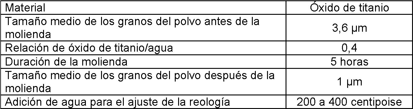
Se obtiene una capa separadora de microfiltración que tiene un umbral de corte de 1,4 |jm después de un depósito directo sobre el soporte de la siguiente manera.A microfiltration separating layer having a cutoff threshold of 1.4 µm is obtained after direct deposit on the support in the following manner.
Se hace penetrar, por bombeo, la suspensión en los canales para ponerla en contacto con la superficie de los canales. El mecanismo impulsor del depósito es la atracción del líquido de la suspensión por la porosidad del soporte poroso.The suspension is pumped into the channels to bring it into contact with the surface of the channels. The driving mechanism of the reservoir is the attraction of the suspension liquid by the porosity of the porous support.
El espesor del depósito de partículas de óxido de titanio en la superficie y por lo tanto la masa depositada por unidad de superficie depende del tiempo de residencia de la suspensión en los canales del soporte.The thickness of the deposit of titanium oxide particles on the surface and therefore the mass deposited per unit area depends on the residence time of the suspension in the channels of the support.
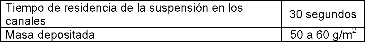
La operación se repite dos veces para una masa depositada final de 110 g/m2 aproximadamente.The operation is repeated twice for a final deposited mass of approximately 110 g / m2.
Ciclo de cocción para una sinterización de la capaFiring cycle for layer sintering

La fabricación de elementos de separación por flujo tangencial de microfiltración con umbrales de cortes inferiores a 1,4 jm y de elementos de separación, por flujo tangencial de ultrafiltración y de nanofiltración se obtendrán por depósitos sucesivos sobre tal primera capa a partir de suspensiones más finas con ciclos térmicos adaptados.The manufacture of separation elements by tangential flow of microfiltration with cut thresholds lower than 1.4 jm and of separation elements, by tangential flow of ultrafiltration and nanofiltration will be obtained by successive deposits on said first layer from finer suspensions with adapted thermal cycles.
La invención no se limita a los ejemplos descritos y representados, ya que se pueden aportar a ella diversas modificaciones sin salirse de su marco. The invention is not limited to the examples described and represented, since various modifications can be made to it without departing from its scope.
Claims (16)
Applications Claiming Priority (2)
| Application Number | Priority Date | Filing Date | Title |
|---|---|---|---|
| FR1457744A FR3024664B1 (en) | 2014-08-11 | 2014-08-11 | NOVEL GEOMETRIES OF TANGENTIAL FLOW SEPARATION MULTI-CHANNEL TUBULAR ELEMENTS INCLUDING TURBULENCE PROMOTERS AND MANUFACTURING METHOD |
| PCT/FR2015/051998 WO2016024056A1 (en) | 2014-08-11 | 2015-07-21 | Novel geometries of multichannel tubular elements intended for separation via tangential flow and having built-in turbulence promoters, and manufacturing method |
Publications (1)
| Publication Number | Publication Date |
|---|---|
| ES2860927T3 true ES2860927T3 (en) | 2021-10-05 |
Family
ID=51862459
Family Applications (1)
| Application Number | Title | Priority Date | Filing Date |
|---|---|---|---|
| ES15753393T Active ES2860927T3 (en) | 2014-08-11 | 2015-07-21 | New geometries of tangential flow separation multichannel tubular elements that integrate turbulence promoters and manufacturing process |
Country Status (12)
| Country | Link |
|---|---|
| US (1) | US12053744B2 (en) |
| EP (1) | EP3180109B1 (en) |
| JP (1) | JP6815989B2 (en) |
| CN (1) | CN107155312B (en) |
| DK (1) | DK3180109T3 (en) |
| ES (1) | ES2860927T3 (en) |
| FR (1) | FR3024664B1 (en) |
| HU (1) | HUE054244T2 (en) |
| PL (1) | PL3180109T3 (en) |
| PT (1) | PT3180109T (en) |
| RU (1) | RU2692723C2 (en) |
| WO (1) | WO2016024056A1 (en) |
Families Citing this family (13)
| Publication number | Priority date | Publication date | Assignee | Title |
|---|---|---|---|---|
| FR3024665B1 (en) * | 2014-08-11 | 2020-05-08 | Technologies Avancees Et Membranes Industrielles | TANGENTIAL FLOW SEPARATION ELEMENT INCLUDING TRAFFIC OBSTACLES AND MANUFACTURING METHOD |
| FR3024663B1 (en) * | 2014-08-11 | 2020-05-08 | Technologies Avancees Et Membranes Industrielles | NOVEL GEOMETRIES OF TANGULAR FLOW SEPARATION SINGLE-CHANNEL TUBULAR ELEMENTS INCLUDING TURBULENCE PROMOTERS AND MANUFACTURING METHOD |
| US10089416B1 (en) * | 2015-03-12 | 2018-10-02 | Stratasys, Inc. | Self-supporting internal passageways for powder metal additive manufacturing |
| FR3060410B1 (en) | 2016-12-21 | 2019-05-24 | Technologies Avancees Et Membranes Industrielles | TANGENTIAL FLOW SEPARATION ELEMENT INTEGRATING FLEXIBLE CHANNELS |
| WO2018235210A1 (en) * | 2017-06-21 | 2018-12-27 | エム・テクニック株式会社 | Filtration membrane module and filtration method |
| DE102018003063A1 (en) * | 2018-04-14 | 2019-10-17 | Linde Aktiengesellschaft | Method for the generative production of a three-dimensional membrane-like component, and such a three-dimensional membran component |
| FR3088832B1 (en) * | 2018-11-27 | 2022-01-14 | Tech Avancees Et Membranes Industrielles | Process for the manufacture by addition of material of inorganic filtration supports and membrane obtained |
| FR3088831B1 (en) * | 2018-11-27 | 2020-12-04 | Tech Avancees Et Membranes Industrielles | Manufacturing process by adding material from inorganic filtration media from a hot-melt filament and membrane obtained |
| DE102020121547A1 (en) * | 2020-08-17 | 2022-02-17 | InnoSpire Technologies GmbH | Monolithic ceramic membrane filters |
| DE102020121549A1 (en) * | 2020-08-17 | 2022-02-17 | InnoSpire Technologies GmbH | Monolithic membrane filter |
| US20230321607A1 (en) * | 2020-08-17 | 2023-10-12 | InnoSpire Technologies GmbH | Monolithic Membrane Filters |
| FR3116446B1 (en) * | 2020-11-23 | 2022-11-25 | Tech Avancees Et Membranes Industrielles | Separation element of a liquid medium with high parietal shear stress |
| CN112676575B (en) * | 2020-12-16 | 2023-05-05 | 南京晨光集团有限责任公司 | Selective laser melting forming method for large-diameter pipeline |
Family Cites Families (23)
| Publication number | Priority date | Publication date | Assignee | Title |
|---|---|---|---|---|
| FR2503616A1 (en) * | 1978-11-27 | 1982-10-15 | Commissariat Energie Atomique | Ceramic tubes with irregular flow cross=section - produced by indentation of extruded tube |
| FR2503615B1 (en) * | 1978-11-27 | 1985-10-11 | Commissariat Energie Atomique | METHOD FOR MANUFACTURING CERAMIC CYLINDRICAL TUBES HAVING LOCALIZED FOOTPRINTS AND DEVICE FOR CARRYING OUT SAID METHOD |
| JPS6220601U (en) * | 1985-07-23 | 1987-02-07 | ||
| GB2223690B (en) * | 1988-10-17 | 1991-05-01 | Roger Stanley White | Filtration systems |
| DE4134223C1 (en) * | 1991-10-16 | 1992-11-12 | Stora Feldmuehle Ag, 4000 Duesseldorf, De | |
| GB9504908D0 (en) * | 1995-03-10 | 1995-04-26 | Bellhouse Brian John | Filter |
| FR2736843B1 (en) | 1995-07-19 | 1997-09-26 | Centre Nat Rech Scient | POROUS IMPRESSION TUBE FOR TANGENTIAL FILTRATION |
| FR2741821B1 (en) * | 1995-12-05 | 1998-02-20 | Tami Ind | INORGANIC FILTRATION TUBULAR ELEMENT HAVING INCREASED FILTRATION SURFACE AND MECHANICAL STRENGTH |
| US5785851A (en) * | 1996-08-23 | 1998-07-28 | Vesuvius Crucible Company | High capacity filter |
| CN100393399C (en) * | 2001-09-17 | 2008-06-11 | 日本碍子株式会社 | DDR type zeolite membrane, and composite ddr type zeolite membrane, and method for preparation thereof |
| NZ531800A (en) * | 2001-09-17 | 2005-04-29 | Ngk Insulators Ltd | Method for preparing ddr type zeolite film, ddr type zeolite film, and composite ddr type zeolite film, and method for preparation thereof |
| US6805730B2 (en) * | 2002-01-29 | 2004-10-19 | Amersham Biosciences Membrane Separations Corp. | Convoluted surface hollow fiber membranes |
| RU2287358C1 (en) * | 2005-06-08 | 2006-11-20 | Николай Яковлевич ЗАЙЦЕВ | Separating filter element for cleaning and drying gases |
| FR2914197B1 (en) * | 2007-03-26 | 2009-12-11 | Applexion | TANGENTIAL FILTRATION SUPPORT AND PROCESS FOR PREPARING THE SAME |
| US20110100900A1 (en) * | 2008-04-28 | 2011-05-05 | Kenneth Joseph Drury | Monolith Membrane Module for Liquid Filtration |
| US8563879B2 (en) * | 2009-04-10 | 2013-10-22 | Sierra Instruments | Inertial microbalance filter assembly |
| GB0906751D0 (en) * | 2009-04-18 | 2009-06-03 | Fairey Filtration Systems Ltd | Filter |
| GB201014950D0 (en) * | 2010-09-08 | 2010-10-20 | Johnson Matthey Plc | Catalyst manufacturing method |
| CN103702811B (en) * | 2011-06-01 | 2017-03-01 | 联邦材料研究与测试研究所 | A kind of method and device for manufacturing shaped-article |
| KR101320467B1 (en) * | 2011-10-26 | 2013-10-22 | 주식회사 부강테크 | Filtering Apparatus having Fixed-Type Chaos-Flow Inducer |
| ES2427715B1 (en) * | 2012-03-30 | 2014-05-09 | Asociación De Investigación De La Industria Del Juguete, Conexas Y Afines | Procedure for the manufacture of monolithic systems of a ceramic or carbonaceous nature |
| WO2014092969A1 (en) * | 2012-12-13 | 2014-06-19 | 3M Innovative Properties Company | Constructions for fluid membrane separation devices |
| WO2014093743A1 (en) * | 2012-12-13 | 2014-06-19 | 3M Innovative Properties Company | Constructions for fluid membrane separation devices |
-
2014
- 2014-08-11 FR FR1457744A patent/FR3024664B1/en active Active
-
2015
- 2015-07-21 RU RU2017107769A patent/RU2692723C2/en active
- 2015-07-21 EP EP15753393.6A patent/EP3180109B1/en active Active
- 2015-07-21 WO PCT/FR2015/051998 patent/WO2016024056A1/en active Application Filing
- 2015-07-21 PT PT157533936T patent/PT3180109T/en unknown
- 2015-07-21 US US15/502,547 patent/US12053744B2/en active Active
- 2015-07-21 PL PL15753393T patent/PL3180109T3/en unknown
- 2015-07-21 DK DK15753393.6T patent/DK3180109T3/en active
- 2015-07-21 JP JP2017507691A patent/JP6815989B2/en active Active
- 2015-07-21 CN CN201580043464.3A patent/CN107155312B/en active Active
- 2015-07-21 ES ES15753393T patent/ES2860927T3/en active Active
- 2015-07-21 HU HUE15753393A patent/HUE054244T2/en unknown
Also Published As
| Publication number | Publication date |
|---|---|
| US12053744B2 (en) | 2024-08-06 |
| JP2017532187A (en) | 2017-11-02 |
| RU2692723C2 (en) | 2019-06-26 |
| CN107155312B (en) | 2021-03-23 |
| EP3180109B1 (en) | 2021-02-24 |
| EP3180109A1 (en) | 2017-06-21 |
| FR3024664B1 (en) | 2020-05-08 |
| US20170232393A1 (en) | 2017-08-17 |
| CN107155312A (en) | 2017-09-12 |
| RU2017107769A3 (en) | 2019-02-04 |
| RU2017107769A (en) | 2018-09-13 |
| PL3180109T3 (en) | 2021-07-12 |
| JP6815989B2 (en) | 2021-01-20 |
| HUE054244T2 (en) | 2021-08-30 |
| WO2016024056A1 (en) | 2016-02-18 |
| PT3180109T (en) | 2021-04-20 |
| DK3180109T3 (en) | 2021-05-17 |
| FR3024664A1 (en) | 2016-02-12 |
Similar Documents
| Publication | Publication Date | Title |
|---|---|---|
| ES2860927T3 (en) | New geometries of tangential flow separation multichannel tubular elements that integrate turbulence promoters and manufacturing process | |
| ES2885430T3 (en) | New geometries of single-channel tubular elements for tangential flow separation that integrate turbulence promoters and a manufacturing process | |
| ES2865110T3 (en) | Separation element through tangential flow that integrates obstacles to circulation and manufacturing procedure | |
| ES2883239T3 (en) | Procedure for manufacturing filtration membranes using additive technique and membranes obtained | |
| ES2844939T3 (en) | Tangential flow separation element that integrates flexural channels | |
| BR112019010923B1 (en) | TANGENTIAL FLOW SEPARATION ELEMENT INTEGRATING FLOW CHANNELS |