ES2829581T3 - Procedure and apparatus for providing quality of service (QOS) flow in a wireless communication system - Google Patents
Procedure and apparatus for providing quality of service (QOS) flow in a wireless communication system Download PDFInfo
- Publication number
- ES2829581T3 ES2829581T3 ES18185097T ES18185097T ES2829581T3 ES 2829581 T3 ES2829581 T3 ES 2829581T3 ES 18185097 T ES18185097 T ES 18185097T ES 18185097 T ES18185097 T ES 18185097T ES 2829581 T3 ES2829581 T3 ES 2829581T3
- Authority
- ES
- Spain
- Prior art keywords
- drb
- qos
- qfi
- sdap
- mapping
- Prior art date
- Legal status (The legal status is an assumption and is not a legal conclusion. Google has not performed a legal analysis and makes no representation as to the accuracy of the status listed.)
- Active
Links
- 238000000034 method Methods 0.000 title claims abstract description 36
- 238000004891 communication Methods 0.000 title description 31
- 230000006978 adaptation Effects 0.000 claims abstract description 8
- 102100022734 Acyl carrier protein, mitochondrial Human genes 0.000 claims abstract 7
- 101000678845 Homo sapiens Acyl carrier protein, mitochondrial Proteins 0.000 claims abstract 7
- 238000013507 mapping Methods 0.000 description 159
- 230000011664 signaling Effects 0.000 description 25
- 101150014328 RAN2 gene Proteins 0.000 description 14
- 230000008859 change Effects 0.000 description 14
- 238000010586 diagram Methods 0.000 description 7
- 230000006870 function Effects 0.000 description 7
- 238000012545 processing Methods 0.000 description 7
- 238000012546 transfer Methods 0.000 description 6
- 238000005538 encapsulation Methods 0.000 description 5
- 230000008569 process Effects 0.000 description 5
- 230000002441 reversible effect Effects 0.000 description 5
- 230000005540 biological transmission Effects 0.000 description 4
- 238000013461 design Methods 0.000 description 4
- 230000009471 action Effects 0.000 description 3
- 238000013459 approach Methods 0.000 description 3
- 239000000872 buffer Substances 0.000 description 3
- 230000001143 conditioned effect Effects 0.000 description 3
- 230000004069 differentiation Effects 0.000 description 3
- 230000001360 synchronised effect Effects 0.000 description 3
- 230000004913 activation Effects 0.000 description 2
- 238000004458 analytical method Methods 0.000 description 2
- 238000004590 computer program Methods 0.000 description 2
- 238000005516 engineering process Methods 0.000 description 2
- 230000003993 interaction Effects 0.000 description 2
- 230000007774 longterm Effects 0.000 description 2
- 238000007726 management method Methods 0.000 description 2
- 239000011159 matrix material Substances 0.000 description 2
- 238000010295 mobile communication Methods 0.000 description 2
- 230000004048 modification Effects 0.000 description 2
- 238000012986 modification Methods 0.000 description 2
- 230000003287 optical effect Effects 0.000 description 2
- 239000002245 particle Substances 0.000 description 2
- 101150074586 RAN3 gene Proteins 0.000 description 1
- 230000008901 benefit Effects 0.000 description 1
- 230000002457 bidirectional effect Effects 0.000 description 1
- 230000000295 complement effect Effects 0.000 description 1
- 230000008878 coupling Effects 0.000 description 1
- 238000010168 coupling process Methods 0.000 description 1
- 238000005859 coupling reaction Methods 0.000 description 1
- 230000003111 delayed effect Effects 0.000 description 1
- 230000001419 dependent effect Effects 0.000 description 1
- 230000000977 initiatory effect Effects 0.000 description 1
- 230000003834 intracellular effect Effects 0.000 description 1
- 230000014759 maintenance of location Effects 0.000 description 1
- 230000007246 mechanism Effects 0.000 description 1
- 230000008520 organization Effects 0.000 description 1
- 239000005022 packaging material Substances 0.000 description 1
- 102000005962 receptors Human genes 0.000 description 1
- 108020003175 receptors Proteins 0.000 description 1
- 238000012958 reprocessing Methods 0.000 description 1
- 230000004044 response Effects 0.000 description 1
Classifications
-
- H—ELECTRICITY
- H04—ELECTRIC COMMUNICATION TECHNIQUE
- H04W—WIRELESS COMMUNICATION NETWORKS
- H04W76/00—Connection management
- H04W76/10—Connection setup
-
- H—ELECTRICITY
- H04—ELECTRIC COMMUNICATION TECHNIQUE
- H04W—WIRELESS COMMUNICATION NETWORKS
- H04W28/00—Network traffic management; Network resource management
- H04W28/02—Traffic management, e.g. flow control or congestion control
- H04W28/10—Flow control between communication endpoints
- H04W28/12—Flow control between communication endpoints using signalling between network elements
-
- H—ELECTRICITY
- H04—ELECTRIC COMMUNICATION TECHNIQUE
- H04L—TRANSMISSION OF DIGITAL INFORMATION, e.g. TELEGRAPHIC COMMUNICATION
- H04L41/00—Arrangements for maintenance, administration or management of data switching networks, e.g. of packet switching networks
- H04L41/50—Network service management, e.g. ensuring proper service fulfilment according to agreements
- H04L41/5003—Managing SLA; Interaction between SLA and QoS
- H04L41/5019—Ensuring fulfilment of SLA
-
- H—ELECTRICITY
- H04—ELECTRIC COMMUNICATION TECHNIQUE
- H04L—TRANSMISSION OF DIGITAL INFORMATION, e.g. TELEGRAPHIC COMMUNICATION
- H04L67/00—Network arrangements or protocols for supporting network services or applications
- H04L67/14—Session management
- H04L67/141—Setup of application sessions
-
- H—ELECTRICITY
- H04—ELECTRIC COMMUNICATION TECHNIQUE
- H04W—WIRELESS COMMUNICATION NETWORKS
- H04W28/00—Network traffic management; Network resource management
- H04W28/02—Traffic management, e.g. flow control or congestion control
- H04W28/0268—Traffic management, e.g. flow control or congestion control using specific QoS parameters for wireless networks, e.g. QoS class identifier [QCI] or guaranteed bit rate [GBR]
-
- H—ELECTRICITY
- H04—ELECTRIC COMMUNICATION TECHNIQUE
- H04W—WIRELESS COMMUNICATION NETWORKS
- H04W76/00—Connection management
-
- H—ELECTRICITY
- H04—ELECTRIC COMMUNICATION TECHNIQUE
- H04W—WIRELESS COMMUNICATION NETWORKS
- H04W76/00—Connection management
- H04W76/10—Connection setup
- H04W76/11—Allocation or use of connection identifiers
Landscapes
- Engineering & Computer Science (AREA)
- Computer Networks & Wireless Communication (AREA)
- Signal Processing (AREA)
- Mobile Radio Communication Systems (AREA)
Abstract
Un procedimiento de un nodo de red, que comprende: transmitir un primer mensaje con una configuración de portador de radio de datos, DRB, a un equipo de usuario, UE, para establecer un DRB predeterminado para una sesión de unidad de datos de protocolo, PDU, en el que la configuración del DRB incluye una configuración de ID de flujo QoS, QFI, usada indicar si un campo QFI está presente o no en el enlace ascendente para el DRB predeterminado y la configuración de QFI siempre se establece en un valor que indica que el campo QFI está presente en el enlace ascendente para el DRB predeterminado (1205); establecer el DRB predeterminado con la presencia del campo QFI en el enlace ascendente (1210); y recibir una PDU de protocolo de adaptación de datos de servicio, SDAP, con el campo QFI a través del DRB predeterminado del UE (1215).A method of a network node, comprising: transmitting a first message with a data radio bearer configuration, DRB, to a user equipment, UE, to establish a predetermined DRB for a protocol data unit session, PDU, in which the DRB setting includes a QoS flow ID setting, QFI, used to indicate whether or not a QFI field is present in the uplink for the default DRB and the QFI setting is always set to a value that indicates that the QFI field is present in the uplink for the default DRB (1205); setting the default DRB with the presence of the QFI field in the uplink (1210); and receiving a Service Data Adaptation Protocol PDU, SDAP, with the QFI field through the UE's default DRB (1215).
Description
DESCRIPCIÓNDESCRIPTION
Procedimiento y aparato para proporcionar el flujo de calidad de servicio (QOS) en un sistema de comunicación inalámbricaProcedure and apparatus for providing quality of service (QOS) flow in a wireless communication system
Esta divulgación generalmente hace referencia a las redes de comunicación inalámbrica, y más particularmente, a un procedimiento y aparato para proporcionar el flujo QOS en un sistema de comunicación inalámbrica.This disclosure generally refers to wireless communication networks, and more particularly, to a method and apparatus for providing QOS flow in a wireless communication system.
Con el aumento rápido de la demanda de la comunicación de grandes cantidades de datos a y desde dispositivos de comunicación móvil, las redes móviles tradicionales de comunicación de voz evolucionan a redes que se comunican con paquetes de datos de Protocolo de Internet (IP). Tal comunicación de paquetes de datos de IP puede proporcionar servicios de comunicación de voz sobre IP, multimedia, multidifusión y servicios de comunicación bajo demanda a los usuarios de dispositivos de comunicación móvil.With the rapidly increasing demand for communicating large amounts of data to and from mobile communication devices, traditional mobile voice communication networks are evolving into networks that communicate with Internet Protocol (IP) packets of data. Such IP packet data communication can provide voice over IP, multimedia, multicast, and on-demand communication services to users of mobile communication devices.
Una estructura de red ilustrativa es una Red de Acceso de Radio Terrestre Universal Evolucionada (E-UTRAN). El sistema E-UTRAN puede proporcionar un alto flujo de datos para realizar los servicios de voz sobre IP y multimedia mencionados anteriormente. Una nueva tecnología de radio para la próxima generación (por ejemplo, 5G) se discute actualmente por la organización de estándares 3GPP. En consecuencia, los cambios al cuerpo actual del estándar 3GPP se presentan y consideran actualmente para evolucionar y finalizar con el estándar 3GPP.An illustrative network structure is an Evolved Universal Terrestrial Radio Access Network (E-UTRAN). The E-UTRAN system can provide a high data flow to realize the above-mentioned voice over IP and multimedia services. A new radio technology for the next generation (eg 5G) is currently being discussed by the 3GPP standards organization. Accordingly, changes to the current body of the 3GPP standard are currently presented and considered to evolve and finalize with the 3GPP standard.
CONVIDA WIRELESS en el "Formato de encabezado SDAP", 3GPP DRAFT, R2-1707351, analiza el formato de encabezado del Protocolo de adaptación de datos de servicio (SDAP) para el propósito de QoS reflectante NAS o QoS reflectante AS.CONVIDA WIRELESS in "SDAP Header Format", 3GPP DRAFT, R2-1707351, parses the Service Data Adaptation Protocol (SDAP) header format for the purpose of NAS reflective QoS or AS reflective QoS.
SumarioSummary
Los métodos y aparatos se divulgan desde la perspectiva de un nodo de red y se definen en las reivindicaciones independientes adjuntas. Las reivindicaciones dependientes adjuntas definen las realizaciones preferentes de las mismas. En una realización, el procedimiento incluye que el nodo de red transmita un primer mensaje con una configuración de DRB (Portador de radio de datos) a un UE (Equipo de usuario) para establecer un DRB predeterminado para una sesión de PDU (Unidad de datos de protocolo), en el que la configuración DRB incluye una configuración q Fi (ID de flujo QoS) usada para indicar si un campo QFI está presente o no en el enlace ascendente para el DRB predeterminado y la configuración QFI siempre se establece en un valor que indica que el campo QFI está presente en el enlace ascendente para el DRB predeterminado. El procedimiento incluye además el nodo de red que establece el DRB predeterminado con una presencia del campo QFI en el enlace ascendente. El procedimiento también incluye el nodo de red que recibe una PDU del SDAP (Protocolo de adaptación de datos de servicio) con el campo QFI a través del DRB predeterminado del UE.The methods and apparatus are disclosed from the perspective of a network node and are defined in the accompanying independent claims. The attached dependent claims define the preferred embodiments thereof. In one embodiment, the method includes the network node transmitting a first message with a DRB (Data Radio Bearer) configuration to a UE (User Equipment) to establish a predetermined DRB for a PDU (Data Unit) session. protocol), wherein the DRB configuration includes a configuration q F i (FlowID QoS) used to indicate whether a QFI field is present or not in the uplink for the default and DRB the QFI configuration is always set to one A value indicating that the QFI field is present in the uplink for the default DRB. The procedure further includes the network node that sets the default DRB with a presence of the QFI field in the uplink. The method also includes the network node that receives an SDAP (Service Data Adaptation Protocol) PDU with the QFI field through the default DRB of the UE.
Breve descripción de los dibujosBrief description of the drawings
La Figura 1 muestra un diagrama de un sistema de comunicación inalámbrica de acuerdo con una realización ilustrativa.Figure 1 shows a diagram of a wireless communication system according to an illustrative embodiment.
La Figura 2 es un diagrama de bloques de un sistema transmisor (conocido además como red de acceso) y un sistema receptor (conocido además como equipo de usuario o UE) de acuerdo con una realización ilustrativa. La Figura 3 es un diagrama de bloques funcionales de un sistema de comunicación de acuerdo con una realización ilustrativa.Figure 2 is a block diagram of a transmitter system (further known as an access network) and a receiver system (further known as user equipment or UE) in accordance with an illustrative embodiment. Figure 3 is a functional block diagram of a communication system in accordance with an illustrative embodiment.
La Figura 4 es un diagrama de bloques funcionales del código del programa de la Figura 3 de acuerdo con una realización ilustrativa.Figure 4 is a functional block diagram of the program code of Figure 3 in accordance with an illustrative embodiment.
La Figura 5 es una reproducción de la Figura 12-1 del 3GPP TS 38.300 v0.4.1.Figure 5 is a reproduction of Figure 12-1 of the 3GPP TS 38.300 v0.4.1.
La Figura 6 es una reproducción de la Figura A.6-1 del 3GPP TS 38.300 v0.4.1.Figure 6 is a reproduction of Figure A.6-1 of 3GPP TS 38.300 v0.4.1.
La Figura 7 es una reproducción de la Figura 5.7.1-1 del TS 23.501 v1.0.0.Figure 7 is a reproduction of Figure 5.7.1-1 of TS 23.501 v1.0.0.
La Figura 8 es la reproducción de la Figura 1 de 3GPP R2-1707159.Figure 8 is the reproduction of Figure 1 of 3GPP R2-1707159.
La Figura 9 es la reproducción de la Figura 2 de 3GPP R2-1707159.Figure 9 is the reproduction of Figure 2 of 3GPP R2-1707159.
La Figura 10 es la reproducción de la Figura 3 de 3GPP R2-1707159.Figure 10 is the reproduction of Figure 3 of 3GPP R2-1707159.
La Figura 11 es la reproducción de la Figura 4 de 3GPP R2-1707159.Figure 11 is the reproduction of Figure 4 of 3GPP R2-1707159.
La Figura 12 es un diagrama de flujo de acuerdo con una realización ilustrativa.Figure 12 is a flow chart in accordance with an illustrative embodiment.
La Figura 13 es un diagrama de flujo de acuerdo con un ejemplo útil para comprender la invención.Figure 13 is a flow chart in accordance with an example useful for understanding the invention.
La Figura 14 es un diagrama de flujo de acuerdo con un ejemplo útil para comprender la invención.Figure 14 is a flow chart in accordance with an example useful for understanding the invention.
Descripción detalladaDetailed description
Los sistemas y dispositivos de comunicación inalámbrica ilustrativos descritos más abajo emplean un sistema de comunicación inalámbrica, que soporta un servicio de difusión. Los sistemas de comunicación inalámbrica se implementan ampliamente para proporcionar diversos tipos de comunicación tales como voz, datos, y semejantes. Estos sistemas pueden basarse en acceso múltiple por división de código (CDMA), acceso múltiple por división de tiempo (TDMA), acceso múltiple por división de frecuencia ortogonal (OFDMA), acceso inalámbrico 3GPP LTE (Evolución a largo plazo), 3GPP LTE-A o LTE-Advanced (Evolución a largo plazo avanzada), 3GPP2 UMB (Banda ancha ultra móvil), WiMax, o algunas otras técnicas de modulación.The illustrative wireless communication systems and devices described below employ a wireless communication system, which supports a broadcast service. Wireless communication systems are widely implemented to provide various types of communication such as voice, data, and the like. These systems can be based on code division multiple access (CDMA), time division multiple access (TDMA), orthogonal frequency division multiple access (OFDMA), 3GPP LTE wireless access (Long-term evolution), 3GPP LTE-A or LTE-Advanced (Advanced long-term evolution), 3GPP2 UMB (Ultra Mobile Broadband), WiMax, or some other modulation techniques.
En particular, los dispositivos de sistemas de comunicación inalámbrica ilustrativos que se describen a continuación pueden diseñarse para soportar uno o más estándares, como el estándar ofrecido por un consorcio llamado "Proyecto de Asociación de 3ra Generación" denominado en la presente memoria 3GPP, que incluye: TS 38.300 v0.4.1, "NR; NR y NG-RAN Overall Description; Stage 2"; TS 23.501 v1.0.0, "System Architecture for the 5G System; Stage 2"; R2-1707159, "SDAP Header Format", Ericsson; R2-1707160, "Reflective QoS and Presence of Flow-ID", Ericsson; R2-1707161, "QoS Flow Remapping Within the Same Cell and in Handover", Ericsson; S2-170065, "Discussion on Reflective QoS activation using C-plane and U-plane", Huawei y HiSilicon; Nota del presidente de la reunión 3GPP RAN2#98; 3GPP RAN2 NR Nota del presidente de la reunión Ad Hoc#2; TS 38.323 v0.0.5, "NR; Packet Data Convergence Protocol (PDCP) specification"; Discusión por correo electrónico 3GPP [NR-AH2#08] [NR UP] En ejecución anexo TS 37.324 "Draft 37324-010-v1.doc"; R2-1705780, "QoS flow ID in AS Reflective QoS", CMCC; R2-1704648, "Discussion on reflective QoS", ZTE; R2-1704649, "Discussion on the SDAP PDU format", ZTE; TS 23.401 v14.0.0, "General Packet Radio Service (GPRS) enhancements for Evolved Universal Terrestrial Radio Access Network (E-UTRAN) access".In particular, the illustrative wireless communication system devices described below may be designed to support one or more standards, such as the standard offered by a consortium called the "3rd Generation Partnership Project" referred to herein as 3GPP, which includes : TS 38.300 v0.4.1, "NR; NR and NG-RAN Overall Description; Stage 2"; TS 23.501 v1.0.0, "System Architecture for the 5G System; Stage 2"; R2-1707159, "SDAP Header Format", Ericsson; R2-1707160, "Reflective QoS and Presence of Flow-ID", Ericsson; R2-1707161, "QoS Flow Remapping Within the Same Cell and in Handover", Ericsson; S2-170065, "Discussion on Reflective QoS activation using C-plane and U-plane", Huawei and HiSilicon; 3GPP RAN2 Meeting Chair Note # 98; 3GPP RAN2 NR Note from the chair of the Ad Hoc meeting # 2; TS 38.323 v0.0.5, "NR; Packet Data Convergence Protocol (PDCP) specification"; Discussion by email 3GPP [NR-AH2 # 08] [NR UP] In execution annex TS 37.324 "Draft 37324-010-v1.doc"; R2-1705780, "QoS flow ID in AS Reflective QoS", CMCC; R2-1704648, "Discussion on reflective QoS", ZTE; R2-1704649, "Discussion on the SDAP PDU format", ZTE; TS 23.401 v14.0.0, "General Packet Radio Service (GPRS) enhancements for Evolved Universal Terrestrial Radio Access Network (E-UTRAN) access".
La Figura 1 muestra un sistema de comunicación inalámbrica de acceso múltiple. Una red de acceso 100 (AN) incluye grupos de antenas múltiples, uno que incluye 104 y 106, otro que incluye 108 y 110, y un adicional que incluye 112 y 114. En la Figura 1, sólo se muestran dos antenas para cada grupo de antenas, sin embargo, pueden usarse más o menos antenas para cada grupo de antenas. El terminal de acceso 116 (AT) está en comunicación con las antenas 112 y 114, donde las antenas 112 y 114 transmiten información al terminal de acceso 116 a través del enlace delantero 120 y reciben información desde el terminal de acceso 116 a través del enlace inverso 118. El terminal de acceso (AT) 122 está en comunicación con las antenas 106 y 108, donde las antenas 106 y 108 transmiten información al terminal de acceso (AT) 122 a través del enlace directo 126 y reciben información desde el terminal de acceso (AT) 122 a través del enlace inverso 124. En un sistema FDD, los enlaces de comunicación 118, 120, 124 y 126 pueden usar la frecuencia diferente para la comunicación. Por ejemplo, el enlace directo 120 puede usar una frecuencia diferente entonces a la usada por el enlace inverso 118.Figure 1 shows a multiple access wireless communication system. An access network 100 (AN) includes multiple antenna groups, one that includes 104 and 106, another that includes 108 and 110, and an additional that includes 112 and 114. In Figure 1, only two antennas are shown for each group. However, more or fewer antennas can be used for each group of antennas. Access terminal 116 (AT) is in communication with antennas 112 and 114, where antennas 112 and 114 transmit information to access terminal 116 through forward link 120 and receive information from access terminal 116 through link inverse 118. Access terminal (AT) 122 is in communication with antennas 106 and 108, where antennas 106 and 108 transmit information to access terminal (AT) 122 through forward link 126 and receive information from terminal of access (AT) 122 via reverse link 124. In an FDD system, communication links 118, 120, 124 and 126 may use the different frequency for communication. For example, forward link 120 may use a different frequency then that used by reverse link 118.
Cada grupo de antenas y/o el área en donde se diseñan para comunicarse se refiere a menudo como un sector de la red de acceso. Cada grupo de antenas se diseña para comunicarse con terminales de acceso en un sector de las áreas cubiertas por la red de acceso 100.Each group of antennas and / or the area where they are designed to communicate is often referred to as a sector of the access network. Each group of antennas is designed to communicate with access terminals in a sector of the areas covered by the access network 100.
En la comunicación a través de los enlaces directos 120 y 126, las antenas de transmisión de la red de acceso 100 pueden usar la formación de haz para mejorar la relación señal-ruido de los enlaces directos para los terminales de acceso 116 y 122 diferentes. Además, una red de acceso que usa la formación de haz para transmitir a terminales de acceso dispersados aleatoriamente a través de su cobertura provoca menos interferencia a los terminales de acceso en las celdas vecinas que una red de acceso que transmite a través de una sola antena a todos sus terminales de acceso.In communication over the forward links 120 and 126, the transmitting antennas of the access network 100 may use beamforming to improve the signal-to-noise ratio of the forward links for the different access terminals 116 and 122. Furthermore, an access network that uses beamforming to transmit to access terminals randomly dispersed throughout its coverage causes less interference to access terminals in neighboring cells than an access network that transmits through a single antenna. to all your access terminals.
Una red de acceso (AN) puede ser una estación fija o estación base usada para comunicarse con las terminales y también puede denominarse punto de acceso, un Nodo B, una estación base, una estación base mejorada, un Nodo B evolucionado (eNB), un Nodo B de próxima generación o alguna otra terminología. Un terminal de acceso (AT) puede denominarse además un equipo de usuario (UE), un dispositivo de comunicación inalámbrica, un terminal, un terminal de acceso o alguna otra terminología.An access network (AN) can be a fixed station or base station used to communicate with terminals and can also be called an access point, a Node B, a base station, an enhanced base station, an evolved Node B (eNB), a next generation Node B or some other terminology. An access terminal (AT) may further be called a user equipment (UE), a wireless communication device, a terminal, an access terminal, or some other terminology.
La Figura 2 es un diagrama de bloques simplificado de un sistema transmisor 210 (conocido además como la red de acceso) y un sistema receptor 250 (conocido además como terminal de acceso (AT) o equipo de usuario (UE)) en un sistema MIMO 200. En el sistema transmisor 210, los datos de tráfico para un número de hilos de datos se proporciona desde una fuente de datos 212 a un procesador de datos de transmisión (TX) 214.Figure 2 is a simplified block diagram of a transmitter system 210 (also known as the access network) and a receiver system 250 (also known as an access terminal (AT) or user equipment (UE)) in a MIMO system. 200. In transmitter system 210, traffic data for a number of data threads is provided from a data source 212 to a transmission data processor (TX) 214.
Preferentemente, cada hilo de datos se transmite a través de una antena de transmisión respectiva. El procesador de datos TX 214 formatea, codifica, e intercala los datos de tráfico para cada hilo de datos en base a un esquema de codificación particular seleccionado para ese hilo de datos para proporcionar los datos codificados.Preferably, each data thread is transmitted through a respective transmitting antenna. The TX data processor 214 formats, encodes, and interleaves the traffic data for each data thread based on a particular encoding scheme selected for that data thread to provide the encoded data.
Los datos codificados para cada hilo de datos pueden multiplexarse con el dato piloto mediante el uso de técnicas OFDM. El dato piloto es típicamente un patrón de datos conocido que se procesa de manera conocida y puede usarse en el sistema receptor para estimar la respuesta del canal. El piloto multiplexado y los datos codificados para cada hilo de datos se modulan (es decir, se asignan símbolos) en base a un esquema de modulación particular (por ejemplo, BPSK, QPSK, M-PSK o M-QAM) que se selecciona para ese hilo de datos para proporcionar símbolos de modulación. La velocidad de datos, codificación y modulación para cada hilo de datos puede determinarse mediante instrucciones realizadas por el procesador 230.The encoded data for each data thread can be multiplexed with the pilot data through the use of OFDM techniques. The pilot data is typically a known data pattern that is processed in a known manner and can be used in the receiving system to estimate the channel response. The multiplexed pilot and encoded data for each data thread are modulated (i.e. symbols assigned) based on a particular modulation scheme (e.g. BPSK, QPSK, M-PSK, or M-QAM) that is selected for that data thread to provide modulation symbols. The data rate, encoding, and modulation for each data thread can be determined by instructions performed by processor 230.
Los símbolos de modulación para todos los flujos de datos entonces se proporcionan a un procesador TX MIMO 220, que puede procesar además los símbolos de modulación (por ejemplo, para OFDM). El procesador TX MIMO 220 entonces proporciona Nt secuencias de símbolos de modulación para Nt transmisores (TMTR) 222a al 222t. En ciertas realizaciones, el procesador TX MIMO 220 aplica los pesos de la formación de haz a los símbolos de los hilos de datos y a la antena desde la que se transmite el símbolo.The modulation symbols for all data streams are then provided to a TX MIMO processor 220, which can further process the modulation symbols (eg, for OFDM). The TX MIMO processor 220 then provides N t modulation symbol sequences for N t transmitters (TMTR) 222a through 222t. On In certain embodiments, the TX MIMO processor 220 applies the beamforming weights to the symbols on the data wires and to the antenna from which the symbol is transmitted.
Cada transmisor 222 recibe y procesa una secuencia de símbolos respectiva para proporcionar una o más señales analógicas, y condiciona además (por ejemplo, amplifica, filtra, y convierte hacia arriba) las señales analógicas para proporcionar una señal modulada adecuada para la transmisión a través del canal MIMO. Las señales moduladas Nt desde los transmisores 222a al 222t entonces se transmiten desde las antenas Nt 224a a la 224t, respectivamente. En el sistema receptor 250, las señales moduladas transmitidas se reciben por las antenas Nr 252a a la 252r y la señal recibida desde cada antena 252 se proporciona a un receptor (RCVR) respectivo 254a al 254r. Cada receptor 254 condiciona (por ejemplo, filtra, amplifica y convierte hacia abajo) una señal recibida respectiva, digitaliza la señal condicionada para proporcionar muestras, y procesa además las muestras para proporcionar una secuencia de símbolos "recibida" correspondiente.Each transmitter 222 receives and processes a respective symbol sequence to provide one or more analog signals, and further conditions (e.g., amplifies, filters, and up-converts) the analog signals to provide a modulated signal suitable for transmission through the MIMO channel. Nt modulated signals from transmitters 222a through 222t are then transmitted the antennas N t from 224a to 224t, respectively. At receiver system 250, transmitted modulated signals are received by antennas 252a to N r 252r and the received signal from each antenna 252 is provided to a receiver (RCVR) 254a to the respective 254r. Each receiver 254 conditions (eg, filters, amplifies, and downconverts) a respective received signal, digitizes the conditioned signal to provide samples, and further processes the samples to provide a corresponding "received" symbol sequence.
Un procesador de datos RX 260 entonces recibe y procesa las secuencias de símbolos recibidas Nr desde los receptores Nr 254 en base a una técnica de procesamiento del receptor particular para proporcionar las secuencias de símbolos "detectadas" Nt. El procesador de datos RX 260 entonces demodula, desintercala, y decodifica cada hilo de símbolos detectado para recuperar el dato de tráfico para el hilo de datos. El procesamiento por el procesador de datos RX 260 es complementario al realizado por el procesador TX MIMO 220 y el procesador de datos TX 214 en el sistema transmisor 210.An RX data processor 260 then receives and processes the received symbol streams from N R receivers 254 N r based on a processing technique to provide the particular receptor sequences symbols "detected" N t. The RX data processor 260 then demodulates, deinterleaves, and decodes each detected symbol thread to recover the traffic data for the data thread. Processing by data processor RX 260 is complementary to that performed by TX MIMO processor 220 and data processor TX 214 in transmitter system 210.
Un procesador 270 determina periódicamente qué matriz de codificación previa usar (discutido más abajo). El procesador 270 formula un mensaje de enlace inverso comprendiendo una porción de índice de matriz y una porción de valor de intervalo.A processor 270 periodically determines which pre-encoding matrix to use (discussed below). Processor 270 formulates a reverse link message comprising an array index portion and a slot value portion.
El mensaje de enlace inverso puede comprender diversos tipos de información respecto al enlace de comunicación y/o el hilo de datos recibido. El mensaje de enlace inverso entonces se procesa por un procesador de datos TX 238, que recibe además el dato de tráfico para un número de hilos de datos desde una fuente de datos 236, modulados por un modulador 280, condicionados por los transmisores 254a al 254r, y transmitidos de vuelta al sistema transmisor 210.The reverse link message may comprise various types of information regarding the communication link and / or the received data thread. The reverse link message is then processed by a TX data processor 238, which further receives the traffic data for a number of data threads from a data source 236, modulated by a modulator 280, conditioned by transmitters 254a to 254r , and transmitted back to transmitter system 210.
En el sistema transmisor 210, las señales moduladas desde el sistema receptor 250 se reciben por las antenas 224, se condicionan por los receptores 222, se demodulan por un demodulador 240, y se procesan por un procesador de datos RX 242 para extraer el mensaje de enlace de reserva transmitido por el sistema receptor 250. El procesador 230 entonces determina qué matriz de codificación previa usar para determinar los pesos de la formación de haz entonces procesa el mensaje extraído.In transmitter system 210, modulated signals from receiver system 250 are received by antennas 224, conditioned by receivers 222, demodulated by demodulator 240, and processed by RX data processor 242 to extract the signal message. spare link transmitted by receiver system 250. Processor 230 then determines which precoding matrix to use to determine beamforming weights then processes the extracted message.
Al regresar a la Figura 3, esta figura muestra un diagrama de bloques funcionales simplificado alternativo de un dispositivo de comunicación. Como se muestra en la Figura 3, el dispositivo de comunicación 300 en un sistema de comunicación inalámbrica puede usarse para realizar los UE (o AT) 116 y 122 en la Figura 1 o la estación base (o AN) 100 en la Figura 1, y el sistema de comunicaciones inalámbricas es preferentemente el sistema LTE. El dispositivo de comunicación 300 puede incluir un dispositivo de entrada 302, un dispositivo de salida 304, un circuito de control 306, una unidad de procesamiento central (CPU) 308, una memoria 310, un código de programa 312, y un transceptor 314. El circuito de control 306 ejecuta el código de programa 312 en la memoria 310 a través de la CPU 308, que controla de esta manera un funcionamiento del dispositivo de comunicaciones 300. El dispositivo de comunicaciones 300 puede recibir señales introducidas por un usuario a través del dispositivo de entrada 302, tal como un teclado o teclado numérico, y puede emitir imágenes y sonidos a través del dispositivo de salida 304, tal como un monitor o altavoces. El transceptor 314 se usa para recibir y transmitir señales inalámbricas, que entrega señales recibidas al circuito de control 306, y que emite señales generadas por el circuito de control 306 de forma inalámbrica. El dispositivo de comunicación 300 en un sistema de comunicación inalámbrica puede usarse además para realizar la AN 100 en la Figura 1.Returning to Figure 3, this figure shows an alternative simplified functional block diagram of a communication device. As shown in Figure 3, communication device 300 in a wireless communication system can be used to realize UE (or AT) 116 and 122 in Figure 1 or base station (or AN) 100 in Figure 1, and the wireless communication system is preferably the LTE system. Communication device 300 may include an input device 302, an output device 304, a control circuit 306, a central processing unit (CPU) 308, a memory 310, a program code 312, and a transceiver 314. The control circuit 306 executes the program code 312 in the memory 310 through the CPU 308, which thus controls an operation of the communication device 300. The communication device 300 can receive signals entered by a user through the input device 302, such as a keyboard or keypad, and can output images and sounds through output device 304, such as a monitor or speakers. The transceiver 314 is used to receive and transmit wireless signals, which delivers received signals to the control circuit 306, and which transmits signals generated by the control circuit 306 wirelessly. Communication device 300 in a wireless communication system can further be used to perform AN 100 in Figure 1.
La Figura 4 es un diagrama de bloques simplificado del código de programa 312 mostrado en la Figura 3. El código de programa 312 incluye una capa de aplicación 400, una porción 402 de Capa 3 y una porción 404 de Capa 2, y está acoplada a una porción 406 de Capa 1. La porción de la Capa 3 402 realiza generalmente el control de recursos de radio. La porción de la Capa 2404 realiza generalmente el control de enlace. La porción de la Capa 1 406 realiza generalmente las conexiones físicas.Figure 4 is a simplified block diagram of program code 312 shown in Figure 3. Program code 312 includes an application layer 400, a Layer 3 portion 402, and a Layer 2 portion 404, and is coupled to a Layer 1 portion 406. Layer 3 portion 402 generally performs radio resource control. Layer 2404 portion generally performs link control. The Layer 1 portion 406 generally makes the physical connections.
La 3GPP TS38.300 describió la capa SDAP (Protocolo de adaptación de datos de servicio) y QoS de la siguiente manera:3GPP TS38.300 described the SDAP (Service Data Adaptation Protocol) and QoS layer as follows:
6.5 Subcapa SDAP6.5 SDAP sublayer
Los principales servicios y funciones de SDAP incluyen:The main services and functions of SDAP include:
- Mapeo entre un flujo QoS y un portador de radio de datos; - Mapping between a QoS flow and a data radio bearer;
- Marcado de ID de flujo QoS (QFI) en paquetes DL y UL.- QoS Flow ID (QFI) marking on DL and UL packets.
Se configura una única entidad de protocolo de SDAP para cada sesión de PDU individual, excepto para DC, donde se pueden configurar dos entidades (una para MCG y otra para SCG; véase la subcláusula 12).A single SDAP protocol entity is configured for each individual PDU session, except for DC, where two entities can be configured (one for MCG and one for SCG; see subclause 12).
12 QoS12 QoS
La arquitectura de QoS en NG-RAN se muestra en la Figura 13-1 y se describe a continuación:The QoS architecture in NG-RAN is shown in Figure 13-1 and described below:
- Para cada UE, 5GC establece una o más sesiones de PDU.- For each UE, 5GC establishes one or more PDU sessions.
- Para cada UE, la NG-RAN establece uno o más Portadores de Radio de Datos (DRB) por Sesión de PDU. El NG-NG-RAN mapea paquetes que pertenecen a diferentes sesiones de PDU a diferentes DRB. Por tanto, la NG-RAN establece al menos un DRB por defecto para cada sesión de PDU indicada por 5GC al establecer la sesión de PDU.- For each UE, the NG-RAN establishes one or more Radio Data Bearers (DRBs) per PDU Session. The NG-NG-RAN maps packets belonging to different PDU sessions to different DRBs. Therefore, the NG-RAN establishes at least one default DRB for each PDU session indicated by 5GC when establishing the PDU session.
- Los filtros de paquetes de nivel NAS en el UE y en el 5GC asocian los paquetes UL y DL con los flujos QoS. - El mapeo de nivel AS en el UE y en la NG-RAN asocia los flujos QoS UL y DL con DRB.- NAS level packet filters in UE and 5GC associate UL and DL packets with QoS flows. - AS level mapping in UE and NG-RAN associates UL and DL QoS flows with DRB.
[La Figura 12-1 de 3GPP TS 38.300 v0.4.1, titulada "Arquitectura QoS", se reproduce como Figura 5] El NG-RAN y el 5GC aseguran la calidad del servicio (por ejemplo, confiabilidad y retardo de destino) al mapear paquetes a los flujos QoS y DRB apropiados. Por lo tanto, existe un mapeo de 2 etapas de los flujos de IP a los flujos QoS (NAS) y de los flujos QoS a los DRB (Access Stratum).[Figure 12-1 of 3GPP TS 38.300 v0.4.1, titled "QoS Architecture", is reproduced as Figure 5] NG-RAN and 5GC ensure quality of service (eg, reliability and destination delay) when mapping packets to the appropriate QoS and DRB flows. Therefore, there is a 2-stage mapping of IP flows to QoS flows (NAS) and QoS flows to DRBs (Access Stratum).
En el NG-RAN, el portador de radio de datos (DRB) define el tratamiento del paquete en la interfaz de radio (Uu). Un DRB sirve paquetes con el mismo tratamiento de reenvío de paquetes. Se pueden establecer DRB separados para los flujos QoS que requieren un tratamiento de reenvío de paquetes diferente. En el enlace descendente, NG-RAN mapea los flujos QoS a los DRB en base al marcado NG-U (ID de flujo QoS) y los perfiles de QoS asociados. En el enlace ascendente, el UE marca los paquetes del enlace ascendente sobre Uu con el QFI con el fin de marcar los paquetes reenviados al CN.In the NG-RAN, the data radio bearer (DRB) defines the handling of the packet on the radio interface (Uu). A DRB serves packets with the same packet forwarding treatment. Separate DRBs can be established for QoS flows that require different packet forwarding treatment. On the downlink, NG-RAN maps QoS flows to DRBs based on NG-U marking (QoS flow ID) and associated QoS profiles. In the uplink, the UE marks the uplink packets over Uu with the QFI in order to mark the packets forwarded to the CN.
En el enlace ascendente, NG-RAN puede controlar el mapeo de los flujos QoS al DRB de dos formas diferentes: - Mapeo reflectante: para cada DRB, el UE supervisa los QFI de los paquetes de enlace descendente y aplica el mismo mapeo en el enlace ascendente; es decir, para un DRB, el UE mapea los paquetes de enlace ascendente que pertenecen a los flujos QoS correspondientes a los QFI y la sesión de PDU observadas en los paquetes de enlace descendente para ese DRB. Para habilitar este mapeo reflectante, NG-RAN marca los paquetes de enlace descendente sobre Uu con QFI.On the uplink, NG-RAN can control the mapping of QoS flows to the DRB in two different ways: - Reflective mapping: for each DRB, the UE monitors the QFIs of the downlink packets and applies the same mapping on the link upward; that is, for a DRB, the UE maps the uplink packets belonging to the QoS flows corresponding to the QFIs and PDU session observed in the downlink packets for that DRB. To enable this reflective mapping, NG-RAN marks downlink packets over Uu with QFI.
Es FFS si el marcado con un QFI se puede configurar de forma semiestática (para no incluir el ID de flujo QOS cuando no sea necesario). It is FFS if marking with a QFI can be configured semi-statically ( not to include the QOS flow ID when not required).
- Configuración explícita: además del mapeo reflectante, la NG-RAN puede configurar por RRC un enlace ascendente "Mapeo de flujo QoS a DRB". - Explicit configuration: in addition to reflective mapping, the NG-RAN can configure per RRC an uplink "QoS flow mapping to DRB".
La precedencia del mapeo configurado de RRC y la QoS reflectante es FFS (¿se puede actualizar la QoS reflectante y así anular un mapeo configurado de RRC? ¿O un ID de flujo QoS configurado al mapeo de DRB siempre tiene prioridad sobre un mapeo reflectante?) The precedence of RRC configured mapping and reflective QoS is FFS ( can reflective QoS be updated and thus override a configured RRC mapping? Or does a QoS flow ID configured to DRB mapping always take precedence over reflective mapping? )
Si un paquete UL entrante no coincide ni con un RRC configurado ni con un "ID de flujo QoS al mapeo de DRB" reflectante, el UE mapeará ese paquete con el DRB por defecto de la sesión de PDU.If an incoming UL packet matches neither a configured RRC nor a reflective "QoS flow ID to DRB mapping", the UE will map that packet to the default DRB of the PDU session.
Dentro de cada sesión de PDU, depende de NG-RAN cómo mapear múltiples flujos QoS a un DRB. El NG-RAN puede mapear un flujo GBR y un flujo que no es GBR, o más de un flujo GBR al mismo DRB, pero los mecanismos para optimizar estos casos no están dentro del ámbito de la estandarización. El momento de establecer los DRB no predeterminados entre NG-RAN y UE para el flujo QoS configurado durante el establecimiento de una sesión de PDU puede ser diferente del momento en que se establece la sesión de PDU. Depende de NG-RAN cuando se establecen DRB no predeterminados.Within each PDU session, it is up to NG-RAN how to map multiple QoS flows to a DRB. The NG-RAN can map a GBR stream and a non-GBR stream, or more than one GBR stream to the same DRB, but the mechanisms to optimize these cases are not within the scope of standardization. The time to set the non-default DRBs between NG-RAN and UE for the QoS flow configured during the establishment of a PDU session may be different from the time when the PDU session is established. Depends on NG-RAN when non-default DRBs are set.
En DC, los flujos QoS que pertenecen a la misma sesión de PDU pueden mapeados con diferentes tipos de portadores (ver subcláusula 4.5.2) y, como resultado, puede haber dos entidades SDAP diferentes configuradas para la misma sesión de PDU: una para MCG y otra para SCG (por ejemplo, cuando un portador MCG y un portador SCG se usan para dos flujos QoS diferentes).In DC, QoS flows that belong to the same PDU session can be mapped to different types of bearers (see subclause 4.5.2) and as a result, there can be two different SDAP entities configured for the same PDU session: one for MCG and another for SCG (for example, when a MCG bearer and an SCG bearer are used for two different QoS flows).
El soporte para la sesión de PDU mapeada a diferentes portadores está pendiente de conclusiones en SA2 y RAN3. Support for PDU session mapped to different bearers is pending in SA2 and RAN3.
Anexo A (informativo):Annex A (informative):
Manejo de QoS en RANQoS management in RAN
Cuándo y si incluir el QFI en su totalidad o en forma abreviada y el RQI en SDAP es FFS.When and if to include the QFI in full or in abbreviated form and the RQI in SDAP is FFS.
Todos los nombres y parámetros de los mensajes son FFS.All message names and parameters are FFS.
Estos reflejan el estado actual y es posible que deban actualizarse en base a otras decisiones.These reflect the current state and may need to be updated based on other decisions.
A.6 Flujo QoS UL iniciado por UEA.6 UE initiated UL QoS flow
La siguiente Figura muestra un ejemplo de flujo de mensajes cuando el UE AS recibe un paquete UL para un nuevo flujo QoS para el que no existe un QFI para el DRB.The following Figure shows an example message flow when the UE AS receives a UL packet for a new QoS flow for which there is no QFI for the DRB.
[Figura A.6-1 de 3GPP TS 38.300 v0.4.1, titulada "Paquete UL con un nuevo flujo QoS para el que no existe un mapeo en UE", se reproduce como la Figura 6][Figure A.6-1 of 3GPP TS 38.300 v0.4.1, titled "UL packet with a new QoS flow for which there is no mapping in UE", is reproduced as Figure 6]
0. La sesión de PDU y los DRB (incluido un DRB predeterminado) ya se han establecido.0. The PDU session and DRBs (including a default DRB) have already been established.
1. El UE AS recibe un paquete con un nuevo QFI de UE NAS.1. The UE AS receives a packet with a new QFI from UE NAS.
2. El UE usa el QFI del paquete para mapearlo a un DRB. Si no hay un mapeo del QFI a un DRB en la tabla de mapeo AS para esta sesión de PDU, entonces el paquete se asigna al DRB predeterminado.2. The UE uses the QFI of the packet to map it to a DRB. If there is no mapping from the QFI to a DRB in the AS mapping table for this PDU session, then the packet is assigned to the default DRB.
3. El UE envía el paquete en el DRB predeterminado. El UE incluye el q Fi en el encabezado SDAP si se ha configurado SDAP para este DRB.3. The UE sends the packet on the default DRB. The UE includes the q Fi in the SDAP header if SDAP has been configured for this DRB.
4. gNB envía paquetes UL por NG-U e incluye el QFI correspondiente.4. gNB sends UL packets over NG-U and includes the corresponding QFI.
5. Si gNB desea usar un nuevo DRB para este flujo QoS, configura un DRB. También puede optar por mover el flujo QoS a un DRB existente mediante el uso de la señalización RRC o los procedimientos de mapeo reflectante AS descritos anteriormente. Los detalles de esto se muestran en la Figura X.2-1 y la Figura X.3-1.5. If gNB wants to use a new DRB for this QoS flow, configure a DRB. You can also choose to move the QoS flow to an existing DRB by using RRC signaling or AS reflective mapping procedures described above. Details of this are shown in Figure X.2-1 and Figure X.3-1.
6. Los paquetes UL recibidos en UE AS con QFI se envían a través del DRB decidido por la tabla de mapeo de QFI a DRB. Si se configura en la etapa 5, los paquetes de datos de UL incluyen una marca de QoS (igual o correspondiente a QFI) en el encabezado SDAP.6. UL packets received in UE AS with QFI are sent through DRB decided by QFI to DRB mapping table. If configured in stage 5, UL data packets include a QoS mark (equal to or corresponding to QFI) in the SDAP header.
La 3GPP TS 23.501 modelo de QoS especificado para NR (New RAT/Radio) de la siguiente manera:The 3GPP TS 23.501 QoS model specified for NR (New RAT / Radio) as follows:
5.7 modelo QoS5.7 QoS model
5.7.1 Descripción general5.7.1 Overview
El modelo QoS 5G admite un marco basado en flujo QoS. El modelo QoS 5G admite tanto los flujos QoS que requieren una tasa de flujo de bits garantizada como los flujos QoS que no requieren una tasa de flujo de bits garantizada. El modelo QoS 5G también admite QoS reflectante (consulte la cláusula 5.7.5).The 5G QoS model supports a QoS flow-based framework. The 5G QoS model supports both QoS streams that require a guaranteed bit stream and QoS streams that do not require a guaranteed bit stream. The 5G QoS model also supports reflective QoS (see clause 5.7.5).
El flujo QoS es la mejor granularidad de diferenciación de QoS en la sesión de PDU. Un ID de flujo QoS (QFI) se usa para identificar un flujo QoS en el sistema 5G. El tráfico del plano de usuario con el mismo QFI dentro de una sesión de PDU recibe el mismo tratamiento de reenvío de tráfico (por ejemplo, programación, umbral de admisión). El QFI se transporta en un encabezado de encapsulación en N3 (y N9), es decir, sin ningún cambio en el encabezado del paquete e2e. Puede aplicarse a los PDU con diferentes tipos de carga útil, es decir, paquetes IP, PDU no estructuradas y tramas Ethernet. El QFI será único dentro de una sesión de PDU.The QoS flow is the best QoS differentiation granularity in the PDU session. A QoS flow ID (QFI) is used to identify a QoS flow in the 5G system. User plane traffic with the same QFI within a PDU session receives the same traffic forwarding treatment (eg, scheduling, admission threshold). The QFI is carried in an encapsulation header on N3 (and N9), that is, without any change in the header of the e2e packet. It can be applied to PDUs with different types of payload, that is, IP packets, unstructured PDUs, and Ethernet frames. The QFI will be unique within a PDU session.
NOTA 1: La vigilancia del tráfico del plano de usuario (por ejemplo, la imposición de MFBR) no se considera una diferenciación de QoS y la realizan las UPF en un nivel de granularidad SDF.NOTE 1: User plane traffic policing (eg MFBR enforcement) is not considered a QoS differentiation and is performed by UPFs at an SDF granularity level.
Cada flujo QoS (GBR y no GBR) está asociado con los siguientes parámetros de QoS (los detalles de los parámetros se describen en la cláusula 5.7.2):Each QoS flow (GBR and non-GBR) is associated with the following QoS parameters (details of the parameters are described in clause 5.7.2):
- Indicador de QoS 5G (5QI).- 5G QoS Indicator (5QI).
- Prioridad de asignación y retención (ARP).- Allocation and retention priority (ARP).
Cada flujo QoS de GBR está asociado además con los siguientes parámetros de QoS (los detalles se describen en la cláusula 5.7.2):Each GBR QoS flow is further associated with the following QoS parameters (details are described in clause 5.7.2):
- Tasa de bits de flujo garantizada (GFBR): UL y DL; - Guaranteed Stream Bit Rate (GFBR): UL and DL;
- Tasa máxima de bits de flujo (MFBR): UL y DL;- Maximum Stream Bit Rate (MFBR): UL and DL;
- Control de notificaciones.- Control of notifications.
Cada flujo QoS no GBR puede además estar asociado con el siguiente parámetro de QoS (los detalles se describen en la cláusula 5.7.2):Each non-GBR QoS flow can also be associated with the following QoS parameter (details are described in clause 5.7.2):
- Atributo de QoS reflectante (RQA).- Reflective QoS attribute (RQA).
Se admiten dos formas de controlar los flujos QoS:Two ways to control QoS flows are supported:
1) Para los flujos QoS no GBR con 5QI estandarizados, el valor de 5QI se usa como QFI como se define en la cláusula 5.7.4 y se usa un ARP predeterminado. En este caso, no se requiere señalización N2 adicional en el momento en que comienza el tráfico para los flujos QoS correspondientes; o1) For non-GBR QoS flows with standardized 5QI, the value of 5QI is used as QFI as defined in clause 5.7.4 and a default ARP is used. In this case, no additional N2 signaling is required at the time the traffic starts for the corresponding QoS flows; or
2) Para los flujos QoS GBR y no GBR, todos los parámetros de QoS necesarios correspondientes a una QFI se envían como perfil de QoS a (R)AN, UPF en el establecimiento de sesión de PDU o en el establecimiento/modificación del flujo QoS.2) For GBR and non-GBR QoS flows, all required QoS parameters corresponding to a QFI are sent as QoS profile to (R) AN, UPF at PDU session establishment or QoS flow establishment / modification .
Nota del editor: Ya sea más allá de los 5QI estandarizados, también los valores de 5QI pre configurados pueden usarse más como valores de QFI es FFS.Editor's Note: Be it beyond the standardized 5QI, also the pre-configured 5QI values can be used more like QFI values is FFS.
Los parámetros de QoS de un flujo QoS se proporcionan al (R)AN como un perfil de QoS sobre N2 en la sesión de PDU o en el establecimiento del flujo QoS y cuando se usa NG-RAN cada vez que se activa el plano de usuario. Los parámetros de QoS también se pueden preconfigurar en el (R)AN para flujos QoS que no son GBR (es decir, sin necesidad de señalizarlos a través de N2).The QoS parameters of a QoS flow are provided to the (R) AN as a QoS profile over N2 in the PDU session or QoS flow establishment and when NG-RAN is used every time the user plane is activated . QoS parameters can also be preconfigured in the (R) AN for QoS flows that are not GBR (ie without the need to signal them over N2).
El UE realiza la clasificación y marcado del tráfico del plano de usuario de UL, es decir, la asociación del tráfico de enlace ascendente a los flujos QoS, en base a las reglas de QoS. Estas reglas pueden ser señalizadas explícitamente a través de N1 (en el establecimiento de sesión de PDU o establecimiento de flujo QoS), pre configuradas en el UE o derivadas implícitamente por UE de QoS reflectante. Una regla de QoS contiene un identificador de regla de QoS, el QFI del flujo QoS, uno o más filtros de paquetes y un valor de precedencia. Puede haber más de una regla de QoS asociada con el mismo QFI (es decir, con el mismo flujo QoS).The UE performs UL user plane traffic classification and marking, that is, the association of uplink traffic to QoS flows, based on QoS rules. These rules can be explicitly signaled via N1 (at PDU session establishment or QoS flow establishment), pre-configured in the UE, or implicitly derived by UE from reflective QoS. A QoS rule contains a QoS rule identifier, the QFI of the QoS flow, one or more packet filters, and a precedence value. There can be more than one QoS rule associated with the same QFI (that is, with the same QoS flow).
Se requiere una regla de QoS predeterminada para cada sesión de PDU. La regla de QoS predeterminada es la única regla de QoS de una sesión de PDU que puede no contener ningún filtro de paquetes (en este caso, se debe usar el valor de precedencia más alto (es decir, la prioridad más baja)). Si la regla de QoS predeterminada no contiene un filtro de paquetes, la regla de QoS predeterminada define el tratamiento de los paquetes que no coinciden con ninguna otra regla de QoS en una sesión de PDU.A default QoS rule is required for each PDU session. The default QoS rule is the only QoS rule in a PDU session that may not contain any packet filters (in this case, the highest precedence value (that is, the lowest priority) should be used). If the default QoS rule does not contain a packet filter, the default QoS rule defines the handling of packets that do not match any other QoS rule in a PDU session.
Nota del editor: Es FFS si existe, además, la necesidad de que se proporcionen al UE reglas de QoS autorizadas previamente.Editor's note: It is FFS if there is also a need for pre-authorized QoS rules to be provided to the UE.
El SMF asigna el QFI para cada flujo QoS y deriva sus parámetros de QoS de la información proporcionada por el PCF. Cuando es aplicable, la SMF proporciona el QFI junto con el perfil de QoS que contiene los parámetros de QoS de un flujo QoS al (R)AN. La SMF proporciona la plantilla SDF (es decir, el conjunto de filtros de paquetes asociados con la SDF recibida de la PCF) junto con la precedencia SDF y la QFI correspondiente a la UPF que permite la clasificación y el marcado del tráfico del plano de usuario. Cuando corresponda, el SMF genera la(s) regla(s) de QoS para la sesión de PDU asignando identificadores de regla de QoS, agregando el QFI del flujo QoS, configurando los filtros de paquetes en la parte UL de la plantilla SDF y configurando la regla de QoS precedencia a la precedencia SDF. A continuación, las reglas de QoS se proporcionan al UE, lo que permite la clasificación y el marcado del tráfico del plano de usuario de UL.The SMF assigns the QFI for each QoS flow and derives its QoS parameters from the information provided by the PCF. When applicable, the SMF provides the QFI along with the QoS profile containing the QoS parameters of a QoS flow to the (R) AN. The SMF provides the SDF template (that is, the set of packet filters associated with the SDF received from the PCF) along with the SDF precedence and the corresponding QFI to the UPF that enables classification and marking of user plane traffic. . Where applicable, the SMF generates the QoS rule (s) for the PDU session by assigning QoS rule identifiers, adding the QFI of the QoS flow, configuring the packet filters in the UL part of the SDF template, and configuring the QoS rule precedence over SDF precedence. The QoS rules are then provided to the UE, enabling the classification and marking of UL user plane traffic.
Nota del editor: Algunas aplicaciones, por ejemplo, IMS, requieren también la parte DL de la plantilla SDF en la regla de QoS. Si el DL de la plantilla SDF debe enviarse para cada regla de QoS es FFS.Editor's note: Some applications, for example IMS, also require the DL part of the SDF template in the QoS rule. If the DL of the SDF template should be sent for each QoS rule it is FFS.
En la Figura 5.7.1-1 se ilustra el principio de clasificación y marcado del tráfico del plano de usuario y la correspondencia de los flujos QoS con los recursos de AN.Figure 5.7.1-1 illustrates the principle of classification and marking of user plane traffic and the mapping of QoS flows to AN resources.
[La Figura 5.7.1-1 de TS 23.501 v1.0.0, titulada "El principio de clasificación y marcado del plano de usuario para flujos QoS y mapeo a recursos AN", se reproduce en la Figura 7][Figure 5.7.1-1 of TS 23.501 v1.0.0, entitled "The principle of user plane classification and marking for QoS flows and mapping to AN resources", is reproduced in Figure 7]
En los paquetes de datos entrantes de DL, se clasifican en base a plantillas SDF de acuerdo con su precedencia SDF (sin iniciar señalización N4 adicional). La CN transmite la clasificación del tráfico del plano de usuario que pertenece a un flujo QoS a través de una marca de plano de usuario N3 (y N9) mediante el uso de un QFI. La AN vincula los flujos QoS a los recursos de la AN (es decir, portadores de radio de datos en el caso de 3GPP RAN). No existe una relación estricta de 1:1 entre los flujos QoS y los recursos de AN. Depende de la AN establecer los recursos de AN necesarios para hacer corresponder los flujos QoS con los DRB de modo que el UE reciba la QFI (y se pueda aplicar los QoS reflectantes (véase la cláusula 5.7.5)). In incoming DL data packets, they are classified based on SDF templates according to their SDF precedence (without initiating additional N4 signaling). The CN transmits the classification of the user plane traffic belonging to a QoS flow through a user plane mark N3 (and N9) through the use of a QFI. The AN binds the QoS flows to the AN resources (ie data radio bearers in the case of 3GPP RAN). There is no strict 1: 1 relationship between QoS flows and AN resources. It is up to the AN to establish the AN resources necessary to map the QoS flows to the DRBs so that the UE receives the QFI (and reflective QoS can be applied (see clause 5.7.5)).
En UL, el UE evalúa los paquetes UL contra los filtros de paquetes en las reglas de QoS en base al valor de precedencia de las reglas de QoS en orden creciente hasta que se encuentra una regla de QoS coincidente (es decir, cuyo filtro de paquetes coincide con el paquete UL). El UE usa el QFI en la regla de QoS correspondiente para vincular el paquete UL a un flujo QoS. A continuación, el UE vincula los flujos QoS a los recursos de AN.In UL, the UE evaluates the UL packets against the packet filters in the QoS rules based on the precedence value of the QoS rules in increasing order until a matching QoS rule is found (i.e. whose packet filter matches UL package). The UE uses the QFI in the corresponding QoS rule to bind the UL packet to a QoS flow. The UE then binds the QoS flows to the AN resources.
Si no se encuentra ninguna coincidencia y la regla de QoS predeterminada contiene uno o más filtros de paquetes de enlace ascendente, el UE descartará el paquete de datos de enlace ascendente.If no match is found and the default QoS rule contains one or more uplink packet filters, the UE will discard the uplink data packet.
Las siguientes características se aplican al procesamiento del tráfico de enlace descendente:The following characteristics apply to downlink traffic processing:
- La UPF asigna el tráfico del plano de usuario a los flujos QoS en base a las plantillas SDF- UPF assigns user plane traffic to QoS flows based on SDF templates
- La UPF realiza la aplicación Session-AMBR y también realiza el recuento de PDU para soportar la tarificación. - La UPF transmite las PDU de la sesión de la PDU en un solo túnel entre 5GC y (R)AN, la UPF incluye la QFI en el encabezado de encapsulación. Además, la UPF puede incluir una indicación de activación de QoS reflectante en el encabezado de encapsulación.- The UPF performs the Session-AMBR application and also performs the PDU count to support charging. - UPF transmits PDU session PDUs in a single tunnel between 5GC and (R) AN, UPF includes QFI in encapsulation header. In addition, the UPF may include a reflective QoS activation indication in the encapsulation header.
- La UPF realiza el marcado de paquetes a nivel de transporte en el enlace descendente, por ejemplo, configurando el punto de código DiffServ en el encabezado IP externo. El marcado de paquetes de nivel de transporte puede basarse en 5QI y ARP del flujo QoS asociado.- UPF performs packet marking at the transport level on the downlink, for example, by configuring the DiffServ code point in the external IP header. Transport level packet marking can be based on 5QI and ARP of the associated QoS flow.
- (R)AN mapea las PDU de los flujos QoS a los recursos específicos de acceso en base al QFI y las características y parámetros asociados de QoS 5G, también teniendo en cuenta el túnel N3 asociado con el paquete de enlace descendente.- (R) AN maps the PDUs of the QoS flows to the specific access resources based on the QFI and the associated 5G QoS characteristics and parameters, also taking into account the N3 tunnel associated with the downlink packet.
NOTA 2: Los filtros de paquetes no se usan para vincular flujos QoS a recursos específicos de acceso en (R)AN.NOTE 2: Packet filters are not used to bind QoS flows to specific access resources in (R) AN.
- Si se aplica QoS reflectante, el UE crea una nueva regla de QoS derivada. El filtro de paquetes en la regla de QoS derivada se deriva del (es decir, el encabezado del) paquete DL, y el QFI de la regla QoS derivada se establece de acuerdo con el QFI del paquete DL.- If reflective QoS is applied, the UE creates a new derived QoS rule. The packet filter in the derived QoS rule is derived from (that is, the header of the) DL packet, and the QFI of the derived QoS rule is set according to the QFI of the DL packet.
Las siguientes características se aplican para el procesamiento del tráfico de enlace ascendente:The following characteristics apply for uplink traffic processing:
- El UE usa las reglas de QoS almacenadas para determinar el mapeo entre el tráfico del Plano de Usuario UL y los flujos QoS. El UE transmite las UL PDU usando el recurso específico de acceso correspondiente para el flujo QoS en base al mapeo proporcionado por RAN.- The UE uses the stored QoS rules to determine the mapping between UL User Plane traffic and QoS flows. The UE transmits the UL PDUs using the corresponding specific access resource for the QoS flow based on the mapping provided by RAN.
- El (R)AN transmite las PDU por el túnel N3 hacia la UPF. Al pasar un paquete UL de (R)AN a CN, el (R)AN determina el valor QFI, que se incluye en el encabezado de encapsulación de la UL PDU, y selecciona el túnel N3.- The (R) AN transmits the PDUs through the N3 tunnel to the UPF. When passing a UL packet from (R) AN to CN, the (R) AN determines the QFI value, which is included in the encapsulation header of the UL PDU, and selects tunnel N3.
- El (R)AN realiza el marcado de paquetes de nivel de transporte en el enlace ascendente, el marcado de paquetes de nivel de transporte puede basarse en el 5QI y ARP del flujo QoS asociado.- The (R) AN performs the uplink transport level packet marking, the transport level packet marking can be based on the 5QI and ARP of the associated QoS flow.
- La UPF verifica si las QFI en las UL PDU están alineadas con las reglas de QoS proporcionadas al UE o derivadas implícitamente por el UE (por ejemplo, en el caso de QoS reflectante).- UPF checks whether the QFIs in the UL PDUs are aligned with the QoS rules provided to the UE or implicitly derived by the UE (eg in the case of reflective QoS).
- La UPF realiza la ejecución de Session-AMBR y el recuento de paquetes para cargar.- The UPF performs the Session-AMBR execution and the count of packets to load.
Para las sesiones de UL Classifier PDU, UL y DL Session-AMBR se aplicarán en la UPF que admite la funcionalidad UL Classifier. Además, la sesión DL-AMBR se aplicará por separado en cada UPF que termine la interfaz N6 (es decir, sin requerir interacción entre las UPF) (véase la cláusula 5.6.4).For UL Classifier PDU sessions, UL and DL Session-AMBR will be applied in the UPF that supports UL Classifier functionality. Furthermore, the DL-AMBR session will be applied separately at each UPF terminating the N6 interface (ie without requiring interaction between UPFs) (see clause 5.6.4).
Para las sesiones de PDU con múltiples hosts, UL y DL Session-AMBR se aplicarán en la UPF que soporta la funcionalidad de punto de ramificación. Además, la sesión DL-AMBR se aplicará por separado en cada UPF que termine la interfaz N6 (es decir, sin requerir interacción entre las UPF) (véase la cláusula 5.6.4).For PDU sessions with multiple hosts, UL and DL Session-AMBR will be enforced in the UPF that supports branch point functionality. Furthermore, the DL-AMBR session will be applied separately at each UPF terminating the N6 interface (ie without requiring interaction between UPFs) (see clause 5.6.4).
NOTA 3: La sesión DL-AMBR se aplica en cada UPF que termina la interfaz N6 para reducir el transporte innecesario de tráfico que puede ser descartado por la UPF que realiza la funcionalidad UL Classifier/Branching Point debido a que la cantidad de tráfico de enlace descendente para la sesión PDU excede el DL. Sesión-AMBR. El (R)AN aplicará el límite Máx BitRate (UE-AMBR) en UL y DL por UE para flujos QoS no GBR. El UE realizará la limitación de la tasa de UL sobre la base de la sesión de la PDU para el tráfico no GBR mediante el uso de Session-AMBR, si el UE recibe un Session-AMBR.NOTE 3: The DL-AMBR session is applied in each UPF that terminates the N6 interface to reduce the unnecessary transport of traffic that can be discarded by the UPF that performs the UL Classifier / Branching Point functionality due to the amount of link traffic downstream for PDU session exceeds DL. Session-AMBR. The (R) AN will apply the Maximum BitRate (UE-AMBR) limit on UL and DL per UE for non-GBR QoS flows. The UE will perform UL rate limiting based on the PDU session for non-GBR traffic by using Session-AMBR, if the UE receives a Session-AMBR.
La aplicación del límite de velocidad por sesión de PDU se aplica a los flujos que no requieren una tasa de bits de flujo garantizada. El MBR por SDF es obligatorio para los flujos QoS de g Br pero opcional para los flujos QoS que no son de GBR. El MBR se aplica en la UPF.The application of the PDU per session rate limit applies to streams that do not require a guaranteed stream bit rate. MBR per SDF is mandatory for g Br QoS flows but optional for non-GBR QoS flows. The MBR is applied at UPF.
El control de QoS para las PDU no estructuradas se realiza en el nivel de sesión de la PDU. Cuando se configura una sesión de PDU para transferir PDU no estructuradas, el SMF proporciona el QFI que se aplicará a cualquier paquete de la sesión de PDU a la UPF y al UE. QoS control for unstructured PDUs is done at the PDU session level. When a PDU session is configured to transfer unstructured PDUs, the SMF provides the QFI that will be applied to any packets in the PDU session to the UPF and the UE.
Nota del editor: Si el control de QoS de nivel de flujo QoS es compatible con las PDU no estructuradas y de qué manera es FFS.Editor's note: Whether the QoS flow level QoS control supports unstructured PDUs and how it is FFS.
El documento 3GPP R2-1707159 discutió el formato de encabezado SDAP de la siguiente manera:3GPP document R2-1707159 discussed the SDAP header format as follows:
2.1 Modo transparente para SDAP2.1 Transparent mode for SDAP
Como se acordó en la última reunión, hay casos en donde el encabezado SDAP no es necesario (por ejemplo, cuando se opera en modo LTE DC hacia EPC o cuando la red no tiene la intención de usar ningún mapeo reflectante). Cuando la red no configura el encabezado SDAP, se podría modelar esto de manera que la capa SDAP esté ausente. Sin embargo, esto hace que el protocolo tenga un aspecto diferente en función de la configuración de RRC. Por lo tanto, una solución más limpia es modelar la ausencia del encabezado SDAP como "modo transparente SDAP" como ya se hizo en varios otros protocolos 3GPP. De esta manera, SDAP siempre se puede dibujar sobre PDCP. Además, una SDU de PDCP es siempre una PDU del SDAP.As agreed in the last meeting, there are cases where the SDAP header is not needed (eg when operating in LTE DC mode towards EPC or when the network does not intend to use any reflective mapping). When the network does not configure the SDAP header, this could be modeled so that the SDAP layer is absent. However, this makes the protocol look different depending on the RRC configuration. Therefore, a cleaner solution is to model the absence of the SDAP header as "SDAP transparent mode" as has already been done in several other 3GPP protocols. In this way, SDAP can always be drawn over PDCP. Furthermore, a PDCP SDU is always an SDAP PDU.
Propuesta 1 Cuando el RRC desconfigura el encabezado SDAP, esto se modela como modo transparente SDAP.Proposal 1 When the RRC deconfigures the SDAP header, this is modeled as SDAP transparent mode.
2.2 Formato de encabezado SDAP2.2 SDAP header format
En la reunión RAN297-bis, se tomó la decisión de incluir el ID de flujo en el encabezado SDAP y alinear el byte del encabezado. Sin embargo, la cuestión de la longitud del ID de flujo permanece abierta. Los tamaños posibles de ID de flujo van desde 7 bits hasta 16 bits cuando se supone que el encabezado SDAP es de uno o dos bytes y el valor QFI definido máximo en la tabla QFI definida por SA es 79 [1]. El intervalo de valores de ID de flujo con 7 bits ya debería ser suficiente, ya que permite que existan 128 flujos en una sesión de PDU. Tener un intervalo de ID de flujo más grande requiere que UE asigne más recursos para el mapeo de flujo a DRB.At the RAN297-bis meeting, the decision was made to include the stream ID in the SDAP header and align the header byte. However, the question of the length of the stream ID remains open. Possible stream ID sizes range from 7 bits to 16 bits when the SDAP header is assumed to be one or two bytes and the maximum defined QFI value in the SA-defined QFI table is 79 [1]. The 7-bit stream ID value range should be sufficient by now, allowing 128 streams to exist in a PDU session. Having a larger flow ID range requires the UE to allocate more resources for flow mapping to DRB.
Tabla 1: Arquitectura del sistema 3GPP TS23.501 para el sistema 5G, Stage2, V0.4.0 (2017-04)Table 1: 3GPP TS23.501 System Architecture for 5G System, Stage2, V0.4.0 (2017-04)

En base a la entrada de SA2, se les dirá a los UE si un paquete DL requiere una actualización del mapeo de SDF a flujo de nivel NAS. Proponemos que haya una indicación de un bit en el encabezado DL. Cuando el bit se pone a 1, el UE indica al NAS que determinará y posiblemente actualizará el mapeo SDF-to-Flow en base al Flow-ID presente en el encabezado SDAP [2].Based on the SA2 input, the UEs will be told if a DL packet requires an update of the mapping from SDF to NAS level stream. We propose that there be a one-bit indication in the DL header. When the bit is set to 1, the UE indicates to the NAS that it will determine and possibly update the SDF-to-Flow mapping based on the Flow-ID present in the SDAP header [2].
Propuesta 2 El encabezado SDAP DL incluye una indicación NAS-RQI de 1 bit que indica si el UE creará (o actualizará) una regla de QoS derivada del UE.Proposal 2 The SDAP DL header includes a 1-bit NAS-RQI indication that indicates whether the UE will create (or update) a UE-derived QoS rule.
De manera similar, para NAS RQI, podría haber una indicación de bit AS RQI en el encabezado SDAP que indique si el UE creará o actualizará un flujo QoS a la correspondencia DRB. Tener la indicación NAS y AS RQI requeriría que el encabezado SDAP sea de 2 bytes suponiendo que una longitud de ID de flujo de 6 bits no sea suficiente. La Figura 1 muestra el encabezado cuando existen AS y NAS RQI en el encabezado. La longitud del ID de flujo está entre 7 y 16.Similarly, for NAS RQI, there could be an AS RQI bit indication in the SDAP header that indicates whether the UE will create or update a QoS flow to the DRB map. Having the NAS and AS RQI indication would require the SDAP header to be 2 bytes assuming a stream ID length of 6 bits is not sufficient. Figure 1 shows the header when there are AS and NAS RQIs in the header. The length of the stream ID is between 7 and 16.
[La Figura 1 de 3GPP R2-1707159, titulada "Encabezado SDAP DL con ID de flujo de 8 bits, NAS-RQI, AS-RQI y campo reservado de 6 bits", se reproduce como la Figura 8][Figure 1 of 3GPP R2-1707159, titled "SDAP DL Header with 8-bit Stream ID, NAS-RQI, AS-RQI and 6-bit Reserved Field", is reproduced as Figure 8]
Observación 1 En DL, cuando los campos NAS-RQI y AS-RQI están presentes y el ID de flujo es mayor que 7 bits, el encabezado SDAP crece a 2 bytesObservation 1 In DL, when the NAS-RQI and AS-RQI fields are present and the stream ID is greater than 7 bits, the SDAP header grows to 2 bytes
Tener NAS-RQI y AS-RQI permite que el transmisor gNB omita el ID de flujo AS en el encabezado del enlace descendente cuando no se establecen ni el bit NAS RQI ni el bit AS RQI. Esto permitiría reducir el tamaño del encabezado a un octeto en todos los paquetes DL que no deberían activar ninguna actualización de filtro. Pero, por supuesto, también resultaría en un tamaño de encabezado SDAP variable. Dicho encabezado se presenta en la Figura 1.Having NAS-RQI and AS-RQI allows the gNB transmitter to bypass the AS stream ID in the downlink header when neither the NAS RQI bit nor the AS RQI bit are set. This would allow the header size to be reduced to one octet in all DL packets that should not trigger any filter update. But of course it would also result in a variable SDAP header size. This heading is presented in Figure 1.
[La Figura 2 de 3GPP R2-1707159, titulada "Encabezado SDAP DL con NAS-RQI de 1 bit, AS-RQI de 1 bit e ID de flujo omitidos (AS RQI = 0)", se reproduce como la Figura 9] [Figure 2 of 3GPP R2-1707159, titled "SDAP DL Header with 1-bit NAS-RQI, 1-bit AS-RQI and Stream IDs omitted (AS RQI = 0)", is reproduced as Figure 9]
La variación de la longitud del encabezado en el encabezado SDAP y agrega complejidad cuando, por ejemplo, ROHC necesita identificar el punto de inicio del paquete IP en la capa PDCP.Varying the length of the header in the SDAP header and adds complexity when, for example, ROHC needs to identify the starting point of the IP packet at the PDCP layer.
Teniendo en cuenta que actualizar el mapeo de ID de flujo a DRB es significativamente más fácil que la actualización de los filtros NAS, no creemos que deba agregarse una indicación tan explícita. Sin esa indicación, una longitud de encabezado de un byte proporciona espacio para una longitud de ID de flujo de 7 bits.Considering that updating stream ID mapping to DRB is significantly easier than updating NAS filters, we don't think that such an explicit indication should be added. Without that indication, a one-byte header length provides room for a 7-bit stream ID length.
Desde la perspectiva de mapeo de DRB a ID de flujo en UE, no es deseable tener un intervalo de ID de flujo más largo que el requerido, ya que se requiere UE para mantener la tabla de mapeo de flujo a DRB. El intervalo de 128 ID de flujo es suficiente para los casos de uso que existen actualmente [1].From a DRB to flow ID mapping perspective in UE, it is undesirable to have a longer than required flow ID interval as UE is required to maintain the flow to DRB mapping table. The 128 stream ID range is sufficient for current use cases [1].
El encabezado SDAP de enlace descendente resultante se muestra en la Figura 3.The resulting downlink SDAP header is shown in Figure 3.
[La Figura 3 de 3GPP R2-1707159, titulada "Encabezado SDAP DL con ID de flujo de 7 bits y NAS-RQI", se reproduce como la Figura 10][Figure 3 of 3GPP R2-1707159, titled "SDAP DL Header with 7-bit Stream ID and NAS-RQI", is reproduced as Figure 10]
Propuesta 3 El encabezado SDAP DL y UL contiene un ID de flujo de 7 bitsProposal 3 SDAP DL and UL header contains 7-bit stream ID
Para UL, el ID de flujo proporciona información al gNB desde la cual gNB puede observar la marca de QoS que se encuentra en el encabezado NG3 UL. No se requiere NAS-RQI. Por lo tanto, el encabezado UL resultante tiene un bit de reserva (R) para su uso posterior, como se muestra en la Figura 4.For UL, the flow ID provides information to the gNB from which gNB can view the QoS mark found in the NG3 UL header. NAS-RQI is not required. Therefore, the resulting UL header has a spare (R) bit for later use, as shown in Figure 4.
[La Figura 4 de 3GPP R2-1707159, titulada "Encabezado SDAP UL cuando se usa ID de flujo de 7 bits", se reproduce como la Figura 11][Figure 4 of 3GPP R2-1707159, titled "SDAP UL Header when using 7-bit stream ID", is reproduced as Figure 11]
Propuesta 4 El encabezado SDAP UL tiene un bit de reserva (R) para uso posterior.Proposal 4 The SDAP UL header has a spare (R) bit for later use.
En la reunión anterior, algunas empresas propusieron tener PDU de control para la capa SDAP. La información transportada por la PDU de control estaría relacionada con el estado de uso de NAS y AS. Esta información se puede llevar con los métodos propuestos anteriormente. Además, la señalización RRC cubre las características de QoS, lo que haría que la información del elemento de control fuera redundante. Dado que la capa SDAP se usa actualmente solo con QoS y actualmente está estrechamente acoplada con la entidad PDCP, la PDU de control agregaría complejidad que puede no estar justificada con los beneficios. Además, el encabezado SDAP dinámico introduce complejidad en la implementación de ROHC, ya que ROCH debe conocer la posición del paquete IP. Alternativamente, tener un encabezado SDAP al final evitaría los problemas de ROCH pero introduciría el acoplamiento del encabezado SDAP con la información de longitud de la SDU de PDCP. Analizar desde el final con encabezados dinámicos crearía complejidad para el analizador del receptor, ya que el receptor necesitaría predecir la longitud del encabezado SDAP o indicar lo contrario.In the previous meeting, some companies proposed to have control PDUs for the SDAP layer. The information carried by the control PDU would be related to the NAS and AS usage status. This information can be carried with the methods proposed above. In addition, RRC signaling covers QoS characteristics, which would make the control element information redundant. Since the SDAP layer is currently used only with QoS and is currently tightly coupled with the PDCP entity, the control PDU would add complexity that may not be justified by the benefits. Furthermore, the dynamic SDAP header introduces complexity in the ROHC implementation, since ROCH must know the position of the IP packet. Alternatively, having an SDAP header at the end would avoid ROCH problems but would introduce coupling of the SDAP header with the length information of the PDCP SDU. Parsing from the end with dynamic headers would create complexity for the receiver's parser, as the receiver would need to predict the length of the SDAP header or indicate the opposite.
Propuesta 5 Los encabezados de control no se introducen en la capa SDAP.Proposal 5 Control headers are not introduced in the SDAP layer.
Propuesta 6 El encabezado SDAP se coloca al comienzo de la PDU.Proposal 6 The SDAP header is placed at the beginning of the PDU.
El documento 3GPP R2-1707160 discutió la QoS reflectante y la presencia del ID de flujo de la siguiente manera: Presencia del encabezado SDAP e ID de flujo QoS3GPP document R2-1707160 discussed reflective QoS and flow ID presence as follows: Presence of SDAP header and QoS flow ID
Para habilitar la QoS reflectante, la RAN marca los paquetes de enlace descendente sobre Uu con un ID de flujo QoS. El UE marca los paquetes de enlace ascendente sobre Uu con el ID de flujo QoS con el fin de marcar los paquetes reenviados a la CN.To enable reflective QoS, the RAN marks downlink packets over Uu with a QoS flow ID. The UE marks the uplink packets on Uu with the QoS flow ID in order to mark the packets forwarded to the CN.
RAN2-97bis acordó que ...RAN2-97bis agreed that ...
Los paquetes DL sobre Uu no están marcados con "ID de flujo" al menos en los casos donde el mapeo reflectante UL AS y la QoS reflectante NAS no están configurados para DRB.DL packets over Uu are not marked with "stream ID" at least in cases where UL AS reflective mapping and NAS reflective QoS are not configured for DRB.
El encabezado de la capa AS incluye el "ID de flujo" de UL en función de la configuración de la redAS layer header includes UL "flow ID" based on network configuration
El documento RAN2-98 discutió el tema nuevamente y concluyó lo siguiente:Document RAN2-98 discussed the issue again and concluded the following:
1. La ID del flujo QoS está presente una vez que la QoS reflectante de AS está activa. FFS si siempre está presente.1. The QoS flow ID is present once AS reflective QoS is active. FFS if always present.
2. Se debe informar a gNB cuando se activa la QoS reflectante de la capa NAS (por ejemplo, se puede usar). La QoS reflectante de NAS se maneja mediante FFS y depende de cómo/cuándo se proporcionará. 2. The gNB should be informed when the reflective QoS of the NAS layer is activated ( for example, it can be used). The reflective QoS of NAS is handled by FFS and depends on how / when it will be provided.
3. RAN2 admitirá un modo en donde el encabezado SDAP no está presente y se configura por DRB. Si se configura, FFS cómo se manejan los diferentes campos. 3. RAN2 will support a mode where the SDAP header is not present and is configured by DRB. If configured, FFS how the different fields are handled.
Presencia dinámica del ID de flujo QoS Dynamic presence of QoS flow ID
La viñeta 3 anterior implica que el eNB configura por RRC para cada DRB si el UE incluirá o no el encabezado SDAP en las SDU de PDCP de enlace ascendente y si el encabezado de SDAP está presente en las SDU de PDCP de DL. De acuerdo con la viñeta 1, debe discutirse más a fondo si el "ID de flujo QoS", una vez que se configura SDAP, "está siempre presente" o si puede estar presente solo de forma dinámica. Para lograr esto último, el encabezado SDAP necesitaría indicar con un bit la presencia del "ID de flujo QoS". Dado que tal indicación consumiría un bit en sí misma, no permitiría reducir el tamaño del encabezado SDAP por debajo de un octeto. Por lo tanto, consideramos que es más eficiente apuntar a un encabezado SDAP que tenga un tamaño fijo de un byte (si está configurado para estar presente por RRC).Bullet 3 above implies that the eNB configures per RRC for each DRB whether or not the UE will include the SDAP header in the uplink PDCP SDUs and whether the SDAP header is present in the DL PDCP SDUs. According to bullet 1, it needs to be further discussed whether the "QoS flow ID", once SDAP is configured, is "always present" or can be present only dynamically. To achieve the latter, the SDAP header would need to indicate with a bit the presence of the "QoS flow ID". Since such an indication would consume one bit itself, it would not allow the SDAP header size to be reduced below one octet. Therefore, we consider it more efficient to target an SDAP header that has a fixed size of one byte (if it is configured to be present by RRC).
Propuesta 1 Si el SDAP está configurado para un DRB mediante RRC, el "ID de flujo QoS" está presente en los paquetes UL y DL en ese DRB (no habilitado/deshabilitado dinámicamente).Proposal 1 If the SDAP is configured for a DRB via RRC, the "QoS flow ID" is present in the UL and DL packets on that DRB (not dynamically enabled / disabled).
Reconfiguración de la presencia del encabezado SDAPReconfiguration of the presence of the SDAP header
Dado que el UE y la red deben saber en cualquier momento qué SDU de PDCP contienen un encabezado SDAP, la presencia de este encabezado solo debe cambiarse mediante una re configuración sincronizada, es decir, conexión/re configuración RRC que incluye información de control de movilidad. Cabe señalar que esto aún requiere que la entidad receptora de PDCP informe a la entidad SDAP para cada PDU PDCP entregada si el encabezado SDAP está presente. Si uno quisiera evitar eso, RAN2 debería restringir la configuración del encabezado SDAP a la configuración completa (fullConfig). Sin embargo, consideramos aceptable permitir habilitar/deshabilitar el encabezado SDAP durante un traspaso.Since the UE and the network must know at any time which PDCP SDUs contain an SDAP header, the presence of this header should only be changed by synchronized reconfiguration, i.e. RRC connection / reconfiguration that includes mobility control information . It should be noted that this still requires the receiving PDCP entity to inform the SDAP entity for each PDCP PDU delivered if the SDAP header is present. If one wanted to avoid that, RAN2 should restrict the SDAP header configuration to full configuration (fullConfig). However, we consider it acceptable to enable / disable the SDAP header during a handover.
Propuesta 2 El eNB puede cambiar la presencia del encabezado SDAP sólo mediante un traspaso, es decir, una re configuración sincronizada.Proposal 2 The eNB can change the presence of the SDAP header only by a handover, ie a synchronized reconfiguration.
Debido a la decisión de convertir SDAP en un protocolo separado por encima de PDCP, el compresor y descompresor RoHC (que se especifica que son parte de PDCP) ahora deben mirar en la PDU del SDAP y trabajar con SDAP SDU (el paquete IP). Si bien este no es un diseño agradable, creemos que con las dos propuestas anteriores tanto el UE como la red tienen toda la información necesaria para realizar RoHC.Due to the decision to make SDAP a separate protocol on top of PDCP, the RoHC compressor and decompressor (specified to be part of PDCP) must now look into the SDAP PDU and work with the SDAP SDU (the IP packet). While this is not a pretty design, we believe that with the previous two proposals both the UE and the network have all the information they need to perform RoHC.
Observación 1 En base a la configuración de RRC, las entidades de compresor y descompresor RoHC en el UE y en el lado de la red pueden determinar la posición del paquete IP dentro de cada PDU PDCP, es decir, si un encabezado SDAP está presente o no.Remark 1 Based on the RRC configuration, the RoHC compressor and decompressor entities in the UE and on the network side can determine the position of the IP packet within each PDCP PDU, i.e. whether an SDAP header is present or not.
ConclusiónConclution
En base a la discusión en la sección 2, proponemos lo siguiente:Based on the discussion in section 2, we propose the following:
Propuesta 1 Si el SDAP está configurado para un DRB mediante RRC, el "ID de flujo QoS" está presente en los paquetes UL y DL en ese DRB (no habilitado/deshabilitado dinámicamente).Proposal 1 If the SDAP is configured for a DRB via RRC, the "QoS flow ID" is present in the UL and DL packets on that DRB (not dynamically enabled / disabled).
Propuesta 2 El eNB puede cambiar la presencia del encabezado SDAP sólo mediante un traspaso, es decir, una re configuración sincronizada.Proposal 2 The eNB can change the presence of the SDAP header only by a handover, ie a synchronized reconfiguration.
ReferenciasReferences
R2-1707159. Formato de encabezado SDAP. Ericsson, RAN2-98-AH, Qingdao, RP de China, 27-29 de junio de 2017R2-1707159. SDAP header format. Ericsson, RAN2-98-AH, Qingdao, China PR, June 27-29, 2017
R2-1707161. QoS Flow Remapping Within the Same Cell and in Handover. Ericsson, RAN2-98-AH, Qingdao, RP de China, 27-29 de junio de 2017R2-1707161. QoS Flow Remapping Within the Same Cell and in Handover. Ericsson, RAN2-98-AH, Qingdao, China PR, June 27-29, 2017
Anexo: Acuerdos relacionados con QoS en reuniones anterioresAnnex: Agreements related to QoS in previous meetings
RAN2-95 discutió los principios básicos del marco NR QoS y alcanzó los siguientes acuerdos:RAN2-95 discussed the basic principles of the NR QoS framework and reached the following agreements:


En RAN2-95bis se lograron algunos acuerdos adicionales y se resolvió el primero de los FFS anteriores:In RAN2-95bis some additional agreements were reached and the first of the previous FFS was resolved:


RAN2#96:RAN2 # 96:

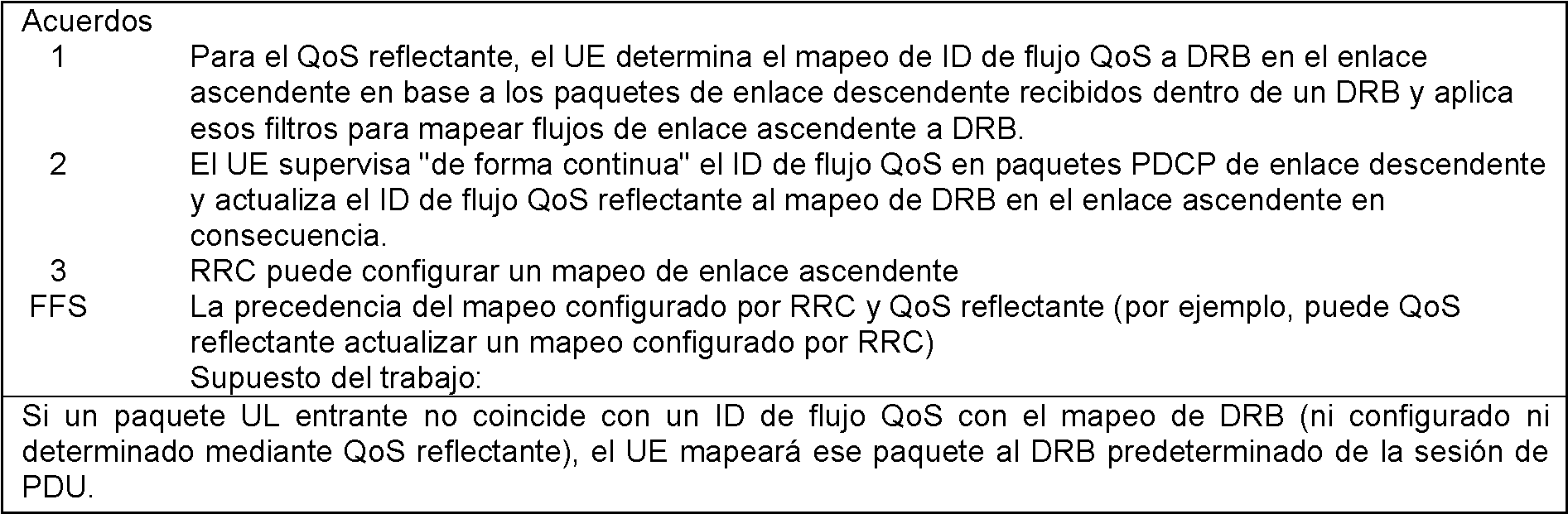
> FFS si el campo QoS es agregado por PDCP o una nueva capa de protocolo por encima de PDCP.> FFS if the QoS field is added by PDCP or a new protocol layer on top of PDCP.
RAN2 Ad-Hoc de enero de 2017:RAN2 Ad-Hoc from January 2017:

RAN2-97 Atenas:RAN2-97 Athens:


RAN2-97bis Spokane (abril de 2017)RAN2-97bis Spokane (April 2017)


El documento 3GPP R2-1707161 discutió la reasignación del flujo QoS dentro de la misma celda y en el traspaso de la siguiente manera:3GPP document R2-1707161 discussed QoS flow reassignment within the same cell and on handover as follows:
2.1 Actualización del flujo QoS a filtros DRB2.1 Upgrade QoS flow to DRB filters
En RAN2-96 se discutió cómo la red puede cambiar un mapeo de flujos UL a DRB y RAN2 acordó que "El UE" supervisa de forma continua "el ID de flujo QoS en paquetes PDCP de enlace descendente y actualiza el ID de flujo QoS reflectante al mapeo de DRB en el enlace ascendente en consecuencia". At RAN2-96 it was discussed how the network can change a UL flow mapping to DRB and RAN2 agreed that "The UE" continuously monitors "the QoS flow ID in downlink PDCP packets and updates the reflective QoS flow ID. to mapping DRB on the uplink accordingly. "
Las palabras "de forma continua" se ponen entre comillas porque las empresas querían estudiar si realmente todos y cada uno de los paquetes DL necesitaban ser analizados.The words "continuously" are put in quotes because the companies wanted to study whether each and every DL packet really needed to be analyzed.
Creemos que esta es la forma más sencilla de permitir que el eNB actualice el mapeo redirigiendo los paquetes de un flujo de DL a un DRB diferente. Por ejemplo, si el UE observa inicialmente un paquete de enlace descendente con ID de flujo X en DRB 1, crea un filtro "Flujo a DRB" que mapea paquetes de enlace ascendente con ID de flujo X a DRB 1. Pero si el UE observa posteriormente un paquete de enlace descendente con ID de flujo X en DRB 2, debería cambiar el filtro para el flujo X de modo que también los paquetes UL se mapeen a DRB 2. We think this is the simplest way to allow the eNB to update the mapping by redirecting packets from one DL stream to a different DRB. For example, if the UE initially observes a downlink packet with stream ID X in DRB 1, it creates a "Stream to DRB" filter that maps uplink packets with stream ID X to DRB 1. But if the UE observes subsequently a downlink packet with stream ID X in DRB 2, you should change the filter for stream X so that the UL packets are also mapped to DRB 2.
Mientras tanto, SA2 acordó sin embargo que el CN debería indicar dinámicamente en el encabezado del paquete N3 (plano de usuario) que el UE usará los encabezados de este paquete para crear o actualizar el mapeo de QoS reflectante del nivel NAS:In the meantime, SA2 agreed however that the CN should dynamically indicate in the header of the N3 packet (user plane) that the UE will use the headers of this packet to create or update the reflective QoS mapping of the NAS level:
Tabla 1: Arquitectura del sistema 3GPP TS23.501 para el sistema 5G, Stage2, V0.3.1 (2017-03)Table 1: 3GPP TS23.501 System Architecture for 5G System, Stage2, V0.3.1 (2017-03)

En base a la entrada de SA2 de que se les dirá a los UE si un paquete DL requiere una actualización del mapeo de SDF-to-flow de nivel NAS, sugerimos copiar esa indicación en el encabezado SDAP.Based on input from SA2 that UEs will be told if a DL packet requires a NAS-level SDF-to-flow mapping update, we suggest copying that indication into the SDAP header.
Propuesta 5 Si el bit NAS-RQI en un encabezado SDAP DL se establece en 1, el UE indica al NAS que determinará y posiblemente actualizará el mapeo SDF-a-Flujo en base al ID de flujo presente en el encabezado SDAP.Proposal 5 If the NAS-RQI bit in an SDAP DL header is set to 1, the UE indicates to the NAS that it will determine and possibly update the SDF-to-Stream mapping based on the stream ID present in the SDAP header.
Hasta ahora, RAN2 asumió que el UE actualizará el mapeo de flujo a DRB de nivel AS en base a todos los paquetes DL recibidos que contienen un ID de flujo. Se podría considerar cambiar esto para que el UE actualice también el mapeo de nivel AS solo si se le indica explícitamente que lo haga. Sin embargo, para lograr esto, el encabezado SDAP necesitaría comprender un segundo bit que indique por separado pero de manera similar si el UE actualizará el mapeo de flujo a DRB mediante el uso del ID de flujo en el encabezado del paquete. Obviamente, esto solo dejaría 6 bits para el ID de flujo y, por lo tanto, probablemente conduciría a encabezados SDAP de 2 octetos si se considera que 6 bits son demasiado pequeños. Se puede encontrar más discusión sobre los posibles formatos de encabezado en 0. En ese artículo llegamos a la conclusión de que el ID de flujo en el encabezado SDAP debería ser de 7 bits.Until now, RAN2 assumed that the UE will update the flow mapping to AS-level DRB based on all received DL packets containing a flow ID. You could consider changing this so that the UE also updates the AS level mapping only if it is explicitly instructed to do so. However, to achieve this, the SDAP header would need to comprise a second bit that separately but similarly indicates whether the UE will update the stream mapping to DRB by using the stream ID in the packet header. Obviously this would only leave 6 bits for the stream ID and thus would probably lead to 2-byte SDAP headers if 6 bits are considered to be too small. More discussion can be found on the possible 0 header formats. In that article we concluded that the stream ID in the SDAP header should be 7 bits.
Propuesta 6 La longitud del ID de flujo para DL y UL en el encabezado SDAP es de 7 bits.Proposal 6 The length of the stream ID for DL and UL in the SDAP header is 7 bits.
Propuesta 7 Dado que el bit NAS-RQI solo se necesita en los encabezados DL SDAP, el encabezado SDAP Ul tiene un bit de reserva (R).Proposal 7 Since the NAS-RQI bit is only needed in DL SDAP headers, the SDAP Ul header has a spare (R) bit.
2.2 Reordenamiento de paquetes al reasignar el flujo QoS a otro DRB2.2 Packet reordering when reassigning QoS flow to another DRB
Algunas empresas observaron en la última reunión que la reasignación de un flujo QoS a un DRB diferente puede provocar una entrega de paquetes fuera de secuencia. Esto puede suceder cuando los paquetes iniciales del flujo terminan en un DRB de baja prioridad y los paquetes subsiguientes se asignan a un DRB de alta prioridad debido a una asignación de flujo a d Rb actualizada. Estamos de acuerdo con esta observación, pero creemos que la red puede evitar esto al realizar el re-mapeo en una ocasión donde las colas están vacías. Sin embargo, puede que no siempre sea posible garantizar esto para la dirección del enlace ascendente. Pero al menos para la reasignación inicial de un DRB predeterminado a otro DRB, es probable que las capas superiores todavía estén en la fase de establecimiento de comunicación inicial (por ejemplo, TCP sYn/SYN-ACK, configuración de seguridad TLS, HTTP GET) y, por lo tanto, normalmente habrá Serán muy pocos paquetes en vuelo que puedan adelantarse unos a otros. Some companies noted in the last meeting that reassigning a QoS flow to a different DRB can lead to out-of-sequence packet delivery. This can happen when the initial packets in the flow end in a low priority DRB and subsequent packets are assigned to a high priority DRB due to an updated ad Rb flow assignment. We agree with this observation, but we believe that the network can avoid this by re-mapping on an occasion where the queues are empty. However, it may not always be possible to guarantee this for the uplink direction. But at least for the initial reassignment from a default DRB to another DRB, the upper layers are likely still in the initial handshake phase (e.g. TCP s AND n / SYN-ACK, TLS security settings, HTTP GET) and therefore there will usually be very few packets in flight that can overtake each other.
Observación 2 Cuando el NW vuelve a mapear un flujo a un DRB diferente durante la fase de transacción inicial del flujo, es poco probable que se reordenen los paquetes debido a que hay pocos paquetes en vuelo.Observation 2 When the NW remaps a flow to a different DRB during the initial transaction phase of the flow, it is unlikely that the packets will be reordered because there are few packets in flight.
Observación 3 Cuando el NW vuelve a mapear un flujo a un DRB diferente, puede minimizar el riesgo de reordenarlo posponiéndolo para ocasiones en donde los búferes están vacíos o al menos pequeños.Observation 3 When the NW remaps a stream to a different DRB, you can minimize the risk of reordering it by postponing it for occasions where the buffers are empty or at least small.
También se mencionó que el reordenamiento de paquetes en el re-mapeo del flujo podría evitarse mediante una función de reordenamiento adicional por flujo QoS (por encima de PDCP). Sin embargo, de acuerdo con las observaciones anteriores, no vemos la necesidad de una funcionalidad (compleja) en el lado de la UE.It was also mentioned that packet reordering in flow re-mapping could be avoided by an additional QoS flow reordering function (on top of PDCP). However, based on the observations above, we do not see a need for (complex) functionality on the EU side.
Si RAN2 cree que el riesgo de reordenar paquetes en la reasignación de QoS-Flow (en dirección de enlace ascendente) es inaceptablemente grande, sugerimos buscar una solución relativamente simple como la siguiente: Al detectar una reasignación de un flujo a un DRB diferente (de forma reflectante o explícita), el transmisor PDCP copias todas las PDU PDCP aún no RLC-ACKed a la entidad PDCP del DRB de destino. Esto puede resultar en algunos duplicados, pero esos no importan para las capas superiores. Dado que de todos modos asumimos que normalmente habrá solo unos pocos paquetes en vuelo durante la fase inicial de una transferencia de archivos, la ineficacia debido a los (pocos) duplicados sería insignificante para la reasignación del QoS reflectante inicial descrita anteriormente. Por supuesto, el enfoque también evitaría reordenar a nivel de IP si la red re-mapea un flujo durante el traspaso.If RAN2 believes that the risk of reordering packets in the QoS-Flow reassignment (in the uplink direction) is unacceptably large, we suggest looking for a relatively simple solution like the following: When detecting a reassignment of a flow to a different DRB (from reflective or explicit), the PDCP transmitter copies all PDCP PDUs not yet RLC-ACKed to the PDCP entity of the destination DRB. This can result in some duplicates, but those don't matter for the upper layers. Since we assume that there will normally be only a few packets in flight anyway during the initial phase of a file transfer, the Inefficiency due to the (few) duplicates would be negligible for the initial reflective QoS reassignment described above. Of course, the approach would also avoid reordering at the IP level if the network re-maps a flow during the handover.
Mover (en lugar de copiar) los datos a otro DRB evitaría la sobrecarga, pero requeriría volver a procesar las PDU PDCP ya procesadas previamente del DRB de origen.Moving (rather than copying) the data to another DRB would avoid overhead, but would require reprocessing the previously processed PDCP PDUs from the source DRB.
Propuesta 8 La funcionalidad adicional del UE para evitar una posible entrega fuera de orden cuando se vuelve a mapear un flujo QoS a un DRB diferente (mediante señalización explícita o mediante la actualización de la asignación del QoS reflectante) no debe ser presentado. Propuesta 9 Si la Propuesta 8 no es aceptable (es decir, si RAN2 cree que se evitará el reordenamiento debido a la reasignación del flujo QoS), el transmisor PDCP copiará todas las PDU PDCP que aún no hayan recibido el RLC ACK a la entidad PDCP del DRB de destino.Proposal 8 The additional functionality of the UE to avoid possible out-of-order delivery when remapping a QoS flow to a different DRB (by explicit signaling or by updating the reflective QoS assignment) should not be presented. Proposal 9 If Proposal 8 is not acceptable (i.e. if RAN2 believes that reordering will be avoided due to QoS flow reassignment), the PDCP transmitter will copy all PDCP PDUs that have not yet received the RLC ACK to the PDCP entity of the destination DRB.
2.3 Orden de precedencia del mapeo reflectante y configurado2.3 Order of precedence of reflective and configured mapping
RAN2-96 aún no está de acuerdo "La precedencia del mapeo configurado RRC y el QoS reflectante". Básicamente, hay tres opciones:RAN2-96 still disagrees "The precedence of the RRC configured mapping and reflective QoS". Basically, there are three options:
1) Un mapeo configurado por RRC anula cualquier mapeo reflectante para ese flujo.1) A mapping configured by RRC overrides any reflective mapping for that stream.
2) Un mapeo reflectante recién derivado anula un mapeo configurado previamente por RRC.2) A newly derived reflective mapping overrides a mapping previously configured by RRC.
3) El UE aplica siempre el mapeo más reciente, es decir, proporcionado por RRC o derivado por QoS reflectante3) The UE always applies the most recent mapping, i.e. provided by RRC or derived by reflective QoS
Creemos que la segunda opción introduciría una dependencia indeseable entre la configuración de RRC y el plano de usuario. Por ejemplo, la configuración RRC (AS-Config) no representaría el mapeo que aplica el UE. Esto sería indeseable en caso de movilidad, ya que el UE no se comportaría como espera el nodo objetivo. También eliminaría la posibilidad de anular un mapeo de QoS reflectante anterior mediante una configuración dedicada.We believe that the second option would introduce an undesirable dependency between the RRC configuration and the user plane. For example, the RRC configuration (AS-Config) would not represent the mapping applied by the UE. This would be undesirable in case of mobility, since the UE would not behave as expected by the target node. It would also eliminate the possibility of overriding a previous reflective QoS mapping using a dedicated configuration.
La tercera opción adolece de posibles condiciones de carrera ya que puede que no sea completamente predecible si el UE recibió primero un paquete de datos DL o la conexión/re configuración RRC. Además, al igual que la segunda opción, existen ambigüedades sobre la movilidad.The third option suffers from possible race conditions as it may not be completely predictable whether the UE first received a DL data packet or the RRC connection / reconfiguration. Furthermore, like the second option, there are ambiguities about mobility.
En general, pensamos que la señalización RRC siempre debe tener prioridad sobre la señalización de control L2 y L1. Esto aseguraría una división limpia y evitaría cualquier ambigüedad. Además, durante la movilidad, este principio asegura que el eNB objetivo sea consciente de todas las asignaciones de QoS de UL configuradas aplicadas por el UE. Además de eso, también permitiría al eNB mapear un flujo QoS DL en un DRB diferente al flujo QoS UL con el mismo ID.In general, we think that RRC signaling should always take priority over L2 and L1 control signaling. This would ensure a clean division and avoid any ambiguity. Furthermore, during mobility, this principle ensures that the target eNB is aware of all configured UL QoS assignments applied by the UE. Besides that, it would also allow the eNB to map a QoS DL stream to a different DRB to the QoS UL stream with the same ID.
Propuesta 10 Si el eNB configura el UE con un "filtro de flujo QoS de enlace ascendente a DRB", anula cualquier mapeo reflectante para este flujo QoS.Proposal 10 If the eNB configures the UE with an "uplink to DRB QoS flow filter", it overrides any reflective mapping for this QoS flow.
2.4 Mantener del mapeo de QoS durante el traspaso2.4 Maintain QoS mapping during handover
En el contexto de la movilidad entre celdas, debería discutirse si el UE mantiene los filtros de QoS UL reflectantes. Como se mencionó anteriormente, el eNB objetivo no conoce los filtros de QoS reflectantes del UE de AS-Config. Se podría considerar que el eNB de origen proporciona los mapeos de QoS de UL reflectantes al eNB de destino (por ejemplo, en AS-Context). Alternativamente, el nodo de destino puede cambiar el mapeo de QoS y enviar el nuevo mapeo al UE en el comando HO (conexión/re configuración RRC). Pero consideramos que esto es innecesariamente complejo y también introduciría un riesgo de desajuste entre los estados. Parece más sencillo que el UE mantenga un mapeo de QoS de UL reflectante siempre que exista el DRB con el que está asociado, es decir, también durante la movilidad normal de RRC. El UE libera el mapeo reflectante de UL QoS cuando el eNB libera el DRB con el que está asociado el mapeo.In the context of inter-cell mobility, it should be discussed whether the UE maintains reflective UL QoS filters. As mentioned above, the target eNB is not aware of the reflective QoS filters of the AS-Config UE. The source eNB could be considered to provide the reflective UL QoS mappings to the destination eNB (for example, in AS-Context). Alternatively, the destination node can change the QoS mapping and send the new mapping to the UE in the HO command (connect / reconfigure RRC). But we consider this to be unnecessarily complex and would also introduce a risk of mismatch between states. It seems simpler for the UE to maintain a reflective UL QoS mapping as long as the DRB with which it is associated exists, ie also during normal RRC mobility. The UE releases the reflective UL QoS mapping when the eNB releases the DRB with which the mapping is associated.
Propuesta 11 El UE mantiene un mapeo de QoS de UL reflectante mientras exista el DRB con el que está asociado, es decir, también durante la movilidad normal de RRC y tras el cambio de tipo de portador. El UE libera el mapeo reflectante de UL QoS cuando el eNB libera el DRB con el que está asociado el mapeo.Proposal 11 The UE maintains a reflective UL QoS mapping as long as the DRB with which it is associated exists, ie also during normal RRC mobility and after carrier type change. The UE releases the reflective UL QoS mapping when the eNB releases the DRB with which the mapping is associated.
La nota del presidente de RAN2#98 capturó los siguientes acuerdos realizados para la QoS relacionada: RAN2 President's Note # 98 captured the following agreements made for related QoS:


La nota del presidente de RAN2 NR Ad Hoc #2 capturó los siguientes acuerdos realizados para la QoS relacionada:RAN2 NR Ad Hoc Chairman's Note # 2 captured the following deals made for related QoS:


El borrador de 3GPP TS 37.324 especificó el procedimiento de transferencia de datos SDAP y el mapeo del flujo QoS a DRB (portador de radio de datos) de la siguiente manera:The 3GPP TS 37.324 draft specified the SDAP data transfer procedure and QoS flow mapping to DRB (data radio bearer) as follows:
5.2 Procedimientos de transferencia de datos SDAP5.2 SDAP data transfer procedures
5.2.1 Procedimientos de transferencia de datos UL5.2.1 UL data transfer procedures
Al recibir una SDAP SDU de la capa superior para un flujo QoS, When receiving an SDAP SDU from the upper layer for a QoS flow,
- si no hay un flujo QoS almacenado a la regla de mapeo de DRB para el flujo QoS:- if there is no stored QoS flow to the DRB mapping rule for the QoS flow:
- la entidad SDAP correlacionará la SDU del SDAP con el portador por defecto;- the SDAP entity shall map the SDAP of the SDAP to the default bearer;
- de lo contrario:- otherwise:
- la entidad SDAP correlacionará la SDU del SDAP con el DRB de acuerdo con el flujo QoS almacenado con la regla de correlación DRB;- the SDAP entity will map the SDU of the SDAP to the DRB according to the QoS flow stored with the DRB mapping rule;
- si el DRB al que se asigna esta SDAP SDU está configurado por la capa superior [3] con la presencia de un encabezado SDAP,- if the DRB to which this SDAP SDU is assigned is configured by the upper layer [3] with the presence of an SDAP header,
- la entidad SDAP construirá la PDU del SDAP como se especifica en la subcláusula 6.2.2.2;- the SDAP entity shall construct the SDAP PDU as specified in subclause 6.2.2.2;
- de lo contrario:- otherwise:
- la entidad SDAP construirá la PDU del SDAP como se especifica en la subcláusula 6.2.2.1;- the SDAP entity shall construct the SDAP PDU as specified in subclause 6.2.2.1;
- la entidad SDAP entregará la PDU del SDAP a las capas inferiores.- the SDAP entity shall deliver the SDAP PDU to the lower layers.
5.2.2 Procedimientos de transferencia de datos DL5.2.2 DL data transfer procedures
En la recepción de una PDU del SDAP de capas inferiores,On receipt of a lower layer SDAP PDU,
- si el DRB desde el que se recibe esta PDU del SDAP está configurado por la capa superior [3] con la presencia de un encabezado SDAP, la entidad SDAP deberá:- if the DRB from which this SDAP PDU is received is configured by the upper layer [3] with the presence of an SDAP header, the SDAP entity shall:
- realizar la correspondencia de flujo QoS reflectante a DRB como se especifica en el apartado 5.3.2;- map reflective QoS flow to DRB as specified in 5.3.2;
- recuperar la SDU del SDAP de la PDU del SDAP como se especifica en la subcláusula 6.2.2.2;- retrieve the SDAP SDU from the SDAP PDU as specified in subclause 6.2.2.2;
- de lo contrario:- otherwise:
- recuperar la SDU del SDAP del PDU del SDAP como se especifica en la subcláusula 6.2.2.1;- retrieve the SDAP SDU from the SDAP PDU as specified in subclause 6.2.2.1;
- entregar la SDU del SDAP recuperada a la capa superior.- deliver the recovered SDAP SDU to the upper layer.
5.3 Procedimiento de mapeo de flujo QoS a DRB5.3 QoS to DRB flow mapping procedure
5.3.1 Configuración de mapeo de flujo QoS a DRB5.3.1 QoS to DRB flow mapping configuration
Cuando la capa superior [3] configura un flujo QoS UL a la regla de mapeo DRB para una entidad SDAP:When the upper layer [3] configures a UL QoS flow to the DRB mapping rule for an SDAP entity:
- la entidad SDAP almacenará el flujo QoS de UL a la regla de mapeo de DRB.- the SDAP entity will store the UL QoS flow to the DRB mapping rule.
5.3.2 flujo QoS reflectante al mapeo DRB5.3.2 reflective QoS flow to DRB mapping
Para cada paquete DL recibido del flujo QoS, el UE comprobará el encabezado SDAP para el mapeo de QoS reflectante a DRB, como sigue:For each DL packet received from the QoS flow, the UE will check the SDAP header for reflective QoS to DRB mapping, as follows:
- si se promulga el flujo QoS reflectante al mapeo de DRB:- if reflective QoS flow is enacted to DRB mapping:
la entidad SDAP almacenará el flujo QoS al mapeo DRB del paquete DL como el flujo QoS a la regla de mapeo DRB para los paquetes UL del flujo QoS.the SDAP entity shall store the QoS flow to the DL packet DRB mapping as the QoS flow to the DRB mapping rule for the UL packets of the QoS flow.
El documento de 3GPP R2-1704648 propuso usar una PDU de control SDAP (Unidad de datos de protocolo) para configurar el flujo QoS a la asignación de DRB de la siguiente manera:3GPP document R2-1704648 proposed to use SDAP (Protocol Data Unit) Control PDU to configure QoS flow to DRB mapping as follows:
2.1 Notificación reflectante en Uu2.1 Reflective notice in the Uu
Por logro capturado en [1] (anexo A como referencia), la RAN puede controlar el mapeo de enlace ascendente de flujo QoS a DRB ya sea mediante mapeo reflectante o configuración explícita. Y el mapeo reflectante se logra marcando paquetes DL sobre Uu con QFI (en adelante, denominado mapeo reflectante a través de PDU de datos SDAP).By achievement captured in [1] (Annex A for reference), the RAN can control the uplink mapping of QoS flow to DRB either by reflective mapping or explicit configuration. And reflective mapping is achieved by marking DL packets over Uu with QFI (hereinafter referred to as reflective mapping via SDAP data PDU).
La posibilidad de admitir la reasignación de DRB-flujo QoS se planteó durante la SI sin una decisión final. El problema se analiza en nuestra contribución complementaria y proponemos que se permita la reasignación de DRB de flujo QoS para casos de no traspaso (es decir, reasignación intracelular). Luego, de acuerdo con el logro indicado anteriormente, la RAN puede controlar la reasignación de DRB de flujo QoS de enlace ascendente mediante configuración explícita o mapeo reflectante a través de la PDU de datos SDAP. Sin embargo, tome el siguiente caso de reasignación enumerado en [2] como ejemplo:The possibility of supporting DRB-QoS flow reassignment was raised during the SI without a final decision. The problem is discussed in our companion contribution and we propose that QoS flow DRB reassignment be allowed for non-handover cases (i.e. intracellular reassignment). Then, according to the achievement stated above, the RAN can control the uplink QoS flow DRB reassignment by explicit configuration or reflective mapping via the SDAP data PDU. However, take the following remapping case listed in [2] as an example:
- Si un paquete de UL entrante no coincide con un "ID de flujo QoS para mapeo de DRB", el UE mapeará el paquete con el DRB por defecto de la sesión de PDU. Cuando el gNB recibe el paquete, puede decidir reasignar el flujo QoS UL a otro DRB apropiado.- If an incoming UL packet does not match a "QoS flow ID for DRB mapping", the UE will map the packet to the default DRB of the PDU session. When the gNB receives the packet, it may decide to reassign the UL QoS flow to another appropriate DRB.
Si el gNB controla la reasignación a través de una configuración explícita, se introducirán una sobrecarga de señalización de RRC adicional y un retardo adicional. Si bien si el gNB controla la reasignación a través de la PDU de datos SDAP, debe tenerse en cuenta que para UL principalmente tráfico, tal vez no haya llegada de datos DL en ese momento. Entonces, el control de la reasignación puede retrasarse hasta la llegada del primer paquete DL. El retraso impredecible puede tener un impacto negativo en la experiencia del usuario. El análisis anterior también es válido para los otros tres casos de reasignación enumerados en [2].If the gNB controls reassignment through an explicit configuration, additional RRC signaling overhead and additional delay will be introduced. While if the gNB controls reassignment via the SDAP data PDU, it should be noted that for UL primarily traffic, there may be no DL data arrival in that moment. Then, the reassignment control can be delayed until the arrival of the first DL packet. The unpredictable lag can have a negative impact on the user experience. The above analysis is also valid for the other three reassignment cases listed in [2].
Para abordar el problema, un enfoque posible es introducir una PDU de control SDAP para el mapeo reflectante de enlace ascendente (en adelante, denominada PDU de control SDAP para el mapeo reflectante). Por ejemplo, si se mapea un flujo QoS a un DRB a través de la PDU de control de SDAP, la QFI del flujo QoS debe incluirse en la PDU de control de SDAP y la PDU de control de SDAP se envía a través del DRB al que se espera que el flujo QoS sea asignado.To address the problem, one possible approach is to introduce an SDAP control PDU for uplink reflective mapping (hereinafter referred to as an SDAP control PDU for reflective mapping). For example, if a QoS flow is mapped to a DRB through the SDAP control PDU, the QFI of the QoS flow must be included in the SDAP control PDU and the SDAP control PDU is sent through the DRB to the that the QoS flow is expected to be allocated.
- La PDU de control SDAP para mapeo reflectante se puede introducir además del mapeo reflectante a través de la PDU de datos SDAP: Cuando el gNB decide controlar el mapeo/reasignación de enlace ascendente de QoS Flow-DRB a través del mapeo reflectante, si no hay datos DL disponibles en ese momento, el control a través de la PDU de control SDAP o el control mediante la p Du de datos SDAP o,- SDAP control PDU for reflective mapping can be entered in addition to reflective mapping via SDAP data PDU: When gNB decides to control QoS Flow-DRB uplink mapping / reassignment via reflective mapping, if not DL data is currently available, control via the SDAP control PDU or control via the SDAP data p D u or,
- La PDU de control SDAP para mapeo reflectante se puede introducir en lugar del mapeo reflectante a través de la PDU de datos SDAP: Siempre que el gNB decida controlar el mapeo/reasignación de enlace ascendente de QoS Flow-DRB a través del mapeo reflectante, control a través de la PDU de control SDAP.- SDAP control PDU for reflective mapping can be entered instead of reflective mapping via SDAP data PDU: As long as the gNB decides to control QoS Flow-DRB uplink mapping / reassignment via reflective mapping, control via the SDAP Control PDU.
Durante el estudio en SI, la mayoría de las empresas proponen desacoplar la QoS reflectante NAS y el mapeo reflectante AS. El objetivo se puede lograr con la introducción de la PDU de control SDAP que reemplaza el mapeo reflectante a través de la PDU de datos SDAP. Y si se acuerda introducir la PDU de control SDAp para mapeo reflectante, el formato de la PDU de control SDAP se puede encontrar en nuestra contribución complementaria. Observación 1. Si con la introducción de la PDU de control SDAP para reemplazar el mapeo reflectante a través de la PDU de datos SDAP, se puede lograr el objetivo de desacoplar la QoS reflectante NAS y la cartografía reflectante AS.During SI study, most companies propose decoupling NAS reflective QoS and AS reflective mapping. The goal can be achieved with the introduction of the SDAP control PDU which replaces reflective mapping through the SDAP data PDU. And if it is agreed to introduce the SDAp control PDU for reflective mapping, the format of the SDAP control PDU can be found in our supplementary contribution. Remark 1. If with the introduction of the SDAP control PDU to replace the reflective mapping through the SDAP data PDU, the goal of decoupling the NAS reflective QoS and AS reflective mapping can be achieved.
Con el análisis anterior, proponemos:With the previous analysis, we propose:
Propuesta1 Introducir la PDU de control SDAP para mapeo reflectante.Proposal1 Introduce the SDAP control PDU for reflective mapping.
Propuesta 2. La PDU de control SDAP se puede introducir para reemplazar o adicional al mapeo reflectante a través de la PDU de datos SDAP.Proposal 2. The SDAP control PDU can be introduced to replace or in addition to reflective mapping via the SDAP data PDU.
En RAN2#97bis [3], se acuerda que:In RAN2 # 97bis [3], it is agreed that:
- Los paquetes DL sobre Uu no están marcados con "ID de flujo" al menos para los casos en donde el mapeo reflectante UL AS y la QoS reflectante NAS no están configurados para DRB. - DL packets over Uu are not marked with "stream ID" at least for cases where UL AS reflective mapping and NAS reflective QoS are not configured for DRB.
Entonces, la pregunta es ¿cuándo deben marcarse los paquetes DL sobre Uu con "ID de flujo"?So the question is when should DL packets over Uu be marked with "stream ID"?
De acuerdo con el logro en SA2 [4] (Anexo B como referencia), si se usa la QoS reflectante NAS, el UE necesita confiar en los paquetes DL para derivar las reglas de QoS. La regla de QoS derivada incluye el filtro de paquetes, QFI, valor de precedencia. Entre las reglas de QoS derivadas, el filtro de paquetes y QFI solo pueden derivarse de los paquetes DL. Entonces, obviamente, el QFI también debería incluirse en los paquetes DL con el propósito de QoS reflectante NAS.According to the achievement in SA2 [4] (Annex B for reference), if the reflective QoS NAS is used, the UE needs to trust the DL packets to derive the QoS rules. Derived QoS rule includes packet filter, QFI, precedence value. Among derived QoS rules, packet filter and QFI can only be derived from DL packets. So obviously the QFI should also be included in the DL packets for the purpose of reflective QoS NAS.
Observación 2. Los paquetes DL sobre Uu deben marcarse con QFI para el propósito de QoS reflectante NAS.Remark 2. DL packets over Uu must be marked with QFI for NAS reflective QoS purpose.
La QoS reflectante del NAS es crear una regla de QoS para un flujo QoS de enlace ascendente en el UE. Y por logro en [1], el momento para establecer los DRB no predeterminados y cómo mapear los flujos QoS a DRB depende de la decisión de RAN. En el momento de crear una regla de QoS para un flujo QoS de enlace ascendente a través de QoS reflectante NAS, lo más probable es que haya próximos paquetes de enlace ascendente para este flujo QoS específico. Si el flujo QoS no está mapeado a ningún DRB en ese momento, el mapeo reflectante AS puede usarse al mismo tiempo para mapear este flujo QoS de enlace ascendente específico a un DRB establecido. En este caso, si se sigue usando la PDU de datos SDAP para el mapeo reflectante AS, QFI debe incluirse en los paquetes DL tanto para el propósito de QoS reflectante NAS como para el mapeo reflectante AS.The reflective QoS of the NAS is to create a QoS rule for an uplink QoS flow in the UE. And by achievement in [1], the timing to set the non-default DRBs and how to map the QoS flows to DRB depends on the RAN decision. At the time of creating a QoS rule for an uplink QoS flow via NAS reflective QoS, chances are there will be upcoming uplink packets for this specific QoS flow. If the QoS flow is not currently mapped to any DRB, the reflective mapping AS can be used at the same time to map this specific uplink QoS flow to an established DRB. In this case, if the SDAP data PDU is still used for reflective AS mapping, QFI must be included in the DL packets for both the purpose of reflective QoS NAS and reflective AS mapping.
Observación 3. La QoS reflectante NAS y el mapeo reflectante AS pueden tener lugar simultáneamente sobre la Uu.Remark 3. NAS reflective QoS and AS reflective mapping can take place simultaneously over Uu.
Observación 4. Si sigue usando la PDU de datos SDAP con el propósito de QoS reflectante AS, los paquetes DL sobre Uu deben marcarse con QFI para el propósito de QoS reflectante NAS y/o mapeo reflectante AS. Remark 4. If you continue to use the SDAP data PDU for the purpose of reflective AS QoS, DL packets over Uu should be marked with QFI for the purpose of reflective QoS NAS and / or reflective AS mapping.
Con la introducción de QFI en paquetes DL con el propósito de reflejar, si el UE debe monitorear "de forma continua" el QFI en paquetes DL o no, se deja abierto al final de la fase SI. Teniendo en cuenta el alto volumen de datos en NR, surge la preocupación de que se introducirá una alta sobrecarga de procesamiento así como complejidad si se requiere que el UE supervise de forma continua el ID de flujo QoS en cada paquete DL [5]. Además, como se analizó anteriormente, si se sigue usando la PDU de datos SDAP con el propósito de QoS reflectante AS, el QFI debe incluirse en los paquetes DL con el propósito de QoS reflectante nAs y mapeo reflectante AS. Entonces, si solo tiene QFI en los paquetes DL, el UE que recibe un paquete DL con QFI no puede discriminar si es para QoS reflectante NAS o mapeo reflectante AS, por lo que debe realizar ambos tipos de verificación reflectante en cualquier momento. De esta forma, se introducirá una sobrecarga de procesamiento innecesaria.With the introduction of QFI on DL packets for the purpose of reflecting, whether the UE should "continuously" monitor the QFI on DL packets or not is left open at the end of the SI phase. Considering the high data volume in NR, concern arises that high processing overhead as well as complexity will be introduced if the UE is required to continuously monitor the QoS flow ID in each DL packet [5]. Moreover, as discussed above, if followed using SDAP PDU data for the purpose of reflecting QoS AS, the QFI be included in the DL packet for the purpose of reflecting QoS n A s and reflective mapping AS. So if you only have QFI on DL packets, the UE receiving a DL packet with QFI cannot discriminate whether it is for NAS reflective QoS or AS reflective mapping, so it has to perform both types of reflective check at any time. This will introduce unnecessary processing overhead.
Para abordar los problemas anteriores, se deben introducir indicadores en los paquetes DL para informar a UE si el QFI está incluido en los paquetes DL o no y si es para QoS reflectante nAs y/o mapeo reflectante AS. El UE necesita realizar una verificación reflexiva solo si se indica que el QFI está incluido. Y el UE realiza una comprobación reflectante NAS y/o comprobación reflectante AS de acuerdo con las instrucciones de los indicadores. El detalle de la inclusión de los indicadores en el encabezado SDAP se discutirá en nuestra contribución complementaria [6].To address the above issues, flags should be introduced in DL packets to inform UE if QFI is included in DL packets or not and if it is for reflective QoS n A s and / or reflective mapping AS. The UE needs to perform a thoughtful check only if the QFI is indicated to be included. And the UE performs a NAS reflective check and / or AS reflective check according to the instructions of the indicators. The detail of the inclusion of the indicators in the SDAP header will be discussed in our supplementary contribution [6].
Propuesta 3. Si se sigue usando la PDU de datos SDAP con el propósito de QoS reflectante AS, se deben introducir indicadores en los paquetes DL para informar si QFI está incluido o no y si es para QoS reflectante NAS y/o mapeo reflectante AS.Proposal 3. If the SDAP data PDU is still used for the purpose of reflective AS QoS, flags should be introduced in the DL packets to inform whether or not QFI is included and whether it is for NAS reflective QoS and / or AS reflective mapping.
Para el mapeo reflectante de AS, el mapeo de flujo QoS a DRB se determina por el propio gNB, depende de gNB determinar cuándo hacer uso del mapeo reflectante de AS. Por lo tanto, el gNB sabe bien cuándo se requiere el mapeo reflectante AS y genera la p Du de control SDAP o la PDU de datos SDAP para el mapeo reflectante en consecuencia.For reflective AS mapping, QoS to DRB flow mapping is determined by the gNB itself, it is up to gNB to determine when to make use of reflective AS mapping. Thus, the gNB knows well when reflective mapping AS is required and generates SDAP control p Du or SDAP data PDU for reflective mapping accordingly.
Mientras que para la QoS reflectante NAS, por logro en SA2 [4], la QoS reflectante se puede activar a través del plano de usuario o el plano de control a través de la indicación de QoS reflectante (RQI). Si se activa a través del plano de usuario, el RQI se incluirá en el encabezado de encapsulación de los paquetes DL en el punto de referencia N3. Con la recepción de RQI, el gNB sabe que se requiere el QoS reflectante NAS e incluye el QFI en los paquetes DL en consecuencia. Si se activa a través del plano de control, el RQI solo se indica al UE a través del punto de referencia N1 [4]. El gNB no tiene idea de cuándo incluir el QFI en los paquetes DL. Por lo tanto, se debe informar a SA2 que para el caso de QoS reflectante activada a través del plano de control, el RQI también debe ser informado al gNB, por ejemplo, a través de la señalización N2.Whereas for NAS reflective QoS, by achievement in SA2 [4], reflective QoS can be activated via user plane or control plane via Reflective QoS Indication (RQI). If enabled via the user plane, the RQI will be included in the encapsulation header of the DL packets at the N3 reference point. With the receipt of RQI, the gNB knows that the reflective QoS NAS is required and includes the QFI in the DL packets accordingly. If activated via the control plane, the RQI is only indicated to the UE via the N1 reference point [4]. The gNB has no idea when to include the QFI in the DL packets. Therefore, SA2 must be informed that for the case of reflective QoS activated via the control plane, the RQI must also be informed to the gNB, eg via N2 signaling.
Propuesta 4. Informar a SA2 que el RQI debe ser informado al gNB también en caso de que la QoS reflectante se active a través del plano de control.Proposal 4. Inform SA2 that the RQI should be informed to the gNB also in case the reflective QoS is activated through the control plane.
2.2 Precedencia del mapeo configurado por RRC y el mapeo reflectante2.2 Precedence of mapping configured by RRC and reflective mapping
La precedencia del mapeo configurado por RRC y el mapeo reflectante AS aún se deja abierta ahora [1]. Durante la discusión en SI, se discute la solución del problema pero sin considerar la ocurrencia del problema en sí, es decir, en qué escenarios ocurrirá el problema. La suposición razonable es que una vez que se decida el mapeo de DRB de flujo QoS en el gNB, se mantendrá en uso sólo si se necesita reasignación de DRB de flujo QoS. En otras palabras, la cuestión de la precedencia del mapeo reflectante y configurado por RRC solo debe considerarse si se permite la reasignación del flujo QoS-DRB.The precedence of the mapping configured by RRC and reflective mapping AS is still left open now [1]. During the discussion in SI, the solution of the problem is discussed but without considering the occurrence of the problem itself, that is, in which scenarios the problem will occur. The reasonable assumption is that once the QoS flow DRB mapping is decided in the gNB, it will remain in use only if QoS flow DRB reassignment is needed. In other words, the RRC-configured and reflective mapping precedence issue should only be considered if QoS-DRB flow reassignment is allowed.
Propuesta 5. La cuestión de la precedencia del mapeo reflectante y configurado por RRC sólo debe considerarse si se permite la reasignación de flujo QoS a DRB.Proposal 5. The issue of reflective and RRC-configured mapping precedence should only be considered if reassignment of QoS flow to DRB is allowed.
El gNB decide el mapeo del flujo QoS a DRB de acuerdo con los perfiles de QoS por flujo QoS, teniendo en cuenta la condición de radio en RAN (por ejemplo, calidad del enlace de radio, condición de carga, etc.). Ni los perfiles de QoS ni las condiciones de radio en RAN cambiarán con frecuencia. Por lo tanto, se puede evitar que se lleve a cabo otra reasignación de flujo QoS a DRB inmediatamente después de la anterior. En otras palabras, prácticamente, el gNB iniciará una nueva reasignación solo después de la finalización de la reasignación anterior. Y el gNB conoce claramente el mapeo de DRB de flujo QoS más actualizado en UE. Dado lo anterior, proponemos que el UE siempre debe aplicar el mapeo más reciente, es decir, ya sea explícitamente proporcionado por RRC o derivado por mapeo reflectante.The gNB decides the mapping of the QoS flow to DRB according to the QoS profiles per QoS flow, taking into account the radio condition in RAN (eg quality of the radio link, load condition, etc.). Neither QoS profiles nor radio conditions in RAN will change frequently. Therefore, another QoS flow reassignment to DRB can be prevented from taking place immediately after the previous one. In other words, practically, the gNB will initiate a new reallocation only after the completion of the previous reallocation. And the gNB clearly knows the most up-to-date QoS flow DRB mapping in UE. Given the above, we propose that the UE should always apply the most recent mapping, that is, either explicitly provided by RRC or derived by reflective mapping.
Propuesta 6. El UE siempre debería aplicar el mapeo más reciente, es decir, ya sea explícito proporcionado por RRC o derivado por mapeo reflectante.Proposal 6. The UE should always apply the most recent mapping, ie either explicit provided by RRC or derived by reflective mapping.
2.3 Manejo del mapeo del flujo QoS a DRB durante el traspaso2.3 Handling QoS to DRB flow mapping during handover
De acuerdo con el acuerdo en RAN2#97bis, "Lossless HO" se puede lograr si el objetivo usa la misma configuración de DRB y el mismo mapeo de DRB de flujo QoS como fuente. Por lo tanto, para el propósito de "Lossless HO", toda la información de mapeo DRB de flujo QoS en el origen debe enviarse al destino. Y el UE debe mantener todo el mapeo DRB de flujo QoS adquirido de la fuente (incluyendo tanto el mapeo configurado a través de la señalización RRC como el mapeo reflectante) durante el traspaso y la actualización de acuerdo con la decisión de destino correspondiente.According to the agreement in RAN2 # 97bis, "Lossless HO" can be achieved if the target uses the same DRB configuration and the same QoS flow DRB mapping as the source. Therefore, for the purpose of "Lossless HO", all the QoS flow DRB mapping information at the source should be sent to the destination. And the UE should keep all the acquired QoS flow DRB mapping from the source (including both the mapping configured through RRC signaling and reflective mapping) during handover and update according to the corresponding destination decision.
Propuesta 7. Reenviar toda la información de mapeo DRB de flujo QoS desde el origen al destino.Proposal 7. Forward all QoS flow DRB mapping information from source to destination.
Propuesta 8. El UE debe mantener todo el mapeo de DRB de flujo QoS adquirido de la fuente durante el traspaso y actualizarlo de acuerdo con la decisión de destino correspondiente.Proposal 8. The UE should keep all the QoS flow DRB mapping acquired from the source during the handover and update it according to the corresponding destination decision.
De acuerdo con 3GPP TS 23.501, el flujo QoS es generalmente la mejor granularidad de diferenciación de QoS en la sesión de PDU. La sesión de PDU proporciona una asociación entre un UE y una red de datos que proporciona un servicio de conectividad de PDU.According to 3GPP TS 23.501, the QoS flow is generally the best QoS differentiation granularity in the PDU session. The PDU session provides an association between a UE and a data network that provides a PDU connectivity service.
De acuerdo con 3GPP TS 38.300, se especifica una nueva capa AS (estrato de acceso), llamada SDAP (Protocolo de adaptación de datos de servicio), para proporcionar funciones, por ejemplo, mapeo entre un flujo QoS y un portador de radio de datos (DRB) y marcar el ID de flujo QoS (QFI) tanto en paquetes DL como en paquetes UL. Además, cada entidad SDAP está asociada con una sesión de PDU. Hay al menos un DRB (por ejemplo, DRB predeterminado) para cada sesión de PDU. Cada PDU del SDAP puede contener al menos un paquete IP. Cada PDU del SDAP puede contener un encabezado SDAP (si está configurado para UL y/o DL). El encabezado SDAP puede indicar al menos un QFI usado para identificar un flujo QoS para el que el paquete IP proviene del flujo QoS. Una PDU de SDAP podría ser una s Du de PDCP. Además, la red puede controlar el mapeo de flujo(s) de QoS a DRB en mapeo explícito RRC o mapeo reflectante.According to 3GPP TS 38.300, a new layer AS (access stratum), called SDAP (Service Data Adaptation Protocol), is specified to provide functions, for example, mapping between a QoS flow and a data radio bearer (DRB) and mark the QoS flow ID (QFI) on both DL packets and UL packets. Furthermore, each SDAP entity is associated with a PDU session. There is at least one DRB (eg, default DRB) for each PDU session. Each SDAP PDU can contain at least one IP packet. Each SDAP PDU can contain an SDAP header (if configured for UL and / or DL). The SDAP header can indicate at least one QFI used to identify a QoS flow for which the IP packet comes from the QoS flow. An SDAP PDU could be a PDCP Du s. Furthermore, the network can control the mapping of flow (s) from QoS to DRB in explicit RRC mapping or reflective mapping.
En general, se supone que cada flujo QoS puede configurarse para usar un DRB mediante el mapeo explícito o el mapeo reflectante de RRC (Control de recursos de radio). Si un DRB (por ejemplo, DRB predeterminado o DRB no predeterminado/dedicado) sirve solo un flujo QoS UL, la red puede no configurar el DRB con la presencia de un encabezado SDAP para UL, lo que reduce la sobrecarga de señalización y ahorra recursos de radio.In general, it is assumed that each QoS flow can be configured to use a DRB by explicit mapping or RRC (Radio Resource Control) reflective mapping. If a DRB (e.g. default DRB or non-default / dedicated DRB) serves only one UL QoS stream, the network may not configure the DRB with the presence of an SDAP header for UL, reducing signaling overhead and saving resources radio.
La Figura 6, que es una reproducción de la Figura A.6-1 de 3GPP TS 38.300 v04.1, ilustra un escenario de flujo QoS de UL iniciado por UE. El UE inicia un nuevo flujo QoS de UL (el segundo flujo QoS de UL), por ejemplo, en base a parámetros de QoS pre configurados. Si no hay mapeo del QFI a un DRB en la tabla de mapeo AS para esta sesión de PDU, el segundo flujo QoS de UL se mapeará a un DRB predeterminado de la sesión de PDU. En caso de que ya exista un flujo QoS UL en curso (el primer flujo QoS UL) asignado a este DRB predeterminado y el DRB predeterminado no está configurado con la presencia del encabezado SDAP para UL actualmente, el gNB no conocerá del segundo flujo QoS UL cuando se reciben las PDU UL SDAP correspondientes al segundo flujo QoS UL del UE. En esta situación, la QoS objetivo del segundo flujo QoS de UL no se cumpliría porque gNB no establecería un nuevo DRB para el segundo flujo QoS ni mapearía el segundo flujo QoS a un DRB existente de acuerdo con los parámetros de QoS del segundo flujo QoS. Además, los paquetes IP incluidos en esas PDU del SDAP del segundo flujo QoS UL no serían distinguidos por la red central (por ejemplo, UPF) porque el filtro de paquetes corresponde al primer flujo QoS UL. Como resultado, los paquetes IP se descartarían, lo que provocaría la pérdida de datos y el desperdicio de recursos.Figure 6, which is a reproduction of 3GPP TS 38.300 v04.1 Figure A.6-1, illustrates a UE initiated UL QoS flow scenario. The UE initiates a new UL QoS flow (the second UL QoS flow), for example, based on pre-configured QoS parameters. If there is no mapping of the QFI to a DRB in the AS mapping table for this PDU session, the second UL QoS flow will map to a default DRB of the PDU session. In case there is already an ongoing UL QoS flow (the first UL QoS flow) assigned to this default DRB and the default DRB is not configured with the presence of the SDAP header for UL currently, the gNB will not know of the second UL QoS flow when the UL SDAP PDUs corresponding to the second UL QoS flow from the UE are received. In this situation, the target QoS of the second UL QoS flow would not be met because gNB would not establish a new DRB for the second QoS flow or map the second QoS flow to an existing DRB according to the QoS parameters of the second QoS flow. Furthermore, the IP packets included in those SDAP PDUs of the second UL QoS flow would not be distinguished by the core network (eg UPF) because the packet filter corresponds to the first UL QoS flow. As a result, IP packets would be dropped, leading to data loss and wasted resources.
Se podrían considerar varias soluciones que se describen a continuación.Several solutions could be considered which are described below.
Alternativa 1: El UE indica preferencia/necesidad de presencia de encabezado SDAPAlternative 1: UE indicates preference / need for SDAP header presence
Dado que el UE sabe si un DRB debe servir a múltiples flujos QoS de UL, el UE comprende si se necesita la presencia de un encabezado SDAP en el DRB. En caso de que el UE inicie el segundo flujo QoS de UL, el UE sabe que el DRB predeterminado configurado actualmente sin presencia de encabezado SDAP servirá al primer flujo QoS de UL existente y al segundo flujo QoS de UL. En este momento, el UE podría transmitir una primera indicación al gNB para indicar que se necesita la presencia de un encabezado SDAP en el DRB predeterminado. En base a la primera indicación, el gNB re configura el DRB predeterminado con la presencia del encabezado SDAP. En caso de que el UE libere el segundo flujo QoS de UL, el UE podría transmitir una segunda indicación al gNB para indicar que la presencia del encabezado SDAP en el DRB predeterminado no es necesaria. En base a la segunda indicación, el gNB re configura el DRB predeterminado sin presencia de encabezado SDAP. La primera indicación y/o la segunda indicación podrían enviarse mediante, por ejemplo, señalización física, elemento de control de MAC, señalización PDCP (Protocolo de convergencia de datos de paquetes), señalización RRC o señalización SDAP (por ejemplo, PDU de control SDAP). La primera indicación y la segunda indicación también podrían indicar la preferencia/necesidad de presencia del encabezado SDAp en un DRB no predeterminado (por ejemplo, un segundo DRB).Since the UE knows whether a DRB should serve multiple UL QoS flows, the UE understands whether the presence of an SDAP header is required in the DRB. In case the UE initiates the second UL QoS flow, the UE knows that the currently configured default DRB with no SDAP header presence will serve the first existing UL QoS flow and the second UL QoS flow. At this time, the UE could transmit a first indication to the gNB to indicate that the presence of an SDAP header is required in the predetermined DRB. Based on the first indication, the gNB re-configures the default DRB with the presence of the SDAP header. In case the UE releases the second UL QoS flow, the UE could transmit a second indication to the gNB to indicate that the presence of the SDAP header in the default DRB is not necessary. Based on the second prompt, the gNB re-configures the default DRB with no SDAP header present. The first indication and / or the second indication could be sent by, for example, physical signaling, MAC control element, PDCP (Packet Data Convergence Protocol) signaling, RRC signaling, or SDAP signaling (e.g., SDAP control PDU ). The first indication and the second indication could also indicate the preference / need for the presence of the SDA header p in a non-predetermined DRB (eg, a second DRB).
Alternativa 2: El UE proporciona información sobre el establecimiento o la liberación de un flujo QoS iniciado por UE Alternative 2: The UE provides information on the establishment or release of a UE initiated QoS flow
En caso de que el UE inicie el segundo flujo QoS de UL, el UE podría transmitir una primera información de asistencia al gNB para informar que el UE inicia el segundo flujo QoS de UL. El UE podría determinar transmitir la primera información de asistencia si sabe que el DRB predeterminado configurado actualmente sin presencia de encabezado SDAP servirá al primer flujo QoS de UL existente y al segundo flujo QoS de UL. Además, el UE podría determinar no transmitir la primera información de asistencia si sabe que el DRB predeterminado está configurada actualmente con la presencia de un encabezado SDAP. En base a la primera información de asistencia, el gNB re configura el DRB predeterminado con la presencia del encabezado SDAP.In case the UE initiates the second UL QoS flow, the UE could transmit a first assist information to the gNB to inform that the UE initiates the second UL QoS flow. The UE could determine to transmit the first assist information if it knows that the currently configured default DRB without SDAP header presence will serve the first existing UL QoS flow and the second UL QoS flow. Furthermore, the UE could determine not to transmit the first attendance information if it knows that the default DRB is currently configured with the presence of an SDAP header. Based on the first attendance information, the gNB reconfigures the default DRB with the presence of the SDAP header.
En caso de que el UE libere el segundo flujo QoS de UL, el UE podría transmitir una segunda información de asistencia al gNB para informar que el UE libera el segundo flujo QoS de UL. El UE podría determinar transmitir la segunda información de asistencia si sabe que el DRB predeterminado configurado actualmente con la presencia del encabezado SDAP servirá solo al primer flujo QoS de Ul . Además, el UE podría determinar no transmitir la segunda información de asistencia si sabe que el DRB predeterminado configurado actualmente con la presencia del encabezado SDAP todavía está sirviendo múltiples flujos QoS de UL (por ejemplo, el primer flujo QoS de UL y un tercer flujo QoS de UL). En base a la segunda información de asistencia, el gNB re configura el DRB predeterminado sin la presencia del encabezado SDAP.In case the UE releases the second UL QoS flow, the UE could transmit a second assist information to the gNB to inform that the UE releases the second UL QoS flow. The UE could determine to transmit the second assist information if it knows that the default DRB currently configured with the presence of the SDAP header will serve only the first QoS flow of Ul. Furthermore, the UE could determine not to transmit the second attendance information if it knows that the default DRB currently configured with the presence of the SDAP header is still serving multiple UL QoS streams (for example, the first UL QoS stream and a third QoS stream from UL). Based on the second assist information, the gNB reconfigures the default DRB without the presence of the SDAP header.
En la primera información de asistencia, se podría incluir información/regla de QoS o parámetros del segundo flujo QoS de UL. En la segunda información de asistencia, se podría incluir una identidad del segundo flujo QoS de UL (por ejemplo, QFI) o un índice de la información/regla o parámetros de QoS (informado en la primera información de asistencia). La primera información de asistencia y/o la segunda información de asistencia se podrían enviar a través de, por ejemplo, señalización física, elemento de control MAC, señalización PDCP, señalización RRC o señalización SDAP.In the first assistance information, QoS information / rule or parameters of the second UL QoS flow could be included. In the second attendance information, an identity of the second UL QoS flow (eg QFI) or an index of the QoS information / rule or parameters (reported in the first attendance information) could be included. The first attendance information and / or the second attendance information could be sent via, for example, physical signaling, MAC control element, PDCP signaling, RRC signaling, or SDAP signaling.
En base a la primera información de asistencia que indica el establecimiento del segundo flujo QoS de UL, el gNB puede (indicar al UE que) establezca un segundo DRB en el UE y configurar el UE para usar el segundo DRB para servir el segundo flujo QoS de UL. En base a la segunda información de asistencia que indica la liberación del segundo flujo QoS de UL, el gNB puede (indicar al UE que) liberar el segundo DRB usado para servir el segundo flujo QoS de UL en el UE.Based on the first assist information indicating the establishment of the second UL QoS flow, the gNB can (instruct the UE to) establish a second DRB in the UE and configure the UE to use the second DRB to serve the second QoS flow from UL. Based on the second assist information indicating the release of the second UL QoS flow, the gNB may (instruct the UE to) release the second DRB used to serve the second UL QoS flow in the UE.
Dado que el segundo flujo QoS de UL lo inicia el UE, el propio UE puede liberar el segundo flujo QoS de UL cuando no se necesita el segundo flujo QoS de UL. En caso de que el DRB predeterminado proporcione solo el primer flujo QoS de UL, el gNB puede cambiar el DRB predeterminado de una presencia de encabezado SDAP a ninguna presencia de encabezado SDAP (en base a, por ejemplo, en las alternativas anteriores). Como resultado, la presencia del encabezado SDAP en el DRB predeterminado cambiaría una y otra vez.Since the second UL QoS flow is initiated by the UE, the UE itself can release the second UL QoS flow when the second UL QoS flow is not needed. In case the default DRB provides only the first UL QoS flow, the gNB can change the default DRB from an SDAP header presence to no SDAP header presence (based on, for example, the above alternatives). As a result, the presence of the SDAP header in the default DRB would change over and over again.
En general, 3GPP R2-1707160 propone cambiar la presencia del encabezado SDAP mediante un traspaso. En el traspaso, el UE restablecerá la capa MAC, restablecerá la capa PDCP y la capa RLC para todos los RB que se establecen de acuerdo con el sistema LTE heredado, como se describe en la discusión por correo electrónico 3GPP [NR-AH2#08] [NR UP] En ejecución el anexo TS 37.324 "Draft 37324-010-vl .doc". Como resultado, todos los búferes en la capa MAC y la capa RLC se vacían. Por lo tanto, el uso de un procedimiento de traspaso para cambiar la presencia del encabezado SDAP en el DRB predeterminado parece ser excesivo porque es posible que todas las PDU almacenadas en los búferes necesiten ser retransmitidas, lo que desperdicia muchos recursos de radio.In general, 3GPP R2-1707160 proposes to change the presence of the SDAP header by handover. On handover, the UE will reset the MAC layer, reset the PDCP layer and the RLC layer for all RBs that are established according to the legacy LTE system, as described in the 3GPP email discussion [NR-AH2 # 08 ] [NR UP] In execution the annex TS 37.324 "Draft 37324-010-vl .doc". As a result, all buffers in the MAC layer and the RLC layer are flushed. Therefore, using a handover procedure to change the presence of the SDAP header in the default DRB appears to be excessive because all the PDUs stored in the buffers may need to be retransmitted, which wastes a lot of radio resources.
Alternativa 3: el DRB predeterminado se inicia con la presencia de OFI en el enlace ascendenteAlternative 3: the default DRB starts with the presence of OFI on the uplink
Para asegurarse de que el gNB pueda identificar un nuevo flujo QoS iniciado por un UE durante una sesión de PDU en curso, el DRB predeterminado de la sesión de PDU debe iniciarse con presencia de QFI en el enlace ascendente. El UE puede iniciar el DRB por defecto cuando recibe una configuración de DRB (por ejemplo, incluida en un mensaje de RRC) del gNB. La configuración del DRB puede incluir una configuración de QFI que indique la presencia de QFI para el DRB predeterminado. También es factible que el gNB no incluya la configuración de QFI y el UE solo aplique la presencia de QFI para el DRB predeterminado. Por consiguiente, el gNB también debería iniciar el DRB predeterminado para recibir PDU del SDAP desde el UE.To ensure that the gNB can identify a new QoS flow initiated by a UE during an ongoing PDU session, the default DRB of the PDU session must be initiated with the presence of QFI on the uplink. The UE may initiate the DRB by default when it receives a DRB configuration (eg, included in an RRC message) from the gNB. The DRB configuration can include a QFI configuration that indicates the presence of QFI for the default DRB. It is also feasible that the gNB does not include the QFI configuration and the UE only enforces the presence of QFI for the default DRB. Therefore, the gNB should also initiate the default DRB to receive SDAP PDUs from the UE.
Con el QFI en una PDU del SDAP transmitido en el DRB predeterminado en el enlace ascendente, el gNB puede identificar el nuevo flujo QoS de UL para que el gNB pueda transmitir el paquete IP incluido en la PDU del SDAP a la red central (por ejemplo, UPF) a través de manejo (por ejemplo, un túnel correspondiente al nuevo flujo QoS de UL) y luego el paquete IP puede pasar el filtro de paquete correspondiente.With the QFI in an SDAP PDU transmitted on the default DRB on the uplink, the gNB can identify the new UL QoS flow so that the gNB can transmit the IP packet included in the SDAP PDU to the core network (e.g. , UPF) through handling (eg a tunnel corresponding to the new UL QoS flow) and then the IP packet can pass the corresponding packet filter.
Más específicamente, el QFI se incluye en un encabezado SDAP de una PDU del SDAP transmitida a través del DRB predeterminado desde el UE al gNB. El encabezado SDAP contiene al menos el campo QFI. Si el encabezado SDAP contiene solo el campo QFI, el concepto podría reemplazarse ya que el DRB predeterminado se inicia con la presencia del encabezado SDAP en el enlace ascendente.More specifically, the QFI is included in an SDAP header of an SDAP PDU transmitted over the default DRB from the UE to the gNB. The SDAP header contains at least the QFI field. If the SDAP header contains only the QFI field, the concept could be overridden as the default DRB starts with the presence of the SDAP header in the uplink.
En principio, el gNB no reconfiguraría la ausencia de QFI para el DRB predeterminado si el gNB no puede asegurarse de que el UE no inicie nuevos flujos QoS. En esta situación, QFI para el DRB predeterminado siempre está presente. De lo contrario (es decir, el UE no iniciará nuevos flujos QoS nuevos), el gNB puede reconfigurar la ausencia de encabezado SDAP para el DRB predeterminado en caso de que solo se asigne un flujo QoS al DRB predeterminado.In principle, the gNB would not reconfigure the absence of QFI for the default DRB if the gNB cannot ensure that the UE does not initiate new QoS flows. In this situation, QFI for the default DRB always is present. Otherwise (that is, the UE will not initiate new new QoS flows), the gNB may reconfigure the absence of SDAP header for the default DRB in case only one QoS flow is assigned to the default DRB.
De esta manera, las alternativas introducidas anteriormente (por ejemplo, Alternativa 1 y Alternativa 2) parecen no ser necesarias en términos de esfuerzos de protocolo y sobrecarga de señalización.Thus, the alternatives introduced above (eg Alternative 1 and Alternative 2) appear to be unnecessary in terms of protocol efforts and signaling overhead.
Además, la red central (por ejemplo, UPF) podría iniciar un tercer flujo QoS de UL asociado con la sesión de PDU en el UE. La red central (por ejemplo, SMF) proporciona parámetros de QoS del tercer flujo QoS de UL al gNB. En base a los parámetros de QoS del tercer flujo QoS de UL, el gNB puede establecer un DRB dedicado en el UE y configurar el UE para usar el DRB dedicado para servir el tercer flujo QoS de UL. El documento de 3GPP R2-1704648 menciona que la mayoría de las empresas proponen desacoplar la QoS reflectante NAS y el mapeo reflectante AS. Por tanto, el gNB puede configurar el UE para que sirva al tercer flujo QoS de UL mediante el uso de un mapeo reflectante.Furthermore, the core network (eg UPF) could initiate a third UL QoS flow associated with the PDU session in the UE. The core network (eg SMF) provides QoS parameters of the third UL QoS flow to the gNB. Based on the QoS parameters of the third UL QoS flow, the gNB can establish a dedicated DRB in the UE and configure the UE to use the dedicated DRB to serve the third UL QoS flow. 3GPP document R2-1704648 mentions that most companies propose to decouple NAS reflective QoS and AS reflective mapping. Thus, the gNB can configure the UE to serve the third UL QoS flow by using reflective mapping.
Dado que es posible que ningún flujo QoS DL corresponda al tercer flujo QoS UL (es decir, ninguna PDU DL SDAP usa un QFI asociado con el tercer flujo QoS UL), el Ue no puede crear la regla de mapeo reflectante para el tercer flujo QoS UL, para usar el DRB predeterminado para servir el tercer flujo QoS de UL. En esta situación, el DRB predeterminado no puede satisfacer la QoS del tercer flujo QoS de UL.Since it is possible that no DL QoS stream corresponds to the third UL QoS stream (that is, no DL SDAP PDU uses a QFI associated with the third UL QoS stream), the U e cannot create the reflective mapping rule for the third stream. UL QoS, to use the default DRB to serve the third UL QoS stream. In this situation, the default DRB cannot satisfy the QoS of the third UL QoS flow.
En general, el documento 3GPP R2-1704648 propone usar la PDU de control SDAP para ayudar al UE a crear la regla de mapeo reflectante. Esta solución parece factible, pero genera complejidades y sobrecarga de señalización. Por ejemplo, el gNB no puede saber si el Ue recibe una p Du de control SDAP que indique el tercer flujo QoS de UL (por ejemplo, el QFI correspondiente incluido en la PDU de control SDAP) en el DRB dedicado, de modo que el gNB transmitiría la PDU de control SDAP varias veces hasta el UE transmita las PDU del SDAP de UL del tercer flujo QoS de UL en el DRB dedicado.In general, 3GPP R2-1704648 proposes to use the SDAP control PDU to help the UE create the reflective mapping rule. This solution seems feasible, but it creates complexities and signaling overhead. For example, the gNB cannot know if the Ue receives an SDAP control p Du indicating the third UL QoS flow (for example, the corresponding QFI included in the SDAP control PDU) on the dedicated DRB, so the gNB would transmit the SDAP control PDU several times until the UE transmits the UL SDAP PDUs from the third UL QoS flow on the dedicated DRB.
En su lugar, podrían usarse otras soluciones que se describen a continuación.Instead, other solutions could be used which are described below.
Alternativa 4: El perfil de QoS proporcionado a gNB indica la dirección del tráfico (por ejemplo, solo UL, solo DL o bidireccional) Alternative 4: The QoS profile provided to gNB indicates the direction of the traffic ( for example, UL only, DL only, or bidirectional)
Cuando un flujo QoS es iniciado por la red central (por ejemplo, SMF), la red central proporciona un perfil de QoS relacionado con el flujo QoS al gNB. En general, el perfil de QoS no considera las direcciones de tráfico, por ejemplo, UL o DL si NR sigue el concepto LTE (como se describe en el documento 3GPP TS 23.401) en donde la red central EUTRAN (por ejemplo, MME) inicia un portador EPS (Sistema de paquetes evolucionado) y una estación base EUTRAN ( por ejemplo, eNB) configura la asociación entre el portador EPS y un DRB. Si un LTE UE tiene tráfico UL que pertenece al portador EPS, usa el DRB para la transmisión del tráfico UL. Si el tráfico DL que pertenece al portador EPS llega a la estación base EUTRAn , la estación base EUTRAN usa el DRB para transmitir el tráfico DL al UE LTE. En otras palabras, en LTE, el mapeo de portador de EPS a DRB para UL no depende del mapeo de portador de EPS a DRB para DL. En NR, el mapeo del flujo QoS a DRB para UL puede depender del mapeo del flujo QoS a DRB para DL. Si el mapeo del flujo QoS a DRB para DL no está disponible, no se debe usar la regla de mapeo reflectante.When a QoS flow is initiated by the core network (eg SMF), the core network provides a QoS profile related to the QoS flow to the gNB. In general, the QoS profile does not consider the traffic directions, for example UL or DL if NR follows the LTE concept (as described in 3GPP TS 23.401) where the EUTRAN core network (for example, MME) starts an EPS (Evolved Packet System) bearer and an EUTRAN base station (eg eNB) configure the association between the EPS bearer and a DRB. If an LTE UE has UL traffic that belongs to the EPS bearer, it uses the DRB for the transmission of the UL traffic. If the DL traffic belonging to the EPS bearer reaches the base station EUTRA n , the base station EUTRAN uses the DRB to transmit the DL traffic to the UE LTE. In other words, in LTE, the EPS to DRB carrier mapping for UL does not depend on the EPS to DRB carrier mapping for DL. In NR, the mapping of the QoS flow to DRB for UL may depend on the mapping of the QoS flow to DRB for DL. If mapping from QoS to DRB flow for DL is not available, the reflective mapping rule should not be used.
Por lo tanto, el perfil de QoS debe incluir información sobre la dirección del tráfico en cada flujo QoS para que el gNB pueda saber si el mapeo del flujo QoS a DRB para DL está disponible o no. Por ejemplo, el perfil/los parámetros de QoS relacionados con el tercer flujo QoS de UL indica un QFI y tráfico en (solo) la dirección de UL. De esta manera, el gNB configura el UE para usar el DRB dedicado para proporcionar el tercer flujo QoS de UL a través del mapeo explícito de RRC. Si el perfil/los parámetros de QoS relacionados con el tercer flujo QoS de UL indica un q Fi y tráfico en la dirección de UL y DL, el gNB puede configurar el UE para usar el DRB dedicado para servir el tercer flujo QoS de UL mediante mapeo reflectante.Therefore, the QoS profile must include information about the direction of the traffic in each QoS flow so that the gNB can know if the mapping of the QoS flow to DRB for DL is available or not. For example, the QoS profile / parameters related to the third UL QoS flow indicates a QFI and traffic in (only) the UL direction. In this way, the gNB configures the UE to use the dedicated DRB to provide the third UL QoS flow through explicit RRC mapping. If the QoS profile / parameters related to the third UL QoS flow indicate a q Fi and traffic in the direction of UL and DL, the gNB can configure the UE to use the dedicated DRB to serve the third UL QoS flow via reflective mapping.
Alternativa 5: un flujo QoS que no debe ser atendido por el DRB predeterminado usa mapeo explícito de RRCAlternative 5: a QoS flow that should not be served by the default DRB uses explicit RRC mapping
En general, la Alternativa 4 es factible, pero provocaría esfuerzos de protocolo en la definición de la dirección del tráfico. Otra solución podría ser que el gNB debería usar la forma explícita de RRC para configurar un flujo QoS con la asignación del flujo QoS a un DRB si el DRB es un DRB dedicado, es decir, el DRB no es un DRB predeterminado.In general, Alternative 4 is feasible, but would provoke protocol efforts in defining the direction of traffic. Another solution could be that the gNB should use the explicit form of RRC to configure a QoS flow with assigning the QoS flow to a DRB if the DRB is a dedicated DRB, i.e. the DRB is not a default DRB.
Dado que el gNB usa la señalización RRC para establecer un DRB dedicado para servir el tercer flujo QoS de UL, la señalización de RRC puede incluir información sobre la asignación del tercer flujo QoS de UL al DRB dedicado porque la información no causa una sobrecarga de señalización significativa.Since the gNB uses RRC signaling to establish a dedicated DRB to serve the third UL QoS stream, the RRC signaling may include information about the assignment of the third UL QoS stream to the dedicated DRB because the information does not cause signaling overhead. significant.
Si el gNB configura el flujo QoS con mapeo reflectante y se usa la Alternativa 3, el gNB conocerá el tercer flujo QoS de UL usando el DRB predeterminado. Y luego el gNB transmite una señalización RRC que indica el mapeo del tercer flujo QoS de UL al DRB dedicado al UE. If the gNB configures the reflective-mapped QoS stream and Alternative 3 is used, the gNB will know the third UL QoS stream using the default DRB. And then the gNB transmits an RRC signaling indicating the mapping of the third UL QoS flow to the DRB dedicated to the UE.
De todos modos, la forma explícita de RRC se usará para el mapeo del tercer flujo QoS de UL al DRB dedicado. Por lo tanto, esta alternativa parece la más simple en términos de esfuerzos de protocolo.Anyway, the explicit form of RRC will be used for mapping the third UL QoS flow to the dedicated DRB. Therefore, this alternative seems the simplest in terms of protocol efforts.
La Figura 12 es un diagrama de flujo 1200 de acuerdo con una realización ilustrativa de un nodo de red. En la etapa 1205, el nodo de red transmite un primer mensaje con una configuración de DRB a un UE para establecer un d Rb predeterminado para una sesión de PDU, en el que la configuración de DRB incluye una configuración de QFI usada para indicar si un campo QFI está presente o no en el enlace ascendente para el DRB predeterminado y la configuración QFI siempre se establecen en un valor que indica que el campo QFI está presente en el enlace ascendente para el DRB predeterminado. Preferentemente, es posible que no se permita al nodo de red transmitir un segundo mensaje al UE para reconfigurar la configuración de QFI para el DRB predeterminado para que no haya presencia del campo QFI.Figure 12 is a flow chart 1200 in accordance with an illustrative embodiment of a network node. In step 1205, the network node transmits a first message with a DRB setting to a UE to set a default d R b for a PDU session, where the DRB setting includes a QFI setting used to indicate whether A QFI field is present or not in the uplink for the default DRB and the QFI settings are always set to a value indicating that the QFI field is present in the uplink for the default DRB. Preferably, the network node may not be allowed to transmit a second message to the UE to reconfigure the QFI settings for the default DRB so that there is no presence of the QFI field.
En la etapa 1210, el nodo de red establece el DRB predeterminado con la presencia del campo QFI en el enlace ascendente. Preferentemente, un encabezado en la PDU del SDAP podría incluir al menos el campo QFI.In step 1210, the network node sets the default DRB with the presence of the QFI field in the uplink. Preferably, a header in the SDAP PDU could include at least the QFI field.
En la etapa 1215, el nodo de red recibe una PDU del SDAP con el campo QFI a través del DRB predeterminado del UE.In step 1215, the network node receives a PDU from the SDAP with the QFI field through the default DRB of the UE.
Preferentemente, el nodo de red podría transmitir un paquete de IP (Protocolo de Internet) incluido en la PDU del SDAP a una red central. Además, el nodo de la red podría ser una estación base. Además, la estación base podría ser un gNB.Preferably, the network node could transmit an IP (Internet Protocol) packet included in the SDAP PDU to a core network. Also, the network node could be a base station. Also, the base station could be a gNB.
Con referencia de nuevo a las Figuras 3 y 4, en una realización ilustrativa de un nodo de red, el dispositivo 300 incluye un código de programa 312 almacenado en la memoria 310. La CPU 308 podría ejecutar el código de programa 312 para permitir que el nodo de red (i) transmita un primer mensaje con una configuración de DRB a un UE para establecer un DRB predeterminado para una sesión de PDU, en el que la configuración de DRB incluye una configuración de QFI usada para indicar si un campo QFI está presente o no en el enlace ascendente para el DRB predeterminado y la configuración de QFI siempre se establece en un valor que indica que el campo QFI está presente en el enlace ascendente para el DRB predeterminado, (ii) para establecer el DRB predeterminado con una presencia del QFI campo en enlace ascendente, y (iii) para recibir una PDU del SDAP con el campo QFI a través del DRB predeterminado desde el UE. Además, la CPU 308 puede ejecutar el código de programa 312 para realizar todas las acciones y etapas descritas anteriormente u otras descritas en la presente memoria.Referring again to Figures 3 and 4, in an illustrative embodiment of a network node, device 300 includes program code 312 stored in memory 310. CPU 308 could execute program code 312 to allow the network node (i) transmits a first message with a DRB setting to a UE to set a default DRB for a PDU session, where the DRB setting includes a QFI setting used to indicate whether a QFI field is present or not on the uplink for the default DRB and the QFI setting is always set to a value indicating that the QFI field is present on the uplink for the default DRB, (ii) to set the default DRB with a presence of the QFI field in uplink, and (iii) to receive a PDU from the SDAP with the QFI field through the default DRB from the UE. In addition, CPU 308 can execute program code 312 to perform all of the actions and steps described above or others described herein.
La Figura 13 es un diagrama de flujo 1300 de acuerdo con un ejemplo de UE. En la etapa 1305, el UE recibe un primer mensaje con una configuración de DRB desde un nodo de red, en el que la configuración de DRB indica al UE que inicie un DRB predeterminado para una sesión de PDU y no incluye información de la configuración QFI para el DRB predeterminado en el enlace ascendente. Preferentemente, el UE puede no recibir un segundo mensaje del nodo de red para cambiar la configuración de QFI para el DRB predeterminado a ninguna presencia de QFI (es decir, QFI para el DRB predeterminado siempre está presente).Figure 13 is a flow chart 1300 according to an example UE. At step 1305, the UE receives a first message with a DRB configuration from a network node, in which the DRB configuration instructs the UE to initiate a default DRB for a PDU session and does not include QFI configuration information. for the default DRB on the uplink. Preferably, the UE may not receive a second message from the network node to change the QFI setting for the default DRB to no QFI presence (ie, QFI for the default DRB is always present).
En la etapa 1310, el UE inicia el DRB predeterminado con presencia de QFI en el enlace ascendente. En la etapa 1315, el UE transmite una PDU del SDAP con un QFI a través del DRB predeterminado al nodo de red. Preferentemente, un encabezado en la PDU del SDAP podría incluir al menos un campo de QFI. Además, podría incluirse un paquete IP en la PDU del SDAP para transmitir a una red central. La red central podría ser una UPF (función de plano de usuario) o una SMF (función de gestión de sesión), como se describe en el documento 3GPP TS 23.501. El nodo de red podría ser una estación base (por ejemplo, gNB).In step 1310, the UE initiates the predetermined DRB with the presence of QFI on the uplink. In step 1315, the UE transmits an SDAP PDU with a QFI through the predetermined DRB to the network node. Preferably, a header in the SDAP PDU could include at least one QFI field. Furthermore, an IP packet could be included in the SDAP PDU for transmission to a core network. The core network could be a UPF (User Plane Function) or an SMF (Session Management Function), as described in 3GPP TS 23.501. The network node could be a base station (eg gNB).
Con referencia de nuevo a las Figuras 3 y 4, en un ejemplo de un UE, el dispositivo 300 incluye un código de programa 312 almacenado en la memoria 310. La CPU 308 podría ejecutar el código de programa 312 para permitir que el UE (i) reciba un primer mensaje con una configuración del DRB desde un nodo de red, en el que la configuración del DRB indica al UE que inicie un DRB predeterminado para una sesión de PDU y no incluye información de configuración QFIReferring again to Figures 3 and 4, in an example of a UE, device 300 includes program code 312 stored in memory 310. CPU 308 could execute program code 312 to allow UE (i ) receive a first message with a DRB configuration from a network node, where the DRB configuration instructs the UE to initiate a default DRB for a PDU session and does not include QFI configuration information
para el DRB predeterminado en el enlace ascendente, (ii) para iniciar el DRB predeterminado con una presencia de QFI en el enlace ascendente, y (iii) para transmitir una PDU del SDAP con un QFI a través del DRB predeterminado al nodo de red. Además, la CPU 308 puede ejecutar el código de programa 312 para realizar todas las acciones y etapas descritas anteriormente u otras descritas en la presente memoria.for the default DRB on the uplink, (ii) to start the default DRB with a QFI presence on the uplink, and (iii) to transmit an SDAP PDU with a QFI through the default DRB to the network node. In addition, CPU 308 can execute program code 312 to perform all of the actions and steps described above or others described herein.
La Figura 14 es un diagrama de flujo 1400 de acuerdo con un ejemplo de un nodo de red. En la etapa 1405, la red transmite un primer mensaje con una configuración de DRB a un UE, en el que la configuración del DRB indica al UE que inicie un DRB predeterminado para una sesión de PDU, y la configuración del DRB incluye información de una configuración de QFI para el DRB predeterminado en enlace ascendente o no incluye información de la configuración de QFI para el DRB predeterminado en el enlace ascendente.Figure 14 is a flow chart 1400 according to an example of a network node. In step 1405, the network transmits a first message with a DRB configuration to a UE, in which the DRB configuration instructs the UE to initiate a predetermined DRB for a PDU session, and the DRB configuration includes information from a QFI configuration for uplink default DRB or does not include QFI configuration information for uplink default DRB.
Preferentemente, el nodo de red no puede transmitir un segundo mensaje al UE para cambiar la configuración de QFI para el DRB predeterminado a ninguna presencia de QFI (es decir, QFI para el DRB predeterminado siempre está presente). Además, es posible que el nodo de red no establezca la configuración de QFI para el DRB predeterminado en el enlace ascendente para que no haya presencia de QFI en el enlace ascendente.Preferably, the network node cannot transmit a second message to the UE to change the QFI setting for the default DRB to no QFI presence (i.e. QFI for the default DRB always is present). Also, the network node might not set the QFI settings for the default DRB on the uplink so that there is no QFI presence on the uplink.
En la etapa 1410, el nodo de red inicia el DRB predeterminado con presencia de QFI en el enlace ascendente. In step 1410, the network node initiates the predetermined DRB with the presence of QFI on the uplink.
En la etapa 1415, el nodo de red recibe una PDU del SDAP con un QFI a través del DRB predeterminado del UE. Preferentemente, un encabezado en la PDU del SDAP podría incluir al menos un campo de QFI.In step 1415, the network node receives a PDU from the SDAP with a QFI through the default DRB of the UE. Preferably, a header in the SDAP PDU could include at least one QFI field.
Preferentemente, el nodo de red podría transmitir un paquete IP incluido en la PDU del SDAP a una red central. El nodo de red podría ser una estación base (por ejemplo, gNB). La red central podría ser una UPF o una SMF, como se describe en el documento 3GPP TS 23.501.Preferably, the network node could transmit an IP packet included in the SDAP PDU to a core network. The network node could be a base station (eg gNB). The core network could be a UPF or an SMF, as described in 3GPP TS 23.501.
Con referencia de nuevo a las Figuras 3 y 4, en un ejemplo de un nodo de red, el dispositivo 300 incluye un código de programa 312 almacenado en la memoria 310. La CPU 308 podría ejecutar el código de programa 312 para permitir que el nodo de red (i) transmita un primer mensaje con una configuración de DRB a un UE, donde la configuración de DRB indica al UE que inicie un DRB predeterminado para una sesión de PDU, y la configuración de DRB incluye información de una configuración QFI para el DRB predeterminado en el enlace ascendente o no incluye información de la configuración QFI para el DRB predeterminado en el enlace ascendente, (ii) para iniciar el DRB predeterminado con una presencia de QFI en el enlace ascendente y (iii) para recibir un PDU del SDAP con QFI a través del DRB predeterminado del UE. Además, la CPU 308 puede ejecutar el código de programa 312 para realizar todas las acciones y etapas descritas anteriormente u otras descritas en la presente memoria.Referring again to Figures 3 and 4, in an example of a network node, device 300 includes program code 312 stored in memory 310. CPU 308 could execute program code 312 to allow node (i) transmit a first message with a DRB configuration to a UE, where the DRB configuration instructs the UE to initiate a default DRB for a PDU session, and the DRB configuration includes information from a QFI configuration for the Default DRB on the uplink or does not include QFI configuration information for the default DRB on the uplink, (ii) to start the default DRB with a QFI presence on the uplink, and (iii) to receive a PDU from the SDAP with QFI through UE's default DRB. In addition, CPU 308 can execute program code 312 to perform all of the actions and steps described above or others described herein.
Diversos aspectos de la divulgación se han descrito anteriormente. Debe ser evidente que las enseñanzas en la presente memoria pueden realizarse en una amplia variedad de formas y que cualquier estructura específica, función, o ambas que se divulga en la presente memoria es simplemente representativa. En base a las enseñanzas en la presente memoria un experto en la técnica debe apreciar que un aspecto divulgado en la presente memoria puede implementarse independientemente de cualesquiera otros aspectos y que dos o más de estos aspectos pueden combinarse de diversos modos. Por ejemplo, puede implementarse un aparato o puede practicarse un procedimiento mediante el uso de cualquier número de los aspectos expuestos en la presente memoria. En adición, tal aparato puede implementarse o tal procedimiento puede practicarse mediante el uso de otra estructura, funcionalidad, o estructura y funcionalidad en adición a o además de uno o más de los aspectos expuestos en la presente memoria. Como un ejemplo de algunos de los conceptos anteriores, en algunos aspectos pueden establecerse canales concurrentes en base a las frecuencias de repetición del pulso. En algunos aspectos pueden establecerse canales concurrentes en base a la posición o desplazamientos del pulso. En algunos aspectos pueden establecerse canales concurrentes en base a las secuencias de salto de tiempo. En algunos aspectos pueden establecerse canales concurrentes en base a las frecuencias de repetición del pulso, las posiciones o desplazamientos del pulso, y las secuencias de salto de tiempo.Various aspects of the disclosure have been described above. It should be apparent that the teachings herein can be carried out in a wide variety of ways and that any specific structure, function, or both disclosed herein is merely representative. Based on the teachings herein one skilled in the art should appreciate that an aspect disclosed herein can be implemented independently of any other aspects and that two or more of these aspects can be combined in various ways. For example, an apparatus may be implemented or a method may be practiced using any number of the aspects discussed herein. In addition, such apparatus may be implemented or such procedure may be practiced by using other structure, functionality, or structure and functionality in addition to or in addition to one or more of the aspects set forth herein. As an example of some of the above concepts, in some respects concurrent channels can be established based on pulse repetition frequencies. In some aspects, concurrent channels can be established based on the position or offsets of the pulse. In some aspects, concurrent channels can be established based on the time-hopping sequences. In some aspects, concurrent channels can be established based on pulse repetition frequencies, pulse positions or offsets, and time-skipping sequences.
Los expertos en la técnica entenderán que la información y las señales pueden representarse mediante el uso de cualquiera de una variedad de tecnologías y técnicas diferentes. Por ejemplo, los datos, las instrucciones, los comandos, la información, las señales, los bits, los símbolos, y los chips que pueden referenciarse a lo largo de la descripción anterior pueden representarse por tensiones, corrientes, ondas electromagnéticas, campos o partículas magnéticas, campos o partículas ópticas, o cualquier combinación de los mismos.Those skilled in the art will understand that information and signals can be represented using any of a variety of different technologies and techniques. For example, data, instructions, commands, information, signals, bits, symbols, and chips that can be referenced throughout the above description can be represented by voltages, currents, electromagnetic waves, fields, or particles. magnetic fields, optical particles, or any combination thereof.
Los expertos apreciarían además que los diversos bloques, módulos, procesadores, medios, circuitos, y etapas de algoritmos lógicos ilustrativos descritos en relación con los aspectos divulgados en la presente memoria pueden implementarse como hardware electrónico (por ejemplo, una implementación digital, una implementación analógica, o una combinación de las dos, que pueden diseñarse mediante el uso de la codificación de origen o alguna otra técnica), diversas formas de código de programa o diseño que incorporan instrucciones (que pueden referirse en la presente memoria, para conveniencia, como "software" o "módulo de software"), o combinaciones de ambos. Para ilustrar claramente esta intercambiabilidad de hardware y software, diversos componentes, bloques, módulos, circuitos, y etapas ilustrativos se han descrito anteriormente generalmente en términos de su funcionalidad. Si tal funcionalidad se implementa como hardware o software depende de la solicitud particular y las restricciones de diseño impuestas en el sistema general. Los expertos en la técnica pueden implementar la funcionalidad descrita de diversos modos para cada solicitud particular, pero tales decisiones de implementación no deben interpretarse como que provocan una desviación del ámbito de la presente divulgación.Those of skill would further appreciate that the various illustrative logic algorithm blocks, modules, processors, media, circuits, and stages described in connection with the aspects disclosed herein may be implemented as electronic hardware (eg, a digital implementation, an analog implementation , or a combination of the two, which may be designed by using source coding or some other technique), various forms of program code, or design that incorporate instructions (which may be referred to herein, for convenience, as " software "or" software module "), or combinations of both. To clearly illustrate this interchangeability of hardware and software, various illustrative components, blocks, modules, circuits, and steps have been described above generally in terms of their functionality. Whether such functionality is implemented as hardware or software depends on the particular request and the design constraints imposed on the overall system. Those skilled in the art can implement the described functionality in various ways for each particular application, but such implementation decisions should not be construed as deviating from the scope of the present disclosure.
En adición, los diversos bloques, módulos, y circuitos lógicos ilustrativos descritos en relación con los aspectos divulgados en la presente memoria pueden implementarse dentro o realizarse por un circuito integrado ("IC"), un terminal de acceso, o un punto de acceso. El IC puede comprender un procesador de propósito general, un procesador de señal digital (DSP), un circuito integrado de aplicación específica (ASIC), una matriz de puerta programable en campo (FPGA) u otro dispositivo lógico programable, puerta discreta o lógica de transistor, componentes de hardware discretos, componentes eléctricos, componentes ópticos, componentes mecánicos, o cualquier combinación de los mismos diseñados para realizar las funciones descritas en la presente memoria, y pueden ejecutar códigos o instrucciones que se encuentran dentro del IC, fuera del IC, o ambos. Un procesador de propósito general puede ser un microprocesador, pero en la alternativa, el procesador puede ser cualquier procesador, controlador, microcontrolador, o máquina de estados convencionales. Un procesador puede implementarse además como una combinación de dispositivos informáticos, por ejemplo, una combinación de un DSP y un microprocesador, una pluralidad de microprocesadores, uno o más microprocesadores junto con un núcleo de dSp , o cualquier otra tal configuración.In addition, the various illustrative logic blocks, modules, and circuits described in connection with the aspects disclosed herein may be implemented within or performed by an integrated circuit ("IC"), an access terminal, or an access point. The IC may comprise a general-purpose processor, a digital signal processor (DSP), an application-specific integrated circuit (ASIC), a field-programmable gate array (FPGA), or other programmable logic device, discrete gate, or gate logic. transistor, discrete hardware components, electrical components, optical components, mechanical components, or any combination thereof designed to perform the functions described herein, and can execute codes or instructions found inside the IC, outside the IC, or both. A general purpose processor can be a microprocessor, but in the alternative, the processor can be any conventional processor, controller, microcontroller, or state machine. A processor can further be implemented as a combination of computing devices, for example, a combination of a DSP and a microprocessor, a plurality of microprocessors, one or more microprocessors together with a dSp core, or any other such configuration.
Se entiende que cualquier orden o jerarquía específicos de las etapas en cualquier procedimiento divulgado es un ejemplo de un enfoque de muestra. En base a las preferencias de diseño, se entiende que el orden o jerarquía específicos de las etapas en los procedimientos pueden reorganizarse mientras que permanecen dentro del ámbito de la presente divulgación.Any specific order or hierarchy of steps in any disclosed procedure is understood to be an example of a sample approach. Based on design preferences, it is understood that the specific order or hierarchy of steps in the procedures may be reorganized while remaining within the scope of the present disclosure.
Las etapas de un procedimiento o algoritmo descritas en relación con los aspectos divulgados en la presente memoria pueden realizarse directamente en el hardware, en un módulo de software ejecutado por un procesador, o en una combinación de los dos. Un módulo de software (por ejemplo, que incluye instrucciones ejecutables y datos relacionados) y otros datos pueden encontrarse en una memoria de datos tal como la memoria RAM, la memoria flash, la memoria ROM, la memoria EPROM, la memoria EEPROM, los registros, un disco duro, un disco extraíble, un CD-ROM, o cualquier otra forma de medio de almacenamiento legible por ordenador conocido en la técnica. Puede acoplarse un medio de almacenamiento de muestra a una máquina tal como, por ejemplo, un ordenador/procesador (que puede referirse en la presente memoria, por conveniencia, como un "procesador") de manera que el procesador puede leer información (por ejemplo, el código) desde y escribir información al medio de almacenamiento. Un medio de almacenamiento de muestra puede ser integral al procesador. El procesador y el medio de almacenamiento pueden encontrarse en un ASIC. El ASIC puede encontrarse en el equipo del usuario. En la alternativa, el procesador y el medio de almacenamiento pueden encontrarse como componentes discretos en el equipo de usuario. Además, en algunos aspectos cualquier producto de programa por ordenador adecuado puede comprender un medio legible por ordenador que comprende códigos que se relacionan con uno o más de los aspectos de la divulgación. En algunos aspectos un producto de programa de ordenador puede comprender materiales de envase.The steps of a procedure or algorithm described in connection with the aspects disclosed herein can be performed directly in the hardware, in a software module executed by a processor, or in a combination of the two. A software module (for example, including executable instructions and related data) and other data can be found in data memory such as RAM memory, flash memory, ROM memory, EPROM memory, EEPROM memory, registers , a hard disk, a removable disk, a CD-ROM, or any other form of computer-readable storage medium known in the art. A sample storage medium may be attached to a machine such as, for example, a computer / processor (which may be referred to herein, for convenience, as a "processor") so that the processor can read information (for example , the code) from and write information to the storage medium. A sample storage medium can be integral to the processor. The processor and storage medium can be found in an ASIC. The ASIC can be found on the user's computer. In the alternative, the processor and the storage medium can be found as discrete components on the user equipment. Furthermore, in some aspects any suitable computer program product may comprise a computer readable medium comprising codes that relate to one or more of the aspects of the disclosure. In some aspects a computer program product may comprise packaging materials.
Aunque la invención se ha descrito en relación con diversos aspectos, se entenderá que la invención es capaz de modificaciones adicionales. La presente solicitud pretende cubrir cualquiera de las variaciones, usos, o adaptaciones de la invención siguiendo los principios generales de las mismas, que incluyen tales desviaciones de la presente divulgación como que están dentro de la práctica conocida o habitual en la técnica. La invención se define en las reivindicaciones independientes adjuntas. Although the invention has been described in relation to various aspects, it will be understood that the invention is capable of further modifications. The present application is intended to cover any of the variations, uses, or adaptations of the invention by following the general principles thereof, which include such deviations from the present disclosure as being within known or usual practice in the art. The invention is defined in the accompanying independent claims.
Claims (10)
Applications Claiming Priority (1)
| Application Number | Priority Date | Filing Date | Title |
|---|---|---|---|
| US201762536163P | 2017-07-24 | 2017-07-24 |
Publications (1)
| Publication Number | Publication Date |
|---|---|
| ES2829581T3 true ES2829581T3 (en) | 2021-06-01 |
Family
ID=63168257
Family Applications (1)
| Application Number | Title | Priority Date | Filing Date |
|---|---|---|---|
| ES18185097T Active ES2829581T3 (en) | 2017-07-24 | 2018-07-24 | Procedure and apparatus for providing quality of service (QOS) flow in a wireless communication system |
Country Status (4)
| Country | Link |
|---|---|
| US (2) | US10798754B2 (en) |
| EP (1) | EP3435700B1 (en) |
| CN (1) | CN109302751B (en) |
| ES (1) | ES2829581T3 (en) |
Cited By (1)
| Publication number | Priority date | Publication date | Assignee | Title |
|---|---|---|---|---|
| US12137369B2 (en) | 2018-04-28 | 2024-11-05 | Telefonaktiebolaget Lm Ericsson (Publ) | QoS flow control parameters signaling |
Families Citing this family (77)
| Publication number | Priority date | Publication date | Assignee | Title |
|---|---|---|---|---|
| EP3496451B1 (en) * | 2016-10-17 | 2023-10-11 | Sk Telecom Co., Ltd. | Base station device and qos control method in wireless section |
| WO2018226024A1 (en) * | 2017-06-05 | 2018-12-13 | 삼성전자 주식회사 | Method and apparatus for configuring pdcp device and sdap device in next-generation mobile communication system |
| CN109151915B (en) * | 2017-06-16 | 2023-11-17 | 夏普株式会社 | Method, user equipment and base station for data packet delivery |
| US10798754B2 (en) * | 2017-07-24 | 2020-10-06 | Asustek Computer Inc. | Method and apparatus for serving quality of service (QOS) flow in a wireless communication system |
| CN109548160A (en) * | 2017-08-08 | 2019-03-29 | 中国移动通信有限公司研究院 | Data transmission method, device, relevant device and computer readable storage medium |
| WO2019028697A1 (en) * | 2017-08-09 | 2019-02-14 | Zte Corporation | Quality of service implementations for separating user plane |
| CN109391603B (en) | 2017-08-11 | 2021-07-09 | 华为技术有限公司 | Data integrity protection method and device |
| KR102329925B1 (en) | 2017-08-14 | 2021-11-23 | 삼성전자 주식회사 | A method and apparatus to support data synchronization for 4G/5G dual registered UE |
| CN109691171B (en) * | 2017-08-18 | 2022-01-11 | 北京小米移动软件有限公司 | Method and device for configuring reflection service quality and method and device for sending information |
| US11071154B2 (en) * | 2017-09-22 | 2021-07-20 | Guangdong Oppo Mobile Telecommunications Corp., Ltd. | Data transmission method, terminal device, and network device |
| CA3066830A1 (en) * | 2017-09-22 | 2019-03-28 | Guangdong Oppo Mobile Telecommunications Corp., Ltd. | Information indication method, terminal, and computer storage medium |
| US10951533B2 (en) * | 2017-09-27 | 2021-03-16 | Qualcomm Incorporated | Header formats in wireless communication |
| US10856343B2 (en) * | 2017-10-27 | 2020-12-01 | Htc Corporation | Device and method of handling full configuration |
| KR102106778B1 (en) * | 2017-10-31 | 2020-05-28 | 에스케이텔레콤 주식회사 | Data trasmission apparatus and control method thereof |
| CN108496318B (en) * | 2017-12-21 | 2021-11-02 | 北京小米移动软件有限公司 | Identification allocation method and device, base station and user equipment |
| CN111543087B (en) * | 2018-01-05 | 2025-03-07 | Oppo广东移动通信有限公司 | Data bearing identification allocation method, network node and computer storage medium |
| CN110035401B (en) * | 2018-01-12 | 2020-06-23 | 电信科学技术研究院有限公司 | Method and equipment for controlling QoS (quality of service) of default service |
| CN115134874B (en) * | 2018-01-16 | 2025-09-09 | 华为技术有限公司 | QoS flow control method and device |
| CN109863733B (en) * | 2018-02-08 | 2020-05-08 | Oppo广东移动通信有限公司 | Method for dynamically indicating QFI and user equipment |
| US11026127B2 (en) * | 2018-02-14 | 2021-06-01 | Mediatek Inc. | Method and apparatus for inter-system change in wireless communication |
| AR114964A1 (en) * | 2018-02-15 | 2020-11-11 | Ericsson Telefon Ab L M | METHODS THAT PROVIDE QFI HARMONIZATION BETWEEN RAN AND 5GC AND RELATED WIRELESS TERMINALS, BASE STATIONS, AND CENTRAL NETWORK NODES |
| EP4422141A3 (en) * | 2018-02-19 | 2024-11-06 | Huawei Technologies Co., Ltd. | Apparatus for supporting and influencing qos levels |
| CN110351043B (en) * | 2018-04-04 | 2024-08-02 | 荣耀终端有限公司 | Communication method and device |
| US11329874B2 (en) * | 2018-04-12 | 2022-05-10 | Qualcomm Incorporated | Vehicle to everything (V2X) centralized predictive quality of service (QoS) |
| US11310707B2 (en) | 2018-04-13 | 2022-04-19 | Qualcomm Incorporated | Facilitating quality of service flow remapping utilizing a service data adaptation protocol layer |
| US11064394B2 (en) * | 2018-06-19 | 2021-07-13 | Lg Electronics Inc. | Method for establishing SDAP entity by relay node in wireless communication system and apparatus therefor |
| CN117858180A (en) * | 2018-06-22 | 2024-04-09 | Oppo广东移动通信有限公司 | Switching method and device |
| CN110635880B (en) * | 2018-06-22 | 2021-12-21 | 华为技术有限公司 | Signal transmission method, network equipment and system |
| US11039369B2 (en) | 2018-08-10 | 2021-06-15 | Mediatek Inc. | Handling 5G QoS rules on QoS operation errors |
| US11051319B2 (en) * | 2018-09-04 | 2021-06-29 | Qualcomm Incorporated | Techniques for low latency communications in wireless local area networks |
| JP2020072374A (en) * | 2018-10-31 | 2020-05-07 | シャープ株式会社 | Terminal device, base station device, method, and integrated circuit |
| CN111147422B (en) * | 2018-11-02 | 2021-08-13 | 华为技术有限公司 | Method and device for controlling connection between terminal and network |
| JP2022513742A (en) * | 2018-12-20 | 2022-02-09 | オッポ広東移動通信有限公司 | Resource scheduling method, terminal device and network device |
| CN113366912A (en) * | 2019-01-25 | 2021-09-07 | 苹果公司 | Method and system for data transmission over a non-access stratum (NAS) control plane of a cellular internet of things (CIOT) in a 5G system (5GS) |
| WO2020166850A1 (en) * | 2019-02-12 | 2020-08-20 | Lg Electronics Inc. | Method and apparatus for processing data unit in wireless communication system |
| CN111787621B (en) * | 2019-02-13 | 2023-07-14 | Oppo广东移动通信有限公司 | Bearer configuration method and device, and network equipment |
| US11134419B2 (en) * | 2019-02-18 | 2021-09-28 | Mediatek Inc. | Interworking between fifth generation system (5GS) and evolved packet system (EPS) for session management |
| CN113491095B (en) * | 2019-02-28 | 2024-11-05 | 苹果公司 | Method and system for compressing and decompressing information centric network names at a packet data convergence protocol (PDCP) |
| CN113906817A (en) * | 2019-03-26 | 2022-01-07 | 苹果公司 | Link establishment in a relay node |
| US11553559B2 (en) * | 2019-03-29 | 2023-01-10 | Lenovo (Singapore) Pte. Ltd. | Session management function derived core network assisted radio access network parameters |
| CN111601303B (en) * | 2019-04-29 | 2022-09-23 | 维沃移动通信有限公司 | Method and device for processing protocol data unit session and electronic equipment |
| CN111866929B (en) * | 2019-04-30 | 2022-03-08 | 华为技术有限公司 | Communication method, device and system |
| KR102468109B1 (en) * | 2019-05-10 | 2022-11-18 | 아서스테크 컴퓨터 인코포레이션 | Method and apparatus for reporting ue (user equipment) capability information for slrb (sidelink radio bearer) configuration in a wireless communication system |
| WO2020233819A1 (en) * | 2019-05-23 | 2020-11-26 | Huawei Technologies Co., Ltd. | Client device and network node for indication of qos non-fulfillment |
| US11641598B2 (en) * | 2019-06-13 | 2023-05-02 | Qualcomm Incorporated | Device-to-device quality of service flow management |
| US11792686B2 (en) * | 2019-06-19 | 2023-10-17 | Qualcomm Incorporated | High bandwidth low latency cellular traffic awareness |
| WO2021002726A1 (en) * | 2019-07-03 | 2021-01-07 | 엘지전자 주식회사 | Operation method related to sidelink transmission and reception of ue in wireless communication system, and device therefor |
| WO2021023425A1 (en) * | 2019-08-02 | 2021-02-11 | Huawei Technologies Co., Ltd. | Method and apparatus for adjusting qos of a qos flow based on assistance information |
| JP7033173B2 (en) * | 2019-08-02 | 2022-03-09 | 華碩電腦股▲ふん▼有限公司 | Methods and equipment for releasing side-link wireless bearers in wireless communication systems |
| US11304086B2 (en) | 2019-08-23 | 2022-04-12 | Qualcomm Incorporated | Channel access priority for NR-U data bearers |
| CN110662257B (en) * | 2019-09-29 | 2021-04-27 | 京信通信系统(中国)有限公司 | Message transmission method and device, computer equipment and storage medium |
| TWI750851B (en) * | 2019-10-29 | 2021-12-21 | 華碩電腦股份有限公司 | Method and apparatus for supporting qos (quality of service) flow to drb (data radio bearer) remapping for sidelink communication in a wireless communication system |
| CN114762386B (en) * | 2019-12-10 | 2025-10-24 | 华为技术有限公司 | Data transmission method and device |
| WO2021130409A1 (en) * | 2019-12-23 | 2021-07-01 | Nokia Technologies Oy | Method, apparatus, and computer program product for alternative quality of service profile notification handling |
| WO2021152378A1 (en) * | 2020-01-28 | 2021-08-05 | Zeku Inc. | Layer 2 downlink data in-line processing using integrated circuits |
| WO2021159229A1 (en) * | 2020-02-10 | 2021-08-19 | Mediatek Singapore Pte. Ltd. | Methods and apparatus of multicast radio bearer establishment for nr multicast and broadcast services |
| CN113660680B (en) * | 2020-05-12 | 2023-11-07 | 维沃移动通信有限公司 | Configuration method and equipment in secondary link relay architecture |
| WO2021230800A1 (en) * | 2020-05-13 | 2021-11-18 | Telefonaktiebolaget Lm Ericsson (Publ) | Reduced overhead radio bearer |
| CN113676924B (en) * | 2020-05-15 | 2023-10-13 | 华为技术有限公司 | Communication methods, devices and systems |
| US20230199568A1 (en) * | 2020-05-29 | 2023-06-22 | Telefonaktiebolaget Lm Ericsson (Publ) | Quality of service management in a telecommunications network |
| US12556961B2 (en) * | 2020-09-02 | 2026-02-17 | Lenovo (Singapore) Pte. Ltd. | Predictively adapting a radio bearer configuration |
| EP4203587A4 (en) * | 2020-09-07 | 2023-10-11 | Huawei Technologies Co., Ltd. | COMMUNICATION METHOD AND APPARATUS |
| CN116491215B (en) * | 2020-10-22 | 2024-12-03 | 捷开通讯(深圳)有限公司 | Data transmission method, network node and user equipment using PDCP replication |
| CN112637898B (en) * | 2020-12-14 | 2022-09-27 | 中国联合网络通信集团有限公司 | Downlink data stream session bandwidth limiting method, network element, device and medium |
| IL280027B1 (en) * | 2021-01-07 | 2024-09-01 | Sec Labs Ltd High | A device for improved secure mediation between console peripherals and host computers |
| CN115514643B (en) * | 2021-06-22 | 2023-09-05 | 中国移动通信集团湖南有限公司 | 5G SA network service guaranteeing method and device |
| KR102738388B1 (en) * | 2021-07-16 | 2024-12-04 | 주식회사 엘지유플러스 | A method and apparatus for service quality of second cell group in 5G system |
| CN115696468A (en) * | 2021-07-23 | 2023-02-03 | 华为技术有限公司 | Communication method and communication device |
| US11792690B2 (en) * | 2021-08-26 | 2023-10-17 | Apple Inc. | Enhanced packet filtering |
| WO2023028940A1 (en) * | 2021-09-02 | 2023-03-09 | Apple Inc. | Communication coordination and reduced processing techniques for enhanced quality of service procedures |
| US11985536B2 (en) * | 2021-09-24 | 2024-05-14 | Apple Inc. | UE-driven packet flow description management |
| WO2023143314A1 (en) * | 2022-01-28 | 2023-08-03 | Telefonaktiebolaget Lm Ericsson (Publ) | METHOD AND APPARATUS FOR CONFIGURING QoS IN COMMUNICATION NETWORK |
| KR20230152390A (en) * | 2022-04-27 | 2023-11-03 | 삼성전자주식회사 | Method and apparatus for handling xr multi-modal traffic in a wireless communication system |
| US20230354086A1 (en) * | 2022-04-29 | 2023-11-02 | Arris Enterprises Llc | USE OF DEEP PACKET INSPECTION WITH WI-FI QoS MANAGEMENT |
| WO2024035679A1 (en) * | 2022-08-08 | 2024-02-15 | Apple Inc. | Ue-initiated qos flow to drb mapping |
| KR20250049281A (en) * | 2022-08-09 | 2025-04-11 | 구글 엘엘씨 | Extended Reality (XR) Awareness and XR Traffic Characteristics Display |
| US20250203453A1 (en) * | 2023-12-15 | 2025-06-19 | Qualcomm Incorporated | Discarding multi-modal data packets |
Family Cites Families (20)
| Publication number | Priority date | Publication date | Assignee | Title |
|---|---|---|---|---|
| WO2007092617A2 (en) * | 2006-02-09 | 2007-08-16 | Starent Networks Corporation | Fast handoff support for wireless networks |
| CN101409951B (en) * | 2007-10-11 | 2010-08-25 | 华为技术有限公司 | Bearer establishment method and related device |
| US10911977B2 (en) * | 2016-08-01 | 2021-02-02 | Samsung Electronics Co., Ltd. | Method and apparatus for managing data communication in wireless communication network |
| WO2018031081A1 (en) | 2016-08-08 | 2018-02-15 | Intel IP Corporation | Systems and methods for packet data convergence protocol sequencing |
| US10834626B2 (en) * | 2016-10-11 | 2020-11-10 | Lg Electronics Inc. | Method for applying reflective quality of service in wireless communication system, and device therefor |
| KR102695605B1 (en) * | 2016-11-04 | 2024-08-19 | 삼성전자 주식회사 | Structure of mac sub-header for supporting next generation mobile communication system and method and apparatus using the same |
| MX2019006242A (en) * | 2017-01-05 | 2019-08-12 | Lg Electronics Inc | Method and device for transmitting rule for qos flow to drb mapping. |
| EP3569009B1 (en) * | 2017-01-13 | 2022-10-26 | LG Electronics Inc. | Method for transmitting ul packet based on quality of service (qos) flow in wireless communication system and a device therefor |
| JP2020507976A (en) * | 2017-02-01 | 2020-03-12 | エルジー エレクトロニクス インコーポレイティド | Method and apparatus for performing reflective quality of service (QoS) in a wireless communication system |
| WO2018174521A1 (en) * | 2017-03-22 | 2018-09-27 | Lg Electronics Inc. | Method for transmitting ul packet based on quality of service (qos) framework in wireless communication system and a device therefor |
| EP3603168B1 (en) * | 2017-03-23 | 2022-01-05 | LG Electronics Inc. | Method for transmitting lossless data packet based on quality of service (qos) framework in wireless communication system and a device therefor |
| CN107637123B (en) | 2017-04-27 | 2020-12-04 | 北京小米移动软件有限公司 | Information transmission method, device and computer-readable storage medium |
| WO2018196102A1 (en) * | 2017-04-27 | 2018-11-01 | 北京小米移动软件有限公司 | Information transmission method and apparatus and computer readable storage medium |
| CN108809590B (en) * | 2017-05-05 | 2019-10-15 | 中国移动通信有限公司研究院 | A data transmission method and new access sublayer entity |
| KR102355678B1 (en) * | 2017-05-08 | 2022-01-26 | 삼성전자 주식회사 | METHOD AND APPARATUS FOR CONFIGURATING QoS FLOW IN WIRELESS COMMUNICATION |
| CN110679175B (en) * | 2017-05-29 | 2023-08-22 | Lg电子株式会社 | Method for managing uplink quality of service and base station for performing the method |
| CN109246766B (en) * | 2017-06-15 | 2023-05-30 | 夏普株式会社 | Wireless configuration method and corresponding user equipment |
| CN109151915B (en) * | 2017-06-16 | 2023-11-17 | 夏普株式会社 | Method, user equipment and base station for data packet delivery |
| CN109286999B (en) * | 2017-07-20 | 2020-09-08 | 华硕电脑股份有限公司 | Method and apparatus for quality of service flow in a wireless communication system |
| US10798754B2 (en) * | 2017-07-24 | 2020-10-06 | Asustek Computer Inc. | Method and apparatus for serving quality of service (QOS) flow in a wireless communication system |
-
2018
- 2018-07-24 US US16/043,818 patent/US10798754B2/en active Active
- 2018-07-24 CN CN201810820169.XA patent/CN109302751B/en active Active
- 2018-07-24 EP EP18185097.5A patent/EP3435700B1/en active Active
- 2018-07-24 ES ES18185097T patent/ES2829581T3/en active Active
-
2020
- 2020-08-14 US US16/993,752 patent/US11445557B2/en active Active
Cited By (1)
| Publication number | Priority date | Publication date | Assignee | Title |
|---|---|---|---|---|
| US12137369B2 (en) | 2018-04-28 | 2024-11-05 | Telefonaktiebolaget Lm Ericsson (Publ) | QoS flow control parameters signaling |
Also Published As
| Publication number | Publication date |
|---|---|
| US10798754B2 (en) | 2020-10-06 |
| EP3435700A1 (en) | 2019-01-30 |
| CN109302751B (en) | 2021-03-05 |
| EP3435700B1 (en) | 2020-09-16 |
| US20200374948A1 (en) | 2020-11-26 |
| US20190029057A1 (en) | 2019-01-24 |
| CN109302751A (en) | 2019-02-01 |
| US11445557B2 (en) | 2022-09-13 |
Similar Documents
| Publication | Publication Date | Title |
|---|---|---|
| ES2829581T3 (en) | Procedure and apparatus for providing quality of service (QOS) flow in a wireless communication system | |
| ES2758174T3 (en) | Method and apparatus for providing QoS flow service (quality of service) in a wireless communication system | |
| CN110235463B (en) | Method for performing reflection quality of service (QoS) in wireless communication system and apparatus therefor | |
| CN110463254B (en) | Method for transmitting UL packet based on quality of service (QoS) framework in wireless communication system and apparatus therefor | |
| CN110169118B (en) | Method and device for sending UL packets based on quality of service (QoS) flow in wireless communication system | |
| CN114785453B (en) | Efficient multiplexing of control information in transport blocks | |
| ES2901630T3 (en) | Method and apparatus for supporting flow reallocation from QoS (quality of service) to DRB (data radio bearer) for side link communication in a wireless communication system | |
| US11184801B2 (en) | Method and device for transmitting data unit | |
| KR101513041B1 (en) | How to set up data block format differently for up and down | |
| US10986493B2 (en) | Method and device for receiving data unit | |
| CN110352610A (en) | The method and device thereof of TCP ACK grouping are sent in a wireless communication system | |
| US8509263B2 (en) | Communication with compressed headers | |
| WO2018031081A1 (en) | Systems and methods for packet data convergence protocol sequencing | |
| JP7720913B2 (en) | COMMUNICATION METHOD, COMMUNICATION DEVICE, NETWORK NODE, USER EQUIPMENT, AND CHIPSET |