ES2821955T3 - Footwear comprising a device with an information or object storage tube - Google Patents
Footwear comprising a device with an information or object storage tubeInfo
- Publication number
- ES2821955T3 ES2821955T3 ES16763034T ES16763034T ES2821955T3 ES 2821955 T3 ES2821955 T3 ES 2821955T3 ES 16763034 T ES16763034 T ES 16763034T ES 16763034 T ES16763034 T ES 16763034T ES 2821955 T3 ES2821955 T3 ES 2821955T3
- Authority
- ES
- Spain
- Prior art keywords
- duct
- sole
- conduit
- tube
- cover
- Prior art date
- Legal status (The legal status is an assumption and is not a legal conclusion. Google has not performed a legal analysis and makes no representation as to the accuracy of the status listed.)
- Active
Links
Classifications
-
- A—HUMAN NECESSITIES
- A43—FOOTWEAR
- A43B—CHARACTERISTIC FEATURES OF FOOTWEAR; PARTS OF FOOTWEAR
- A43B3/00—Footwear characterised by the shape or the use
- A43B3/0031—Footwear characterised by the shape or the use provided with a pocket, e.g. for keys or a card
-
- A—HUMAN NECESSITIES
- A43—FOOTWEAR
- A43B—CHARACTERISTIC FEATURES OF FOOTWEAR; PARTS OF FOOTWEAR
- A43B3/00—Footwear characterised by the shape or the use
- A43B3/34—Footwear characterised by the shape or the use with electrical or electronic arrangements
-
- A—HUMAN NECESSITIES
- A43—FOOTWEAR
- A43B—CHARACTERISTIC FEATURES OF FOOTWEAR; PARTS OF FOOTWEAR
- A43B1/00—Footwear characterised by the material
- A43B1/0072—Footwear characterised by the material made at least partially of transparent or translucent materials
-
- A—HUMAN NECESSITIES
- A43—FOOTWEAR
- A43B—CHARACTERISTIC FEATURES OF FOOTWEAR; PARTS OF FOOTWEAR
- A43B3/00—Footwear characterised by the shape or the use
-
- A—HUMAN NECESSITIES
- A43—FOOTWEAR
- A43B—CHARACTERISTIC FEATURES OF FOOTWEAR; PARTS OF FOOTWEAR
- A43B3/00—Footwear characterised by the shape or the use
- A43B3/0036—Footwear characterised by the shape or the use characterised by a special shape or design
- A43B3/0078—Footwear characterised by the shape or the use characterised by a special shape or design provided with logos, letters, signatures or the like decoration
-
- A—HUMAN NECESSITIES
- A43—FOOTWEAR
- A43C—FASTENINGS OR ATTACHMENTS OF FOOTWEAR; LACES IN GENERAL
- A43C11/00—Other fastenings specially adapted for shoes
Landscapes
- Engineering & Computer Science (AREA)
- Microelectronics & Electronic Packaging (AREA)
- Footwear And Its Accessory, Manufacturing Method And Apparatuses (AREA)
Abstract
Calzado con dispositivo de almacenamiento de información o de objeto, que comprende una suela (1), incluyendo la suela (1) una parte delantera (201) y una parte trasera (101), en el que la suela (1) incluye un agujero (2) con una abertura saliente por la parte delantera (200) o por la parte trasera (100) del calzado (0), y por que el calzado (0) comprende una caja (3, 4) inserta en el agujero (2) de la suela (1), comprendiendo la caja (3, 4) un conducto (3) adaptado para ser insertado en el agujero (2) de la suela (1), incluyendo el conducto (3) una embocadura (153) y estando fijado dentro del agujero (2) de la suela (1) para solidarizar el conducto (3) con la suela (1) de manera definitiva, y estando provisto el conducto (3) de una tapa (4), incluyendo la tapa (4) un tubo (5) adaptado para ser insertado en el conducto (3) por la embocadura (153) y permitir el almacenamiento de información o de objeto, caracterizado por que la tapa (4) cierra herméticamente la embocadura (153) del conducto (3) para hacer estanca la caja (3, 4), por que el conducto (3) comprende además un medio de anclaje (233, 333, 433) integrado en el conducto (3), estando adaptado el medio de anclaje (233) para fijar el conducto (3) dentro del agujero (2) de la suela (1) y permitir solidarizar el conducto (3) y la suela (1) de manera definitiva, y porque, a) bien la embocadura del tubo es abierta (245) y el tubo (5) está obstruido en la embocadura por una caperuza amovible (135) que permite guardar y bloquear la información u objeto dispuestos dentro del tubo (5), incluyendo la caperuza (135) una cabeza (1135) de esta caperuza que tiene un diámetro ligeramente superior al cuerpo (2135) de caperuza (135) adaptado para ser insertado en el tubo (5), b) o bien la embocadura del tubo (5) es cerrada por una cara terminal (145) para obtener un tubo cerrado que permite guardar y bloquear la información u objeto dispuestos dentro del tubo (5).Footwear with information or object storage device, comprising a sole (1), the sole (1) including a front part (201) and a rear part (101), in which the sole (1) includes a hole (2) with a projecting opening at the front (200) or at the rear (100) of the shoe (0), and because the shoe (0) comprises a box (3, 4) inserted in the hole (2 ) of the sole (1), the box (3, 4) comprising a conduit (3) adapted to be inserted into the hole (2) of the sole (1), the conduit (3) including a mouth (153) and being fixed inside the hole (2) of the sole (1) to secure the conduit (3) with the sole (1) in a definitive way, and the conduit (3) being provided with a cover (4), including the cover ( 4) a tube (5) adapted to be inserted into the conduit (3) through the mouth (153) and allow the storage of information or object, characterized in that the cover (4) hermetically closes the mouth (153) of the cond uct (3) to make the box (3, 4) watertight, because the duct (3) also comprises an anchoring means (233, 333, 433) integrated in the duct (3), the anchoring means ( 233) to fix the conduit (3) inside the hole (2) of the sole (1) and allow the conduit (3) and the sole (1) to be fixed in a definitive way, and because, a) either the mouth of the tube is open (245) and the tube (5) is obstructed in the mouth by a removable cap (135) that allows the information or object arranged inside the tube (5) to be stored and blocked, the cap (135) including a head (1135) of this cap having a diameter slightly greater than the body (2135) of the cap (135) adapted to be inserted into the tube (5), b) or else the mouth of the tube (5) is closed by an end face (145) to obtain a closed tube that allows to save and block the information or object arranged inside the tube (5).
Description
DESCRIPCIÓNDESCRIPTION
Calzado que comprende un dispositivo con tubo de almacenamiento de información o de objetoFootwear comprising a device with an information or object storage tube
La presente invención concierne a un calzado con dispositivo de almacenamiento de información o de objeto y a un método de fabricación de tal calzado.The present invention concerns a shoe with an information or object storage device and a method of manufacturing such a shoe.
Campo técnicoTechnical field
De acuerdo con un primer aspecto, la presente invención concierne a un calzado que incluye un dispositivo de almacenamiento de información o de objeto. De acuerdo con un segundo aspecto, la invención propone un calzado apto para recibir un dispositivo de almacenamiento. De acuerdo con un tercer aspecto, la invención propone una caja que comprende un dispositivo de almacenamiento de información o de objeto con posibilidad de insertarse en un calzado. De acuerdo con un cuarto aspecto, la invención propone un método de fabricación de un calzado.According to a first aspect, the present invention concerns a shoe that includes an information or object storage device. According to a second aspect, the invention proposes a shoe suitable for receiving a storage device. According to a third aspect, the invention proposes a box comprising an information or object storage device with the possibility of being inserted into a shoe. According to a fourth aspect, the invention proposes a method of manufacturing a shoe.
Por calzado, entendemos todo estilo de calzado (infantil, hombre, mujer), de alpargata, de sandalia, de chancla, de bota.By footwear, we understand all styles of footwear (children, men, women), espadrilles, sandals, flip flops, boots.
Indicación del estado de la técnica anteriorIndication of prior art
En lo referente al estado de la técnica anterior, existen calzados con alojamiento para un módulo de almacenamiento accesible desde el exterior.With regard to the prior state of the art, there are footwear with accommodation for a storage module accessible from the outside.
La publicación WO-A1-9311681 revela un calzado deportivo que comprende una suela y un receptáculo incorporado en la suela destinado a recibir y a retener un módulo enchufable en una corredera amoviblemente, incluyendo el módulo enchufable una batería y elementos de circuito eléctrico.Publication WO-A1-9311681 discloses a sports shoe comprising a sole and a receptacle incorporated in the sole intended to receive and retain a plug-in module on a removable slide, the plug-in module including a battery and electrical circuit elements.
La publicación US-A1-2007260421 revela otro ejemplo de calzado en el que se prevé un elemento de alojamiento para un módulo electrónico y es accesible desde el exterior de la estructura del calzado, y que comprende una caja con un elemento de cubrición amovible.Publication US-A1-2007260421 discloses another example of footwear in which a housing element for an electronic module is provided and is accessible from outside the structure of the footwear, and which comprises a box with a removable covering element.
La publicación US 1751 069 A revela un calzado con dispositivo de almacenamiento de información o de objeto según el preámbulo de la reivindicación 1.Publication US 1751 069 A discloses a shoe with an information or object storage device according to the preamble of claim 1.
La publicación US 6 050 007 A da a conocer un calzado y un procedimiento que permite iluminar un calzado deportivo con dispositivo de almacenamiento que incluye una fuente de luz quimioluminiscente activada fijado de manera amovible en la suela del calzado.Publication US 6 050 007 A discloses a shoe and a method that makes it possible to illuminate a sports shoe with a storage device that includes an activated chemiluminescent light source removably attached to the sole of the shoe.
Estas estructuras se constituyen generalmente a partir de diferentes dispositivos encajables en el calzado y simplemente fijados a la suela.These structures are generally constituted from different devices that can be fitted into the footwear and simply fixed to the sole.
No obstante, se le puede reprochar a estos calzados conocidos con dispositivo de almacenamiento el no estar previstos para evitar que la caja llegue a deteriorarse con suciedad o agua, y ser pesados, abultados y ser poco fiables. Para las estructuras de almacenamiento, el montaje y el desmontaje de tales sistemas llevan mucho tiempo. Adicionalmente, los problemas tienen asimismo su origen en su puesta en práctica, ya que estos dispositivos de almacenamiento de objeto son poco fiables y no resisten a la intemperie, a las heladas o a las temperaturas elevadas. En particular, con el tiempo, estos dispositivos de almacenamiento pueden desprenderse fácilmente del calzado (en caso de helada o de temperaturas elevadas) o dejan de ser estancos.However, these known footwear with storage devices can be criticized for not being provided to prevent the box from deteriorating with dirt or water, and for being heavy, bulky and unreliable. For storage structures, the assembly and disassembly of such systems is time consuming. Additionally, the problems also have their origin in their implementation, since these object storage devices are unreliable and do not withstand the weather, frost or high temperatures. In particular, over time, these storage devices can easily become detached from the footwear (in the event of frost or high temperatures) or become less watertight.
Se presentan especialmente dificultades de puesta en práctica para ciertos dispositivos de almacenamiento que no están amarrados sólidamente al calzado o que no son completamente estancos, lo cual plantea problemas indiscutibles.In particular, implementation difficulties arise for certain storage devices that are not securely attached to the footwear or that are not completely watertight, which poses indisputable problems.
Adicionalmente, estos dispositivos de almacenamiento de información o de objeto conocidos en los calzados son relativamente fáciles de abrir incluso para un niño. Además, el acceso a la información o el objeto ubicado dentro de los dispositivos de almacenamiento conocidos no está facilitado.Additionally, these known object or information storage devices in footwear are relatively easy to open even for a child. Furthermore, access to the information or the object located within the known storage devices is not facilitated.
Sumario de la invenciónSummary of the invention
Es claro, por lo tanto, que se necesita un sistema que, en una amplia medida, permita subsanar las insuficiencias a las que se ha enfrentado la técnica anterior. Es un objeto de la invención proporcionar un calzado que comprende un dispositivo de almacenamiento de información o de objeto.It is clear, therefore, that a system is needed which, to a large extent, makes it possible to remedy the shortcomings that the prior art has faced. It is an object of the invention to provide a shoe comprising an information or object storage device.
La invención tiene varios objetivos:The invention has several objectives:
- Socorrer a personas en peligro o incapaces de comunicar información capital en un preciso momento (niños pequeños, personas discapacitadas, personas víctimas de accidentes con pérdida de memoria, personas por identificar...)- Help people in danger or incapable of communicating vital information at a precise moment (young children, disabled people, people victims of accidents with memory loss, people to be identified ...)
- Permitir a dos adultos poderse comunicar elementos, información, cuando la persona portadora del calzado no es capaz de ayudarlos en esta actuación (niños pequeños, personas discapacitadas.) - Allow two adults to be able to communicate elements, information, when the person wearing the footwear is not able to help them in this action (small children, disabled people.)
- Proteger contra potenciales agresiones (disuasorio)- Protect against potential attacks (deterrent)
La presencia del dispositivo de almacenamiento de información o de objeto permite fortalecer el sentimiento de seguridad del portador del calzado.The presence of the information or object storage device makes it possible to strengthen the feeling of security of the wearer of the footwear.
En este dispositivo, es posible depositar/almacenar un objeto importante o un documento en forma de papel que contiene información (lista imprescindible de supervivencia, información de identificación)), tal comoIn this device, it is possible to deposit / store an important object or a document in the form of paper that contains information (essential survival list, identification information)), such as
Nombre de personaName of person
Fecha de nacimientoDate of birth
Dirección personalPersonal address
Grupo sanguíneoBlood type
Alergia a medicamentos y alimentosFood and drug allergy
Otra información médicaOther medical information
Nombre y tel. persona de contacto (familia)Name and tel. contact person (family)
Nombre y tel. médicoName and tel. doctor
Información hospital,...Hospital information, ...
Otra información: tatuaje, gafas, señas particularesOther information: tattoo, glasses, private signs
En este dispositivo, también es posible depositar/almacenar un objeto importante tal como, por ejemplo, medicamentos, un chip, un rastreador GPS, dinero, una memoria USB, etc.In this device, it is also possible to deposit / store an important object such as, for example, medicines, a chip, a GPS tracker, money, a USB memory, etc.
El problema que ha de solucionarse es el de paliar los inconvenientes anteriormente mencionados de la técnica anterior y encontrar calzado que incluya un dispositivo de almacenamiento de información o de objeto amarrado sólidamente al calzado y completamente estanco.The problem to be solved is that of alleviating the aforementioned drawbacks of the prior art and finding footwear that includes an information or object storage device solidly tied to the footwear and completely watertight.
Por consiguiente, es una finalidad de la presente invención proporcionar un calzado que incluye un dispositivo de almacenamiento de información o de objeto, discreto y que ofrece una gran facilidad de puesta en práctica, a la vez que es muy fiable y robusto.Accordingly, it is an object of the present invention to provide a shoe that includes an object or information storage device, discreet and offers great ease of use, while being very reliable and robust.
Otra finalidad de la presente invención es proporcionar un calzado que incluye un dispositivo de almacenamiento de información o de objeto completamente estanco y robusto, a la vez que es fácil de abrir para un adulto, pero relativamente difícil para un niño.Another purpose of the present invention is to provide a shoe that includes a completely watertight and robust object or information storage device, while being easy to open for an adult, but relatively difficult for a child.
La presente invención permite simplificar la manipulación del calzado con el fin de facilitar la colocación del dispositivo de almacenamiento de información o de objeto y de anclarlo con facilidad y solidez en el calzado, haciéndolo al propio tiempo estanco y solidario del calzado de manera definitiva. Otro objetivo de la invención es facilitar el acceso a la información o el objeto ubicado dentro del dispositivo de almacenamiento.The present invention makes it possible to simplify the handling of the footwear in order to facilitate the placement of the information or object storage device and to anchor it easily and solidly in the footwear, making it at the same time waterproof and permanently attached to the footwear. Another objective of the invention is to facilitate access to the information or the object located within the storage device.
Este objetivo se consigue, según la invención, por que el calzado con dispositivo de almacenamiento de información o de objeto comprende las características de la parte caracterizadora de la reivindicación 1.This objective is achieved, according to the invention, in that the footwear with an information or object storage device comprises the characteristics of the characterizing part of claim 1.
A tal efecto, de acuerdo con otro aspecto, la invención propone un método de fabricación de un calzado con dispositivo de almacenamiento de información o de objeto que comprende las características de la reivindicación 24. Más en particular, a tal efecto, de conformidad con la invención, este objetivo se consigue por el hecho de que el calzado con dispositivo de almacenamiento de información o de objeto comprende una suela que incluye una parte delantera y una parte trasera, en el que la suela incluye un agujero con una abertura saliente por la parte delantera o por la parte trasera del calzado, comprendiendo el calzado una caja inserta en el agujero de la suela, comprendiendo la caja un conducto adaptado para ser insertado en el agujero de la suela, incluyendo el conducto una embocadura y estando fijado dentro del agujero de la suela para solidarizar el conducto con la suela de manera definitiva, y una tapa que cierra herméticamente la embocadura del conducto para hacer estanca la caja, incluyendo la tapa un tubo adaptado para ser insertado en el conducto por la embocadura y permitir el almacenamiento de información o de objeto.To this end, according to another aspect, the invention proposes a method of manufacturing a shoe with an information or object storage device comprising the characteristics of claim 24. More particularly, for this purpose, in accordance with the Invention, this objective is achieved by the fact that footwear with an information or object storage device comprises a sole that includes a front part and a rear part, in which the sole includes a hole with a projecting opening on the part. front or rear of the footwear, the footwear comprising a box inserted into the hole in the sole, the box comprising a conduit adapted to be inserted into the hole in the sole, the conduit including a mouthpiece and being fixed within the hole of the sole to permanently solidify the duct with the sole, and a cover that hermetically closes the mouth of the duct to make the box watertight a, the cap including a tube adapted to be inserted into the conduit through the mouthpiece and allow the storage of information or objects.
Esto permite evitar que la caja llegue a deteriorarse con suciedad o agua, al cerrar la tapa de manera estanca la abertura del agujero, a la vez que es fácil de abrir para un adulto, pero relativamente difícil para un niño.This makes it possible to prevent the box from deteriorating with dirt or water, by sealing the lid of the hole opening, while it is easy to open for an adult, but relatively difficult for a child.
Adicionalmente, esto permite obtener una fijación robusta y estanca entre la suela y la caja, estableciéndose el medio de anclaje para permitir solidarizar el conducto con la suela de manera definitiva. Mediante la fijación de la tapa sobre el conducto y creando así una resistencia que dificulta a un niño la extracción de la tapa. Este sistema de cierre permite obtener una fijación estanca, fácil de abrir para un adulto, pero relativamente difícil para un niño. Adicionalmente, esto permite facilitar el acceso a la información o el objeto ubicado dentro del tubo del dispositivo de almacenamiento.Additionally, this makes it possible to obtain a robust and watertight fixation between the sole and the box, establishing the anchoring means to allow the conduit to be permanently attached to the sole. By fixing the cover on the duct and thus creating a resistance that makes it difficult for a child to remove the cover. This system of closure allows to obtain a watertight fixation, easy to open for an adult, but relatively difficult for a child. Additionally, this allows to facilitate access to the information or the object located inside the tube of the storage device.
Preferiblemente, el tubo está insertado en el agujero de manera que se pueda retirar de él. Con el tubo en mano, es más cómodo insertar documentos u objetos en el mismo, y volver a sacar de él documentos u objetos.Preferably, the tube is inserted into the hole so that it can be withdrawn from it. With the tube in hand, it is more comfortable to insert documents or objects into it, and to remove documents or objects from it.
Con objeto de poder insertar y fijar el tubo más fácilmente en el agujero de la suela, este agujero está asociado a un conducto preferentemente obturado por un lado y abierto por el otro.In order to be able to insert and fix the tube more easily in the hole in the sole, this hole is associated with a conduit preferably sealed on one side and open on the other.
En una realización de la invención, el tubo está fijado de manera definitiva o amovible sobre la base de la tapa, insertándose el tubo o retirándose manualmente del conducto al mismo tiempo que la tapa.In one embodiment of the invention, the tube is permanently or removably fixed on the base of the cap, the tube being inserted or manually withdrawn from the conduit at the same time as the cap.
Preferiblemente, el tubo está fabricado en un material transparente para poder ver el contenido en él.Preferably, the tube is made of a transparent material so that the contents can be seen in it.
En una realización de la invención, el tubo está fijado de manera amovible sobre la base de la tapa, comprendiendo la fijación un sistema de cierre por bayoneta determinado mediante unas uñetas planas situadas en un extremo del tubo cooperantes con ranuras situadas en la base de la tapa, pasando las uñetas planas a engarzarse o desengarzarse de las ranuras para fijar o separar el tubo de la tapa.In an embodiment of the invention, the tube is removably fixed on the base of the cover, the fixing comprising a bayonet closure system determined by means of flat claws located at one end of the tube cooperating with grooves located at the base of the cap, passing the flat claws to be crimped or disengaged from the slots to fix or separate the tube from the cap.
Preferiblemente, las uñetas planas están situadas en la cara interior en un extremo del tubo, y las correspondientes ranuras están situadas en la cara exterior de la tapa.Preferably, the flat fingers are located on the inner face at one end of the tube, and the corresponding grooves are located on the outer face of the cap.
Alternativamente, las uñetas planas están situadas en la cara exterior en un extremo del tubo, y las correspondientes ranuras están situadas en la cara interior de la tapa.Alternatively, the flat fingers are located on the outer face at one end of the tube, and the corresponding grooves are located on the inner face of the cap.
En una realización de la invención, la embocadura del tubo es abierta y el tubo está obstruido en la embocadura por una caperuza amovible que permite guardar y bloquear la información u objeto dispuestos dentro del tubo, incluyendo la caperuza una cabeza de esta caperuza que tiene un diámetro ligeramente superior al cuerpo de caperuza adaptado para ser insertado en el tubo.In an embodiment of the invention, the mouth of the tube is open and the tube is obstructed in the mouth by a removable cap that allows the information or object arranged inside the tube to be stored and locked, the cap including a head of this cap that has a diameter slightly greater than the cap body adapted to be inserted into the tube.
En otra realización de la invención, la embocadura del tubo es cerrada por una cara terminal para obtener un tubo cerrado que permite guardar y bloquear la información u objeto dispuestos dentro del tubo.In another embodiment of the invention, the mouth of the tube is closed by an end face to obtain a closed tube that allows the information or object placed inside the tube to be stored and locked.
En una realización preferida de la invención, el conducto comprende además un medio de anclaje integrado en el conducto, estando adaptado el medio de anclaje para fijar el conducto dentro del agujero de la suela y permitir solidarizar el conducto y la suela de manera definitiva.In a preferred embodiment of the invention, the duct further comprises an anchoring means integrated in the duct, the anchoring means being adapted to fix the duct inside the hole in the sole and allow the duct and the sole to be permanently secured.
Preferiblemente, en una realización de la invención, el medio de anclaje está integrado en el conducto, estando conformados el medio de anclaje y el conducto en una sola pieza.Preferably, in one embodiment of the invention, the anchoring means is integrated into the conduit, the anchoring means and the conduit being formed in one piece.
En una realización de la invención, el medio de anclaje incluye asperezas en la cara externa del conducto para permitir anclar el conducto dentro del agujero de la suela para solidarizarlos de manera definitiva, siendo las asperezas en forma de medialuna, abiertas hacia la embocadura del conducto y macizas hacia la parte cerrada del conducto para facilitar la introducción del conducto en el agujero e impedir a continuación la remoción del conducto. Preferiblemente, en otra realización de la invención, el medio de anclaje incluye púas en la cara externa del conducto para permitir anclar el conducto dentro del agujero de la suela para solidarizarlos de manera definitiva, apuntando las púas hacia la embocadura del conducto para facilitar la introducción del conducto en el agujero e impedir a continuación la remoción del conducto.In an embodiment of the invention, the anchoring means includes rough edges on the external face of the duct to allow the duct to be anchored inside the hole in the sole to secure them definitively, the rough edges being crescent-shaped, open towards the mouth of the duct. and solid towards the closed part of the conduit to facilitate the introduction of the conduit into the hole and subsequently prevent removal of the conduit. Preferably, in another embodiment of the invention, the anchoring means includes barbs on the external face of the duct to allow the duct to be anchored inside the hole in the sole to secure them definitively, pointing the barbs towards the mouth of the duct to facilitate insertion. conduit into the hole and then prevent removal of the conduit.
En una realización de la invención, la pared interior del agujero en la suela incluye púas que apuntan hacia el fondo del agujero y que cooperan con unas púas en la parte externa del conducto para el anclaje del conducto a la suela e impedir a continuación la remoción del conducto.In one embodiment of the invention, the inner wall of the hole in the sole includes barbs that point toward the bottom of the hole and cooperate with barbs on the outside of the conduit to anchor the conduit to the sole and subsequently prevent removal. duct.
En otra realización de la invención, el medio de anclaje incluye un sistema flexible en el extremo del conducto situado próximo a la parte cerrada, comprendiendo el sistema flexible una pluralidad de elementos de forma puntiaguda para permitir anclar el conducto dentro del agujero de la suela para solidarizarlos de manera definitiva, estando adaptados los elementos flexibles puntiagudos para abatirse hacia el interior del conducto y facilitar su inserción en el agujero, y para apartarse hacia el exterior del conducto en orden a agarrotarse en la suela para permanecer bloqueados en ella.In another embodiment of the invention, the anchoring means includes a flexible system at the end of the duct located close to the closed part, the flexible system comprising a plurality of pointed-shaped elements to allow the duct to be anchored inside the hole in the sole to to secure them in a definitive way, the pointed flexible elements being adapted to collapse towards the inside of the duct and facilitate its insertion into the hole, and to move away from the duct in order to catch on the sole to remain locked therein.
En una realización de la invención, el medio de anclaje comprende cola para fortalecer la fijación definitiva del conducto y la suela.In one embodiment of the invention, the anchoring means comprises glue to strengthen the final fixation of the duct and the sole.
Preferiblemente, en otra realización de la invención, la tapa comprende hojuelas tóricas flexibles en la cara externa adaptadas para cooperar con el conducto, cuya cara interior del conducto es lisa para sujetar la tapa sobre el conducto y asegurar la estanqueidad de la caja. Preferably, in another embodiment of the invention, the lid comprises flexible O-ring flakes on the external face adapted to cooperate with the duct, the internal face of the duct is smooth to hold the lid on the duct and ensure the tightness of the box.
En otra realización de la invención, la tapa comprende una primera parte de fijación y el conducto comprende una segunda parte de fijación, estableciéndose las partes de fijación primera y segunda para cooperar conjuntamente, incluyendo la primera parte de fijación un primer paso de rosca en la cara externa de la tapa e incluyendo la segunda parte de fijación un segundo paso de rosca dispuesto en la cara interna sobre el conducto en la proximidad de la embocadura, para permitir sujetar la tapa sobre el conducto y asegurar la estanqueidad de la caja.In another embodiment of the invention, the cap comprises a first fixing part and the conduit comprises a second fixing part, the first and second fixing parts being established to cooperate together, the first fixing part including a first thread pitch in the external face of the lid and the second fixing part including a second thread passage arranged on the internal face on the duct in the vicinity of the mouth, to allow the lid to be fastened on the duct and to ensure the tightness of the box.
Preferiblemente, en otra realización de la invención, la tapa incluye un sistema de cierre por palanca adaptado para cooperar con un conducto, cuya cara interior de conducto es lisa, comprendiendo el sistema de cierre una palanca adaptada para actuar por compresión sobre una junta tórica y una pieza de bloqueo en contacto con la embocadura del conducto y permitir bloquear de manera estanca la tapa sobre el conducto.Preferably, in another embodiment of the invention, the lid includes a lever closure system adapted to cooperate with a conduit, the inner conduit face of which is smooth, the closure system comprising a lever adapted to act by compression on an O-ring and a locking piece in contact with the mouth of the conduit and to allow the lid to be sealed on the conduit.
Preferiblemente, en otra realización de la invención, la tapa comprende un sistema de cierre por bayoneta que incluye dos uñetas, e incluyendo el conducto unas ranuras adaptadas para cooperar con las dos uñetas, pasando a bloquearse las dos uñetas en las ranuras mediante giro de la tapa para permitir una fijación robusta entre la tapa y el conducto y para hacer estanca la caja.Preferably, in another embodiment of the invention, the lid comprises a bayonet closure system that includes two claws, and the conduit includes slots adapted to cooperate with the two claws, the two claws locking in the slots by turning the cover to allow a robust fixation between the cover and the duct and to make the box watertight.
En otra realización de la invención, la tapa comprende una primera parte de fijación y el conducto comprende una segunda parte de fijación, estableciéndose las partes de fijación primera y segunda para cooperar conjuntamente, incluyendo la primera parte de fijación un primer paso de rosca en la cara interna de la tapa e incluyendo la segunda parte de fijación un segundo paso de rosca dispuesto en la cara externa sobre el conducto en la proximidad de la embocadura, para permitir sujetar la tapa sobre el conducto y asegurar la estanqueidad de la caja.In another embodiment of the invention, the cap comprises a first fixing part and the conduit comprises a second fixing part, the first and second fixing parts being established to cooperate together, the first fixing part including a first thread pitch in the internal face of the lid and the second fixing part including a second thread passage arranged on the external face on the duct in the vicinity of the mouth, to allow the lid to be fastened on the duct and to ensure the tightness of the box.
En una realización de la invención, el conducto es ligeramente más largo que el agujero de la suela y sobresale ligeramente al exterior de la suela con el fin de permitir el roscado de la tapa con el primer paso de rosca interna en el conducto con el segundo paso de rosca externa.In one embodiment of the invention, the conduit is slightly longer than the hole in the sole and protrudes slightly to the outside of the sole in order to allow the threading of the cap with the first internal thread pitch in the conduit with the second external thread pitch.
En otra realización de la invención, la tapa comprende un reborde con el primer paso de rosca en la cara interior de la tapa, siendo el diámetro del agujero de la suela ligeramente superior al diámetro exterior en la embocadura del conducto, con el fin de permitir el paso de la tapa en el roscado sobre el segundo paso de rosca dispuesto en la cara externa en el conducto.In another embodiment of the invention, the lid comprises a flange with the first thread pitch on the inner face of the lid, the diameter of the hole in the sole being slightly greater than the outer diameter at the mouth of the duct, in order to allow the passage of the cap in the threading on the second thread passage arranged on the external face of the conduit.
En otra realización de la invención, la tapa comprende un medio para hacer girar la tapa respecto a la suela, comprendiendo el medio para hacer girar la tapa una hendidura para la inserción de un destornillador o de una moneda para facilitar el roscado y el desenroscado de la tapa.In another embodiment of the invention, the cap comprises means for rotating the cap relative to the sole, the means for rotating the cap comprising a slot for inserting a screwdriver or a coin to facilitate threading and unscrewing of the lid.
En una realización preferida de la invención, el conducto es alargado y de forma cilíndrica, siendo también el agujero en la suela de correspondiente forma cilíndrica, así como la tapa y el tubo.In a preferred embodiment of the invention, the duct is elongated and cylindrical in shape, the hole in the sole being also of a corresponding cylindrical shape, as well as the cap and the tube.
En otra realización de la invención, el conducto es alargado y de sección oval, siendo también el agujero en la suela de correspondiente sección oval, así como la tapa y el tubo.In another embodiment of the invention, the duct is elongated and oval in section, the hole in the sole having a corresponding oval section, as well as the lid and the tube.
En otra realización de la invención, el conducto es alargado y de sección rectangular, siendo también el agujero en la suela de correspondiente sección rectangular, así como la tapa y el tubo.In another embodiment of the invention, the duct is elongated and has a rectangular section, the hole in the sole having a corresponding rectangular section, as well as the lid and the tube.
En otra realización de la invención, el conducto es alargado y de sección octogonal, siendo también el agujero en la suela de correspondiente sección octogonal, así como la tapa y el tubo.In another embodiment of the invention, the duct is elongated and octagonal in section, the hole in the sole having a corresponding octagonal section, as well as the lid and the tube.
De acuerdo con un segundo aspecto, la invención propone un método de fabricación de un calzado con dispositivo de almacenamiento de información o de objeto, comprendiendo el método las etapas de:According to a second aspect, the invention proposes a method of manufacturing a shoe with an information or object storage device, the method comprising the steps of:
• proporcionar un calzado que comprende una suela que comprende una parte delantera y una parte trasera, • conformar un agujero con una abertura saliente por la parte delantera o por la parte trasera del calzado, • proporcionar una caja que comprende un conducto que incluye una embocadura, y una tapa que cierra herméticamente la embocadura del conducto para hacer estanca la caja,• providing a shoe comprising a sole comprising a front part and a rear part, • forming a hole with a projecting opening at the front or the rear part of the shoe, • providing a box comprising a conduit including a mouthpiece , and a cover that hermetically closes the mouth of the conduit to make the box watertight,
siendo la caja de dimensión adecuada para ser insertada en el agujero, incluyendo la tapa un tubo adaptado para ser insertado en el conducto por la embocadura y permitir el almacenamiento de información o de objeto, • insertar el conducto en el agujero y fijar el conducto a la suela para solidarizar el conducto y la suela de manera definitiva,the box being of adequate size to be inserted into the hole, the cover including a tube adapted to be inserted into the conduit through the mouth and allow the storage of information or objects, • insert the conduit into the hole and fix the conduit to the sole to permanently support the duct and sole,
• fijar el tubo sobre la tapa de manera definitiva o amovible, y• fix the tube on the cap permanently or removably, and
• fijar la tapa sobre el conducto.• fix the cover on the duct.
Preferiblemente, en una realización de la invención, el método de fabricación comprende las sucesivas etapas de fijar la tapa que incluye el tubo sobre el conducto y, a continuación, insertar la caja en el agujero, de manera que la tapa cierre el conducto y la abertura del agujero.Preferably, in an embodiment of the invention, the manufacturing method comprises the successive steps of fixing the lid including the tube onto the conduit and then inserting the box into the hole, so that the cover close the duct and hole opening.
De acuerdo con otro aspecto, la invención propone un calzado que comprende una suela, comprendiendo la suela una parte trasera, caracterizado por que la parte trasera de la suela incluye un agujero en plano o al sesgo hacia abajo, según la forma de la suela con una abertura saliente hacia la trasera del calzado, y por que el calzado comprende un conducto insertado en el agujero de la suela, almacenando el conducto la información u objetos. También es posible realizar otras variantes y tener suelas que incluyan un agujero en la delantera del calzado con una abertura saliente hacia la delantera del calzado, o un agujero en el lado exterior de la parte trasera con una abertura saliente hacia el exterior del calzado.According to another aspect, the invention proposes a shoe that comprises a sole, the sole comprising a rear part, characterized in that the rear part of the sole includes a hole flat or skewed downwards, depending on the shape of the sole with a projecting opening towards the rear of the shoe, and because the shoe comprises a conduit inserted into the hole in the sole, the conduit storing the information or objects. It is also possible to make other variants and have soles that include a hole in the front of the shoe with an opening projecting towards the front of the shoe, or a hole on the outer side of the back with an opening projecting towards the outside of the shoe.
También es posible insertar este agujero en el exterior del calzado, de través, con abertura hacia el exterior del calzado, en la parte posterior del calzado. Éste sobresale del calzado.It is also possible to insert this hole on the outside of the shoe, through, with an opening towards the outside of the shoe, in the back of the shoe. This one sticks out of the shoe.
Se puede insertar el agujero en el faldón de suela haciendo que el faldón de suela ascienda en bordón hasta la base del contrafuerte, o aumentando la longitud de la suela.The hole can be inserted into the sole skirt by causing the sole skirt to rise in a stalk to the base of the buttress, or by increasing the length of the sole.
También se puede insertar el agujero en el contrafuerte aumentando el volumen del cuello del contrafuerte.The hole can also be inserted into the buttress by increasing the volume of the buttress neck.
Dentro del ámbito de la presente invención, una "suela" de calzado es una parte de calzado prevista para estar situada entre el pie del usuario del calzado y el suelo.Within the scope of the present invention, a shoe "sole" is a part of a shoe intended to be located between the foot of the shoe user and the ground.
Breve descripción de las figurasBrief description of the figures
Otras características y ventajas de la invención se irán poniendo de manifiesto con la lectura de la descripción detallada que sigue. Así pues, con objeto de permitir una comprensión más clara de la invención, pasamos a describir varios modos preferidos de realización, a título de ejemplo, haciendo referencia en particular a las figuras que se adjuntan, de las que:Other characteristics and advantages of the invention will become apparent upon reading the detailed description that follows. Thus, in order to allow a clearer understanding of the invention, we now describe several preferred embodiments, by way of example, with particular reference to the attached figures, of which:
la figura 1 ilustra un calzado en una realización de la invención,Figure 1 illustrates a shoe in an embodiment of the invention,
la figura 2 representa una vista lateral de una parte trasera de un calzado en una realización de la invención, la figura 3 representa una vista lateral de una parte trasera de un calzado en una realización de la invención, la figura 4 representa una vista lateral de una parte trasera de un calzado en una realización de la invención, la figura 5 representa una vista lateral de una parte trasera de un calzado en una realización de la invención, la figura 6 representa una vista desde arriba de una parte trasera de un calzado en una realización de la invención, la figura 7 representa una vista lateral de una parte trasera de un calzado en una realización de la invención, la figura 8 representa una vista lateral de un conducto y de una tapa en una realización de la invención, la figura 9 representa una vista lateral de un conducto y de una tapa en una realización de la invención, la figura 10 representa una vista lateral de un conducto y de una tapa en una realización de la invención, la figura 11 representa una vista lateral de un conducto y de una tapa en una realización de la invención, la figura 12 representa una vista lateral de un conducto en una realización de la invención,Figure 2 represents a side view of a rear part of a shoe in an embodiment of the invention, Figure 3 represents a side view of a rear part of a shoe in an embodiment of the invention, Figure 4 represents a side view of a rear part of a shoe in an embodiment of the invention, figure 5 represents a side view of a rear part of a shoe in an embodiment of the invention, figure 6 represents a top view of a rear part of a shoe in an embodiment of the invention, figure 7 represents a side view of a rear part of a shoe in an embodiment of the invention, figure 8 represents a side view of a duct and a cover in an embodiment of the invention, figure 9 represents a side view of a conduit and a cover in an embodiment of the invention, Figure 10 represents a side view of a conduit and a cover in an embodiment of the invention, f Figure 11 represents a side view of a conduit and a cover in an embodiment of the invention, Figure 12 represents a side view of a conduit in an embodiment of the invention,
la figura 13 representa una vista lateral de un conducto y de una tapa en una realización de la invención, la figura 14 representa una vista esquemática de una parte trasera de un calzado en una realización de la invención, la figura 15 representa una vista esquemática de una parte trasera de un calzado en una realización de la invención, la figura 16 representa una vista lateral de un conducto en una realización de la invención,Figure 13 represents a side view of a duct and a lid in an embodiment of the invention, Figure 14 represents a schematic view of a rear part of a shoe in an embodiment of the invention, Figure 15 represents a schematic view of a rear part of a shoe in an embodiment of the invention, figure 16 represents a side view of a duct in an embodiment of the invention,
la figura 17 representa una vista lateral de un conducto en una realización de la invención,Figure 17 represents a side view of a conduit in an embodiment of the invention,
la figura 18 representa una vista lateral de una tapa en una realización de la invención,Figure 18 represents a side view of a lid in an embodiment of the invention,
la figura 19 representa una vista lateral de una tapa en una realización de la invención,Figure 19 represents a side view of a lid in an embodiment of the invention,
la figura 20 representa una vista desde arriba de una tapa en una realización de la invención,Figure 20 represents a top view of a lid in an embodiment of the invention,
la figura 21 representa una vista lateral de una tapa en una realización de la invención, figure 21 represents a side view of a cover in an embodiment of the invention,
la figura 22 representa una vista lateral de una parte trasera de un calzado, de un conducto y de una tapa en una realización de la invención,Figure 22 represents a side view of a rear part of a shoe, a duct and a lid in an embodiment of the invention,
la figura 23 representa una vista lateral de una parte trasera de un calzado, de un conducto y de una tapa en una realización de la invención,figure 23 represents a side view of a rear part of a shoe, a duct and a lid in an embodiment of the invention,
la figura 24 representa una vista lateral de una tapa en una realización de la invención,figure 24 represents a side view of a lid in an embodiment of the invention,
la figura 25 representa una vista lateral de una parte trasera de un calzado, de un conducto y de una tapa en una realización de la invención,Figure 25 represents a side view of a rear part of a shoe, a duct and a lid in an embodiment of the invention,
la figura 26 representa una vista lateral de una tapa en una realización de la invención,figure 26 represents a side view of a cover in an embodiment of the invention,
la figura 27 representa una vista lateral de una parte trasera de un calzado, de un conducto y de una tapa en una realización de la invención,Figure 27 represents a side view of a rear part of a shoe, a duct and a lid in an embodiment of the invention,
la figura 28 representa una vista desde arriba de una tapa en una realización de la invención,Figure 28 represents a top view of a lid in an embodiment of the invention,
la figura 29 representa una vista de una tapa con tubo en una realización de la invención,Figure 29 represents a view of a cap with tube in an embodiment of the invention,
la figura 30 representa una vista de una tapa con tubo en otra realización de la invención,Figure 30 represents a view of a cap with tube in another embodiment of the invention,
la figura 31 a-d representa una vista de una tapa con tubo en una realización de la invención,figure 31 a-d represents a view of a cap with tube in an embodiment of the invention,
la figura 32 representa una vista de una tapa con tubo en una realización de la invención,Figure 32 represents a view of a cap with tube in an embodiment of the invention,
la figura 33 representa una vista de una tapa con tubo en una realización de la invención, yFigure 33 represents a view of a cap with tube in an embodiment of the invention, and
la figura 34 a-d representa una vista de una tapa con tubo en una realización de la invención.Figure 34 a-d represents a view of a cap with tube in an embodiment of the invention.
Formas de realización de la invenciónWays of carrying out the invention
La presente invención se describe con realizaciones particulares y referencias a figuras, pero la invención no queda limitada por las mismas. Los dibujos o figuras descritos tan solo son esquemáticos y no son limitantes. La figura 1 ilustra un calzado (0) en una realización de la invención.The present invention is described with particular embodiments and references to figures, but the invention is not limited by them. The drawings or figures described are only schematic and are not limiting. Figure 1 illustrates a shoe (0) in an embodiment of the invention.
El calzado (0) comprende una suela (1), de la cual, en la figura 1, queda visible una parte trasera (101). La parte trasera (101) de la suela está prevista para sostener el talón de un usuario del calzado. La parte trasera (101) de la suela comprende preferiblemente un tacón. La suela (1) comprende también una parte delantera (201) que está prevista para sostener especialmente los dedos de los pies de un usuario. La parte trasera (101) de la suela (1) es preferiblemente más espesa que la parte delantera (201) de la suela.The shoe (0) comprises a sole (1), of which, in figure 1, a rear part (101) is visible. The rear part (101) of the sole is provided to support the heel of a user of the shoe. The rear part (101) of the sole preferably comprises a heel. The sole (1) also comprises a front part (201) which is designed to especially support the toes of a user. The rear part (101) of the sole (1) is preferably thicker than the front part (201) of the sole.
La parte trasera (101) de la suela (1) incluye un agujero (2) con una abertura saliente hacia la trasera del calzado (0). El agujero (2) está situado preferiblemente en el tacón del calzado (0).The rear part (101) of the sole (1) includes a hole (2) with a projecting opening towards the rear of the shoe (0). The hole (2) is preferably located in the heel of the shoe (0).
Como puede verse en la figura 7, el calzado (0) incluye un conducto (3) que puede ser insertado manualmente en el agujero (2). El conducto (3) comprende además una tapa (4) que cierra la embocadura (153) del conducto (3). El conducto (3) y la tapa (4) determinan conjuntamente una caja (3, 4) estanca.As can be seen in Figure 7, the shoe (0) includes a conduit (3) that can be manually inserted into the hole (2). The conduit (3) further comprises a cover (4) that closes the mouth (153) of the conduit (3). The duct (3) and the cover (4) together determine a watertight box (3, 4).
La caja (3 y 4) presenta una primera cara, dirigida hacia la abertura (153) cuando la caja está en su posición dentro del agujero (2), y una segunda cara, opuesta a la primera cara, para cerrar la caja.The box (3 and 4) has a first face, directed towards the opening (153) when the box is in its position inside the hole (2), and a second face, opposite the first face, to close the box.
La caja (3 y 4) es preferiblemente cilíndrica, en cuyo caso la caja tiene preferiblemente un diámetro comprendido entre 0,5 y 2,0 cm, más preferiblemente entre 1,0 y 1,5 cm.The box (3 and 4) is preferably cylindrical, in which case the box preferably has a diameter between 0.5 and 2.0 cm, more preferably between 1.0 and 1.5 cm.
La caja (3 y 4) tiene preferiblemente una longitud entre 1,0 y 10,0 cm, más preferiblemente entre 3,0 y 7,0 cm, aún más preferiblemente entre 4,0 y 6,0 cm.The box (3 and 4) preferably has a length between 1.0 and 10.0 cm, more preferably between 3.0 and 7.0 cm, even more preferably between 4.0 and 6.0 cm.
El agujero (2) es preferiblemente esencialmente paralelo al lado inferior de la suela, y el conducto (3) también queda instalado preferiblemente de manera esencialmente paralela al lado inferior de la suela, de manera que la caja (3 y 4) apunte hacia atrás según una dirección esencialmente horizontal cuando el calzado está en plano.The hole (2) is preferably essentially parallel to the bottom side of the sole, and the conduit (3) is also preferably installed essentially parallel to the bottom side of the sole, so that the box (3 and 4) points rearward. in an essentially horizontal direction when the shoe is flat.
El calzado (0) puede ser un calzado de tacón bajo, de tacón, de tacón alto, de suela corrida.The footwear (0) can be a low-heeled, high-heeled, high-heeled footwear, with a running sole.
Las figuras 7 a 11 ilustran una tapa (4) prevista para cerrar la abertura (153), de manera completamente estanca, con el fin de impedir que en el conducto (3) entre agua o suciedad.Figures 7 to 11 illustrate a cover (4) provided to close the opening (153), in a completely watertight manner, in order to prevent water or dirt from entering the conduit (3).
La tapa (4) presenta una primera cara, dirigida hacia atrás cuando la tapa (4) está en su posición sobre la abertura (153), y una segunda cara, opuesta a la primera cara y que, por tanto, está encarada con la primera cara de la caja cuando la tapa (4) cierra el agujero en el que se inserta la caja. La primera cara y la segunda cara de la tapa (4) están separadas por una longitud de la tapa.The cover (4) has a first face, directed backwards when the cover (4) is in its position on the opening (153), and a second face, opposite the first face and which, therefore, faces the first face of the box when the lid (4) closes the hole into which the box is inserted. The first face and the second face of the cover (4) they are separated by a length of the lid.
Descripción técnica del conducto y su fijaciónTechnical description of the duct and its fixation
Como puede verse en la figura 7, el conducto (3) comprende además una tapa (4) que cierra la embocadura (153) del conducto para determinar una caja estanca. La tapa (4) se establece para cerrar la abertura de manera estanca. El conducto (3) puede ser de diferentes formas, cilíndrica (123), oval (223), rectangular (323), octogonal (423) y de diferentes tamaños.As can be seen in Figure 7, the conduit (3) further comprises a cover (4) that closes the mouth (153) of the conduit to determine a watertight box. The cover (4) is set to seal the opening. The duct (3) can be of different shapes, cylindrical (123), oval (223), rectangular (323), octagonal (423) and of different sizes.
Como muestra la figura 8, si el conducto (3) es alargado y de forma cilíndrica (123), el agujero (2) en la suela (1) también será de correspondiente forma cilíndrica (122), así como la tapa (124) y el tubo (125). De acuerdo con una forma de realización de la invención, no ilustrada, el conducto (3) y el tubo son de forma cónica, y el agujero (2) en la suela (1) también será de correspondiente forma cónica (122).As shown in figure 8, if the duct (3) is elongated and cylindrical in shape (123), the hole (2) in the sole (1) will also be of a corresponding cylindrical shape (122), as well as the cover (124) and the tube (125). According to an embodiment of the invention, not illustrated, the duct (3) and the tube are conical in shape, and the hole (2) in the sole (1) will also be of a corresponding conical shape (122).
Como muestra la figura 9, si el conducto (3) es alargado y de sección oval (223), el agujero (2) en la suela (1) también será de correspondiente sección oval (222), así como la tapa (224) y el tubo (225).As shown in figure 9, if the duct (3) is elongated and has an oval section (223), the hole (2) in the sole (1) will also have a corresponding oval section (222), as well as the cover (224) and tube (225).
Como muestra la figura 10, si el conducto (3) es alargado y de sección rectangular (323), el agujero (2) en la suela (1) también será de correspondiente sección rectangular (322), así como la tapa (324) y el tubo (325).As shown in figure 10, if the duct (3) is elongated and has a rectangular section (323), the hole (2) in the sole (1) will also have a corresponding rectangular section (322), as well as the cover (324). and tube (325).
Como muestra la figura 11, si el conducto (3) es alargado y de sección octogonal (423), el agujero (2) en la suela (1) también será de correspondiente sección octogonal (422), así como la tapa (424) y el tubo (425).As shown in figure 11, if the duct (3) is elongated and has an octagonal section (423), the hole (2) in the sole (1) will also have a corresponding octagonal section (422), as well as the cover (424) and tube (425).
El conducto (3), así como la tapa (4), pueden estar fabricados a base de toda clase de material impermeable (metal, aluminio, acero inoxidable, toda clase de plástico, carbono, goma...).The duct (3), as well as the cover (4), can be made of all kinds of waterproof material (metal, aluminum, stainless steel, all kinds of plastic, carbon, rubber ...).
El conducto (3) es preferentemente liso en la cara interior (143), con el fin de permitir que el tubo que incorpora los objetos sea insertado y retirado fácilmente.The conduit (3) is preferably smooth on the inside face (143), in order to allow the tube that incorporates the objects to be inserted and removed easily.
El conducto (3) se fija de manera definitiva dentro de la suela (1) del calzado mediante unos medios de anclaje. De acuerdo con una forma preferida de realización de la invención ilustrada en la figura 12, la cara externa del conducto incluye asperezas (233) para determinar un medio de anclaje del conducto (3) dentro del agujero (112, 212) de la suela (1) y permitir fijar el conducto (3) a la suela (1) para solidarizarlos de manera definitiva. Estas asperezas (233) en forma de medialuna son abiertas hacia la embocadura del conducto (153) y macizas hacia la parte cerrada (353) del conducto. En la introducción del conducto (3) en el agujero (2), el mismo desliza con facilidad hasta su fondo.The conduit (3) is definitively fixed inside the sole (1) of the footwear by means of anchoring means. According to a preferred embodiment of the invention illustrated in figure 12, the external face of the duct includes asperities (233) to determine a means of anchoring the duct (3) inside the hole (112, 212) of the sole ( 1) and allow the conduit (3) to be fixed to the sole (1) in order to secure them permanently. These crescent-shaped roughnesses (233) are open towards the mouth of the conduit (153) and solid towards the closed part (353) of the conduit. When the conduit (3) is inserted into the hole (2), it slides easily to its bottom.
Las asperezas (233) bloquean a continuación el conducto (3) dentro del agujero (2) e impiden su remoción del mismo, de modo que el conducto (3) se hace solidario de la suela (2) de manera definitiva.The asperities (233) then block the duct (3) inside the hole (2) and prevent its removal from it, so that the duct (3) becomes permanently integral with the sole (2).
De acuerdo con la forma de realización ilustrada en la figura 12, la sujeción del conducto (3) dentro del agujero (2) de la suela (1) ventajosamente se puede reforzar aún más mediante cola.According to the embodiment illustrated in figure 12, the fastening of the duct (3) inside the hole (2) of the sole (1) can advantageously be further reinforced by glue.
El conducto (3) puede estar fijado, por ejemplo, a la suela (1), por otro medio de fijación adhesivo, cemento, por soldadura o por otras técnicas de fusión.The conduit (3) can be fixed, for example, to the sole (1), by another adhesive fixing means, cement, by welding or by other fusion techniques.
De acuerdo con otra forma preferida de realización de la invención ilustrada en las figuras 13 a 15, la cara externa del conducto incluye púas (aletas) (333) para determinar un medio de anclaje del conducto (3) dentro del agujero (112, 212) de la suela (1) y permitir fijar el conducto (3) a la suela (1) para solidarizarlos de manera definitiva. Estas púas (333) están adaptadas para impedir que el conducto (3) sea retirado del agujero (2) después de haber sido insertado en él.According to another preferred embodiment of the invention illustrated in Figures 13 to 15, the external face of the conduit includes barbs (fins) (333) to determine a means of anchoring the conduit (3) within the hole (112, 212 ) of the sole (1) and allow the conduit (3) to be fixed to the sole (1) to secure them in a definitive way. These barbs (333) are adapted to prevent the conduit (3) from being withdrawn from the hole (2) after having been inserted into it.
Como puede verse en la figura 14, la pared interior (102) del agujero (2) en la suela puede ser lisa, y solo la parte externa del conducto (3) contiene púas (333).As can be seen in Figure 14, the inner wall (102) of the hole (2) in the sole can be smooth, and only the outer part of the conduit (3) contains barbs (333).
Como puede verse en la figura 15, de acuerdo con otra forma de realización, la pared interior (202) del agujero (2) contiene las mismas púas (202), que cooperan con púas (333) en la parte externa del conducto (3) para anclar y fijar el conducto (3) a la suela (1) y solidarizarlos de manera definitiva.As can be seen in figure 15, according to another embodiment, the inner wall (202) of the hole (2) contains the same barbs (202), which cooperate with barbs (333) on the external part of the duct (3 ) to anchor and fix the duct (3) to the sole (1) and to secure them permanently.
De acuerdo con las formas de realización ilustradas en las figuras 14-16, la sujeción dentro del agujero (2) de la suela (1) ventajosamente se puede reforzar aún más mediante cola.According to the embodiments illustrated in Figures 14-16, the hold within the hole (2) of the sole (1) can advantageously be further reinforced by glue.
De acuerdo con otra forma preferida de realización de la invención ilustrada en la figura 16, el conducto (3) incluye, en el extremo situado próximo al fondo (232) del agujero, un sistema flexible de varios elementos de forma puntiaguda (433), preferentemente cuatro elementos (433). Durante la introducción del conducto en el agujero (2), los elementos puntiagudos (433), que son flexibles, pueden abatirse hacia el interior del conducto (3), con el fin de facilitar su inserción en el agujero (2). Al insertar a continuación un cilindro (no ilustrado) en el conducto (3), en la fabricación del calzado, los diferentes elementos puntiagudos (433) se apartan hacia el exterior y pasan a agarrotarse en la suela (1) para permanecer bloqueados en ella y, así, fijar el conducto (3) a la suela (1) y solidarizarlos de manera definitiva.According to another preferred embodiment of the invention illustrated in Figure 16, the conduit (3) includes, at the end located close to the bottom (232) of the hole, a flexible system of several pointed-shaped elements (433), preferably four elements (433). During the introduction of the conduit into the hole (2), the pointed elements (433), which are flexible, can be folded towards the inside of the conduit (3), in order to facilitate its insertion into the hole (2). By then inserting a cylinder (not shown) into the conduit (3), at the shoe manufacturing, the different pointed elements (433) move away towards the outside and become seized in the sole (1) to remain locked in it and, thus, fix the conduit (3) to the sole (1) and secure them in definitive way.
De acuerdo con la forma de realización ilustrada en la figura 16, la sujeción dentro del agujero (2) de la suela (1) ventajosamente se puede reforzar aún más mediante cola.According to the embodiment illustrated in Figure 16, the hold inside the hole (2) of the sole (1) can advantageously be further reinforced by glue.
Los medios de anclaje del conducto (3) de las formas de realización ilustradas se pueden combinar entre sí.The conduit anchoring means (3) of the illustrated embodiments can be combined with each other.
La sujeción dentro del agujero de la suela (1) se refuerza aún más mediante cola.The grip inside the hole in the sole (1) is further reinforced by glue.
De acuerdo con otra forma preferida de realización de la invención ilustrada en la figura 17, el conducto es liso (133) y se fija dentro del agujero (2) de la suela (1) mediante cola. El conducto (3) y la suela (1) están solidarizados de manera definitiva únicamente mediante cola.According to another preferred embodiment of the invention illustrated in figure 17, the duct is smooth (133) and is fixed inside the hole (2) of the sole (1) by means of glue. The duct (3) and the sole (1) are permanently attached only by means of glue.
Descripción y fijación de la tapa sobre el conductoDescription and fixing of the cover on the duct
Las figuras 18 a 27 ilustran la tapa (4) cerrando herméticamente la abertura del conducto (3) para permitir una fijación robusta entre la tapa (4) y el conducto (3) y para hacer estanca la caja.Figures 18 to 27 illustrate the cover (4) hermetically closing the opening of the conduit (3) to allow a robust fixation between the cover (4) and the conduit (3) and to make the box watertight.
Preferiblemente, la tapa (4) comprende una primera parte de fijación y el conducto (3) comprende una segunda parte de fijación, estableciéndose las partes de fijación primera y segunda para cooperar conjuntamente. Esto permite obtener una fijación robusta y estanca entre la tapa (4) y el conducto (3).Preferably, the cover (4) comprises a first fixing part and the conduit (3) comprises a second fixing part, the first and second fixing parts being set to cooperate together. This makes it possible to obtain a robust and watertight fixing between the cover (4) and the duct (3).
En una realización preferida de la invención ilustrada en la figura 18, la tapa (4) comprende hojuelas tóricas flexibles (114) en la cara externa adaptadas para cooperar con un conducto (3) cuya cara interior de conducto (3) es lisa (143). La tapa (4) comprende hojuelas tóricas flexibles (114) en la cara externa. Al insertar la tapa (4) en el conducto (3) hasta el contacto de la embocadura (153) del conducto y de la base (104) de la tapa, las hojuelas (114) pueden plegarse ligeramente y, así, crear una resistencia que dificulta para un niño la extracción de la tapa (4), al propio tiempo que asegura la estanqueidad de la caja.In a preferred embodiment of the invention illustrated in figure 18, the cover (4) comprises flexible toric flakes (114) on the external face adapted to cooperate with a conduit (3) whose interior conduit face (3) is smooth (143 ). The lid (4) comprises flexible toric flakes (114) on the external face. By inserting the lid (4) into the duct (3) up to the contact of the mouth (153) of the duct and the base (104) of the lid, the flakes (114) can be slightly folded and thus create a resistance that makes it difficult for a child to remove the lid (4), while ensuring the tightness of the box.
Para quitar la tapa (4), basta con que la persona tire con fuerza de esta última merced a un agarre (414) situado en la base (104) de la tapa.To remove the cover (4), it is enough for the person to pull the latter with force thanks to a grip (414) located on the base (104) of the cover.
En una realización preferida de la invención ilustrada en la figura 21, la tapa (4) está realizada a partir de un sistema de cierre por palanca (134) adaptado para cooperar con un conducto (3) cuya cara interior de conducto es lisa (143). Este sistema (134) comprende un pasador (1134) unido entre una plaqueta (2134), a la base inferior (3134), y una palanca (4134), en la cabeza de barra (5134). Entre estas dos piezas se posicionan una junta tórica (6134) de goma y una pieza de bloqueo (7134) en contacto con la embocadura (153) del conducto. Cuando el sistema de cierre (134) está en contacto con la embocadura (153) del conducto y, por tanto, el cuerpo de la pieza (8134) está introducido en el conducto (3), pivotando la palanca (4134) 90 grados respecto al conducto (3), la plaqueta (2134) se aproxima a la pieza de bloqueo (7134) y, así, comprime la junta tórica de goma (6134). El diámetro de la misma aumenta y, así, pasa a bloquear de manera estanca el sistema de cierre a palanca (134) dentro del conducto (3).In a preferred embodiment of the invention illustrated in Figure 21, the cover (4) is made from a lever closure system (134) adapted to cooperate with a conduit (3) whose interior face of the conduit is smooth (143 ). This system (134) comprises a pin (1134) joined between a plate (2134), to the lower base (3134), and a lever (4134), in the bar head (5134). Between these two pieces a rubber O-ring (6134) and a blocking piece (7134) are positioned in contact with the mouth (153) of the conduit. When the closing system (134) is in contact with the mouth (153) of the conduit and, therefore, the body of the part (8134) is inserted into the conduit (3), pivoting the lever (4134) 90 degrees with respect to To the conduit (3), the plate (2134) approaches the locking piece (7134) and thus compresses the rubber O-ring (6134). The diameter of the same increases and, thus, begins to tightly block the lever closure system (134) inside the conduit (3).
En una realización preferida de la invención, ilustrada en las figuras 19, 20, 22, la tapa (4) comprende un primer paso de rosca en la cara externa (214) y el conducto (3) comprende un segundo paso de rosca dispuesto en la cara interna alrededor de la abertura (243), de manera que se corresponda con el primer paso de rosca cuando la tapa (4) cierra la embocadura (153) del conducto.In a preferred embodiment of the invention, illustrated in Figures 19, 20, 22, the cover (4) comprises a first thread passage on the external face (214) and the duct (3) comprises a second thread passage arranged in the internal face around the opening (243), so that it corresponds to the first thread pitch when the cover (4) closes the mouth (153) of the conduit.
El primer paso de rosca (214) se enrosca en el segundo paso de rosca (243) cuando se enrosca la tapa (4) sobre la abertura (243) y este roscado permite obtener una fijación estanca, fácil de abrir para un adulto, pero relativamente difícil para un niño. Preferiblemente, la tapa (4) comprende un medio (164) para hacer girar la tapa (4) respecto a la suela (1). Esto hace más cómodos el roscado y el desenroscado. El medio (164) para hacer girar la tapa respecto a la suela comprende una hendidura (164) prevista para la inserción de una moneda o de un destornillador.The first thread passage (214) is screwed into the second thread passage (243) when the cap (4) is screwed onto the opening (243) and this thread allows to obtain a watertight fixation, easy for an adult to open, but relatively difficult for a child. Preferably, the cap (4) comprises means (164) for rotating the cap (4) relative to the sole (1). This makes threading and unscrewing more convenient. The means (164) for rotating the cap relative to the sole comprises a slot (164) provided for the insertion of a coin or a screwdriver.
En una realización preferida de la invención, ilustrada en la figura 23, la fijación comprende un sistema de cierre por bayoneta (144). El extremo del conducto (3) contiene ranuras (443). La tapa comprende dos uñetas (1144). Al acoplar el conducto (3) y la tapa (4) con sistema de cierre por bayoneta (144), las dos uñetas (1144) se encuentran en contacto con las ranuras (443). Al pivotar la tapa, las dos uñetas (1144) pasan a bloquearse en las ranuras (443) para permitir una fijación robusta entre la tapa (4) y el conducto (3) y para hacer estanca la caja.In a preferred embodiment of the invention, illustrated in Figure 23, the attachment comprises a bayonet closure system (144). The end of the conduit (3) contains grooves (443). The cover comprises two tabs (1144). When coupling the conduit (3) and the cover (4) with bayonet closure system (144), the two claws (1144) are in contact with the grooves (443). As the lid pivots, the two claws (1144) become locked in the grooves (443) to allow a robust fixation between the lid (4) and the conduit (3) and to make the box watertight.
Preferiblemente, la tapa (4) según la realización ilustrada en la figura 23 comprende un medio para hacer girar la tapa (4) respecto a la suela (1). Esto hace más cómodos el roscado y el desenroscado. El medio para hacer girar la tapa respecto a la suela comprende una hendidura (164) prevista para la inserción de una moneda o de un destornillador.Preferably, the cap (4) according to the embodiment illustrated in figure 23 comprises means for rotating the cap (4) relative to the sole (1). This makes threading and unscrewing more convenient. The means for rotating the cap relative to the sole comprises a slot (164) provided for the insertion of a coin or a screwdriver.
En una realización preferida de la invención, ilustrada en las figuras 24 y 25, la tapa (4) comprende un reborde (204) con un primer paso de rosca en la cara interna (314) y el conducto (213) comprende un segundo paso de rosca dispuesto alrededor de la abertura en la cara externa (343), de manera que se corresponda con el primer paso de rosca cuando la tapa (4) cierra la embocadura (153) del conducto, con el conducto ligeramente más largo que el agujero de la suela y sobresaliendo ligeramente en el exterior de la suela (213).In a preferred embodiment of the invention, illustrated in Figures 24 and 25, the cover (4) comprises a flange (204) with a first thread passage on the internal face (314) and the conduit (213) comprises a second passage of thread arranged around the opening in the external face (343), so that it corresponds to the first thread pitch when the cover (4) closes the mouth (153) of the conduit, with the conduit slightly longer than the hole in the sole and protruding slightly on the outside of the sole (213).
Este roscado permite obtener una fijación robusta y estanca, fácil de abrir para un adulto, pero relativamente difícil para un niño.This threading allows to obtain a robust and watertight fixation, easy to open for an adult, but relatively difficult for a child.
Preferiblemente, la tapa (4) según la realización ilustrada en la figura 25 comprende un medio para hacer girar la tapa (4) respecto a la suela (1). Esto hace más cómodos el roscado y el desenroscado. El medio para hacer girar la tapa respecto a la suela comprende una hendidura (164) prevista para la inserción de una moneda o de un destornillador.Preferably, the cap (4) according to the embodiment illustrated in figure 25 comprises means for rotating the cap (4) relative to the sole (1). This makes threading and unscrewing more convenient. The means for rotating the cap relative to the sole comprises a slot (164) provided for the insertion of a coin or a screwdriver.
En una realización preferida de la invención, ilustrada en las figuras 26-28, el conducto (3) queda insertado por completo en la suela (113). En la embocadura (153) del conducto, el diámetro (132) del agujero de la suela es ligeramente superior al diámetro exterior (253) del agujero del conducto, con el fin de permitir el paso de la tapa (4) en el roscado.In a preferred embodiment of the invention, illustrated in Figures 26-28, the conduit (3) is fully inserted into the sole (113). At the mouth (153) of the conduit, the diameter (132) of the hole in the sole is slightly greater than the outer diameter (253) of the hole in the conduit, in order to allow the cover (4) to pass through the threading.
La tapa (4) comprende un reborde (204) con un primer paso de rosca en la cara interior de la tapa (314) y el conducto (113) comprende un segundo paso de rosca dispuesto alrededor de la abertura en la cara exterior (343), de manera que se corresponda con el primer paso de rosca cuando la tapa cierra la embocadura (153) del conducto. Este roscado permite obtener una fijación robusta y estanca, fácil de abrir para un adulto, pero relativamente difícil para un niño.The cover (4) comprises a flange (204) with a first thread pitch on the inner face of the cover (314) and the duct (113) comprises a second thread pitch arranged around the opening on the outer face (343 ), so that it corresponds to the first thread pitch when the cover closes the mouth (153) of the conduit. This threading allows to obtain a robust and watertight fixation, easy to open for an adult, but relatively difficult for a child.
Preferiblemente, la tapa (4) según la realización ilustrada en la figura 27 comprende un medio (164) para hacer girar la tapa (4) respecto a la suela (1). Esto hace más cómodos el roscado y el desenroscado. El medio (164) para hacer girar la tapa respecto a la suela comprende una hendidura prevista para la inserción de una moneda o de un destornillador.Preferably, the cap (4) according to the embodiment illustrated in figure 27 comprises means (164) for rotating the cap (4) relative to the sole (1). This makes threading and unscrewing more convenient. The means 164 for rotating the cap relative to the sole comprises a slot provided for the insertion of a coin or a screwdriver.
La base (104) de la tapa que contiene la hendidura tiene ventajosamente un diámetro 3 mm superior al del cuerpo de la tapa.The base (104) of the cap containing the slit advantageously has a diameter 3 mm greater than that of the body of the cap.
Cuando la tapa (4) está enroscada sobre el conducto (3), la base (104) de la tapa está en contacto con la suela (1) y, así, impide que se introduzca cualquier suciedad, o líquido, entre la suela (1) y el conducto (3).When the cover (4) is screwed onto the duct (3), the base (104) of the cover is in contact with the sole (1) and thus prevents any dirt, or liquid, from entering between the sole ( 1) and the duct (3).
Descripción técnica del tuboTechnical description of the tube
De acuerdo con las formas preferidas de realización de la invención ilustradas en las figuras 7, 18, 19, 21 a 34, el tubo (5) es de forma alargada y está adaptado para ser insertado en el conducto (3) fijándose sobre la base (104) de la tapa (4).According to the preferred embodiments of the invention illustrated in Figures 7, 18, 19, 21 to 34, the tube (5) is elongated and is adapted to be inserted into the conduit (3) by fixing on the base. (104) of the cover (4).
Preferiblemente, el tubo (5) está insertado en el agujero (2) de manera que se pueda retirar de él. Con el tubo (5) en mano, es más cómodo insertar documentos u objetos en el mismo, y volver a sacar de él documentos u objetos. Con objeto de poder insertar y fijar el tubo (5) más fácilmente en el agujero (2) de la suela, este agujero (2) está asociado a un conducto (3) preferentemente obturado por un lado y abierto por el otro.Preferably, the tube (5) is inserted into the hole (2) so that it can be removed from it. With the tube (5) in hand, it is more comfortable to insert documents or objects into it, and to remove documents or objects from it again. In order to be able to insert and fix the tube (5) more easily in the hole (2) of the sole, this hole (2) is associated with a conduit (3) preferably sealed on one side and open on the other.
En una realización preferida de la invención, ilustrada en las figuras 29 a 34, el tubo (5) que se inserta en el conducto (3) puede ser fijado de manera definitiva (105) o amovible (205) sobre la base (104) de la tapa. Así, puede ser insertado y retirado manualmente del conducto (3) al mismo tiempo que la tapa (4). El tubo (5) y la base (104) de la tapa también pueden estar conformados en una sola pieza.In a preferred embodiment of the invention, illustrated in Figures 29 to 34, the tube (5) that is inserted into the conduit (3) can be permanently fixed (105) or removably (205) on the base (104) from the lid. Thus, it can be inserted and removed manually from the conduit (3) at the same time as the cover (4). The tube (5) and the base (104) of the cap can also be formed in one piece.
Cuando la tapa (4) está fijada sobre el conducto (3), el tubo (5) viene a llenar la parte interior del conducto (3) de extremo a extremo. El conducto (3) y el tubo (5) tienen preferiblemente una longitud entre 1,0 y 10,0 cm, más preferiblemente entre 3,0 y 7,0 cm, aún más preferiblemente entre 4,0 y 6,0 cm.When the cover (4) is fixed on the conduit (3), the tube (5) comes to fill the inside of the conduit (3) from end to end. The conduit (3) and the tube (5) preferably have a length between 1.0 and 10.0 cm, more preferably between 3.0 and 7.0 cm, still more preferably between 4.0 and 6.0 cm.
El tubo (5) puede fabricarse en diferentes materiales como el metal, el aluminio, el acero inoxidable, el carbono o un material plástico rígido. Preferiblemente, el tubo (5) puede fabricarse en un material transparente para poder ver fácilmente el contenido en él.The tube (5) can be made of different materials such as metal, aluminum, stainless steel, carbon or a rigid plastic material. Preferably, the tube (5) can be made of a transparent material in order to easily see the contents in it.
Se puede fijar el tubo (5) de manera amovible (205) a la cara interior (154) de la tapa con el fin de poderlo desprender de ella si se desea.The tube (5) can be fixed in a removable manner (205) to the inner face (154) of the cover in order to be able to detach it from it if desired.
En una realización preferida de la invención, ilustrada en las figuras 31 y 34, la fijación amovible comprende un sistema de cierre por bayoneta, con bayonetas (155, 255) situadas en la cara interior (215) o en la cara exterior (115) del tubo (5), dependiendo de si las aberturas ranuras (que preferentemente tienen aproximadamente 0,5 mm de altura) están orientadas respectivamente hacia la cara exterior (354) de la tapa o hacia la cara interior (254) de la tapa.In a preferred embodiment of the invention, illustrated in Figures 31 and 34, the removable fastening comprises a bayonet closure system, with bayonets (155, 255) located on the inner face (215) or on the outer face (115) of the tube (5), depending on whether the slot openings (which are preferably approximately 0.5 mm high) are oriented respectively towards the outer face (354) of the cap or towards the inner face (254) of the cap.
Por ejemplo, si las ranuras (254) son abiertas hacia la cara interior de la tapa, un extremo del tubo comprende dos uñetas planas (255) situadas en el exterior del tubo. Al acoplar el tubo y la tapa, las dos uñetas planas (255) se posicionan entre las ranuras (254).For example, if the grooves (254) are open towards the inside face of the cap, one end of the tube comprises two flat fingers (255) located on the outside of the tube. When coupling the tube and cap, the two flat pawls (255) are positioned between the grooves (254).
Al pivotar el tubo en un sentido, las dos uñetas (255) pasan a alojarse y bloquearse bajo las ranuras (254).As the tube pivots in one direction, the two claws (255) become lodged and locked under the grooves (254).
Como puede verse en la figura 30, el tubo (5) puede estar obstruido en su otro extremo por una caperuza amovible (135) con el fin de guardar y bloquear la información u objetos dispuestos dentro del tubo (5). La cabeza (1135) de esta caperuza tiene preferentemente un diámetro ligeramente superior a su cuerpo (2135) con el fin de ser retirada fácilmente del tubo (5). Esta caperuza amovible (135) está adaptada para pasar a obstruir la embocadura del tubo abierto (245).As can be seen in figure 30, the tube (5) can be obstructed at its other end by a removable cap (135) in order to store and block the information or objects arranged inside the tube (5). The head (1135) of this cap preferably has a diameter slightly greater than its body (2135) in order to be easily removed from the tube (5). This removable cap (135) is adapted to obstruct the mouth of the open tube (245).
De acuerdo con otra forma preferida de realización de la invención, ilustrada en la figura 29, el tubo con fijación amovible (205) también puede estar cerrado por una cara terminal (145) en la embocadura del tubo para obtener un tubo cerrado (145).According to another preferred embodiment of the invention, illustrated in figure 29, the tube with removable fixation (205) can also be closed by an end face (145) at the mouth of the tube to obtain a closed tube (145) .
RecapitulaciónRecapitulation
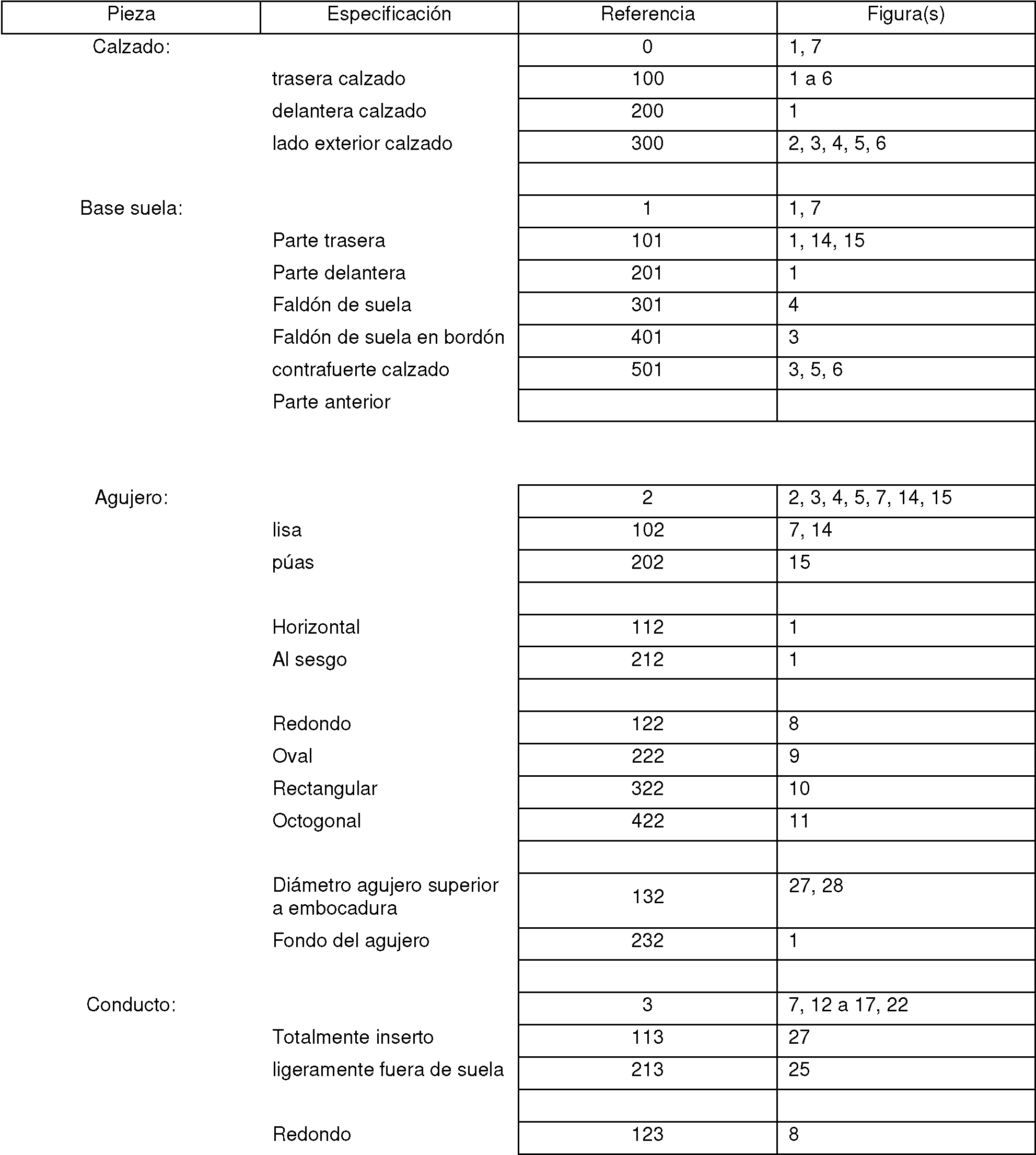

OvalOval
RectangularRectangular
OctogonalOctagonal
Acabado exterior del conductoDuct exterior finish
LisaLisa
asperezasroughness
púasspikes
4 elementos puntiagudos4 pointed elements
Interior totalmente liso Interior con paso de rosca en extremoCompletely smooth interior Interior with thread pitch at the end
paso de rosca en el exterior en extremo extremo ranurasthread pitch on the outside at end end grooves
Embocadura conducto Duct mouth
Diámetro conductoDuct diameter
Parte obstruida del conductoBlocked part of the duct
Tapa:Top:
Base de la tapaLid base
Reborde de la tapaLid flange
Hojuelas tóricasToric flakes
Paso de rosca exterior Paso de rosca interior Agarre tapaExternal thread pitch Internal thread pitch Cap grip
RedondaRound
OvalOval
RectangularRectangular
OctogonalOctagonal
sistema cierre por palanca pasador plaqueta base inferior palanca cabeza de barra

La presente invención no queda en ningún caso limitada al modo de realización descrito a título de ejemplo y representado en las figuras.The present invention is in no way limited to the embodiment described by way of example and represented in the figures.
La presente invención se ha descrito en relación con formas de realización específicas, que tienen un valor puramente ilustrativo y no deben considerarse como limitativas. Los números de referencia en las reivindicaciones no limitan su alcance. The present invention has been described in connection with specific embodiments, which are purely illustrative and should not be construed as limiting. Reference numbers in the claims do not limit their scope.
Claims (22)
Applications Claiming Priority (2)
| Application Number | Priority Date | Filing Date | Title |
|---|---|---|---|
| LU93088A LU93088B1 (en) | 2016-05-30 | 2016-05-30 | Footwear comprising a device with an information or object storage tube |
| PCT/EP2016/071213 WO2017207073A1 (en) | 2016-05-30 | 2016-09-08 | Footwear item comprising a device including a tube for storing information or an object |
Publications (1)
| Publication Number | Publication Date |
|---|---|
| ES2821955T3 true ES2821955T3 (en) | 2021-04-28 |
Family
ID=56292790
Family Applications (1)
| Application Number | Title | Priority Date | Filing Date |
|---|---|---|---|
| ES16763034T Active ES2821955T3 (en) | 2016-05-30 | 2016-09-08 | Footwear comprising a device with an information or object storage tube |
Country Status (14)
| Country | Link |
|---|---|
| US (1) | US20210093037A1 (en) |
| EP (1) | EP3462960B1 (en) |
| JP (1) | JP6902054B2 (en) |
| KR (1) | KR20190032301A (en) |
| CN (1) | CN109414089B (en) |
| AU (1) | AU2016409297B2 (en) |
| BR (1) | BR112018074954B1 (en) |
| CA (1) | CA3025676A1 (en) |
| ES (1) | ES2821955T3 (en) |
| LU (1) | LU93088B1 (en) |
| MX (1) | MX2018014614A (en) |
| PL (1) | PL3462960T3 (en) |
| RU (1) | RU2709161C1 (en) |
| WO (1) | WO2017207073A1 (en) |
Family Cites Families (31)
| Publication number | Priority date | Publication date | Assignee | Title |
|---|---|---|---|---|
| US1751069A (en) * | 1927-02-19 | 1930-03-18 | Blain Albert | Footwear |
| US2507991A (en) * | 1947-07-24 | 1950-05-16 | Thomas E Neal | Wedgie type shoe |
| US2478411A (en) * | 1947-12-01 | 1949-08-09 | Ruby M Martin | Shoe |
| US2904901A (en) * | 1959-01-14 | 1959-09-22 | Goldstein Murray | Receptacle heels for footwear |
| DE3014745A1 (en) * | 1980-04-17 | 1981-10-22 | Itw-Ateco Gmbh, 2000 Norderstedt | ONE-PIECE FASTENING ELEMENT FROM PLASTIC (SELF-CENTERING TREE CLIP) |
| US4724628A (en) * | 1986-01-03 | 1988-02-16 | Schreiner Kevin E | Heel jewelry |
| US5921003A (en) * | 1996-11-18 | 1999-07-13 | Kim; Insop | Shoe with replaceable hygienic cartridge |
| US6094844A (en) * | 1998-10-13 | 2000-08-01 | Potts; Matthew K. | Shoe pocket and method of use |
| US5996261A (en) * | 1999-02-18 | 1999-12-07 | Nelson; Mary K. | Article of footwear having a storage facility |
| US6050007A (en) * | 1999-05-11 | 2000-04-18 | Angelieri; Robert S. | Lighted athletic shoe method and apparatus |
| GB2350279A (en) * | 1999-05-24 | 2000-11-29 | Internet World Sport | Footwear with solid or gel medicament |
| US6289612B1 (en) * | 2000-01-21 | 2001-09-18 | Dorene Jean Kent | Footwear having concealed storage cavity for personal items |
| US6243974B1 (en) * | 2000-06-23 | 2001-06-12 | Patrick N. Schaj | Sandal having compartments therein |
| US6360779B1 (en) * | 2001-04-11 | 2002-03-26 | Aqueduct Utility Pipe Contractor, Inc. | Closure device for a pipe/wall aperture |
| KR100423671B1 (en) * | 2001-06-16 | 2004-03-18 | 이응도 | An Apparatus for Inserting a Recording Paper |
| US6898875B2 (en) * | 2003-07-24 | 2005-05-31 | Kidsational, Inc. | Shoe with drawer |
| US20070199209A1 (en) * | 2006-01-17 | 2007-08-30 | Jennifer Schreck | Shoe with an integrated storage module |
| US7726046B2 (en) * | 2008-04-04 | 2010-06-01 | Kara Portnell | Clock sandal |
| US20100095555A1 (en) * | 2008-10-16 | 2010-04-22 | Combs Jeffrey S | Footware having integral compartment in sole for carrying items |
| CZ2009297A3 (en) * | 2009-05-14 | 2010-11-24 | Zeman@Libor | Protective footwear against effects of contact mines with optimized structural components |
| RU92770U1 (en) * | 2009-12-23 | 2010-04-10 | Закрытое акционерное общество "ФПГ ЭНЕРГОКОНТРАКТ" | BOOT |
| US8544196B2 (en) * | 2010-08-20 | 2013-10-01 | Susan Leo | Shoe charm holder device |
| KR20120130396A (en) * | 2011-05-23 | 2012-12-03 | 박태원 | Weight shoes |
| JP4892644B1 (en) * | 2011-10-31 | 2012-03-07 | 有限会社イズミ産業 | Women's shoe heel fixing structure |
| CN203028218U (en) * | 2013-01-21 | 2013-07-03 | 黄博 | Sounding shoe |
| JP3183540U (en) * | 2013-03-05 | 2013-05-23 | 株式会社コマリヨー | Weight adjustable shoes |
| US9314064B2 (en) * | 2013-12-04 | 2016-04-19 | Schawbel Technologies Llc | Heated insole with removable heating assembly |
| CN203692654U (en) * | 2013-12-04 | 2014-07-09 | 林庆隆 | Storage shoes |
| US9339077B2 (en) * | 2013-12-12 | 2016-05-17 | Ashley Shuman | Integral storage chamber for footwear |
| CN204015280U (en) * | 2014-07-22 | 2014-12-17 | 台州市万利泰鞋业有限公司 | Shoes |
| LU93087B1 (en) * | 2016-05-30 | 2017-12-01 | Global Secure Sa | Footwear comprising an information or object storage device |
-
2016
- 2016-05-30 LU LU93088A patent/LU93088B1/en active IP Right Grant
- 2016-09-08 EP EP16763034.2A patent/EP3462960B1/en active Active
- 2016-09-08 BR BR112018074954-0A patent/BR112018074954B1/en active IP Right Grant
- 2016-09-08 JP JP2018562961A patent/JP6902054B2/en active Active
- 2016-09-08 PL PL16763034T patent/PL3462960T3/en unknown
- 2016-09-08 US US16/306,428 patent/US20210093037A1/en active Pending
- 2016-09-08 KR KR1020187038080A patent/KR20190032301A/en not_active Application Discontinuation
- 2016-09-08 AU AU2016409297A patent/AU2016409297B2/en not_active Ceased
- 2016-09-08 WO PCT/EP2016/071213 patent/WO2017207073A1/en active Search and Examination
- 2016-09-08 ES ES16763034T patent/ES2821955T3/en active Active
- 2016-09-08 CN CN201680086342.7A patent/CN109414089B/en active Active
- 2016-09-08 RU RU2018147076A patent/RU2709161C1/en active
- 2016-09-08 CA CA3025676A patent/CA3025676A1/en active Pending
- 2016-09-08 MX MX2018014614A patent/MX2018014614A/en unknown
Also Published As
| Publication number | Publication date |
|---|---|
| MX2018014614A (en) | 2019-05-22 |
| EP3462960A1 (en) | 2019-04-10 |
| AU2016409297B2 (en) | 2022-08-18 |
| JP6902054B2 (en) | 2021-07-14 |
| CA3025676A1 (en) | 2017-12-07 |
| BR112018074954A2 (en) | 2019-03-12 |
| RU2709161C1 (en) | 2019-12-16 |
| LU93088B1 (en) | 2017-12-01 |
| WO2017207073A1 (en) | 2017-12-07 |
| CN109414089B (en) | 2021-10-22 |
| JP2019517313A (en) | 2019-06-24 |
| AU2016409297A1 (en) | 2018-12-20 |
| KR20190032301A (en) | 2019-03-27 |
| EP3462960B1 (en) | 2020-07-08 |
| US20210093037A1 (en) | 2021-04-01 |
| BR112018074954B1 (en) | 2021-10-19 |
| PL3462960T3 (en) | 2021-02-08 |
| CN109414089A (en) | 2019-03-01 |
Similar Documents
| Publication | Publication Date | Title |
|---|---|---|
| ES2209146T3 (en) | PHARMACEUTICAL CONTAINER OR INHALING DEVICE. | |
| ES2258784T3 (en) | CONTAINER FOR THE ELIMINATION OF MEDICAL WASTE. | |
| ES2748800T3 (en) | Accessory for a syringe or cartridge | |
| ES2414480T3 (en) | Shoe with opening in the heel area so that it can be put easily and adjustable | |
| ES2254221T3 (en) | DEVICE TO ENTER A TAMPON. | |
| ES1068403U (en) | Protection case for video game console (Machine-translation by Google Translate, not legally binding) | |
| US9339077B2 (en) | Integral storage chamber for footwear | |
| ES2821955T3 (en) | Footwear comprising a device with an information or object storage tube | |
| ES2823277T3 (en) | Shoe comprising an information or object storage device | |
| US20190246774A1 (en) | Footwear Transportation Device | |
| ES2256589T3 (en) | CLOSURE FOR CONTAINERS. | |
| ES2280937T3 (en) | SUPPORT FOR PORRA. | |
| JP2019517314A5 (en) | ||
| ES2299708T3 (en) | ORAL ADMINISTRATION FORM OF ACTIVE SUBSTANCES, VITAMINS AND / OR NUTRITIVE SUBSTANCES. | |
| ES2613903B1 (en) | Footwear with sole or heel compartment | |
| ES1219685U (en) | MULTIFUNCTIONAL CONTAINER FOR ICE CREAM (Machine-translation by Google Translate, not legally binding) | |
| Forns-Broggi | Coronación | |
| ES1063845U (en) | Coffee porta-objects, estank and anti-theft (Machine-translation by Google Translate, not legally binding) | |
| TWM456110U (en) | Shoes |