ES2809452T3 - Absorbent layered structure with wicking effect - Google Patents
Absorbent layered structure with wicking effect Download PDFInfo
- Publication number
- ES2809452T3 ES2809452T3 ES15789298T ES15789298T ES2809452T3 ES 2809452 T3 ES2809452 T3 ES 2809452T3 ES 15789298 T ES15789298 T ES 15789298T ES 15789298 T ES15789298 T ES 15789298T ES 2809452 T3 ES2809452 T3 ES 2809452T3
- Authority
- ES
- Spain
- Prior art keywords
- sap
- absorption layer
- bonded
- layer
- core
- Prior art date
- Legal status (The legal status is an assumption and is not a legal conclusion. Google has not performed a legal analysis and makes no representation as to the accuracy of the status listed.)
- Active
Links
- 230000002745 absorbent Effects 0.000 title claims abstract description 51
- 239000002250 absorbent Substances 0.000 title claims abstract description 51
- 230000000694 effects Effects 0.000 title description 5
- 238000010521 absorption reaction Methods 0.000 claims abstract description 120
- 229920000247 superabsorbent polymer Polymers 0.000 claims abstract description 97
- 239000000463 material Substances 0.000 claims abstract description 81
- 239000007788 liquid Substances 0.000 claims abstract description 63
- 239000000835 fiber Substances 0.000 claims abstract description 40
- 238000003860 storage Methods 0.000 claims abstract description 32
- 239000004744 fabric Substances 0.000 claims abstract description 24
- 229910052739 hydrogen Inorganic materials 0.000 claims abstract description 23
- 239000001257 hydrogen Substances 0.000 claims abstract description 23
- 239000004831 Hot glue Substances 0.000 claims abstract description 17
- 238000012546 transfer Methods 0.000 claims abstract description 17
- 125000004435 hydrogen atom Chemical group [H]* 0.000 claims abstract description 16
- 239000011159 matrix material Substances 0.000 claims abstract description 9
- 239000002657 fibrous material Substances 0.000 claims abstract description 4
- 239000012530 fluid Substances 0.000 claims description 20
- 230000032798 delamination Effects 0.000 claims description 12
- 229920001131 Pulp (paper) Polymers 0.000 claims description 7
- 230000001629 suppression Effects 0.000 claims description 3
- 239000011162 core material Substances 0.000 description 42
- 230000001070 adhesive effect Effects 0.000 description 33
- 239000000853 adhesive Substances 0.000 description 32
- 239000000203 mixture Substances 0.000 description 28
- 239000000758 substrate Substances 0.000 description 26
- 229920001169 thermoplastic Polymers 0.000 description 16
- 239000004416 thermosoftening plastic Substances 0.000 description 16
- 238000000034 method Methods 0.000 description 15
- 239000000523 sample Substances 0.000 description 14
- 239000012943 hotmelt Substances 0.000 description 10
- 239000002245 particle Substances 0.000 description 10
- 230000008569 process Effects 0.000 description 10
- 238000002474 experimental method Methods 0.000 description 9
- 238000001035 drying Methods 0.000 description 8
- 239000004745 nonwoven fabric Substances 0.000 description 6
- 239000000047 product Substances 0.000 description 6
- 230000008901 benefit Effects 0.000 description 5
- 238000000151 deposition Methods 0.000 description 5
- 239000003292 glue Substances 0.000 description 5
- 239000000123 paper Substances 0.000 description 5
- 238000012360 testing method Methods 0.000 description 5
- 230000008021 deposition Effects 0.000 description 4
- 238000011067 equilibration Methods 0.000 description 4
- 229920000642 polymer Polymers 0.000 description 4
- 230000009471 action Effects 0.000 description 3
- 238000005516 engineering process Methods 0.000 description 3
- 239000002655 kraft paper Substances 0.000 description 3
- 230000014759 maintenance of location Effects 0.000 description 3
- 238000004519 manufacturing process Methods 0.000 description 3
- VSKJLJHPAFKHBX-UHFFFAOYSA-N 2-methylbuta-1,3-diene;styrene Chemical compound CC(=C)C=C.C=CC1=CC=CC=C1.C=CC1=CC=CC=C1 VSKJLJHPAFKHBX-UHFFFAOYSA-N 0.000 description 2
- 229920003043 Cellulose fiber Polymers 0.000 description 2
- VYPSYNLAJGMNEJ-UHFFFAOYSA-N Silicium dioxide Chemical compound O=[Si]=O VYPSYNLAJGMNEJ-UHFFFAOYSA-N 0.000 description 2
- FAPWRFPIFSIZLT-UHFFFAOYSA-M Sodium chloride Chemical compound [Na+].[Cl-] FAPWRFPIFSIZLT-UHFFFAOYSA-M 0.000 description 2
- 229920002472 Starch Polymers 0.000 description 2
- -1 alkali metal salts Chemical class 0.000 description 2
- FACXGONDLDSNOE-UHFFFAOYSA-N buta-1,3-diene;styrene Chemical compound C=CC=C.C=CC1=CC=CC=C1.C=CC1=CC=CC=C1 FACXGONDLDSNOE-UHFFFAOYSA-N 0.000 description 2
- 229920001577 copolymer Polymers 0.000 description 2
- 230000003993 interaction Effects 0.000 description 2
- 238000003475 lamination Methods 0.000 description 2
- 239000011368 organic material Substances 0.000 description 2
- 230000035699 permeability Effects 0.000 description 2
- 229920002401 polyacrylamide Polymers 0.000 description 2
- 229920000058 polyacrylate Polymers 0.000 description 2
- 230000009467 reduction Effects 0.000 description 2
- 239000004627 regenerated cellulose Substances 0.000 description 2
- 230000000717 retained effect Effects 0.000 description 2
- 238000000926 separation method Methods 0.000 description 2
- 238000007493 shaping process Methods 0.000 description 2
- 239000011122 softwood Substances 0.000 description 2
- 239000008107 starch Substances 0.000 description 2
- 235000019698 starch Nutrition 0.000 description 2
- 229920000468 styrene butadiene styrene block copolymer Polymers 0.000 description 2
- 230000008961 swelling Effects 0.000 description 2
- 229920003051 synthetic elastomer Polymers 0.000 description 2
- 239000005061 synthetic rubber Substances 0.000 description 2
- 238000009736 wetting Methods 0.000 description 2
- SMZOUWXMTYCWNB-UHFFFAOYSA-N 2-(2-methoxy-5-methylphenyl)ethanamine Chemical compound COC1=CC=C(C)C=C1CCN SMZOUWXMTYCWNB-UHFFFAOYSA-N 0.000 description 1
- NIXOWILDQLNWCW-UHFFFAOYSA-N 2-Propenoic acid Natural products OC(=O)C=C NIXOWILDQLNWCW-UHFFFAOYSA-N 0.000 description 1
- NLHHRLWOUZZQLW-UHFFFAOYSA-N Acrylonitrile Chemical compound C=CC#N NLHHRLWOUZZQLW-UHFFFAOYSA-N 0.000 description 1
- 229920001817 Agar Polymers 0.000 description 1
- 238000012935 Averaging Methods 0.000 description 1
- 229920002134 Carboxymethyl cellulose Polymers 0.000 description 1
- 229920000742 Cotton Polymers 0.000 description 1
- 229920002907 Guar gum Polymers 0.000 description 1
- 229920002153 Hydroxypropyl cellulose Polymers 0.000 description 1
- 206010021639 Incontinence Diseases 0.000 description 1
- 240000006240 Linum usitatissimum Species 0.000 description 1
- 235000004431 Linum usitatissimum Nutrition 0.000 description 1
- 235000008331 Pinus X rigitaeda Nutrition 0.000 description 1
- 235000011613 Pinus brutia Nutrition 0.000 description 1
- 241000018646 Pinus brutia Species 0.000 description 1
- 235000005018 Pinus echinata Nutrition 0.000 description 1
- 241001236219 Pinus echinata Species 0.000 description 1
- 235000017339 Pinus palustris Nutrition 0.000 description 1
- 239000004743 Polypropylene Substances 0.000 description 1
- 239000004820 Pressure-sensitive adhesive Substances 0.000 description 1
- 229920000297 Rayon Polymers 0.000 description 1
- 229920002125 Sokalan® Polymers 0.000 description 1
- 229910000831 Steel Inorganic materials 0.000 description 1
- LSNNMFCWUKXFEE-UHFFFAOYSA-N Sulfurous acid Chemical compound OS(O)=O LSNNMFCWUKXFEE-UHFFFAOYSA-N 0.000 description 1
- 239000006096 absorbing agent Substances 0.000 description 1
- 239000000654 additive Substances 0.000 description 1
- 239000004840 adhesive resin Substances 0.000 description 1
- 229920006223 adhesive resin Polymers 0.000 description 1
- 230000002411 adverse Effects 0.000 description 1
- 239000008272 agar Substances 0.000 description 1
- 235000010419 agar Nutrition 0.000 description 1
- 229910052783 alkali metal Inorganic materials 0.000 description 1
- 238000004458 analytical method Methods 0.000 description 1
- 239000003963 antioxidant agent Substances 0.000 description 1
- 239000002585 base Substances 0.000 description 1
- 239000011230 binding agent Substances 0.000 description 1
- 229920001400 block copolymer Polymers 0.000 description 1
- 239000001768 carboxy methyl cellulose Substances 0.000 description 1
- 235000010948 carboxy methyl cellulose Nutrition 0.000 description 1
- 239000008112 carboxymethyl-cellulose Substances 0.000 description 1
- 238000005253 cladding Methods 0.000 description 1
- 230000000295 complement effect Effects 0.000 description 1
- 230000006835 compression Effects 0.000 description 1
- 238000007906 compression Methods 0.000 description 1
- 239000000470 constituent Substances 0.000 description 1
- 229920006037 cross link polymer Polymers 0.000 description 1
- 230000003247 decreasing effect Effects 0.000 description 1
- 230000007812 deficiency Effects 0.000 description 1
- 230000001419 dependent effect Effects 0.000 description 1
- 238000005137 deposition process Methods 0.000 description 1
- 230000001066 destructive effect Effects 0.000 description 1
- 238000010586 diagram Methods 0.000 description 1
- 238000009792 diffusion process Methods 0.000 description 1
- 239000006185 dispersion Substances 0.000 description 1
- 238000009826 distribution Methods 0.000 description 1
- 238000004049 embossing Methods 0.000 description 1
- 238000011156 evaluation Methods 0.000 description 1
- 239000006260 foam Substances 0.000 description 1
- 239000000499 gel Substances 0.000 description 1
- 239000000665 guar gum Substances 0.000 description 1
- 229960002154 guar gum Drugs 0.000 description 1
- 235000010417 guar gum Nutrition 0.000 description 1
- 239000011121 hardwood Substances 0.000 description 1
- 230000000887 hydrating effect Effects 0.000 description 1
- 239000001863 hydroxypropyl cellulose Substances 0.000 description 1
- 235000010977 hydroxypropyl cellulose Nutrition 0.000 description 1
- 230000006872 improvement Effects 0.000 description 1
- 239000012535 impurity Substances 0.000 description 1
- 239000004615 ingredient Substances 0.000 description 1
- 229910010272 inorganic material Inorganic materials 0.000 description 1
- 239000011147 inorganic material Substances 0.000 description 1
- 238000005304 joining Methods 0.000 description 1
- VSEAAEQOQBMPQF-UHFFFAOYSA-N morpholin-3-one Chemical compound O=C1COCCN1 VSEAAEQOQBMPQF-UHFFFAOYSA-N 0.000 description 1
- 150000002894 organic compounds Chemical class 0.000 description 1
- 239000003960 organic solvent Substances 0.000 description 1
- 239000003415 peat Substances 0.000 description 1
- 239000001814 pectin Substances 0.000 description 1
- 235000010987 pectin Nutrition 0.000 description 1
- 229920001277 pectin Polymers 0.000 description 1
- 239000004014 plasticizer Substances 0.000 description 1
- 229920001155 polypropylene Polymers 0.000 description 1
- 229920001289 polyvinyl ether Polymers 0.000 description 1
- 229920002717 polyvinylpyridine Polymers 0.000 description 1
- 239000011148 porous material Substances 0.000 description 1
- 239000000843 powder Substances 0.000 description 1
- 238000012545 processing Methods 0.000 description 1
- 239000000377 silicon dioxide Substances 0.000 description 1
- 239000002195 soluble material Substances 0.000 description 1
- 238000001179 sorption measurement Methods 0.000 description 1
- 241000894007 species Species 0.000 description 1
- 239000007921 spray Substances 0.000 description 1
- 239000003381 stabilizer Substances 0.000 description 1
- 230000000087 stabilizing effect Effects 0.000 description 1
- 239000010959 steel Substances 0.000 description 1
- 239000013589 supplement Substances 0.000 description 1
- 229920002994 synthetic fiber Polymers 0.000 description 1
- 239000012209 synthetic fiber Substances 0.000 description 1
- 238000010998 test method Methods 0.000 description 1
- 238000009827 uniform distribution Methods 0.000 description 1
- 210000002700 urine Anatomy 0.000 description 1
- 229920002554 vinyl polymer Polymers 0.000 description 1
- NLVXSWCKKBEXTG-UHFFFAOYSA-N vinylsulfonic acid Chemical compound OS(=O)(=O)C=C NLVXSWCKKBEXTG-UHFFFAOYSA-N 0.000 description 1
- 239000001993 wax Substances 0.000 description 1
- 238000005303 weighing Methods 0.000 description 1
- 239000002759 woven fabric Substances 0.000 description 1
Classifications
-
- A—HUMAN NECESSITIES
- A61—MEDICAL OR VETERINARY SCIENCE; HYGIENE
- A61F—FILTERS IMPLANTABLE INTO BLOOD VESSELS; PROSTHESES; DEVICES PROVIDING PATENCY TO, OR PREVENTING COLLAPSING OF, TUBULAR STRUCTURES OF THE BODY, e.g. STENTS; ORTHOPAEDIC, NURSING OR CONTRACEPTIVE DEVICES; FOMENTATION; TREATMENT OR PROTECTION OF EYES OR EARS; BANDAGES, DRESSINGS OR ABSORBENT PADS; FIRST-AID KITS
- A61F13/00—Bandages or dressings; Absorbent pads
- A61F13/15—Absorbent pads, e.g. sanitary towels, swabs or tampons for external or internal application to the body; Supporting or fastening means therefor; Tampon applicators
- A61F13/53—Absorbent pads, e.g. sanitary towels, swabs or tampons for external or internal application to the body; Supporting or fastening means therefor; Tampon applicators characterised by the absorbing medium
- A61F13/534—Absorbent pads, e.g. sanitary towels, swabs or tampons for external or internal application to the body; Supporting or fastening means therefor; Tampon applicators characterised by the absorbing medium having an inhomogeneous composition through the thickness of the pad
- A61F13/537—Absorbent pads, e.g. sanitary towels, swabs or tampons for external or internal application to the body; Supporting or fastening means therefor; Tampon applicators characterised by the absorbing medium having an inhomogeneous composition through the thickness of the pad characterised by a layer facilitating or inhibiting flow in one direction or plane, e.g. a wicking layer
-
- A—HUMAN NECESSITIES
- A61—MEDICAL OR VETERINARY SCIENCE; HYGIENE
- A61F—FILTERS IMPLANTABLE INTO BLOOD VESSELS; PROSTHESES; DEVICES PROVIDING PATENCY TO, OR PREVENTING COLLAPSING OF, TUBULAR STRUCTURES OF THE BODY, e.g. STENTS; ORTHOPAEDIC, NURSING OR CONTRACEPTIVE DEVICES; FOMENTATION; TREATMENT OR PROTECTION OF EYES OR EARS; BANDAGES, DRESSINGS OR ABSORBENT PADS; FIRST-AID KITS
- A61F13/00—Bandages or dressings; Absorbent pads
- A61F13/15—Absorbent pads, e.g. sanitary towels, swabs or tampons for external or internal application to the body; Supporting or fastening means therefor; Tampon applicators
- A61F13/15577—Apparatus or processes for manufacturing
- A61F13/15707—Mechanical treatment, e.g. notching, twisting, compressing, shaping
-
- A—HUMAN NECESSITIES
- A61—MEDICAL OR VETERINARY SCIENCE; HYGIENE
- A61F—FILTERS IMPLANTABLE INTO BLOOD VESSELS; PROSTHESES; DEVICES PROVIDING PATENCY TO, OR PREVENTING COLLAPSING OF, TUBULAR STRUCTURES OF THE BODY, e.g. STENTS; ORTHOPAEDIC, NURSING OR CONTRACEPTIVE DEVICES; FOMENTATION; TREATMENT OR PROTECTION OF EYES OR EARS; BANDAGES, DRESSINGS OR ABSORBENT PADS; FIRST-AID KITS
- A61F13/00—Bandages or dressings; Absorbent pads
- A61F13/15—Absorbent pads, e.g. sanitary towels, swabs or tampons for external or internal application to the body; Supporting or fastening means therefor; Tampon applicators
- A61F13/53—Absorbent pads, e.g. sanitary towels, swabs or tampons for external or internal application to the body; Supporting or fastening means therefor; Tampon applicators characterised by the absorbing medium
- A61F13/534—Absorbent pads, e.g. sanitary towels, swabs or tampons for external or internal application to the body; Supporting or fastening means therefor; Tampon applicators characterised by the absorbing medium having an inhomogeneous composition through the thickness of the pad
-
- B—PERFORMING OPERATIONS; TRANSPORTING
- B32—LAYERED PRODUCTS
- B32B—LAYERED PRODUCTS, i.e. PRODUCTS BUILT-UP OF STRATA OF FLAT OR NON-FLAT, e.g. CELLULAR OR HONEYCOMB, FORM
- B32B5/00—Layered products characterised by the non- homogeneity or physical structure, i.e. comprising a fibrous, filamentary, particulate or foam layer; Layered products characterised by having a layer differing constitutionally or physically in different parts
- B32B5/02—Layered products characterised by the non- homogeneity or physical structure, i.e. comprising a fibrous, filamentary, particulate or foam layer; Layered products characterised by having a layer differing constitutionally or physically in different parts characterised by structural features of a fibrous or filamentary layer
- B32B5/022—Non-woven fabric
-
- B—PERFORMING OPERATIONS; TRANSPORTING
- B32—LAYERED PRODUCTS
- B32B—LAYERED PRODUCTS, i.e. PRODUCTS BUILT-UP OF STRATA OF FLAT OR NON-FLAT, e.g. CELLULAR OR HONEYCOMB, FORM
- B32B5/00—Layered products characterised by the non- homogeneity or physical structure, i.e. comprising a fibrous, filamentary, particulate or foam layer; Layered products characterised by having a layer differing constitutionally or physically in different parts
- B32B5/02—Layered products characterised by the non- homogeneity or physical structure, i.e. comprising a fibrous, filamentary, particulate or foam layer; Layered products characterised by having a layer differing constitutionally or physically in different parts characterised by structural features of a fibrous or filamentary layer
- B32B5/08—Layered products characterised by the non- homogeneity or physical structure, i.e. comprising a fibrous, filamentary, particulate or foam layer; Layered products characterised by having a layer differing constitutionally or physically in different parts characterised by structural features of a fibrous or filamentary layer the fibres or filaments of a layer being of different substances, e.g. conjugate fibres, mixture of different fibres
-
- B—PERFORMING OPERATIONS; TRANSPORTING
- B32—LAYERED PRODUCTS
- B32B—LAYERED PRODUCTS, i.e. PRODUCTS BUILT-UP OF STRATA OF FLAT OR NON-FLAT, e.g. CELLULAR OR HONEYCOMB, FORM
- B32B5/00—Layered products characterised by the non- homogeneity or physical structure, i.e. comprising a fibrous, filamentary, particulate or foam layer; Layered products characterised by having a layer differing constitutionally or physically in different parts
- B32B5/22—Layered products characterised by the non- homogeneity or physical structure, i.e. comprising a fibrous, filamentary, particulate or foam layer; Layered products characterised by having a layer differing constitutionally or physically in different parts characterised by the presence of two or more layers which are next to each other and are fibrous, filamentary, formed of particles or foamed
- B32B5/24—Layered products characterised by the non- homogeneity or physical structure, i.e. comprising a fibrous, filamentary, particulate or foam layer; Layered products characterised by having a layer differing constitutionally or physically in different parts characterised by the presence of two or more layers which are next to each other and are fibrous, filamentary, formed of particles or foamed one layer being a fibrous or filamentary layer
- B32B5/26—Layered products characterised by the non- homogeneity or physical structure, i.e. comprising a fibrous, filamentary, particulate or foam layer; Layered products characterised by having a layer differing constitutionally or physically in different parts characterised by the presence of two or more layers which are next to each other and are fibrous, filamentary, formed of particles or foamed one layer being a fibrous or filamentary layer another layer next to it also being fibrous or filamentary
-
- B—PERFORMING OPERATIONS; TRANSPORTING
- B32—LAYERED PRODUCTS
- B32B—LAYERED PRODUCTS, i.e. PRODUCTS BUILT-UP OF STRATA OF FLAT OR NON-FLAT, e.g. CELLULAR OR HONEYCOMB, FORM
- B32B7/00—Layered products characterised by the relation between layers; Layered products characterised by the relative orientation of features between layers, or by the relative values of a measurable parameter between layers, i.e. products comprising layers having different physical, chemical or physicochemical properties; Layered products characterised by the interconnection of layers
- B32B7/04—Interconnection of layers
- B32B7/12—Interconnection of layers using interposed adhesives or interposed materials with bonding properties
-
- A—HUMAN NECESSITIES
- A61—MEDICAL OR VETERINARY SCIENCE; HYGIENE
- A61F—FILTERS IMPLANTABLE INTO BLOOD VESSELS; PROSTHESES; DEVICES PROVIDING PATENCY TO, OR PREVENTING COLLAPSING OF, TUBULAR STRUCTURES OF THE BODY, e.g. STENTS; ORTHOPAEDIC, NURSING OR CONTRACEPTIVE DEVICES; FOMENTATION; TREATMENT OR PROTECTION OF EYES OR EARS; BANDAGES, DRESSINGS OR ABSORBENT PADS; FIRST-AID KITS
- A61F13/00—Bandages or dressings; Absorbent pads
- A61F13/15—Absorbent pads, e.g. sanitary towels, swabs or tampons for external or internal application to the body; Supporting or fastening means therefor; Tampon applicators
- A61F13/53—Absorbent pads, e.g. sanitary towels, swabs or tampons for external or internal application to the body; Supporting or fastening means therefor; Tampon applicators characterised by the absorbing medium
- A61F2013/530131—Absorbent pads, e.g. sanitary towels, swabs or tampons for external or internal application to the body; Supporting or fastening means therefor; Tampon applicators characterised by the absorbing medium being made in fibre but being not pulp
- A61F2013/530343—Absorbent pads, e.g. sanitary towels, swabs or tampons for external or internal application to the body; Supporting or fastening means therefor; Tampon applicators characterised by the absorbing medium being made in fibre but being not pulp being natural fibres
-
- A—HUMAN NECESSITIES
- A61—MEDICAL OR VETERINARY SCIENCE; HYGIENE
- A61F—FILTERS IMPLANTABLE INTO BLOOD VESSELS; PROSTHESES; DEVICES PROVIDING PATENCY TO, OR PREVENTING COLLAPSING OF, TUBULAR STRUCTURES OF THE BODY, e.g. STENTS; ORTHOPAEDIC, NURSING OR CONTRACEPTIVE DEVICES; FOMENTATION; TREATMENT OR PROTECTION OF EYES OR EARS; BANDAGES, DRESSINGS OR ABSORBENT PADS; FIRST-AID KITS
- A61F13/00—Bandages or dressings; Absorbent pads
- A61F13/15—Absorbent pads, e.g. sanitary towels, swabs or tampons for external or internal application to the body; Supporting or fastening means therefor; Tampon applicators
- A61F13/53—Absorbent pads, e.g. sanitary towels, swabs or tampons for external or internal application to the body; Supporting or fastening means therefor; Tampon applicators characterised by the absorbing medium
- A61F2013/530481—Absorbent pads, e.g. sanitary towels, swabs or tampons for external or internal application to the body; Supporting or fastening means therefor; Tampon applicators characterised by the absorbing medium having superabsorbent materials, i.e. highly absorbent polymer gel materials
-
- A—HUMAN NECESSITIES
- A61—MEDICAL OR VETERINARY SCIENCE; HYGIENE
- A61F—FILTERS IMPLANTABLE INTO BLOOD VESSELS; PROSTHESES; DEVICES PROVIDING PATENCY TO, OR PREVENTING COLLAPSING OF, TUBULAR STRUCTURES OF THE BODY, e.g. STENTS; ORTHOPAEDIC, NURSING OR CONTRACEPTIVE DEVICES; FOMENTATION; TREATMENT OR PROTECTION OF EYES OR EARS; BANDAGES, DRESSINGS OR ABSORBENT PADS; FIRST-AID KITS
- A61F13/00—Bandages or dressings; Absorbent pads
- A61F13/15—Absorbent pads, e.g. sanitary towels, swabs or tampons for external or internal application to the body; Supporting or fastening means therefor; Tampon applicators
- A61F13/53—Absorbent pads, e.g. sanitary towels, swabs or tampons for external or internal application to the body; Supporting or fastening means therefor; Tampon applicators characterised by the absorbing medium
- A61F13/534—Absorbent pads, e.g. sanitary towels, swabs or tampons for external or internal application to the body; Supporting or fastening means therefor; Tampon applicators characterised by the absorbing medium having an inhomogeneous composition through the thickness of the pad
- A61F2013/53454—Absorbent pads, e.g. sanitary towels, swabs or tampons for external or internal application to the body; Supporting or fastening means therefor; Tampon applicators characterised by the absorbing medium having an inhomogeneous composition through the thickness of the pad with mirror-like structure
-
- A—HUMAN NECESSITIES
- A61—MEDICAL OR VETERINARY SCIENCE; HYGIENE
- A61F—FILTERS IMPLANTABLE INTO BLOOD VESSELS; PROSTHESES; DEVICES PROVIDING PATENCY TO, OR PREVENTING COLLAPSING OF, TUBULAR STRUCTURES OF THE BODY, e.g. STENTS; ORTHOPAEDIC, NURSING OR CONTRACEPTIVE DEVICES; FOMENTATION; TREATMENT OR PROTECTION OF EYES OR EARS; BANDAGES, DRESSINGS OR ABSORBENT PADS; FIRST-AID KITS
- A61F13/00—Bandages or dressings; Absorbent pads
- A61F13/15—Absorbent pads, e.g. sanitary towels, swabs or tampons for external or internal application to the body; Supporting or fastening means therefor; Tampon applicators
- A61F13/53—Absorbent pads, e.g. sanitary towels, swabs or tampons for external or internal application to the body; Supporting or fastening means therefor; Tampon applicators characterised by the absorbing medium
- A61F13/534—Absorbent pads, e.g. sanitary towels, swabs or tampons for external or internal application to the body; Supporting or fastening means therefor; Tampon applicators characterised by the absorbing medium having an inhomogeneous composition through the thickness of the pad
- A61F13/537—Absorbent pads, e.g. sanitary towels, swabs or tampons for external or internal application to the body; Supporting or fastening means therefor; Tampon applicators characterised by the absorbing medium having an inhomogeneous composition through the thickness of the pad characterised by a layer facilitating or inhibiting flow in one direction or plane, e.g. a wicking layer
- A61F13/53708—Absorbent pads, e.g. sanitary towels, swabs or tampons for external or internal application to the body; Supporting or fastening means therefor; Tampon applicators characterised by the absorbing medium having an inhomogeneous composition through the thickness of the pad characterised by a layer facilitating or inhibiting flow in one direction or plane, e.g. a wicking layer the layer having a promotional function on liquid propagation in at least one direction
- A61F2013/53721—Absorbent pads, e.g. sanitary towels, swabs or tampons for external or internal application to the body; Supporting or fastening means therefor; Tampon applicators characterised by the absorbing medium having an inhomogeneous composition through the thickness of the pad characterised by a layer facilitating or inhibiting flow in one direction or plane, e.g. a wicking layer the layer having a promotional function on liquid propagation in at least one direction with capillary means
- A61F2013/53739—Absorbent pads, e.g. sanitary towels, swabs or tampons for external or internal application to the body; Supporting or fastening means therefor; Tampon applicators characterised by the absorbing medium having an inhomogeneous composition through the thickness of the pad characterised by a layer facilitating or inhibiting flow in one direction or plane, e.g. a wicking layer the layer having a promotional function on liquid propagation in at least one direction with capillary means with compressed points
-
- A—HUMAN NECESSITIES
- A61—MEDICAL OR VETERINARY SCIENCE; HYGIENE
- A61F—FILTERS IMPLANTABLE INTO BLOOD VESSELS; PROSTHESES; DEVICES PROVIDING PATENCY TO, OR PREVENTING COLLAPSING OF, TUBULAR STRUCTURES OF THE BODY, e.g. STENTS; ORTHOPAEDIC, NURSING OR CONTRACEPTIVE DEVICES; FOMENTATION; TREATMENT OR PROTECTION OF EYES OR EARS; BANDAGES, DRESSINGS OR ABSORBENT PADS; FIRST-AID KITS
- A61F13/00—Bandages or dressings; Absorbent pads
- A61F13/15—Absorbent pads, e.g. sanitary towels, swabs or tampons for external or internal application to the body; Supporting or fastening means therefor; Tampon applicators
- A61F13/53—Absorbent pads, e.g. sanitary towels, swabs or tampons for external or internal application to the body; Supporting or fastening means therefor; Tampon applicators characterised by the absorbing medium
- A61F13/539—Absorbent pads, e.g. sanitary towels, swabs or tampons for external or internal application to the body; Supporting or fastening means therefor; Tampon applicators characterised by the absorbing medium characterised by the connection of the absorbent layers with each other or with the outer layers
- A61F2013/53908—Absorbent pads, e.g. sanitary towels, swabs or tampons for external or internal application to the body; Supporting or fastening means therefor; Tampon applicators characterised by the absorbing medium characterised by the connection of the absorbent layers with each other or with the outer layers with adhesive
- A61F2013/53925—Absorbent pads, e.g. sanitary towels, swabs or tampons for external or internal application to the body; Supporting or fastening means therefor; Tampon applicators characterised by the absorbing medium characterised by the connection of the absorbent layers with each other or with the outer layers with adhesive with intermittent pattern, e.g. spots
-
- A—HUMAN NECESSITIES
- A61—MEDICAL OR VETERINARY SCIENCE; HYGIENE
- A61F—FILTERS IMPLANTABLE INTO BLOOD VESSELS; PROSTHESES; DEVICES PROVIDING PATENCY TO, OR PREVENTING COLLAPSING OF, TUBULAR STRUCTURES OF THE BODY, e.g. STENTS; ORTHOPAEDIC, NURSING OR CONTRACEPTIVE DEVICES; FOMENTATION; TREATMENT OR PROTECTION OF EYES OR EARS; BANDAGES, DRESSINGS OR ABSORBENT PADS; FIRST-AID KITS
- A61F13/00—Bandages or dressings; Absorbent pads
- A61F13/15—Absorbent pads, e.g. sanitary towels, swabs or tampons for external or internal application to the body; Supporting or fastening means therefor; Tampon applicators
- A61F13/53—Absorbent pads, e.g. sanitary towels, swabs or tampons for external or internal application to the body; Supporting or fastening means therefor; Tampon applicators characterised by the absorbing medium
- A61F13/539—Absorbent pads, e.g. sanitary towels, swabs or tampons for external or internal application to the body; Supporting or fastening means therefor; Tampon applicators characterised by the absorbing medium characterised by the connection of the absorbent layers with each other or with the outer layers
- A61F2013/5395—Absorbent pads, e.g. sanitary towels, swabs or tampons for external or internal application to the body; Supporting or fastening means therefor; Tampon applicators characterised by the absorbing medium characterised by the connection of the absorbent layers with each other or with the outer layers with thermoplastic agent, i.e. softened by heat
-
- B—PERFORMING OPERATIONS; TRANSPORTING
- B32—LAYERED PRODUCTS
- B32B—LAYERED PRODUCTS, i.e. PRODUCTS BUILT-UP OF STRATA OF FLAT OR NON-FLAT, e.g. CELLULAR OR HONEYCOMB, FORM
- B32B2250/00—Layers arrangement
- B32B2250/03—3 layers
-
- B—PERFORMING OPERATIONS; TRANSPORTING
- B32—LAYERED PRODUCTS
- B32B—LAYERED PRODUCTS, i.e. PRODUCTS BUILT-UP OF STRATA OF FLAT OR NON-FLAT, e.g. CELLULAR OR HONEYCOMB, FORM
- B32B2262/00—Composition or structural features of fibres which form a fibrous or filamentary layer or are present as additives
- B32B2262/02—Synthetic macromolecular fibres
- B32B2262/0253—Polyolefin fibres
-
- B—PERFORMING OPERATIONS; TRANSPORTING
- B32—LAYERED PRODUCTS
- B32B—LAYERED PRODUCTS, i.e. PRODUCTS BUILT-UP OF STRATA OF FLAT OR NON-FLAT, e.g. CELLULAR OR HONEYCOMB, FORM
- B32B2307/00—Properties of the layers or laminate
- B32B2307/70—Other properties
- B32B2307/718—Weight, e.g. weight per square meter
-
- B—PERFORMING OPERATIONS; TRANSPORTING
- B32—LAYERED PRODUCTS
- B32B—LAYERED PRODUCTS, i.e. PRODUCTS BUILT-UP OF STRATA OF FLAT OR NON-FLAT, e.g. CELLULAR OR HONEYCOMB, FORM
- B32B2307/00—Properties of the layers or laminate
- B32B2307/70—Other properties
- B32B2307/72—Density
-
- B—PERFORMING OPERATIONS; TRANSPORTING
- B32—LAYERED PRODUCTS
- B32B—LAYERED PRODUCTS, i.e. PRODUCTS BUILT-UP OF STRATA OF FLAT OR NON-FLAT, e.g. CELLULAR OR HONEYCOMB, FORM
- B32B2555/00—Personal care
-
- Y—GENERAL TAGGING OF NEW TECHNOLOGICAL DEVELOPMENTS; GENERAL TAGGING OF CROSS-SECTIONAL TECHNOLOGIES SPANNING OVER SEVERAL SECTIONS OF THE IPC; TECHNICAL SUBJECTS COVERED BY FORMER USPC CROSS-REFERENCE ART COLLECTIONS [XRACs] AND DIGESTS
- Y10—TECHNICAL SUBJECTS COVERED BY FORMER USPC
- Y10T—TECHNICAL SUBJECTS COVERED BY FORMER US CLASSIFICATION
- Y10T156/00—Adhesive bonding and miscellaneous chemical manufacture
- Y10T156/10—Methods of surface bonding and/or assembly therefor
- Y10T156/1002—Methods of surface bonding and/or assembly therefor with permanent bending or reshaping or surface deformation of self sustaining lamina
- Y10T156/1007—Running or continuous length work
- Y10T156/1023—Surface deformation only [e.g., embossing]
Landscapes
- Health & Medical Sciences (AREA)
- Engineering & Computer Science (AREA)
- Vascular Medicine (AREA)
- Epidemiology (AREA)
- Biomedical Technology (AREA)
- Heart & Thoracic Surgery (AREA)
- Life Sciences & Earth Sciences (AREA)
- Animal Behavior & Ethology (AREA)
- General Health & Medical Sciences (AREA)
- Public Health (AREA)
- Veterinary Medicine (AREA)
- Textile Engineering (AREA)
- Mechanical Engineering (AREA)
- Manufacturing & Machinery (AREA)
- Absorbent Articles And Supports Therefor (AREA)
Abstract
Una estructura absorbente en capas, que comprende: una capa de absorción central que comprende material depositado por aire unido por hidrógeno que comprende material fibroso celulósico; y primera y segunda capas de almacenamiento de líquido situadas en relación de transferencia de líquido en lados opuestos respectivos de la capa de absorción central, comprendiendo cada una de la primera y segunda capas de almacenamiento de líquido una matriz de filamentos adhesivos termofusibles y polímero superabsorbente (SAP), en donde los filamentos adhesivos termofusibles están configurados para adherir las primera y segunda capas de almacenamiento a los lados opuestos respectivos de la capa de absorción central, y en donde cada una de la primera y segunda capas de almacenamiento de líquido comprenden una capa de tejido de fibra celulósica adherida a la matriz respectiva de filamentos adhesivos termofusibles y SAP en el lado de la matriz respectiva opuesta a la capa de absorción central.A layered absorbent structure, comprising: a core absorbent layer comprising hydrogen bonded airlaid material comprising cellulosic fibrous material; and first and second liquid storage layers located in liquid transfer relationship on respective opposite sides of the central absorption layer, each of the first and second liquid storage layers comprising a matrix of hot melt adhesive filaments and superabsorbent polymer ( SAP), wherein the hot melt adhesive filaments are configured to adhere the first and second storage layers to respective opposite sides of the central absorption layer, and wherein each of the first and second liquid storage layers comprise a layer of cellulosic fiber fabric adhered to the respective matrix of hot melt adhesive filaments and SAP on the side of the respective matrix opposite the central absorption layer.
Description
DESCRIPCIÓNDESCRIPTION
Estructura absorbente en capas con efecto de absorciónAbsorbent layered structure with wicking effect
Campo de la invenciónField of the invention
La presente invención se refiere a una estructura absorbente en capas que incluye laminados absorbentes que incluyen material superabsorbente en partículas y filamentos adhesivos termofusibles con la estructura absorbente que incluye una capa de absorción que mejora la dispersión del fluido y el rendimiento de rehumectación.The present invention relates to a layered absorbent structure including absorbent laminates including particulate superabsorbent material and hot melt adhesive filaments with the absorbent structure including an absorbent layer that improves fluid dispersion and rewet performance.
Descripción de la técnica relacionadaDescription of Related Art
Los núcleos absorbentes en artículos absorbentes, como pañales desechables, productos para la incontinencia y productos de higiene femenina, se han vuelto progresivamente más finos, con la cantidad de material polimérico superabsorbente (SAP) aumentando, y la cantidad de pulpa de madera y otras fibras generalmente disminuyendo. The absorbent cores in absorbent articles, such as disposable diapers, incontinence products, and feminine hygiene products, have become progressively thinner, with the amount of superabsorbent polymeric material (SAP) increasing, and the amount of wood pulp and other fibers. generally decreasing.
Actualmente, ciertas ofertas de productos comprenden núcleos que incluyen laminados absorbentes finos. Estos laminados comprenden capas de sustrato superior e inferior, hechas de tejido, por ejemplo, con una capa intermedia intercalada entre las capas superior e inferior que comprende partículas de material superabsorbente y normalmente una composición adhesiva termoplástica para garantizar la integridad del laminado.Currently, certain product offerings comprise cores that include fine absorbent laminates. These laminates comprise upper and lower substrate layers, made of fabric, for example, with an intermediate layer sandwiched between the upper and lower layers comprising particles of superabsorbent material and usually a thermoplastic adhesive composition to ensure the integrity of the laminate.
Uno de estos laminados se describe en la publicación de patente de Estados Unidos n.° 2012/0148821, cuya divulgación se incorpora en el presente documento por referencia. Un beneficio principal de este tipo de núcleo laminado es que es extremadamente fino y flexible en relación con su capacidad absorbente. No obstante, se ha observado que este tipo de laminado no se extiende ni absorbe el fluido en las direcciones longitudinal y transversal dentro del núcleo en un grado satisfactorio, causando, como resultado, una utilización reducida del núcleo y un secado menos que satisfactorio del área objetivo del núcleo, como lo indica el denominado rendimiento de rehumectación. One such laminate is described in US Patent Publication No. 2012/0148821, the disclosure of which is incorporated herein by reference. A primary benefit of this type of laminated core is that it is extremely thin and flexible in relation to its absorbent capacity. However, it has been observed that this type of laminate does not extend or absorb fluid in the longitudinal and transverse directions within the core to a satisfactory degree, resulting in reduced core utilization and less than satisfactory area drying. target core, as indicated by so-called rewet performance.
Se ha encontrado que en este tipo de laminado, que reemplazar simplemente una de las capas de sustrato con una capa de absorción, no ha sido satisfactorio. En primer lugar, el material se vuelve "lateral" en el sentido de que la secuencia de capas constituyentes difiere de una cara a la otra. Como consecuencia, puede ser necesario voltear o invertir el laminado a medida que se extrae de un paquete de larga ejecución, como una caja de tejidos ondulados, para mantener el lado correcto hacia arriba, después de que se ha dado la vuelta inadvertidamente, lo que suele ser complejo de gestionar y no es aceptable para el procesamiento comercial. En segundo lugar, las capas de absorción más efectivas atraen normalmente líquido para hacer que se absorba y, como resultado, tienden a querer retenerlo después de la humectación y, por lo tanto, presentan esa humedad retenida en el lado interior, del revestimiento del núcleo formado a partir del laminado, en el que el líquido afecta negativamente la sequedad del producto. En tercer lugar, la transferencia de líquido desde la capa de absorción al SAP adyacente parece ser ineficaz, de modo que en la periferia del área húmeda en la que la capa de absorción está solo húmedo, el líquido no se transfiere bien al SAP seco adyacente. Se cree que la capa de absorción es más efectiva para secar la ubicación objetivo en la que el líquido ha entrado en el núcleo cuando el líquido que se ha alejado de esa ubicación en las direcciones x e y se transfiere a las estructuras de almacenamiento adyacentes creando succión capilar dentro de la capa de absorción y acción de secado en la ubicación objetivo. Cualquier efecto que mejoraría esta transferencia de fluido de la capa de absorción al SAP adyacente en las estructuras de almacenamiento sería ventajoso para la acción de la capa de absorción. It has been found that in this type of laminate, simply replacing one of the substrate layers with an absorption layer has not been satisfactory. First, the material becomes "lateral" in the sense that the sequence of constituent layers differs from face to face. As a consequence, it may be necessary to flip or invert the laminate as it is removed from a long-running package, such as a corrugated tissue box, to keep the correct side up, after it has been inadvertently flipped over, resulting in it is often complex to manage and is not acceptable for commercial processing. Second, the most effective absorption layers normally attract liquid to make it absorb and as a result they tend to want to retain it after wetting and therefore have that retained moisture on the inner side of the core cladding. formed from the laminate, in which the liquid adversely affects the dryness of the product. Third, the transfer of liquid from the absorption layer to the adjacent SAP appears to be ineffective, so that in the periphery of the wet area where the absorption layer is only wet, the liquid does not transfer well to the adjacent dry SAP. . The absorption layer is believed to be most effective in drying out the target location where liquid has entered the core when liquid that has moved away from that location in the x and y directions is transferred to adjacent storage structures creating capillary suction. within the layer for absorption and drying action at the target location. Any effect that would enhance this transfer of fluid from the absorption layer to the adjacent SAP in the storage structures would be advantageous to the action of the absorption layer.
El sistema de la presente invención aborda estas deficiencias al proporcionar un laminado de núcleo absorbente fino, flexible con alta capacidad de absorción que no tiene lados, y que mejora significativamente el secado del área objetivo del núcleo al transferir más eficazmente el líquido al SAP en lugares alejados del punto de ataque, tanto fuera como opcionalmente dentro de la capa de absorción, en el que la estructura mantiene su integridad en un grado suficiente como para permitir tal rendimiento incluso cuando se somete a ataques repetidos.The system of the present invention addresses these deficiencies by providing a thin, flexible absorbent core laminate with high absorbency that has no sides, and which significantly improves drying of the target core area by more efficiently transferring liquid to SAP in places. away from the point of attack, both outside and optionally within the absorption layer, in which the structure maintains its integrity to a sufficient degree to allow such performance even when subjected to repeated attacks.
Sumario de la invenciónSummary of the invention
En un aspecto de la presente invención, se proporciona un laminado absorbente que incluye tres sustratos; un sustrato superior, un sustrato inferior, un sustrato de absorción central situado entre los sustratos superior e inferior. El laminado, incluye dos capas de almacenamiento de líquidos, cada una compuesto por una mezcla de polímero superabsorbente (SAP) y fibras adhesivas termofusibles, respectivamente dispuestas entre aquellas adyacentes de las capas de sustrato mencionadas anteriormente, en los lados opuestos respectivos de la capa de absorción central. El sustrato de absorción (también denominado en lo sucesivo como la capa de absorción) está compuesto de material depositado por aire unido por hidrógeno. El material depositado por aire unido por hidrógeno está compuesto de fibras celulósicas, tejido, y opcionalmente hasta 20 % de SAP. Así mismo, los sustratos superior e inferior pueden ser tejidos y el material depositado por aire unido por hidrógeno se une internamente usando un patrón de unión estampado, resultando en áreas sólidamente unidas y otras áreas que no están unidas y se les permite asumir una densidad menor que las áreas unidas más adecuadas para una absorción eficaz. El patrón de unión de la capa de absorción está situado de tal manera que en la estructura se mantiene en tensión en la dirección del espesor, estabilizando la densidad, como se indica por una densidad en el intervalo de 0,08 g/cc a 0,25 g/cc. Opcionalmente, la estructura incluye un patrón de unión orientado por el que el fluido es libre de desplazarse en la dirección longitudinal sin tener que atravesar límites entre las regiones unidas y no unidas, y mientras el líquido que se desplaza en la dirección transversal debe cruzar múltiples límites entre las regiones unidas y no unidas, lo que da como resultado una supresión de la absorción en la dirección transversal en comparación con la absorción en la dirección longitudinal.In one aspect of the present invention, an absorbent laminate is provided that includes three substrates; an upper substrate, a lower substrate, a central absorption substrate located between the upper and lower substrates. The laminate includes two liquid storage layers, each composed of a mixture of superabsorbent polymer (SAP) and hot melt adhesive fibers, respectively disposed between those adjacent to the aforementioned substrate layers, on respective opposite sides of the layer of central absorption. The absorption substrate (also hereinafter referred to as the absorption layer) is composed of hydrogen bonded airlaid material. The hydrogen bonded airlaid material is composed of cellulosic fibers, woven fabric, and optionally up to 20% SAP. Likewise, the upper and lower substrates can be woven and the hydrogen bonded airlaid material is bonded internally using a stamped bond pattern, resulting in areas that are solidly bonded and other areas that are not bonded and are allowed to assume a lower density. than the most suitable bonded areas for effective absorption. The bonding pattern of the absorption layer is located in such a way that in the structure it is held in tension in the thickness direction, stabilizing the density, as indicated by a density in the range of 0.08 g / cc to 0 , 25 g / cc. Optionally, the structure includes an oriented junction pattern whereby the fluid is free to move in the longitudinal direction without having to traverse boundaries between the bonded and unbonded regions, and while the liquid moving in the transverse direction must cross multiple boundaries between the regions bonded and unbonded, resulting in suppression of absorption in the transverse direction compared to absorption in the longitudinal direction.
El material de la presente invención exhibe una resistencia a la delaminación vertical de al menos 4N, tiene un valor de retención centrífuga de al menos 18 g/g, y tiene un calibre de 3 mm o menos.The material of the present invention exhibits a resistance to vertical delamination of at least 4N, has a centrifugal retention value of at least 18 g / g, and has a gauge of 3 mm or less.
En la realización preferida, los sustratos superior e inferior están compuestos de tejido. El intervalo de peso base para el tejido puede ser de hasta 40 gramos por metro cuadrado (g/m2), con un intervalo de peso base más preferido de 10 g/m2 - 25 g/m2, con un intervalo de peso base aún más preferido de 15 g/m2 -20 g/m2.In the preferred embodiment, the upper and lower substrates are composed of fabric. The basis weight range for the fabric can be up to 40 grams per square meter (g / m2), with a more preferred basis weight range of 10 g / m2 - 25 g / m2, with an even more basis weight range. 15 g / m2 -20 g / m2 preferred.
El SAP puede ser de cualquier tipo adecuado para su uso en los artículos absorbentes en los que los núcleos de la presente invención están destinados para su uso. Los tipos de SAP reticulados de superficie se prefieren más generalmente por su permeabilidad mejorada. El peso base del SAP para cada una de las dos capas de almacenamiento de líquido puede variar de 50 g/m2 a 500 g/m2, con un intervalo de peso base más preferido de 75 300 g/m2, con un intervalo de peso base aún más preferido de 100-200 g/m2. La cantidad y el tipo de SAP pueden diferir entre las dos capas, pero es preferible que sean iguales, de modo que si el material se voltea, el rendimiento es similar (es decir, el laminado no tiene "lados")The SAP can be of any type suitable for use in the absorbent articles in which the cores of the present invention are intended for use. Surface crosslinked SAP types are more generally preferred for their improved permeability. The basis weight of the SAP for each of the two liquid storage layers can range from 50 g / m2 to 500 g / m2, with a more preferred basis weight range of 75 300 g / m2, with a basis weight range even more preferred 100-200 g / m2. The amount and type of SAP may differ between the two layers, but it is preferable that they are the same, so that if the material is flipped, the performance is similar (that is, the laminate has no "sides")
El adhesivo es un adhesivo termofusible, preferentemente de un tipo sensible a presión basado en caucho sintético, con un nivel de complemento en el intervalo del 2 % - 15 % del peso de SAP. Un intervalo de complementos más preferible es del 3 % al 9 % del peso de SAP, dependiendo del tipo de pegamento y el nivel deseado de integridad. The adhesive is a hot melt adhesive, preferably of a pressure sensitive type based on synthetic rubber, with a complement level in the range of 2% - 15% by weight of SAP. A more preferable add-on range is 3% to 9% by weight of SAP, depending on the type of glue and the desired level of integrity.
La capa de absorción depositada por aire unida por de hidrógeno de la presente invención está compuesta de fibras celulósicas, pero opcionalmente puede contener material de SAP. Las fibras celulósicas pueden ser de cualquier tipo, pero preferentemente son pulpa de papel y aún más preferentemente pino kraft del sur. El intervalo preferido del contenido de SAP en la capa de absorción es del 0 % -20 %. El peso base global de la capa de absorción está preferentemente en el intervalo de 50 g/m2 - 300 g/m2, y es más preferentemente de 75 g/m2 - 200 g/m2, e incluso más preferentemente de 100 g/m2 -150 g/m2. Los patrones de unión para la capa de absorción son preferentemente patrones de tierra/mar repetitivos de áreas unidas y no unidas, con dimensiones de unión que producen densidad aparente en el intervalo de 0,08 g/cc - 0,25 g/cc, y más preferentemente en el intervalo de 0,10 g-cc - 0,20 g/cc, dependiendo de la interacción del patrón de unión con el peso base del material. Un patrón de unión preferido es de un tipo que suprime la absorción en la dirección transversal al hacer que la absorción del fluido en esa dirección cruce múltiples límites de áreas unidas a no unidas.The hydrogen bonded airlaid absorption layer of the present invention is composed of cellulosic fibers, but may optionally contain SAP material. The cellulosic fibers can be of any type, but are preferably paper pulp and still more preferably southern kraft pine. The preferred range of the SAP content in the absorption layer is 0% -20%. The overall basis weight of the absorption layer is preferably in the range of 50 g / m2 - 300 g / m2, and is more preferably 75 g / m2 - 200 g / m2, and even more preferably 100 g / m2 - 150 g / m2. The bonding patterns for the absorption layer are preferably repeating land / sea patterns of bonded and unbound areas, with bond dimensions producing bulk density in the range of 0.08 g / cc - 0.25 g / cc, and more preferably in the range of 0.10 g-cc - 0.20 g / cc, depending on the interaction of the binding pattern with the basis weight of the material. A preferred bonding pattern is of a type that suppresses absorption in the transverse direction by causing absorption of fluid in that direction to cross multiple boundaries of bonded to unbound areas.
La capa de absorción unida con hidrógeno tiene preferentemente un sustrato en ambas caras, con cada uno de los sustratos preferentemente tejido, para contener fibras sueltas en las regiones no unidas.The hydrogen bonded absorption layer preferably has a substrate on both sides, with each of the substrates preferably woven, to contain loose fibers in the unbonded regions.
Por tanto, la presente invención comprende un laminado absorbente que incluye una capa de absorción central y una primera y segunda capas de almacenamiento de líquido situadas en una relación de transferencia de líquido en los lados opuestos respectivos de dicha capa de absorción central. La capa de absorción central comprendiendo material fibroso celulósico unido por hidrógeno, con cada una de la primera y segunda capas de almacenamiento de líquido comprendiendo una matriz de filamentos adhesivos y partículas absorbentes, con los filamentos adhesivos adhiriendo la primera y segunda capas de almacenamiento a los lados opuestos respectivos de la capa de absorción central. Thus, the present invention comprises an absorbent laminate including a central absorption layer and first and second liquid storage layers located in a liquid transfer relationship on respective opposite sides of said central absorption layer. The core absorption layer comprising hydrogen bonded cellulosic fibrous material, with each of the first and second liquid storage layers comprising a matrix of adhesive filaments and absorbent particles, with the adhesive filaments adhering the first and second storage layers to the respective opposite sides of the central absorption layer.
Cada una de la primera y segunda capas de almacenamiento de líquido comprende preferentemente una capa de tejido de fibra celulósica adherida a la matriz respectiva de filamentos adhesivos y partículas absorbentes en el lado de la matriz respectiva opuesta a dicha capa de absorción central. La capa de absorción central está compuesta por un material fibroso celulósico unido por hidrógeno, depositado por aire unido mediante la aplicación de calor y presión. La capa de absorción central exhibe preferentemente una Resistencia a la Delaminación Vertical de más de 4N, y está formada preferentemente por un rodillo de calandria calentado con un patrón de estampado que no une toda la superficie. Esto permite que la capa de absorción se adhiera de forma que produzca la resistencia a la delaminación vertical deseada, lo que requiere una densidad comprensiblemente alta, y deja áreas sin unir a densidades más bajas que permitirán una absorción más rápida.Each of the first and second liquid storage layers preferably comprises a cellulosic fiber fabric layer adhered to the respective matrix of adhesive filaments and absorbent particles on the side of the respective matrix opposite said central absorption layer. The central absorption layer is composed of a cellulosic fibrous material bonded by hydrogen, deposited by air bonded by the application of heat and pressure. The central absorption layer preferably exhibits a Vertical Delamination Resistance of more than 4N, and is preferably formed by a heated calender roll with an embossing pattern that does not bond the entire surface. This allows the absorption layer to adhere in a manner that produces the desired vertical delamination resistance, which requires an understandably high density, and leaves unbonded areas at lower densities that will allow for faster absorption.
En la forma preferida, la primera y segunda capas de almacenamiento de líquido tienen un peso base sustancialmente igual, y la capa de absorción central comprende una porción central formada de fibras de pulpa de madera unidas con hidrógeno, y la primera y segunda capas de tejido unidas por hidrógeno a los lados opuestos respectivos de dicha porción central. La capa de absorción central puede estar sustancialmente desprovista de polímero superabsorbente, o puede contener opcionalmente SAP hasta el 20 % en peso.In the preferred form, the first and second liquid storage layers have a substantially equal basis weight, and the central absorption layer comprises a central portion formed of hydrogen bonded wood pulp fibers, and the first and second layers of fabric. hydrogen bonded to respective opposite sides of said central portion. The core absorption layer may be substantially devoid of superabsorbent polymer, or may optionally contain SAP up to 20% by weight.
En la práctica, la presente estructura absorbente exhibe una Resistencia a la Delaminación Vertical de más de 4N. In practice, the present absorbent structure exhibits a Vertical Delamination Resistance of more than 4N.
Otros objetivos, características y ventajas de la presente invención serán evidentes a partir de la siguiente descripción detallada. Other objects, features, and advantages of the present invention will be apparent from the following detailed description.
Breve descripción de los dibujosBrief description of the drawings
la Figura 1 es un diagrama de sección del laminado de la presente invención, en el que los sustratos superior e inferior A encierran capas adyacentes de SAP y fibras adhesivas B, con la capa de adsorción C intercalada entre capas adyacentes de SAP y fibras adhesivas;Figure 1 is a sectional diagram of the laminate of the present invention, in which the upper and lower substrates A enclose adjacent layers of SAP and adhesive fibers B, with adsorption layer C sandwiched between adjacent layers of SAP and adhesive fibers;
la Figura 2 es una ilustración esquemática de un patrón de unión cerrado, en la que las áreas unidas D rodean las áreas no unidas E;Figure 2 is a schematic illustration of a closed bond pattern, in which bonded areas D surround unbonded areas E;
la Figura 3 es una ilustración de un patrón de unión, abierto en una dimensión, en la que las áreas unidas F comprenden líneas paralelas que separan las áreas no unidas G; yFigure 3 is an illustration of a bond pattern, open in one dimension, in which the bonded areas F comprise parallel lines separating the unbonded areas G; Y
las Figuras 4a y 4b son ilustraciones de vistas en sección de dos patrones de unión diferentes, en las que el patrón H, Figura 4a, tiene toda la estructura bajo tensión, mientras que el patrón I, Figuras 4b, tiene regiones J que están relajadas, mientras K está bajo tensión por la unión H.Figures 4a and 4b are illustrations of sectional views of two different bonding patterns, in which pattern H, Figure 4a, has the entire structure under tension, while pattern I, Figures 4b, has J regions that are relaxed , while K is under tension from junction H.
Descripción detallada de la invenciónDetailed description of the invention
Aunque la presente invención es susceptible de presentar su realización en varias formas, se muestran en los dibujos, y se describirán a continuación, las realizaciones actualmente preferidas, debiendo la presente divulgación considerarse como una ejemplificación de la invención y que no está destinada a limitar la invención a las realizaciones específicas ilustradas.Although the present invention is capable of being embodied in various forms, the presently preferred embodiments are shown in the drawings, and will be described below, the present disclosure being considered as an exemplification of the invention and is not intended to limit the scope of the invention. invention to the specific embodiments illustrated.
El laminado de la presente invención está compuesto por tres sustratos, un sustrato inferior y superior, y una capa de absorción central entre los mismos. Los sustratos inferior y superior pueden estar compuestos de cualquier material de lámina porosa, como telas no tejidas, con materiales a modo de ejemplo unidos por hilatura, hidroentrelazado, o unidad por aire o similar, pero más preferentemente están compuestos de tejido. El intervalo de peso base para el tejido puede ser de hasta 40 gramos por metro cuadrado (g/m2), con un intervalo de peso base más preferido de 10 g/m2 - 25 g/m2, con un intervalo de peso base aún más preferido de 15 g/m2 -20 g/m2. Un grado de tejido adecuado es grado 3995 de 17 g/m2 de Dunn Paper de East Hartford, CT.The laminate of the present invention is composed of three substrates, a lower and an upper substrate, and a central absorption layer between them. The lower and upper substrates may be composed of any porous sheet material, such as nonwovens, with materials for example spunbonded, hydroentangled, or air bonded or the like, but more preferably are composed of fabric. The basis weight range for the fabric can be up to 40 grams per square meter (g / m2), with a more preferred basis weight range of 10 g / m2 - 25 g / m2, with an even more basis weight range. 15 g / m2 -20 g / m2 preferred. A suitable fabric grade is 17 gsm grade 3995 from Dunn Paper of East Hartford, CT.
El presente laminado absorbente incluye además, dos capas de almacenamiento de líquido que comprenden, cada una, una mezcla de polímero superabsorbente (SAP) y fibras adhesivas termofusibles, respectivamente dispuestas entre aquellas adyacentes de las capas de sustrato mencionadas anteriormente, en los lados opuestos respectivos de la capa de absorción central. El material superabsorbente puede comprender varios materiales, incluidos compuestos orgánicos, tales como polímeros reticulados. "Reticulado" es un término comúnmente entendido y se refiere a cualquier proceso para convertir efectivamente materiales normalmente solubles en agua en sustancialmente insolubles en agua, pero hinchables. Dichos polímeros incluyen, por ejemplo, carboximetilcelulosa, sales de metales alcalinos de ácidos poliacrílicos, poliacrilamidas, éteres de polivinilo, hidroxipropilcelulosa, polivinil morfolinona, polímeros y copolímeros de ácido vinilsulfónico, poliacrilatos, poliacrilamidas, polivinilpiridina y similares. Otros polímeros adecuados incluyen almidón injertado con acrilonitrilo hidrolizado, almidón injertado con ácido acrílico y copolímeros de anhídrido maleico de isobutileno y mezclas de los mismos. Los materiales orgánicos de alta absorción pueden incluir materiales naturales, como el agar, pectina y goma guar. Además de los materiales orgánicos, los materiales superabsorbentes también pueden incluir materiales inorgánicos, tales como arcillas absorbentes y geles de sílice. Los materiales superabsorbentes preferidos son poliacrilatos parcialmente neutralizados reticulados ampliamente utilizados comercialmente en artículos absorbentes desechables. La realización preferida usaría un tipo que sería típico para el uso final previsto, y en el caso de artículos absorbentes para aplicaciones de orina, normalmente sería del tipo de superficie reticulada, para mejorar la permeabilidad, conservando la capacidad absorbente. Los ejemplos incluyen W125 SAP de Nippon Shokubai, N.A.I.I., Houston, TX y T9030 de BASF.The present absorbent laminate further includes two liquid storage layers each comprising a blend of superabsorbent polymer (SAP) and hot melt adhesive fibers, respectively disposed between those adjacent to the aforementioned substrate layers, on respective opposite sides. of the central absorption layer. The superabsorbent material can comprise various materials, including organic compounds, such as cross-linked polymers. "Cross-linked" is a commonly understood term and refers to any process for effectively converting normally water-soluble materials to substantially water-insoluble, but swellable. Such polymers include, for example, carboxymethyl cellulose, alkali metal salts of polyacrylic acids, polyacrylamides, polyvinyl ethers, hydroxypropyl cellulose, polyvinyl morpholinone, polymers and copolymers of vinyl sulfonic acid, polyacrylates, polyacrylamides, polyvinylpyridine, and the like. Other suitable polymers include hydrolyzed acrylonitrile grafted starch, acrylic acid grafted starch, and isobutylene maleic anhydride copolymers and mixtures thereof. Highly absorbent organic materials can include natural materials such as agar, pectin, and guar gum. In addition to organic materials, superabsorbent materials can also include inorganic materials, such as absorbent clays and silica gels. Preferred superabsorbent materials are cross-linked partially neutralized polyacrylates widely used commercially in disposable absorbent articles. The preferred embodiment would use a type that would be typical for the intended end use, and in the case of absorbent articles for urine applications, it would normally be of the cross-linked surface type, to improve permeability, while retaining absorbent capacity. Examples include W125 SAP from Nippon Shokubai, N.A.I.I., Houston, TX, and T9030 from BASF.
El material superabsorbente está normalmente en forma de partículas y puede tener cualquier configuración deseada, tales como polvos granulados, fibras, esferas aglomeradas y otras formas conocidas por los expertos en la materia. El tamaño de partícula del material superabsorbente puede variar, pero normalmente cae entre aproximadamente 20 micrómetros a aproximadamente 1000 micrómetros.The superabsorbent material is normally in particulate form and can have any desired configuration, such as granulated powders, fibers, agglomerated spheres, and other shapes known to those of skill in the art. The particle size of the superabsorbent material can vary, but typically falls between about 20 microns to about 1000 microns.
El peso base del SAP para cada una de las dos capas de almacenamiento de líquido puede variar de 50 g/m2 a 500 g/m2, con un intervalo de peso base más preferido de 75-300 g/m2, con un intervalo de peso base aún más preferido de 100-200 g/m2. Las capas de almacenamiento de líquidos pueden contener diferentes cantidades y tipos de SAP, pero en una realización más preferida, cada capa contiene la misma cantidad y tipo para que el material del núcleo sea lo más simétrico posible de arriba a abajo.The basis weight of the SAP for each of the two liquid storage layers can range from 50 g / m2 to 500 g / m2, with a more preferred basis weight range of 75-300 g / m2, with a weight range even more preferred base of 100-200 g / m2. Liquid storage layers can contain different amounts and types of SAP, but in a more preferred embodiment, each layer contains the same amount and type so that the core material is as symmetrical from top to bottom as possible.
La ventaja práctica de tener un núcleo absorbente simétrico es que en aplicaciones de conversión de alta velocidad para la fabricación de artículos absorbentes desechables para los que el núcleo laminado de la presente invención es particularmente adecuado para su uso, paquetes de larga duración del laminado, como cajas de tejidos ondulados o rollos en carrete, son normalmente preferidos. Si bien existen tecnologías para mantener un lado particular del núcleo tomado de una caja de tejidos ondulados hacia arriba, tales tecnologías son complicadas. Es mucho más simple y más eficaz emplear un núcleo que no esté "de lado", es decir, el lado del núcleo que se orienta hacia arriba no importa, así que si la banda se voltea cuando sale del paquete, no tiene ningún efecto sobre el rendimiento del producto. El proceso de producción para aplicar la capa de fibra adhesiva/SAP tiene límites discretos para el desempeño de una sola etapa del proceso y, como tal, el proceso se ejecuta mejor al valor máximo. Suponiendo que cada capa de almacenamiento de SAP se aplica por un equipo similar, el rendimiento se maximiza al hacerlas con el mismo peso base máximo para que cada una se produzca a la velocidad máxima para ese peso base.The practical advantage of having a symmetrical absorbent core is that in high-speed converting applications for the manufacture of disposable absorbent articles for which the laminated core of the present invention is particularly suitable for use, long-life packages of the laminate, such as corrugated tissue boxes or spool rolls are normally preferred. While there are technologies to maintain a particular side of the core taken from an upturned tissue box, such technologies are complicated. It is much simpler and more efficient to use a core that is not "sideways", that is, the side of the core facing up does not matter, so if the belt flips when it comes out of the package, it has no effect on product performance. The production process for applying the adhesive fiber layer / SAP has discrete limits to the performance of a single process step and as such the process is best executed at maximum value. Assuming each SAP storage layer is applied by similar equipment, performance is maximized by making them at the same maximum basis weight so that each is produced at the maximum rate for that basis weight.
Las capas de almacenamiento de líquido que contienen SAP del laminado de la presente invención incluyen también fibras compuestas de una composición adhesiva termoplástica. La composición adhesiva termoplástica es preferentemente de un tipo que es adecuado para su uso en la producción de artículos de higiene desechables y se formula preferentemente de forma que sea pegajosa a temperatura ambiente. De acuerdo con la invención, la composición adhesiva termoplástica es una composición adhesiva termoplástica, termofusible. Una composición adhesiva termoplástica, termofusible comprende por lo general uno o más polímeros que proporcionan resistencia cohesiva, y una resina adhesiva o material similar que proporciona resistencia adhesiva, y opcionalmente puede incluir ceras, plastificantes u otros materiales que modifican la viscosidad, así como otros aditivos, tales como antioxidantes y estabilizadores.The SAP-containing liquid storage layers of the laminate of the present invention also include fibers composed of a thermoplastic adhesive composition. The thermoplastic adhesive composition is preferably of a type that is suitable for use in the production of disposable hygiene articles and is preferably formulated so that it is tacky at room temperature. According to the invention, the thermoplastic adhesive composition is a hot melt, thermoplastic adhesive composition. A hot melt, thermoplastic adhesive composition generally comprises one or more polymers that provide cohesive strength, and an adhesive resin or similar material that provides adhesive strength, and optionally may include waxes, plasticizers, or other viscosity-modifying materials, as well as other additives. , such as antioxidants and stabilizers.
De acuerdo con realizaciones más preferidas de la presente invención, la composición adhesiva termoplástica comprende una composición adhesiva termoplástica sensible a presión, más preferentemente, un adhesivo sensible a presión a base de caucho sintético. En realizaciones específicas, la composición adhesiva termoplástica puede ser un copolímero de bloque de estireno-butadieno-estireno (SBS) o una composición adhesiva termoplástica termofusible de estireno-isopreno-estireno (SIS). Un ejemplo de una composición adhesiva termoplástica preferida es el adhesivo SP507 de Savare Specialty Adhesives de Milan, Italia, que ha mostrado estabilidad térmica en los intervalos de viscosidad listados a continuación. Otro ejemplo de una composición adhesiva termoplástica preferida es el adhesivo E60W también de Savare Specialty Adhesives. La cantidad de composición adhesiva termoplástica aplicada debe mantenerse generalmente en la cantidad mínima necesaria para proporcionar un laminado con integridad aceptable. According to more preferred embodiments of the present invention, the thermoplastic adhesive composition comprises a pressure sensitive thermoplastic adhesive composition, more preferably a synthetic rubber based pressure sensitive adhesive. In specific embodiments, the thermoplastic adhesive composition can be a styrene-butadiene-styrene (SBS) block copolymer or a styrene-isoprene-styrene (SIS) hot melt thermoplastic adhesive composition. An example of a preferred thermoplastic adhesive composition is adhesive SP507 from Savare Specialty Adhesives of Milan, Italy, which has shown thermal stability in the viscosity ranges listed below. Another example of a preferred thermoplastic adhesive composition is E60W adhesive also from Savare Specialty Adhesives. The amount of thermoplastic adhesive composition applied should generally be kept to the minimum amount necessary to provide a laminate with acceptable integrity.
El adhesivo es preferentemente un tipo hecho con ingredientes que son adecuados para su uso en el producto de uso final, con un nivel adicional en el intervalo del 2 % - 15 % del peso de SAP. Un intervalo de complementos más preferible es del 3 % al 9 % del peso de SAP, dependiendo del tipo de pegamento y del nivel deseado de integridad estructural.The adhesive is preferably a type made with ingredients that are suitable for use in the end-use product, with an additional level in the range of 2% - 15% by weight of SAP. A more preferable range of add-ons is 3% to 9% by weight of SAP, depending on the type of glue and the desired level of structural integrity.
La capa de absorción es un material depositado por aire unido por hidrógeno, tal como se describe generalmente en la patente de los Estados Unidos 5.866.242. De acuerdo con la realización preferida, el material se hace utilizando medios de deposición por aire bien conocidos en la técnica. Las fibras celulósicas (por ejemplo, pulpa de madera) se procesan utilizando un molino de martillos para individualizar las fibras. Las fibras individualizadas se mezclan opcionalmente con partículas de SAP y se transportan neumáticamente en una serie de cabezales de conformación. La distribución de materiales absorbentes se puede controlar por separado para cada cabezal de conformación. La circulación de aire controlada o los agitadores mecánicos en cada cámara producen una distribución uniforme, y las fibras se depositan a través de un vacío en una banda móvil de sustrato vehículo poroso (por ejemplo, tejido) formando así una banda móvil uniforme de fibras. La banda en movimiento se comprime posteriormente y un sustrato adicional (por ejemplo, tejido) se agrega a la superficie superior para encerrar las fibras sueltas. La banda se une por hidrógeno mediante un rollo de calandria calentado, con un patrón de unión grabado en la superficie para formar uniones de hidrógeno en las regiones comprimidas. La banda resultante se forma en rollos para su posterior manipulación. El calor y la presión aplicados interactúan con la humedad contenida en las fibras celulósicas para producir uniones que son al menos mínimamente estables después de la humectación, según sea necesario para mantener la unión bajo fuerzas mecánicas externas, en uso, y para resistir las fuerzas de desunión generadas por la hinchazón del SAP hidratante. Los expertos en la materia pueden equilibrar el peso base del material y la velocidad de la línea con los niveles de calor y presión requeridos para producir la unión adecuada dado el patrón de unión particular. Sin la adición de calor, una presión extrema se requiere de otro modo para formar la reducción deseada de la estabilidad del líquido en las uniones dentro de la capa de absorción.The absorption layer is a hydrogen bonded airlaid material, as generally described in US Patent 5,866,242. According to the preferred embodiment, the material is made using air deposition means well known in the art. Cellulosic fibers (eg wood pulp) are processed using a hammer mill to individualize the fibers. The individualized fibers are optionally mixed with SAP particles and pneumatically conveyed in a series of shaping heads. The distribution of absorbent materials can be controlled separately for each forming head. Controlled airflow or mechanical agitators in each chamber produce a uniform distribution, and the fibers are deposited through a vacuum onto a moving web of porous carrier substrate (eg, fabric) thereby forming a uniform moving web of fibers. The moving web is subsequently compressed and an additional substrate (eg fabric) is added to the top surface to enclose the loose fibers. The web is hydrogen bonded by a heated calender roll, with a bond pattern etched on the surface to form hydrogen bonds in the compressed regions. The resulting band is formed into rolls for later manipulation. The applied heat and pressure interact with the moisture contained in the cellulosic fibers to produce bonds that are at least minimally stable after wetting, as necessary to maintain the bond under external mechanical forces, in use, and to resist the forces of disbonding generated by the swelling of the hydrating SAP. Those skilled in the art can balance material basis weight and line speed with the levels of heat and pressure required to produce the proper bond given the particular bond pattern. Without the addition of heat, extreme pressure is otherwise required to form the desired reduction in liquid stability at the junctions within the absorption layer.
Un factor significativo que rige el grado de unión es el porcentaje de área unida en el patrón de unión estampado, como un patrón de tipo tierra - mar. Para los fines del material de capa de absorción de la presente invención, el porcentaje del área de unión está deseablemente en el intervalo del 5 % al 50 % de la superficie, con más preferentemente en el intervalo del 10 % al 40 %, e incluso más preferentemente en el intervalo del 15 % -30 %. La dimensión mínima del área no unida generalmente interactúa con el peso base para determinar la densidad. Si bien el análisis predictivo preciso es complejo, los expertos en la materia pueden derivar las dimensiones necesarias para que un patrón particular produzca la densidad deseada matemáticamente o por ensayo y error. Para evitar variaciones a gran escala en las propiedades del material, el patrón de unión debe repetirse. Una disposición de unión a modo de ejemplo es un patrón de unión de líneas paralelas en centros de 3,9 mm, con una superficie adherida cada 1 mm de ancho. Las dimensiones del patrón de unión de la capa de absorción de la presente invención producen una densidad aparente en el intervalo de 0,08 g/cc - 0,25 g/cc, y más preferentemente en el intervalo de 0,10 g-cc - 0,20 g/cc, con la densidad aparente dependiente de la interacción del patrón de unión con el peso base del material. Un patrón de unión preferido es de un tipo que suprime la absorción en la dirección transversal al hacer que la absorción líquida en la dirección transversal se cruce repetidamente entre las regiones unidas y no unidas.A significant factor that governs the degree of bonding is the percentage of bonded area in the stamped bonding pattern, such as a land-sea type pattern. For the purposes of the absorption layer material of the present invention, the percentage of the bonding area is desirably in the range of 5% to 50% of the surface area, with more preferably in the range of 10% to 40%, and even more preferably in the range of 15% -30%. The minimum dimension of the unbonded area generally interacts with the basis weight to determine density. While accurate predictive analysis is complex, those skilled in the art can derive the dimensions necessary for a particular pattern to produce the desired density mathematically or by trial and error. To avoid large-scale variations in material properties, the bonding pattern must be repeated. An exemplary bonding arrangement is a bonding pattern of parallel lines on 3.9mm centers, with a bonded surface every 1mm in width. The dimensions of the bond pattern of the absorption layer of the present invention produce a bulk density in the range of 0.08 g / cc - 0.25 g / cc, and more preferably in the range of 0.10 g-cc. - 0.20 g / cc, with the apparent density dependent on the interaction of the bonding pattern with the basis weight of the material. A preferred bonding pattern is of a type that suppresses absorption in the transverse direction by causing liquid absorption in the transverse direction repeatedly crosses between the joined and unjoined regions.
Las fibras celulósicas que pueden usarse en una capa de absorción de la presente invención son bien conocidas en la técnica e incluyen pulpa de madera, algodón y fibras de lino, turba de musgo, así como celulosa regenerada como el rayón viscosa. Si bien se pueden incluir fibras sintéticas menos humectables, como las fibras termoplásticas, mediante el proceso de deposición por aire, estas no son deseables para los fines de la capa de absorción de la presente invención porque reducen la humectabilidad de algunos de los poros en la capa de absorción y, como resultado, reducen las propiedades de absorción del material resultante. La pulpa de madera es la más preferida. Las pulpas pueden obtenerse de procesos mecánicos o quimiomecánicos, sulfito, Kraft, materiales de rechazo de pulpa, pulpas de solventes orgánicos, etc. Ambas especies de madera blanda o dura son útiles, aunque se prefieren las pulpas de madera blanda, siendo el pino del sur de Kraft el más preferido. Un ejemplo de pulpa adecuada es la pulpa de grado J-LDE disponible comercialmente de Rayonier en Jesup, GA.Cellulosic fibers that can be used in an absorption layer of the present invention are well known in the art and include wood pulp, cotton and flax fibers, peat moss, as well as regenerated cellulose such as viscose rayon. While less wettable synthetic fibers, such as thermoplastic fibers, can be included through the air deposition process, they are undesirable for the purposes of the absorption layer of the present invention because they reduce the wettability of some of the pores in the absorption layer and, as a result, reduce the absorption properties of the resulting material. Wood pulp is the most preferred. Pulps can be obtained from mechanical or chemomechanical processes, sulfite, Kraft, pulp reject materials, organic solvent pulps, etc. Both softwood and hardwood species are useful, although softwood pulps are preferred, with Kraft southern pine being the most preferred. An example of a suitable pulp is J-LDE grade pulp commercially available from Rayonier in Jesup, GA.
Los sustratos vehículos adecuados para el proceso de disposición por aire de unión de hidrógeno pueden incluir no tejidos que se unen a las fibras de celulosa bajo calor y presión. Estos incluyen telas no tejidas unidas químicamente, telas no tejidas unidas por aire que usan ciertos tipos de fibras aglutinantes bicomponentes, o telas no tejidas hidroentrelazadas que contienen una cantidad adecuada de fibras de celulosa regenerada para formar uniones de hidrógeno útiles. El sustrato preferido, no obstante, es tejido, siendo el más adecuado un tipo poroso como el grado 3995 de Dunn Paper de East Hartford, Conn.Suitable carrier substrates for the hydrogen bonding air-laying process can include nonwovens that bond to cellulose fibers under heat and pressure. These include chemically bonded nonwovens, air bonded nonwovens using certain types of bicomponent binder fibers, or hydroentangled nonwovens containing a suitable amount of regenerated cellulose fibers to form useful hydrogen bonds. The preferred substrate, however, is woven, the most suitable being a porous type such as grade 3995 from Dunn Paper of East Hartford, Conn.
El laminado absorbente de acuerdo con la presente invención puede fabricarse de acuerdo con los procesos descritos en la Publicación de Patente de Estados Unidos n.° 2012/0148821. De acuerdo con uno de esos procesos, se puede hacer un rollo u hoja de laminado midiendo una cortina de partículas de SAP que caen libremente y mezclando la cortina de partículas de SAP con fibras de composición adhesiva termoplástica termofusibles. La cortina de fibras adhesivas termofusibles puede generarse mediante cualquiera de los equipos termofusibles disponibles en el mercado, como el cabezal aplicador UFD y las boquillas estándar Omega 5,5 de ITW Dynatec en Hendersonville, TN. The absorbent laminate according to the present invention can be manufactured according to the processes described in United States Patent Publication No. 2012/0148821. According to one such process, a roll or laminate sheet can be made by measuring a curtain of freely falling SAP particles and mixing the curtain of SAP particles with hot melt thermoplastic adhesive composition fibers. The hot melt adhesive fiber curtain can be produced by any of the hot melt equipment available on the market, such as the UFD applicator head and standard Omega 5.5 nozzles from ITW Dynatec in Hendersonville, TN.
La mezcla resultante se dirige después sobre un sustrato móvil (sustrato inferior). La capa de absorción se dirige sobre la mezcla de adhesivo SAP para formar una estructura tipo sándwich. Las propiedades adhesivas de la fusión en caliente unen este conjunto. Se genera una segunda mezcla de SAP y fibras adhesivas termofusibles de forma similar a la primera y se deposita en el lado de la capa de absorción de la lámina de laminado móvil. Finalmente, el sustrato superior se alimenta como una hoja móvil y se combina con esta segunda capa de SAP y mezcla de fibra adhesiva para formar la estructura final de la presente invención. El laminado puede entonces enrollarse y/o cortarse en segmentos dimensionados para uso en un artículo absorbente. Los métodos y aparatos para medir el SAP y mezclar el SAP con la composición adhesiva termoplástica termofusibles están disponibles comercialmente y son conocidos por los expertos en la materia.The resulting mixture is then directed onto a moving substrate (bottom substrate). The absorption layer is directed over the SAP adhesive mixture to form a sandwich structure. The adhesive properties of hot melt unite this set. A second mixture of SAP and hot melt adhesive fibers is generated in a similar way to the first and deposited on the absorbing layer side of the movable laminate sheet. Finally, the top substrate is fed as a moveable sheet and combines with this second layer of SAP and adhesive fiber blend to form the final structure of the present invention. The laminate can then be rolled and / or cut into segments sized for use in an absorbent article. Methods and apparatus for measuring SAP and mixing SAP with the hot melt thermoplastic adhesive composition are commercially available and are known to those of skill in the art.
La capa de absorción se produce utilizando la tecnología de disposición por aire establecida. El equipo para producir telas no tejidas depositadas por aire está comercialmente disponible, como el que ofrece Dan Web de Aarhus, Dinamarca. Para producir la capa de absorción, primero se alimenta una capa vehículo de tejido en una pantalla de alambre en movimiento y la pulpa de pelusa y la mezcla opcional de SAP se deposita después en esta pantalla de alambre usando métodos de deposición por aire bien conocidos por los expertos en la materia. En este tipo de equipos, la pulpa de pelusa se alimenta en forma de láminas en molinos de martillo que desfibran la pulpa en fibras individualizadas y la suspenden en una corriente de aire que la dirige a través de los conductos a los cabezales de conformación en la línea de deposición por aire. El SAP se proporciona en súper-sacos y se alimenta directamente a los dispositivos de medición en los cabezales de conformación. Una segunda capa de tejido en movimiento continuo se combina en la parte superior de la banda en movimiento, intercalando la pulpa (y el material opcional de SAP) entre dos capas de tejido para contener fibras sueltas en las porciones no unidas de la banda.The absorption layer is produced using established air-laying technology. Equipment for producing air-laid nonwovens is commercially available, such as that offered by Dan Web of Aarhus, Denmark. To produce the absorption layer, a tissue carrier layer is first fed onto a moving wire screen and fluff pulp and the optional SAP mixture is then deposited onto this wire screen using air deposition methods well known from experts in the field. In this type of equipment, the fluff pulp is fed in the form of sheets in hammer mills that defibrate the pulp into individualized fibers and suspend it in an air stream that directs it through the conduits to the shaping heads in the air deposition line. The SAP is supplied in super-bags and is fed directly to the measuring devices at the forming heads. A second layer of continuously moving fabric is combined on top of the moving web, sandwiching the pulp (and optional SAP material) between two layers of fabric to contain loose fibers in the unbonded portions of the web.
Este conjunto se compacta después entre los rodillos de acero, y se dirige después a la calandra de unión. Los patrones de unión tierra-mar se pueden formar de muchas formas diferentes, pero una forma es tener una calandra grabada en la parte superior que lleve el patrón de unión acoplado a una calandra generalmente lisa en la parte inferior. Las calandras se calientan y cargan a una presión suficiente para producir el nivel deseado de uniones de hidrógeno en la banda en movimiento. Preferentemente se proporciona una unión suficiente para permitir la resistencia de delaminación vertical de al menos 4N requerida para cualquier sustrato en el laminado, pero la unión excesiva resultará indeseablemente en fibras cortadas y mala absorción. Las condiciones de proceso apropiadas dependen de la banda y de la velocidad de la línea, y los expertos en la materia pueden configurarlas. La deposición por aire de uniones de hidrógeno resultante se proporciona después al proceso de laminación descrito anteriormente, ya sea directamente como una banda en movimiento o en forma de rollo para alimentar el proceso.This assembly is then compacted between the steel rollers, and is then directed to the joining calender. Land-to-sea joint patterns can be formed in many different ways, but one way is to have an engraved calender on top that carries the joint pattern mated to a generally smooth calender on the bottom. The calenders are heated and charged at a pressure sufficient to produce the desired level of hydrogen bonding in the moving belt. Sufficient bond is preferably provided to allow the vertical delamination strength of at least 4N required for any substrate in the laminate, but excessive bonding will undesirably result in staple fibers and poor absorption. The appropriate process conditions depend on the web and line speed, and can be configured by those skilled in the art. The resulting hydrogen bonding air deposition is then provided to the lamination process described above, either directly as a moving web or in roll form to feed the process.
Uno de los aspectos deseables de este tipo de laminado es la delgadez del núcleo resultante. Los núcleos de la presente invención son muy finos. Se midieron muestras de materiales a modo de ejemplo para la calibración. Estos valores se presentan en la tabla 1 a continuación: One of the desirable aspects of this type of laminate is the thinness of the resulting core. The cores of the present invention are very fine. Sample material samples were measured for calibration. These values are presented in Table 1 below:
Tabla 1Table 1

El material de la presente invención tiene un calibre de 3 mm o menos.The material of the present invention has a gauge of 3mm or less.
La resistencia a la deslaminación vertical debe ser suficientemente grande para permitir que el núcleo de la presente invención se maneje en una operación de conversión convencional. Se midieron muestras de los materiales a modo de ejemplo para la delaminación vertical. Estos valores se informan en la tabla 2 a continuación:The resistance to vertical delamination must be large enough to allow the core of the present invention to be handled in a conventional converting operation. Samples of the exemplary materials were measured for vertical delamination. These values are reported in Table 2 below:
Tabla 2Table 2

Se ideó un experimento para ilustrar la efectividad de la configuración del material de la presente invención para reducir de forma más efectiva la humedad del punto en el que el fluido ingresó al material del núcleo como lo indican los resultados de rehumectación. Para construir convenientemente las diversas configuraciones para la prueba, las capas que comprenden el núcleo de la presente invención se produjeron discretamente para que pudieran apilarse unas sobre otras de diferentes formas para representar la estructura del núcleo de la presente invención, así como para representar las configuraciones alternativas menos efectivas. Finalmente, los núcleos de la presente invención se compararon con estas maquetas apiladas para mostrar resultados similares que sugieren que la maqueta eran representaciones válidas. Se produjeron los siguientes materiales discretos para aproximar las diferentes capas en el material de la presente invención:An experiment was devised to illustrate the effectiveness of the configuration of the material of the present invention to more effectively reduce moisture at the point where fluid entered the core material as indicated by rewet results. To conveniently construct the various configurations for testing, the layers comprising the core of the present invention were discretely produced so that they could be stacked on top of each other in different ways to represent the core structure of the present invention, as well as to represent the configurations less effective alternatives. Finally, the cores of the present invention were compared to these stacked mockups to show similar results suggesting that the mockup was valid representations. The following discrete materials were produced to approximate the different layers in the material of the present invention:
Los siguientes son materiales utilizados:The following are materials used:
1. C210: Esta es una mezcla de SAP y fibras de cola termofusibles laminadas entre dos capas de tejido. El tejido es de grado 3995 de 17 g/m2 de Dunn Paper. El SAP es T9030 de 171 g/m2 de BASF. El adhesivo termofusible es de 5 g/m2 SP507 de Savare. Esto representa cada una de las capas de almacenamiento en el material de la presente invención1. C210: This is a mixture of SAP and hot melt glue fibers laminated between two layers of fabric. The fabric is Dunn Paper's 17gsm 3995 grade. The SAP is T9030 171 g / m2 from BASF. The hot melt adhesive is 5 g / m2 SP507 from Savare. This represents each of the storage layers in the material of the present invention.
2. J090: este es un material depositado por aire unido por hidrógeno, compuesto por 2 capas de tejido 3008 de 17 g/m2 de Clearwater Paper, con pulpa de pelusa Rayonier Rayfloc J-LDE de 56 g/m2 depositada por aire entre las mismas. El material tiene uniones de hidrógeno entre dos rodillos de calandria calentados a 170 °C con un patrón de estampado de pana con líneas de estampado paralelas de 1 mm de ancho separadas por 2,9 mm de ancho sin unir. Se aplica suficiente presión para hacer una unión destructiva con el tejido, pero sin dividir el material. Esto representa la capa de absorción en el material de la presente invención.2. J090 - This is a hydrogen bonded airlaid material, consisting of 2 layers of Clearwater Paper 17g / m2 3008 fabric, with 56g / m2 Rayonier Rayfloc J-LDE fluff pulp airlaid between the themselves. The material has hydrogen bonds between two calender rolls heated to 170 ° C in a corduroy emboss pattern with 1mm wide parallel emboss lines separated by 2.9mm wide unbonded. Enough pressure is applied to make a destructive bond with the tissue, but without splitting the material. This represents the absorption layer in the material of the present invention.
3. C400: Esta es una mezcla de SAP y fibras de cola termofusibles, laminadas entre dos capas de tejido. El tejido es de grado 3995 de 17 g/m2 de Dunn Paper. El SAP es T9030 de 351 g/m2 de BASF. El adhesivo termofusible es SP507 de 15 g/m2 de Savare. Esto representa un equivalente de dos capas de almacenamiento en un control para el material de la presente invención que no tiene una capa de absorción. Se cree que la estructura monolítica es una mejor representación que dos piezas de C210 apiladas una sobre la otra.3. C400: This is a mixture of SAP and hot melt glue fibers, laminated between two layers of fabric. The fabric is Dunn Paper's 17gsm 3995 grade. The SAP is T9030 351 g / m2 from BASF. The hot melt adhesive is SP507 15 g / m2 from Savare. This represents an equivalent of two storage layers in a control for the material of the present invention that does not have an absorption layer. The monolithic structure is believed to be a better representation than two pieces of C210 stacked on top of each other.
4. Cubierta: Polipropileno unido por hilatura de 20 g/m2.4. Cover: 20 g / m2 spunbonded polypropylene.
La finalidad de proporcionar la capa de absorción es mejorar el secado del área objetivo en la que se agrega fluido al núcleo, como lo indican los resultados de la prueba de v. Se realizó un experimento utilizando maquetas para mostrar la mejora en el secado al agregar una capa de absorción en una estructura de sándwich (en comparación con un control sin una capa de absorción), para mostrar la superioridad de tener la capa de absorción intercalada en lugar de en la parte superior, y para mostrar que el material del ejemplo 1 se desempeña de forma similar a la maqueta de la estructura de "sándwich" en el experimento, sugiriendo que las maquetas son representaciones precisas de este resultado.The purpose of providing the absorption layer is to improve the drying of the target area where fluid is added to the core, as indicated by the results of the v test. An experiment was performed using mockups to show the improvement in drying by adding an absorption layer in a sandwich structure (compared to a control without an absorption layer), to show the superiority of having the absorption layer sandwiched instead of at the top, and to show that the material from Example 1 performs similarly to the mock-up of the "sandwich" structure in the experiment, suggesting that the mock-ups are accurate representations of this result.
Experimento 1Experiment 1
Maqueta para el experimento 1 Mockup for experiment 1
'n = 3-cada uno de los núcleos de 100 mm x 300 mm se cortó de los materiales anteriores y se apiló uno encima del otro en las siguientes configuraciones.'n = 3 - each of the 100mm x 300mm cores was cut from the above materials and stacked on top of each other in the following configurations.
Variante 1-Capa de Absorción en la parte superior: Dos capas de C210 en la parte inferior con J090 en la parte superior, con material de cobertura encima de las mismas.Variant 1-Absorption Layer on the upper part: Two layers of C210 on the lower part with J090 on the upper part, with covering material on top of them.
Variante 2-Sándwich: Dos capas de C210 con J090 en el medio, con material de cobertura en la parte superior. Esto representa el material de la presente invención.Variant 2-Sandwich: Two layers of C210 with J090 in the middle, with cover material on top. This represents the material of the present invention.
Variante 3: Capa sin absorción C400 con material de cobertura en la parte superior. Esto representa un control sin capa de absorción.Variant 3: C400 non-absorbing layer with covering material on top. This represents a control without absorption layer.
Variante 4: Material del ejemplo 1. Esto proporciona una indicación de la precisión de qué tan bien la variante 2 representa el material real de la presente invención.Variant 4: Material from Example 1. This provides an indication of the precision of how well Variant 2 represents the actual material of the present invention.
Procedimiento de prueba de rehumectación:Rewet test procedure:
Se usó un dosificador de fluido que tiene un tubo de dosificación vertical de 25,4 mm (1 pulgada) de diámetro interno que se alimenta a través del centro de una almohadilla cuadrada de 101,6 mm (4 pulgadas) que pesa 988 gramos, que se colocó en el centro de cada maqueta de núcleo de 100 mm x 300 mm. Se añadieron 100 ml de solución salina al 0,9 % a través del dosificador que se drenó después en la muestra central a continuación. El dosificador se retiró después de la dosificación y la muestra se dejó equilibrar durante 30 minutos. Después del equilibrio, se ensamblaron y pre-pesaron pilas de diez (10) círculos de papel de filtro Ahlstrom No. 4 x 7 cm. Las mismas se colocados en el centro húmedo de la muestra y se colocó un peso de 0,05 k/g/cm2 (0,7 psi) en cada pila. Después de 2 minutos exactamente, se retiró la pila y se pesó. El peso de tara de los papeles de filtro se sustrajo para producir el peso del líquido absorbido, que se registró como la rehumectación en gramos. Las etapas anteriores se repitieron para un segundo ataque, con la rehumectación registrada como antes.A fluid dispenser was used having a 25.4 mm (1 inch) internal diameter vertical dispensing tube that is fed through the center of a 101.6 mm (4 inch) square pad weighing 988 grams, which was placed in the center of each 100mm x 300mm core mockup. 100 ml of 0.9% saline was added through the dispenser which was then drained into the central sample below. The dispenser was removed after dosing and the sample was allowed to equilibrate for 30 minutes. After equilibration, stacks of ten (10) circles of Ahlstrom No. 4 x 7 cm filter paper were assembled and pre-weighed. They were placed in the wet center of the sample and a weight of 0.05 k / g / cm2 (0.7 psi) was placed on each pile. After exactly 2 minutes, the stack was removed and weighed. The tare weight of the filter papers was subtracted to produce the weight of absorbed liquid, which was recorded as rewet in grams. The previous stages were repeated for a second attack, with rewetting recorded as before.
Tabla 4Table 4

Las primeras repeticiones fueron todas de 0,06 g o menos. Hay una cantidad suficiente de SAP directamente debajo del objetivo humedecido para absorber el líquido de forma efectiva sin tener que depender de una mayor difusión del líquido que lo que fueron capaces de todas las variantes. La estructura de Sándwich de la Variante 2 demuestra una segunda rehumectación significativamente mejorada en comparación con el Control de la Variante 3. También demostró una segunda rehumectación direccionalmente mejorada en comparación con tener la capa de absorción en la parte superior. El material del Ejemplo 1 de la Variante 4 se realizó de forma similar a la maqueta de la variante 1 y no fue significativamente diferente, sugiriendo que la variante 2 de la maqueta es una representación válida.The first repeats were all 0.06 g or less. There is a sufficient amount of SAP directly below the wetted target to absorb the liquid effectively without having to rely on a greater diffusion of the liquid than all variants were capable of. The Sandwich structure of Variant 2 demonstrates a significantly improved second rewet compared to Variant 3 Control. It also demonstrated a directionally improved second rewet compared to having the absorption layer on top. The material from Example 1 of Variant 4 was made similar to the mockup of variant 1 and was not significantly different, suggesting that variant 2 of the mockup is a valid representation.
Si bien no se desea estar limitado por ninguna teoría en particular, se cree que la adición de la capa de absorción en la parte superior del conjunto probablemente separa el líquido del área húmeda, trayendo algo de reducción en el fluido en el centro del núcleo. Sin embargo, la transferencia de líquido al SAP seco en la periferia del área húmeda es ineficaz y, como resultado, la capa de absorción altamente humectable retiene una gran cantidad de fluido que presenta una superficie húmeda a través del material de cobertura a la pila de papel de filtro en la prueba de rehumectación. Por el contrario, en la estructura de sándwich, se cree que con dos caras que interactúan con el SAP, la capa de absorción transfiere más fluido al SAP en ubicaciones alejadas del objetivo en las que el líquido ingresa al núcleo, transportando más fluido lejos del objetivo y secando más efectivamente el centro húmedo. Además, se intercala debajo de una capa de laminado de SAP y, como tal, se cree que la humedad en esa capa no se presenta directamente a través del material de cobertura a los papeles de filtro en la prueba de rehumectación.While not wishing to be bound by any particular theory, it is believed that the addition of the absorption layer on top of the assembly likely separates the liquid from the wet area, bringing some reduction in the fluid in the center of the core. However, the transfer of liquid to the dry SAP at the periphery of the wet area is ineffective, and as a result, the highly wettable absorption layer retains a large amount of fluid that presents a wet surface through the covering material to the stack of filter paper in the rewet test. In contrast, in the sandwich structure, it is believed that with two faces interacting with the SAP, the absorption layer transfers more fluid to the SAP at locations away from the target where the liquid enters the core, transporting more fluid away from the core. target and more effectively drying the wet center. Furthermore, it is sandwiched underneath a layer of SAP laminate and as such it is believed that moisture in that layer does not present directly through the cover material to the filter papers in the rewet test.
Procedimiento de delaminación verticalVertical delamination procedure
Procedimiento de delaminación vertical. En primer lugar, se instala un probador de tracción (probador de tracción Zwick Z005) para causar la compresión entre dos platinas paralelas de al menos 50,8 mm (2 pulgadas) de diámetro. A continuación, se prepara una muestra circular de 50,8 mm (2 pulgadas) del laminado de la invención y se une a la platina superior. En particular, una cinta de doble capa, como Spectape tipo ST 550, se utiliza para unir la muestra a la platina superior. La platina inferior está cubierta con un trozo de cinta de espuma de doble capa de 3M, o equivalente, con la tira de liberación quitada, haciendo que la superficie de la platina inferior sea adhesiva con una superficie ligeramente flexible para que se adhiera bien con la superficie irregular del laminado. Posteriormente, el probador de tracción Zwick Z005 se sometió a un ciclo de la siguiente manera: la platina superior se movió hacia la platina inferior hasta que la muestra se comprimió con una fuerza de 35 N. La muestra se unió a las platinas superior e inferior. Después de alcanzar este nivel de fuerza, la platina superior se alejó de la platina inferior a una velocidad de 75 mm/min. Durante la separación de las platinas, la muestra fue delaminada. El valor de fuerza máxima durante este modo de tracción corresponde a la extensión de la unión. Estas fuerzas de delaminación fueron registradas (expresadas en Newtons).Vertical delamination procedure. First, a tensile tester (Zwick Z005 tensile tester) is installed to cause compression between two parallel plates of at least 50.8 mm (2 inches) in diameter. Next, a 50.8 mm (2 inch) circular sample of the laminate of the invention is prepared and attached to the top platen. In particular, a double layer tape, such as Spectape type ST 550, is used to bond the sample to the top plate. The bottom platen is covered with a piece of 3M double-layer foam tape, or equivalent, with the release strip removed, making the bottom platen surface adhesive with a slightly flexible surface to adhere well to the uneven surface of the laminate. Subsequently, the Zwick Z005 tensile tester was cycled as follows: the upper platen moved towards the lower platen until the sample was compressed with a force of 35 N. The sample was attached to the upper and lower platen . After reaching this level of force, the upper platen moved away from the lower platen at a speed of 75 mm / min. During slide separation, the sample was delaminated. The maximum force value during this traction mode corresponds to the extent of the joint. These delamination forces were recorded (expressed in Newtons).
Procedimiento de calibración:Calibration procedure:
El calibre se mide con un juego de microvalores Emveco modelo 200A para medir la muestra bajo una presión de pie de 0,0051 kg/cm2 (0,0725 psi). Una muestra de pañuelo de 200 mm x 300 mm del material se corta y se prueba en 6 lugares. La función media de Emveco se activa y se registra este valor.The gauge is measured with an Emveco Model 200A Microvalue Set to measure the sample under a foot pressure of 0.0051 kg / cm2 (0.0725 psi). A 200mm x 300mm tissue sample of the material is cut and tested in 6 locations. The Emveco averaging function is activated and this value is recorded.
Capa de absorción para el Ejemplo 1:Absorption layer for Example 1:
Una lámina en movimiento continuo de tejido 3008 de 17 g/m2 disponible de Dunn Paper en East Hartford, CT se proporciona como una lámina vehículo en una línea de deposición por aire Dan Web. La pulpa de pelusa de grado Lighthouse de Domtar en Plymouth, NC es desfibrada y alimentada mezclada con una pequeña cantidad de SA65 SA de Sumitomo en Singapur. Una lámina de tejido 3995 de 17 g/m2 de Dunn Paper en East Hartford, CT se combina como una capa superior al núcleo. La banda tenía un peso base medio de 105 g/m2 y contenía aproximadamente 5 % de SAP. Esta banda se alimenta a una calandra con un rodillo superior que tiene un patrón de unión de líneas unidas paralelas de aproximadamente 1 mm de ancho con aproximadamente 2,9 mm de espacio sin unir entre las mismas, que se ejecuta en la dirección de la máquina. El rodillo inferior que se acopla tiene un patrón de lino, similar al de una sábana de lino. Se usó una temperatura del rodillo de 175 °C y se aplicó suficiente presión para dar como resultado valores de delaminación vertical de entre 5 y 10 N. Este material se enrolla en un rollo y se proporciona al proceso de laminación.A continuous motion sheet of 3008 17 gsm fabric available from Dunn Paper in East Hartford, CT is provided as a carrier sheet on a Dan Web air deposition line. Lighthouse grade fluff pulp from Domtar in Plymouth, NC is shredded and fed mixed with a small amount of SA65 SA from Sumitomo in Singapore. A 17 gsm 3995 fabric sheet from Dunn Paper in East Hartford, CT is blended as an overlay to the core. The web had an average basis weight of 105 g / m2 and contained approximately 5% SAP. This web is fed to a calender with a top roll having a joint pattern of parallel joined lines approximately 1mm wide with approximately 2.9mm of unbonded space between them, running in the machine direction. . The lower roller that attaches has a linen pattern, similar to that of a linen sheet. A roll temperature of 175 ° C was used and enough pressure was applied to result in vertical delamination values of between 5 and 10 N. This material is wound onto a roll and fed into the lamination process.
Ejemplo 1:Example 1:
Una cortina de fibras adhesivas termofusibles E60W de Savare en Milán Italia fue proporcionada por un cabezal aplicador de pulverización termofusible UFD usando boquillas Omega 5.5 de ITW Dynatec en Hendersonville, TN, y mezclada con una cortina continua de T9030 SAP de BASF, con esta mezcla depositada sobre una lámina en movimiento de tejido 3995 de 17 g/m2 disponible por Dunn Paper en East Hartford, CT a una velocidad adicional de 5,3 g/m2 de adhesivo y la mitad del SAP. La capa de absorción para el Ejemplo 1 anterior se alimentó después como una banda en movimiento y se combinó encima de esta mezcla de SAP y pegamento para formar un sándwich. Se generó y depositó una segunda capa similar de fibras adhesivas termofusibles de 5,3 g/m2 y la segunda mitad del SAP de forma similar a la primera encima de la capa de absorción. Finalmente, se combinó una segunda banda móvil de tejido 3995 en la parte superior de la segunda capa de SAP y fibras adhesivas termofusibles. El complemento de SAP fue suficiente para producir un material con un peso base promedio de 489 g/m2.A curtain of E60W hot melt adhesive fibers from Savare in Milan Italy was provided by a UFD hot melt spray applicator head using Omega 5.5 nozzles from ITW Dynatec in Hendersonville, TN, and mixed with a continuous curtain of T9030 SAP from BASF, with this mixture deposited on a 17 gsm 3995 fabric moving sheet available from Dunn Paper in East Hartford, CT at an additional 5.3 gsm of adhesive and half the SAP. The absorption layer for Example 1 above was then fed as a moving web and combined on top of this SAP and glue mixture to form a sandwich. A second similar layer of 5.3 g / m2 hot melt adhesive fibers and the second half of the SAP was generated and deposited in a similar manner to the first on top of the absorption layer. Finally, a second moving web of fabric 3995 was combined on top of the second layer of SAP and hot melt adhesive fibers. The SAP supplement was sufficient to produce a material with an average basis weight of 489 g / m2.
Capa de absorción para el Ejemplo 2:Absorption layer for Example 2:
La capa de absorción para el ejemplo 2 se formó de la misma manera usando el mismo equipo, configuraciones y materiales que la capa de absorción del Ejemplo 1. La única diferencia es que la pulpa y el sAp se alimentaron en diferentes proporciones para producir un material de aproximadamente 300 g/m2 en peso base que contenía 5 % de SAP disperso en lugar de 100 g/m2 en peso base con 5 % de SAP disperso.The absorption layer for Example 2 was formed in the same way using the same equipment, configurations and materials as the absorption layer for Example 1. The only difference is that the pulp and sAp were fed in different proportions to produce a material. of about 300 g / m2 basis weight containing 5% SAP dispersed instead of 100 g / m2 basis weight with 5% SAP dispersed.
Ejemplo 2:Example 2:
El material para el ejemplo 2 se hizo de forma similar al ejemplo 1, excepto que se usó la capa de absorción para el ejemplo 2 y el flujo de SAP, lo que se dividió equitativamente entre las dos capas, fue suficiente para producir un material con un peso base promedio de 685 g/m2.The material for Example 2 was made similarly to Example 1, except that the absorption layer was used for Example 2 and the SAP flow, which was evenly divided between the two layers, was sufficient to produce a material with an average basis weight of 685 g / m2.
Capa de absorción para el Ejemplo 3:Absorption layer for Example 3:
La capa de absorción para el ejemplo 3 fue similar a la capa de absorción para el ejemplo 1, con la excepción de que la pulpa se alimentó a una velocidad en la que el peso base total del material era de aproximadamente 100 g/m2. La otra diferencia era que, en lugar de las líneas paralelas, el patrón utilizado tiene líneas onduladas paralelas que se ejecutaron en dirección longitudinal, con una separación de 4,2 mm y un ancho de línea unida de aproximadamente 1 mm.The absorption layer for Example 3 was similar to the absorption layer for Example 1, except that the pulp was fed at a rate where the total basis weight of the material was approximately 100 g / m2. The other difference was that instead of the parallel lines, the pattern used had parallel wavy lines that ran in the longitudinal direction, 4.2mm apart and about 1mm joined line width.
Ejemplo 3: Example 3:
El material para el ejemplo 3 es similar al material para el ejemplo 1, con la excepción de que se usó la capa de absorción para el ejemplo 3, y el SAP se dividió en partes iguales entre las dos capas para producir un peso base global que promedió 343 g/m2.The material for Example 3 is similar to the material for Example 1, except that the absorption layer was used for Example 3, and the SAP was divided evenly between the two layers to produce an overall basis weight that averaged 343 g / m2.
Se ha observado que la transferencia de líquido desde las porciones de la capa de absorción cerca de la periferia del área humedecida al SAP adyacente no humedecido no parece ser muy eficiente. Sin estar ligado a ninguna teoría en particular, las partículas de SAP inmediatamente en contacto con la capa de absorción de humedad parecen hincharse parcialmente. El líquido no parece transferirse bien a los granos detrás de las mismas y la hinchazón de los gránulos adyacentes parece actuar como una separación. No existe una estructura capilar fina entre las partículas de SAP parcialmente hinchadas con las cuales transferir eficientemente la humedad a través del SAP. Sin querer estar ligado a ninguna teoría en particular, se cree que al colocar la capa de absorción en el centro del material en lugar de en una cara, el doble de partículas de SAP están en contacto directo con la capa de absorción, presumiblemente duplicando la intensidad de cualquier transferencia de fluido.It has been observed that the transfer of liquid from the portions of the absorption layer near the periphery of the wetted area to the adjacent non-wetted SAP does not appear to be very efficient. Without being bound by any particular theory, the SAP particles immediately in contact with the moisture absorbing layer appear to partially swell. The liquid does not appear to transfer well to the grains behind them and the swelling of the adjacent grains appears to act as a separation. There is no fine capillary structure between the partially swollen SAP particles with which to efficiently transfer moisture through the SAP. Without wishing to be bound by any particular theory, it is believed that by placing the absorption layer in the center of the material rather than on one face, twice as many SAP particles are in direct contact with the absorption layer, presumably doubling the intensity of any fluid transfer.
Se cree que los patrones de unión de hidrógeno compuestos por líneas de unión paralelas tienden a suprimir la absorción de líquidos en la dirección transversal, resultando en un material más húmedo en el punto de ataque del fluido que para un material con un patrón de unión que se mueve en ambas direcciones sin tal supresión. Se cree que el líquido no tiende a querer atravesar repetidamente los límites entre regiones unidas densas y regiones no unidas menos densas a medida que se mueve transversalmente a través del núcleo. El líquido absorbe una distancia adicional en la dirección longitudinal sin obstáculos, pero el punto de ataque sigue siendo más húmedo produciendo rehumectaciones más pobres que los materiales sin supresión de la absorción. Se pensaría entonces que una capa de absorción con este tipo de patrón de unión y mayor humedad no sería deseable para producir las mejores impurezas en el material de la presente invención.It is believed that hydrogen bonding patterns composed of parallel bonding lines tend to suppress the absorption of liquids in the transverse direction, resulting in a wetter material at the point of attack of the fluid than for a material with a bonding pattern that it moves in both directions without such suppression. It is believed that the liquid does not tend to want to repeatedly traverse the boundaries between dense bonded regions and less dense unjoined regions as it moves transversely through the core. The liquid absorbs an additional distance in the longitudinal direction unhindered, but the point of attack remains wetter producing poorer rewet than non-absorptive materials. It would then be thought that an absorption layer with this type of bonding pattern and higher moisture would be undesirable to produce the best impurities in the material of the present invention.
También se suponía que una capa de absorción que contiene SAP será menos eficaz en la transferencia de líquido a las capas de almacenamiento de SAP adyacentes en ubicaciones alejadas del punto de ataque de fluido al núcleo porque el SAP dentro de la capa de absorción absorberá parte de una cantidad fija de un ataque de líquido, haciendo que la capa de absorción parezca más seca y reduciendo la humedad que hace que el líquido se evapore del punto de ataque. Adicionalmente, se supone que si SAP se hincha dentro de una capa de absorción, se rompen las uniones dentro de la capa, haciendo que se hinche y que los capilares se agranden, lo que reduce la distancia a la que una determinada cantidad de fluido se alejará del punto de ataque. El punto húmedo más seco, más pequeño resultante debe transferir menos fluido a las capas de s A p . It was also assumed that an absorption layer containing SAP will be less effective in transferring liquid to adjacent SAP storage layers at locations away from the point of fluid attack to the core because the SAP within the absorption layer will absorb some of the a fixed amount of a liquid attack, making the absorption layer appear drier and reducing the moisture that causes the liquid to evaporate from the point of attack. Additionally, it is assumed that if SAP swells within an absorption layer, the bonds within the layer break, causing it to swell and the capillaries to enlarge, which reduces the distance at which a certain amount of fluid is spread. it will move away from the point of attack. The resulting smaller, drier wet spot should transfer less fluid to the A p layers.
Contrariamente a las suposiciones anteriores, en el material de la presente invención, se ha observado que las capas de absorción con patrones de unión paralelos que suprimen la absorción de líquido en la dirección transversal y contienen hasta un 20 % de SAP parecen funcionar muy bien como capas de absorción, produciendo la sequedad deseada en el punto de ataque de líquido, mejorando el rendimiento de rehumectación. El siguiente experimento fue diseñado para sugerir por qué podría ser esto.Contrary to previous assumptions, in the material of the present invention, it has been observed that absorption layers with parallel bonding patterns that suppress liquid absorption in the transverse direction and contain up to 20% SAP appear to work very well as absorption layers, producing the desired dryness at the point of liquid attack, improving rewetting performance. The following experiment was designed to suggest why this could be.
Para comprender los efectos, fue necesario idear una forma de simular una representación del sistema de la presente invención que permitiera medir directamente la humedad en el centro del núcleo, así como medir directamente la cantidad de líquido absorbido de la capa de absorción en las capas de almacenamiento de SAP adyacentes en ubicaciones específicas alejadas del punto de ataque, tanto en la dirección longitudinal como transversal. Para las finalidades de este experimento solamente, la humedad se definirá como los gramos de líquido por gramo de material, Para medir directamente la humedad del lugar en el que el líquido fue atacado en el núcleo, se colocó una pieza circular de 50,8 mm (2 pulgadas) con una capa de absorción en relieve con un bajo contenido de SAP en el núcleo en el punto objetivo, para que el líquido pueda ser atacado en el núcleo a través del mismo, y simplemente se pueda eliminar y pesar después del equilibrio para indicar la humedad del núcleo a continuación. Para medir directamente el líquido transferido desde la capa de absorción a las capas adyacentes de SAP en ubicaciones distantes al punto de ataque, las capas de SAP estaban representadas por círculos de 50,8 mm (2 pulgadas) de laminado de SAP, que se colocaron en la capa de absorción en lugares específicos en relación con el punto de ataque de fluido. El líquido que atraviesa la capa de absorción debajo de ellos se transferiría a estos círculos de 50,8 mm (2 pulgadas) como lo harían las capas de almacenamiento del material de la presente invención y luego, después del equilibrio, estas piezas podrían retirarse y pesarse directamente para indicar la cantidad de fluido transferido en las ubicaciones específicas en relación con el punto de ataque. Si bien los círculos de la capa de almacenamiento de SAP no cubren toda la superficie de la muestra de la capa de absorción, la capa de almacenamiento ubicada en la dirección transversal y en la dirección longitudinal a 75 mm del punto de ataque está igualmente representada. Finalmente, desprendiendo los círculos de laminado de SAP por la mitad y colocando la mitad en la parte superior y la otra en la parte inferior, esto representa la ventaja relativa de tener la capa de absorción intercalada entre las dos capas SAP.To understand the effects, it was necessary to devise a way to simulate a representation of the system of the present invention that would allow to directly measure the humidity in the center of the core, as well as to directly measure the amount of liquid absorbed from the absorption layer in the layers of storage of adjacent SAPs in specific locations away from the point of attack, both in the longitudinal and transverse directions. For the purposes of this experiment only, humidity will be defined as grams of liquid per gram of material. To directly measure the humidity of the place where the liquid was attacked in the core, a 50.8 mm circular piece was placed (2 inch) with embossed absorption layer with low SAP content in the core at the target point, so that the liquid can be attacked in the core through the core, and can simply be removed and weighed after equilibration to indicate the core moisture below. To directly measure the liquid transferred from the absorption layer to adjacent SAP layers at locations distant from the point of attack, the SAP layers were represented by 50.8 mm (2-inch) circles of SAP laminate, which were placed in the absorption layer at specific locations in relation to the point of fluid attack. The liquid passing through the absorption layer below them would transfer to these 50.8 mm (2 inch) circles as would the storage layers of the material of the present invention and then after equilibration these pieces could be removed and directly weighed to indicate the amount of fluid transferred at specific locations in relation to the point of attack. Although the circles of the SAP storage layer do not cover the entire sample surface of the absorption layer, the storage layer located in the transverse direction and in the longitudinal direction 75 mm from the point of attack is also represented. Finally, by peeling the SAP laminate circles in half and placing half on the top and the other on the bottom, this represents the relative advantage of having the absorption layer sandwiched between the two SAP layers.
Se seleccionaron dos materiales de capa de absorción para evaluación como capas de absorción. Ambos estaban muy próximos a 100 g/m2. Uno tenía un círculo unido, con círculos no unidos de aproximadamente 5 mm de diámetro en centros de 6 mm, rodeado por el área unida. El segundo fue "pana" unido, con líneas unidas paralelas de aproximadamente 1 mm de ancho en centros de 3,9 mm con áreas no unidas en el medio. Ambos contienen un pequeño porcentaje de SAP, con la muestra de "pana" que contiene algo más de SAP, con una retención centrífuga de 7,45 g/g frente a una retención centrífuga de 5,25 g/g para el material estampado circular. Two absorption layer materials were selected for evaluation as absorption layers. Both were very close to 100 g / m2. One had a bonded circle, with unjoined circles approximately 5mm in diameter on 6mm centers, surrounded by the bonded area. The second was bonded "corduroy", with parallel bonded lines approximately 1mm wide on 3.9mm centers with unbonded areas in the middle. Both contain a small percentage of SAP, with the "corduroy" sample containing slightly more SAP, with a centrifugal retention of 7.45 g / g versus a centrifugal retention of 5.25 g / g for the circular stamped material. .
Se realizó el siguiente experimento. Se colocó un pañuelo de 200 mm x 300 mm de cada tipo de capa de absorción. Se marcó el centro de cada uno y se cortó una pieza circular de 50,8 mm (2 pulgadas) del material de la capa de absorción "circular" con un troquel y se colocó en la marca, como un dispositivo para medir la humedad retenida en el centro de cada capa de absorción de muestras. Esta pieza circular se podía quitar y pesar, y debido a su similitud en composición y peso base con la capa de absorción que se encuentra debajo, la humedad del centro de los pañuelos pudo indicarse así. A 75 mm en la dirección transversal y 75 mm en la dirección longitudinal desde la marca central, otro par de marcas fueron puestas en el pañuelo. En cada una de estas marcas se colocó una pieza circular de 50,8 mm (2 pulgadas) de laminado absorbente de 800 g/m2, representando los estratos de SAP, es decir, las capas de almacenamiento de líquido de la presente estructura absorbente, en cada dirección. En este alto peso base, estos elementos laminados son capaces de absorber cualquier cantidad de líquido que le presente la capa de absorción. The following experiment was performed. A 200mm x 300mm handkerchief of each type of absorption layer was placed. The center of each was scored and a 50.8 mm (2 inch) circular piece was cut from the material from the "circular" absorber layer with a die and placed on the mark, as a device for measuring retained moisture. in the center of each sample absorption layer. This circular piece could be removed and weighed, and due to its similarity in composition and basis weight to the absorption layer underneath, the moisture in the center of the handkerchiefs could be indicated as well. At 75 mm in the transverse direction and 75 mm in the longitudinal direction from the center mark, another pair of marks were placed on the handkerchief. A 50.8 mm (2 inch) circular piece of 800 g / m2 absorbent laminate was placed on each of these marks, representing the SAP strata, that is, the liquid storage layers of the present absorbent structure, in every direction. At this high basis weight, these laminates are capable of absorbing any amount of liquid that the absorption layer presents to them.
Se hicieron 5 configuraciones:5 configurations were made:
Variante 1: "Circulo", sin piezas de laminado (como control)Variant 1: "Circle", without laminate parts (as control)
Variante 2, "Pana" sin piezas de laminado (como control)Variant 2, "Corduroy" without laminate parts (as control)
Variante 3, "Circulo", con dos piezas de laminado de SAPVariant 3, "Circle", with two pieces of SAP laminate
Variante 4: "Pana", con dos piezas de laminado de SAP.Variant 4: "Pana", with two pieces of SAP laminate.
Variante 5: "Pana" con dos piezas de laminado de SAP que se han dividido en dos capas, con la mitad colocada en la superficie posterior del pañuelo en cada marca, y la otra mitad colocada en la superficie frontal del pañuelo de cada marca, para representar cualquier ventaja de la configuración de sándwich que absorbe desde ambos lados en lugar de un lado.Variant 5: "Corduroy" with two pieces of SAP laminate that have been divided into two layers, with half placed on the back surface of the handkerchief at each brand, and the other half placed on the front surface of the handkerchief for each brand, to represent any advantage of the sandwich configuration that absorbs from both sides rather than one side.
Se vertió lentamente un ataque de 10 ml de solución salina al 0,9 % sobre el círculo central del material en "círculos", que atravesó después la capa de absorción debajo del mismo. Cuando la mancha húmeda alcanzó los círculos longitudinales y transversales de laminado de SAP de 800 g/m2, el líquido se absorbería en el laminado de SAP según cuán húmeda estaba la capa de absorción debajo del mismo. Después de 15 minutos de equilibrio, se retiró la pieza de medición de humedad de "circulo" y se pesó para ver qué tan seco se había vuelto el centro (el objetivo de tener una capa de absorción), se retiraron y pesaron los círculos de laminado de SAP ubicados transversal y longitudinalmente para ver cuánto líquido se había transferido a estas piezas en cada dirección, y finalmente, las dimensiones de largo y ancho del área mojada.A 10 ml attack of 0.9% saline was slowly poured onto the center circle of the material in "circles", which then passed through the absorption layer below it. When the wet spot reached the 800 g / m2 SAP laminate longitudinal and transverse circles, the liquid would be absorbed into the SAP laminate depending on how wet the absorption layer was below it. After 15 minutes of equilibration, the "circle" moisture measuring piece was removed and weighed to see how dry the center had become (the goal of having an absorption layer), the circles of moisture were removed and weighed. laminated SAPs located transversely and longitudinally to see how much liquid had been transferred to these parts in each direction, and finally, the length and width dimensions of the wetted area.
" """

nfi r i n 2: "P n " in i z l min AP nr l 2nfi r i n 2: "P n" in i z l min AP nr l 2

nfi r i n : " ír l " n i z l min APnfi r i n: "ír l" n i z l min AP
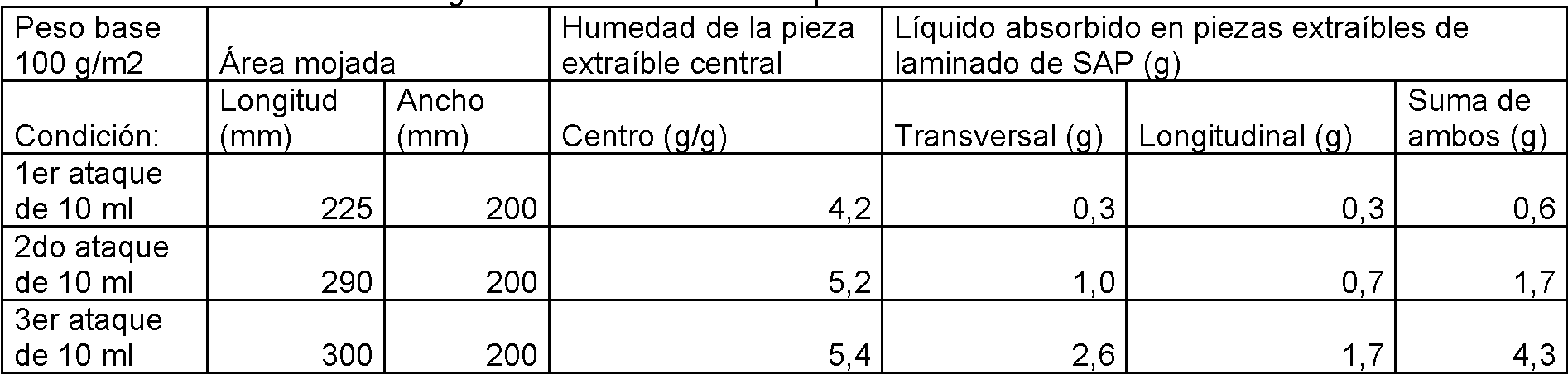
nfi r i n 4: "P n " n i z l min APnfi r i n 4: "P n" n i z l min AP

Confi uración 5: "Pana" con laminado en ambos ladosConfi uration 5: "Corduroy" with laminate on both sides

Las pruebas preliminares y de confirmación de las configuraciones 3 y 4 para dos ataques arrojaron resultados relativos similares entre ambas como se ve anteriormente.Preliminary and confirmatory tests of settings 3 and 4 for two attacks yielded similar relative results between the two as seen above.
En estos resultados se encontró que cuando el líquido se absorbía en las piezas extraíbles de laminado de SAP, la pieza extraíble central se volvió menos húmeda, sugiriendo que el sistema en el experimento anterior está funcionando de manera similar al material de la presente invención.In these results it was found that when the liquid was absorbed into the SAP laminate removable parts, the central removable part became less moist, suggesting that the system in the previous experiment is working in a similar way to the material of the present invention.
En la medida en que las maquetas anteriores representan el rendimiento relativo del laminado real de la presente invención, estos resultados apuntan inesperadamente a usar el patrón de unión de pana e incluir algo de SAP adicional en ese material, ya que produce tanto el centro más seco como la transferencia de más líquido a las capas laminadas de SAP adyacentes.To the extent that the mockups above represent the relative performance of the actual laminate of the present invention, these results unexpectedly point to using the corduroy bonding pattern and including some additional SAP in that material as it produces both the driest core such as the transfer of more liquid to the adjacent SAP laminate layers.
Se esperaba que la capa de absorción con un patrón unido de "círculos" que contuviera menos SAP y que se absorbiera libremente en ambas direcciones, transversal y longitudinal, transfiriera más líquido a las piezas extraíbles de laminado de SAP ya que se esperaba que humedeciera mejor a ambos y que la distancia de absorción fuera menos inhibida por la absorción de SAP dentro de la capa de absorción. En cambio, lo que sucedió fue que las piezas de laminado de SAP extraíbles en la posición longitudinal en el sistema de pana absorbieron mucho más líquido y combinaron esa mejor transferencia de líquido fuera de la capa de absorción con la acción de secado adicional del SAP dentro de la lámina, consiguiendo una pieza extraíble en el centro con la menor humedad. The absorption layer with a bonded pattern of "circles" containing less SAP and being freely absorbed in both transverse and longitudinal directions was expected to transfer more liquid to the removable SAP laminate parts as it was expected to wet out better. both and that the absorption distance was less inhibited by the absorption of SAP within the absorption layer. Instead, what happened was that the removable SAP laminate pieces in the longitudinal position in the corduroy system absorbed much more liquid and combined that better transfer of liquid out of the absorption layer with the additional drying action of the SAP within. of the sheet, achieving a removable piece in the center with the least humidity.
Claims (13)
Applications Claiming Priority (2)
| Application Number | Priority Date | Filing Date | Title |
|---|---|---|---|
| US201461991091P | 2014-05-09 | 2014-05-09 | |
| PCT/US2015/029807 WO2015171972A1 (en) | 2014-05-09 | 2015-05-08 | Layered absorbent structure with wicking performance |
Publications (1)
| Publication Number | Publication Date |
|---|---|
| ES2809452T3 true ES2809452T3 (en) | 2021-03-04 |
Family
ID=54366830
Family Applications (1)
| Application Number | Title | Priority Date | Filing Date |
|---|---|---|---|
| ES15789298T Active ES2809452T3 (en) | 2014-05-09 | 2015-05-08 | Absorbent layered structure with wicking effect |
Country Status (4)
| Country | Link |
|---|---|
| US (1) | US10813799B2 (en) |
| EP (1) | EP3139888B1 (en) |
| ES (1) | ES2809452T3 (en) |
| WO (1) | WO2015171972A1 (en) |
Families Citing this family (17)
| Publication number | Priority date | Publication date | Assignee | Title |
|---|---|---|---|---|
| US9789012B2 (en) | 2014-02-28 | 2017-10-17 | Attends Healthcare Products, Inc. | Absorbent article with multi-layer folded absorbent core |
| EP3110356B1 (en) * | 2014-02-28 | 2022-03-30 | EAM Corporation | Novel absorbent laminate for disposable absorbent articles |
| GB201407056D0 (en) * | 2014-04-22 | 2014-06-04 | Essentra Filter Products Dev Co Pte Ltd | Smoking article |
| ES2809452T3 (en) | 2014-05-09 | 2021-03-04 | Eam Corp | Absorbent layered structure with wicking effect |
| US9739068B2 (en) * | 2015-01-31 | 2017-08-22 | Ramshorn Corporation | Concrete curing blanket |
| GB2554651B (en) | 2016-09-30 | 2019-08-28 | Adv Med Solutions Ltd | Nonwoven Fabric Comprising Gelling Fibres |
| WO2018112229A1 (en) * | 2016-12-14 | 2018-06-21 | Eam Corporation | Absorbent laminates, absorbent cores and disposable articles utilizing the absorbent laminates, and related methods |
| CN107974765B (en) * | 2017-10-25 | 2020-10-27 | 福建明瑞新材料发展有限公司 | Non-woven fabric composite flow guide layer and preparation method thereof |
| EP3801424B1 (en) | 2018-05-28 | 2025-01-22 | Attends Healthcare Products, Inc. | Dryness layer laminate for absorbent articles |
| CN109820650A (en) * | 2019-02-13 | 2019-05-31 | 深圳市棉芯科技有限公司 | A kind of absorbent article and its core |
| KR20230005255A (en) * | 2020-04-30 | 2023-01-09 | 킴벌리-클라크 월드와이드, 인크. | Absorbent Composite Containing Embossed Superabsorbent Material |
| CN116437888A (en) * | 2020-08-25 | 2023-07-14 | 金伯利-克拉克环球有限公司 | Absorbent structure and method of making absorbent structure |
| GB2614633B (en) * | 2020-08-25 | 2025-05-14 | Kimberly Clark Co | Absorbent structures and methods for manufacturing absorbent structures |
| US20230329919A1 (en) * | 2020-08-25 | 2023-10-19 | Kimberly-Clark Worldwide, Inc. | Absorbent structures and methods for manufacturing absorbent structures |
| GB2613314B (en) * | 2020-08-25 | 2025-02-05 | Kimberly Clark Co | Absorbent structures and methods for manufacturing absorbent structures |
| CN116261440A (en) * | 2020-08-25 | 2023-06-13 | 金伯利-克拉克环球有限公司 | Absorbent structure and method of manufacturing an absorbent structure |
| WO2023064509A1 (en) * | 2021-10-13 | 2023-04-20 | Hello Hazel, Inc. | Absorbent garment |
Family Cites Families (18)
| Publication number | Priority date | Publication date | Assignee | Title |
|---|---|---|---|---|
| US4100324A (en) * | 1974-03-26 | 1978-07-11 | Kimberly-Clark Corporation | Nonwoven fabric and method of producing same |
| US4443512A (en) * | 1981-09-22 | 1984-04-17 | Colgate-Palmolive Company | Absorbent article with densified areas |
| AU634849B2 (en) | 1990-01-16 | 1993-03-04 | Chicopee | Absorbent fibrous structure |
| CA2116953C (en) * | 1993-10-29 | 2003-08-19 | Kimberly-Clark Worldwide, Inc. | Absorbent article which includes superabsorbent material located in discrete elongate pockets placed in selected patterns |
| US5462538A (en) * | 1993-12-16 | 1995-10-31 | Mcneil-Ppc, Inc. | Molten adhesive fibers and products made therefrom |
| US5562645A (en) * | 1995-05-31 | 1996-10-08 | Kimberly-Clark Corporation | Article with soft absorbent pulp sheet |
| US6675702B1 (en) | 1998-11-16 | 2004-01-13 | Alexander Maksimow | Method and device for producing a strip of cellulose fiber material for use in hygiene articles |
| US20030208175A1 (en) * | 2000-06-12 | 2003-11-06 | Gross James R. | Absorbent products with improved vertical wicking and rewet capability |
| US20030105442A1 (en) | 2001-11-30 | 2003-06-05 | Johnston Lee W. | Convection of absorbent cores providing enhanced thermal transmittance |
| US6923926B2 (en) * | 2002-01-16 | 2005-08-02 | Paragon Trade Brands, Inc. | Method and apparatus for forming tow-based absorbent structures with a single casing sheet |
| US20030135178A1 (en) * | 2002-01-17 | 2003-07-17 | Hansen Ebba A. | Absorbent laminate |
| US20040024375A1 (en) * | 2002-08-02 | 2004-02-05 | John Litvay | Multi-functional tissue for absorbent articles |
| US8314286B2 (en) * | 2003-05-23 | 2012-11-20 | Mcneil-Ppc, Inc. | Flexible liquid absorbing structure |
| WO2005041815A2 (en) * | 2003-10-21 | 2005-05-12 | Rayonier Products And Financial Services Company | Composite absorbent structures with nonwoven substrates with improved lamination integrity |
| US20100318047A1 (en) * | 2009-06-16 | 2010-12-16 | Ducker Paul M | Absorbent, nonwoven material exhibiting z-direction density gradient |
| US20110162989A1 (en) * | 2010-01-06 | 2011-07-07 | Ducker Paul M | Ultra thin laminate with particulates in dense packages |
| EP2671554B1 (en) * | 2012-06-08 | 2016-04-27 | The Procter & Gamble Company | Absorbent core for use in absorbent articles |
| ES2809452T3 (en) | 2014-05-09 | 2021-03-04 | Eam Corp | Absorbent layered structure with wicking effect |
-
2015
- 2015-05-08 ES ES15789298T patent/ES2809452T3/en active Active
- 2015-05-08 WO PCT/US2015/029807 patent/WO2015171972A1/en not_active Ceased
- 2015-05-08 EP EP15789298.5A patent/EP3139888B1/en active Active
- 2015-05-08 US US14/707,050 patent/US10813799B2/en active Active
Also Published As
| Publication number | Publication date |
|---|---|
| EP3139888B1 (en) | 2020-06-24 |
| EP3139888A4 (en) | 2017-12-06 |
| US20150320617A1 (en) | 2015-11-12 |
| WO2015171972A1 (en) | 2015-11-12 |
| EP3139888A1 (en) | 2017-03-15 |
| US10813799B2 (en) | 2020-10-27 |
Similar Documents
| Publication | Publication Date | Title |
|---|---|---|
| ES2809452T3 (en) | Absorbent layered structure with wicking effect | |
| US11672710B2 (en) | Absorbent article with multi-layer folded absorbent core | |
| ES2826124T3 (en) | Absorbent structure with discrete acquisition cells | |
| US10905604B2 (en) | Unitary absorbent structures comprising an absorbent core and/or an acquisition and dispersion layer for absorbent articles | |
| ES2270745T5 (en) | Unit fluid acquisition, storage and absorption material | |
| ES2210323T3 (en) | ABSORBENT BODY WITH IMPROVED PERMEABILITY TO LIQUIDS. | |
| JP6022683B2 (en) | Absorbent core for use in absorbent articles | |
| ES2539727T3 (en) | Water absorbing laminar structure | |
| ES2197916T3 (en) | DENSIFICABLE FIBERS AND METHOD FOR YOUR PRODUCTION. | |
| CN102883693B (en) | Flexible superabsorbent material | |
| US20170135870A1 (en) | Absorbent cores having material free areas | |
| ES2686023T5 (en) | Fluid absorbent article | |
| US10632029B2 (en) | Absorbent cores having material free areas | |
| US10806643B2 (en) | Absorbent laminate with multiple substrates | |
| KR20120010233A (en) | Absorbent sheet | |
| BR102015024913B1 (en) | ABSORBENT ARTICLE | |
| US20230248580A1 (en) | Absorbent article with improved core and method of making | |
| ES3022986T3 (en) | Absorbent article with improved multi-layered core | |
| CN101427962A (en) | Absorbent article including an absorbent layer having a plurality of spaced beam elements | |
| WO2018116893A1 (en) | Absorbent body and method for producing same |