ES2750252T3 - Modifications of fan blade with sleeve - Google Patents
Modifications of fan blade with sleeve Download PDFInfo
- Publication number
- ES2750252T3 ES2750252T3 ES08798241T ES08798241T ES2750252T3 ES 2750252 T3 ES2750252 T3 ES 2750252T3 ES 08798241 T ES08798241 T ES 08798241T ES 08798241 T ES08798241 T ES 08798241T ES 2750252 T3 ES2750252 T3 ES 2750252T3
- Authority
- ES
- Spain
- Prior art keywords
- fan blade
- fan
- flap
- hub
- approximately
- Prior art date
- Legal status (The legal status is an assumption and is not a legal conclusion. Google has not performed a legal analysis and makes no representation as to the accuracy of the status listed.)
- Active
Links
Classifications
-
- F—MECHANICAL ENGINEERING; LIGHTING; HEATING; WEAPONS; BLASTING
- F04—POSITIVE - DISPLACEMENT MACHINES FOR LIQUIDS; PUMPS FOR LIQUIDS OR ELASTIC FLUIDS
- F04D—NON-POSITIVE-DISPLACEMENT PUMPS
- F04D29/00—Details, component parts, or accessories
- F04D29/26—Rotors specially for elastic fluids
- F04D29/32—Rotors specially for elastic fluids for axial flow pumps
- F04D29/38—Blades
- F04D29/388—Blades characterised by construction
-
- F—MECHANICAL ENGINEERING; LIGHTING; HEATING; WEAPONS; BLASTING
- F04—POSITIVE - DISPLACEMENT MACHINES FOR LIQUIDS; PUMPS FOR LIQUIDS OR ELASTIC FLUIDS
- F04D—NON-POSITIVE-DISPLACEMENT PUMPS
- F04D29/00—Details, component parts, or accessories
- F04D29/26—Rotors specially for elastic fluids
- F04D29/32—Rotors specially for elastic fluids for axial flow pumps
- F04D29/34—Blade mountings
Landscapes
- Engineering & Computer Science (AREA)
- Mechanical Engineering (AREA)
- General Engineering & Computer Science (AREA)
- Structures Of Non-Positive Displacement Pumps (AREA)
Abstract
Una aleta para un aspa de ventilador, incluyendo un elemento vertical (172), estando formada una interfaz entre un primer extremo de un aspa de ventilador (800) y el elemento vertical (172), incluyendo además la aleta un elemento de montaje (190) conectado al elemento vertical (172), donde el elemento de montaje (190) está configurado para el montaje del elemento vertical (172) con relación al primer extremo de aspa de ventilador, estando configurada al menos una porción del elemento de montaje (190) para ajuste dentro del primer extremo de aspa de ventilador, donde el aspa de ventilador (800) está configurada para montaje en un cubo de ventilador en un segundo extremo del aspa de ventilador (800), estando el segundo extremo enfrente del primer extremo, caracterizada porque la aleta incluye además un manguito (200) que se extiende desde el elemento vertical (172), donde el manguito (200) está configurado para cubrir al menos una porción de la interfaz.A fin for a fan blade, including a vertical element (172), an interface being formed between a first end of a fan blade (800) and the vertical element (172), the fin further including a mounting element (190 ) connected to the vertical element (172), where the mounting element (190) is configured for mounting the vertical element (172) relative to the first fan blade end, at least a portion of the mounting element (190 ) for fit within the first fan blade end, where the fan blade (800) is configured for mounting in a fan hub at a second end of the fan blade (800), the second end being opposite the first end, characterized in that the fin further includes a sleeve (200) extending from the vertical member (172), where the sleeve (200) is configured to cover at least a portion of the interface.
Description
DESCRIPCIÓNDESCRIPTION
Modificaciones de aspa de ventilador con manguitoModifications of fan blade with sleeve
Antecedentes de la invenciónBackground of the Invention
La presente invención se refiere en general a una aleta adecuada para uso con un aspa de ventilador.The present invention generally relates to a fin suitable for use with a fan blade.
Las personas que trabajan en estructuras grandes, por ejemplo, almacenes y plantas de fabricación, pueden estar expuestas a condiciones de trabajo que van desde incómodas a peligrosas. Lo mismo puede aplicarse también a los entornos agrícolas, por ejemplo, en una estructura llena de ganado. En un día caluroso, la temperatura interior del aire puede llegar a un punto donde una persona u otro animal es incapaz de mantener una temperatura sana o deseable del cuerpo. En zonas donde las temperaturas son incómoda e inseguramente altas, puede ser deseable tener un dispositivo que pueda crear o mejorar el flujo de aire dentro de la zona. Tal flujo de aire puede facilitar, en parte, una reducción de la temperatura de la zona.People who work in large structures, such as warehouses and manufacturing plants, may be exposed to working conditions ranging from uncomfortable to dangerous. The same can also apply to agricultural settings, for example, in a structure full of livestock. On a hot day, the indoor air temperature can reach a point where a person or other animal is unable to maintain a healthy or desirable body temperature. In areas where temperatures are uncomfortable and unsafely high, it may be desirable to have a device that can create or improve air flow within the area. Such an air flow may facilitate, in part, a reduction in the temperature of the area.
Además, algunas actividades que se desarrollan en estos entornos, soldar u operar motores de combustión interna, pueden crear contaminantes transportados por el aire que pueden ser nocivos para los sujetos expuestos. Los efectos de los contaminantes transportados por el aire pueden ser amplificados si el flujo de aire en la zona es inferior al ideal. En estas situaciones y otras similares puede ser deseable tener un dispositivo que cree o mejore el flujo de aire dentro de la zona. Tal flujo de aire puede facilitar, en parte, la reducción de los efectos nocivos de contaminantes, por ejemplo, mediante dilución y/o extracción de contaminantes.Additionally, some activities that take place in these environments, welding or operating internal combustion engines, can create airborne contaminants that can be harmful to exposed subjects. The effects of airborne pollutants can be amplified if the air flow in the area is less than ideal. In these and similar situations it may be desirable to have a device that creates or improves air flow within the area. Such air flow may facilitate, in part, the reduction of the harmful effects of contaminants, for example, by dilution and / or removal of contaminants.
En algunas estructuras y entornos, el calor que se recoge y permanece cerca del techo de la estructura puede crear un problema. Éste puede ser importante donde la zona cerca del suelo de la estructura está relativamente más fría. Los expertos en la técnica reconocerán inmediatamente las desventajas que pueden surgir por tener esta u otra distribución desequilibrada del aire/temperatura. En estas situaciones y otras similares, puede ser deseable tener un dispositivo que cree o mejore el flujo de aire dentro de la zona. Tal flujo de aire puede facilitar, en parte, la desestratificación y la inducción de una distribución más ideal del aire/temperatura.In some structures and environments, the heat that collects and stays near the roof of the structure can create a problem. This may be important where the area near the floor of the structure is relatively colder. Those skilled in the art will immediately recognize the disadvantages that may arise from having this or any other unbalanced air / temperature distribution. In these and similar situations, it may be desirable to have a device that creates or improves air flow within the area. Such an air flow can facilitate, in part, the delamination and induction of a more ideal air / temperature distribution.
También puede ser deseable tener un ventilador capaz de reducir el consumo de energía. Tal reducción de consumo de energía puede lograrse con un ventilador que funcione eficientemente (por ejemplo, se requiere menos potencia para accionar el ventilador en comparación con otros ventiladores). También puede lograrse una reducción del consumo de energía con un ventilador que mejore la distribución del aire, reduciendo por ello los costos de calefacción o refrigeración asociados con otros dispositivos.It may also be desirable to have a fan capable of reducing energy consumption. Such a reduction in power consumption can be achieved with an efficiently operating fan (eg less power is required to drive the fan compared to other fans). A reduction in energy consumption can also be achieved with a fan that improves air distribution, thereby reducing heating or cooling costs associated with other devices.
EP 1619391 describe una aleta que incluye un elemento vertical y un elemento de montaje. El elemento de montaje está configurado para facilitar el montaje de la aleta en la punta de un aspa de ventilador. El elemento vertical está configurado de manera que se extienda perpendicularmente con relación a la punta de un aspa de ventilador.EP 1619391 describes a flap that includes a vertical element and a mounting element. The mounting element is configured to facilitate mounting the fin on the tip of a fan blade. The vertical element is configured so that it extends perpendicularly relative to the tip of a fan blade.
La invención se define por las reivindicaciones.The invention is defined by the claims.
Breve descripción de los dibujosBrief description of the drawings
Los dibujos acompañantes incorporados y que forman una parte de la memoria descriptiva ilustran varios aspectos de la presente invención, y conjuntamente con la descripción sirven para explicar los principios de la invención; bien entendido, sin embargo, que esta invención no se limita a las disposiciones exactas mostradas. En los dibujos, números de referencia análogos se refieren a elementos análogos en las varias vistas. En los dibujos:The accompanying drawings incorporated in and forming a part of the specification illustrate various aspects of the present invention, and together with the description serve to explain the principles of the invention; It is understood, however, that this invention is not limited to the exact arrangements shown. In the drawings, like reference numbers refer to like elements in the various views. In the drawings:
La figura 1 es una vista en planta de un cubo para montar aspas de ventilador.Figure 1 is a plan view of a hub for mounting fan blades.
La figura 2 es una vista en sección transversal de una paleta de aspa de ventilador ejemplar.FIG. 2 is a cross sectional view of an exemplary fan blade blade.
La figura 3 es una vista en sección transversal de una paleta de aspa de ventilador ejemplar alternativa.Figure 3 is a cross sectional view of an alternative exemplary fan blade vane.
La figura 4 ilustra un gráfico que representa dos elipses.Figure 4 illustrates a graph representing two ellipses.
La figura 5 ilustra una porción del gráfico de la figura 4.Figure 5 illustrates a portion of the graph in Figure 4.
La figura 6 es una vista lateral de una modificación de aspa de ventilador de aleta ejemplarFIG. 6 is a side view of an exemplary fin fan blade modification.
La figura 7 es una vista en sección transversal de la aleta de la figura 6.Figure 7 is a cross-sectional view of the flap of Figure 6.
La figura 8 es una vista superior de la aleta de la figura 6.Figure 8 is a top view of the flap of Figure 6.
La figura 9 es una vista de extremo del aspa de ventilador de la figura 2 modificada con la aleta de la figura 6. Figure 9 is an end view of the fan blade of Figure 2 modified with the flap of Figure 6.
La figura 10 es una vista en perspectiva despiezada del conjunto de aleta-aspa de la figura 9.Figure 10 is an exploded perspective view of the fin-blade assembly of Figure 9.
La figura 11 es una vista en perspectiva de una aleta alternativa ejemplar.Figure 11 is a perspective view of an exemplary alternate flap.
La figura 12 es una vista en perspectiva de la aleta de la figura 11 montada en un aspa de ventilador.Figure 12 is a perspective view of the fin of Figure 11 mounted on a fan blade.
La figura 13 es una vista en sección transversal del conjunto de aleta-aspa de la figura 12.Figure 13 is a cross sectional view of the fin-blade assembly of Figure 12.
Las figuras 11-13 muestran realizaciones de la invención, mientras que las figuras 1-10 describen ejemplos no reivindicados.Figures 11-13 show embodiments of the invention, while Figures 1-10 describe unclaimed examples.
Ahora se hará referencia en detalle a la presente realización preferida de la invención, cuyo ejemplo se ilustra en los dibujos acompañantes.Reference will now be made in detail to the present preferred embodiment of the invention, the example of which is illustrated in the accompanying drawings.
Descripción detallada de una realización de la invenciónDetailed description of an embodiment of the invention
Con referencia ahora a los dibujos en detalle, donde los números análogos indican los mismos elementos en todas las vistas, la figura 1 representa un cubo de ventilador ejemplar (10), que puede ser usado para proporcionar un ventilador que tiene aspas de ventilador (30 o 50). En el ejemplo presente, el cubo de ventilador (10) incluye una pluralidad de elementos de montaje de cubo (12) en los que las aspas de ventilador (30 o 50) pueden montarse. En una realización, el cubo de ventilador (10) está acoplado a un mecanismo de accionamiento para girar el cubo de ventilador (10) a velocidades seleccionables o predeterminadas. Un conjunto de cubo adecuado puede incluir así el cubo (10) y un mecanismo de movimiento acoplado al cubo (10). Naturalmente, un conjunto de cubo puede incluir otros varios elementos, incluyendo un cubo diferente, y el cubo de ventilador (10) puede ser movido por cualesquiera medios adecuados. Además, el cubo de ventilador (10) puede tener cualquier número adecuado de elementos de montaje de cubo (12).Referring now to the drawings in detail, where like numbers indicate the same elements in all views, Figure 1 depicts an exemplary fan hub (10), which can be used to provide a fan having fan blades (30 or 50). In the present example, the fan hub (10) includes a plurality of hub mounting elements (12) on which the fan blades (30 or 50) can be mounted. In one embodiment, the fan hub (10) is coupled to a drive mechanism to rotate the fan hub (10) at selectable or predetermined speeds. A suitable hub assembly may thus include the hub (10) and a movement mechanism coupled to the hub (10). Naturally, a hub assembly can include various other elements, including a different hub, and the fan hub (10) can be moved by any suitable means. Furthermore, the fan hub (10) can have any suitable number of hub mounting elements (12).
Como se representa en las figuras 1 a 3, cada elemento de montaje de cubo (12) tiene una superficie superior (14) y una superficie inferior (16), que terminan en un borde de entrada (18) y un borde de salida (20). Además, cada elemento de montaje de cubo (12) incluye una abertura (22) formada a través de la superficie superior (14) y que pasa a través de la superficie inferior (16). En el ejemplo presente, la abertura (22) está dimensionada para recibir el sujetador (26). Cada elemento de montaje de cubo (12) está configurado para recibir el aspa de ventilador (30 o 50). Los expertos en la técnica apreciarán en vista de la presente descripción que los elementos de montaje de cubo (12) se pueden disponer en varias configuraciones alternativas.As depicted in Figures 1 to 3, each hub mounting element (12) has an upper surface (14) and a lower surface (16), which terminate at a leading edge (18) and a trailing edge ( twenty). In addition, each hub mounting element (12) includes an opening (22) formed through the top surface (14) and passing through the bottom surface (16). In the present example, opening (22) is sized to receive fastener (26). Each hub mounting element (12) is configured to receive the fan blade (30 or 50). Those skilled in the art will appreciate in view of the present disclosure that the hub mounting elements (12) can be arranged in various alternative configurations.
En una realización, las aspas de ventilador (30 o 50) están montadas en el conjunto de cubo descrito en la Patente de Estados Unidos número 6.244.821. Naturalmente, las aspas de ventilador (30 o 50) pueden ir montadas en cualquier otro cubo y/o conjunto de cubo. Un conjunto de cubo adecuado puede operar para girar el cubo (10) a cualquier velocidad angular adecuada. A modo de ejemplo solamente, tal velocidad angular puede estar en cualquier lugar en el rango de aproximadamente 7 y 108 revoluciones por minuto.In one embodiment, the fan blades (30 or 50) are mounted on the hub assembly described in US Patent No. 6,244,821. Naturally, the fan blades (30 or 50) can be mounted on any other hub and / or hub assembly. A suitable hub assembly can operate to rotate the hub (10) at any suitable angular velocity. By way of example only, such angular velocity may be anywhere in the range of about 7 to 108 revolutions per minute.
La figura 2 representa una sección transversal de aspa de ventilador ejemplar (30) que tiene un borde de salida curvado (38), montada en cubo (10). La sección transversal se ha tomado a lo largo de un plano transversal situado en el centro de aspa de ventilador (30), mirando hacia el cubo (10). El aspa de ventilador (30) tiene una superficie superior (32) y una superficie inferior (34), cada una de las cuales termina en un borde delantero (36) y un borde de salida (38). Como se representa, un borde de salida (38) tiene una inclinación de aproximadamente 45° con relación a la porción de superficie superior (32) que está próxima al borde de salida (38) y una porción de superficie inferior (34) que está próxima al borde de salida (38). Naturalmente, el borde de salida (38) puede tener cualquier otra inclinación adecuada, por ejemplo, de 0° a modo de ejemplo solamente, en la medida en que incluye una sola superficie plana. Otras configuraciones adecuadas del borde de salida (38) serán evidentes a los expertos en la técnica a la luz de las ideas expuestas en este documento.Figure 2 depicts a cross section of an exemplary fan blade (30) having a curved, trailing edge (38) mounted on a hub (10). The cross section has been taken along a transverse plane located in the center of the fan blade (30), facing the hub (10). The fan blade (30) has an upper surface (32) and a lower surface (34), each of which ends at a leading edge (36) and a trailing edge (38). As shown, a trailing edge (38) has an inclination of approximately 45 ° relative to the upper surface portion (32) that is close to the trailing edge (38) and a lower surface portion (34) that is near the trailing edge (38). Naturally, the trailing edge 38 may have any other suitable inclination, for example 0 ° by way of example only, to the extent that it includes a single flat surface. Other suitable trailing edge configurations (38) will be apparent to those skilled in the art in light of the ideas set forth in this document.
En el ejemplo presente, el aspa de ventilador (30) es sustancialmente hueca. Una pluralidad de nervios o salientes (40) están situados dentro del aspa de ventilador (30). Como se representa, cuando el elemento de montaje de cubo (12) está insertado en el aspa de ventilador (30), nervios o salientes (40) están colocados de tal manera que contacten la superficie superior (14), la superficie inferior (16), el borde de entrada (18), y el borde de salida (20) del elemento de montaje de cubo (12). Los salientes (40) proporcionan así un ajuste apretado entre el aspa de ventilador (30) y el elemento de montaje de cubo (12). Configuraciones alternativas del aspa de ventilador (30), incluyendo, aunque sin limitación, las que afectan a la relación entre el aspa de ventilador (30) y el elemento de montaje de cubo (12), serán evidentes a los expertos en la técnica a la luz de las ideas expuestas en este documento.In the present example, the fan blade 30 is substantially hollow. A plurality of ribs or projections (40) are located within the fan blade (30). As shown, when the hub mounting element (12) is inserted into the fan blade (30), ribs or projections (40) are positioned such that they contact the upper surface (14), the lower surface (16 ), the leading edge (18), and the trailing edge (20) of the hub mounting element (12). The protrusions (40) thus provide a tight fit between the fan blade (30) and the hub mounting element (12). Alternative configurations of the fan blade (30), including, but not limited to, those affecting the relationship between the fan blade (30) and the hub mounting element (12), will be apparent to those skilled in the art to the light of the ideas exposed in this document.
En el sentido en que se usa aquí, a términos como "cuerda", "longitud de cuerda”, " grosor máximo", "inclinación máxima", "ángulo de ataque" y análogos, se les atribuirá el mismo significado que el atribuido a los términos usados en la técnica de las alas de aviones u otro diseño de superficie aerodinámica. En una realización, el aspa de ventilador (30) tiene una longitud de cuerda de aproximadamente 6,44 pulgadas (163,58 mm). El aspa de ventilador (30) tiene un grosor máximo de aproximadamente 16,2% de la cuerda; y una inclinación máxima de aproximadamente 12,7% de la cuerda. El radio del borde de entrada (36) es aproximadamente 3,9% de la cuerda. El radio del cuadrante de borde de salida (38) de la superficie inferior (34) es aproximadamente 6,8% de la cuerda. En una realización alternativa, el aspa de ventilador (30) tiene una cuerda de aproximadamente 7 pulgadas. En otra realización, el aspa de ventilador (30) tiene una cuerda de aproximadamente 6,6875 pulgadas (169,86 mm). Naturalmente, puede usarse cualesquiera otras dimensiones y/o proporciones adecuadas.As used herein, terms such as "chord", "chord length", "maximum thickness", "maximum inclination", "angle of attack", and the like will be attributed the same meaning as that attributed to the terms used in the aircraft wing technique or other aerodynamic surface design. In one embodiment, the blade of fan (30) has a chord length of approximately 6.44 inches (163.58 mm). The fan blade (30) has a maximum thickness of approximately 16.2% of the chord; and a maximum incline of approximately 12.7% of the rope. The radius of the leading edge (36) is approximately 3.9% of the chord. The radius of the trailing edge quadrant (38) of the bottom surface (34) is approximately 6.8% of the chord. In an alternative embodiment, the fan blade 30 has a cord of approximately 7 inches. In another embodiment, the fan blade 30 has a chord of approximately 6.6875 inches (169.86 mm). Naturally, any other suitable dimensions and / or proportions can be used.
A modo de ejemplo solamente, el aspa de ventilador (30) puede exhibir relaciones de elevación a resistencia al arrastre del orden de aproximadamente 39,8, en condiciones en las que el número de Reynolds es de aproximadamente 120.000 a aproximadamente 93,3, donde el número de Reynolds es de aproximadamente 250.000. Naturalmente, otras relaciones de elevación a resistencia al arrastre pueden obtenerse con el aspa de ventilador (30).By way of example only, the fan blade 30 can exhibit lift-to-drag ratios on the order of about 39.8, under conditions where the Reynolds number is from about 120,000 to about 93.3, where the Reynolds number is approximately 250,000. Naturally, other lift-to-drag ratios can be obtained with the fan blade (30).
En una realización, el aspa de ventilador (30) exhibe coeficientes de resistencia al arrastre del orden de aproximadamente 0,027, en condiciones donde el número de Reynolds es de aproximadamente 75.000 a aproximadamente 0,127, donde el número de Reynolds es de aproximadamente 112.500. Naturalmente, otros coeficientes de resistencia al arrastre pueden obtenerse con el aspa de ventilador (30).In one embodiment, the fan blade 30 exhibits drag coefficients on the order of about 0.027, under conditions where the Reynolds number is from about 75,000 to about 0.127, where the Reynolds number is from about 112,500. Naturally, other drag resistance coefficients can be obtained with the fan blade (30).
En un ejemplo, en condiciones donde el número de Reynolds es aproximadamente 200.000, el aspa de ventilador (30) mueve el aire de tal manera que hay una relación de velocidad de aproximadamente 1,6 en la superficie inferior (34) en el borde de salida (38) del aspa de ventilador (30). Pueden obtenerse otras relaciones de velocidad con el aspa de ventilador (30).In one example, under conditions where the Reynolds number is approximately 200,000, the fan blade (30) moves the air in such a way that there is a speed ratio of approximately 1.6 at the bottom surface (34) at the edge of outlet (38) of the fan blade (30). Other speed ratios can be obtained with the fan blade (30).
En una realización, el aspa de ventilador (30) proporciona aerodinámica sin pérdida para ángulos de ataque de entre aproximadamente -1° y 7°, en condiciones donde el número de Reynolds es aproximadamente 112.000; y ángulos de ataque de entre aproximadamente -2° y 10°, donde el número de Reynolds es aproximadamente 250.000. Naturalmente, estos valores son simplemente ejemplares.In one embodiment, the fan blade 30 provides lossless aerodynamics for angles of attack of between about -1 ° and 7 °, under conditions where the Reynolds number is approximately 112,000; and angles of attack between approximately -2 ° and 10 °, where the Reynolds number is approximately 250,000. Naturally, these values are simply exemplary.
La figura 3 representa una sección transversal de otra aspa de ventilador ejemplar (50) que tiene una superficie superior generalmente elíptica (52) y una superficie inferior (54), cada una de las cuales termina en un borde de entrada (56) y un borde de salida (58), montada en el cubo (10). La sección transversal se ha tomado a lo largo de un plano transversal situado en el centro del aspa de ventilador (50), mirando hacia cubo (10). En el ejemplo presente, el aspa de ventilador (50) es hueca. Una pluralidad de salientes (60) están situados dentro del aspa de ventilador (50). Como se representa, cuando el elemento de montaje de cubo (12) está insertado en el aspa de ventilador (50), los salientes (60) están colocados de tal manera que contacten la superficie superior (14), la superficie inferior (16), el borde de entrada (18), y el borde de salida (20) del elemento de montaje de cubo (12). Los salientes (60) proporcionan así un ajuste apretado entre el aspa de ventilador (50) y el elemento de montaje de cubo (12). Configuraciones alternativas para aspa de ventilador (50), incluyendo, aunque sin limitación, las que afectan a la relación entre el aspa de ventilador (50) y el elemento de montaje de cubo (12), serán evidentes a los expertos en la técnica a la luz de las ideas expuestas en este documento.Figure 3 depicts a cross section of another exemplary fan blade (50) having a generally elliptical top surface (52) and a bottom surface (54), each of which terminates at a leading edge (56) and a trailing edge (58), mounted on the hub (10). The cross section has been taken along a transverse plane located in the center of the fan blade (50), facing the hub (10). In the present example, the fan blade 50 is hollow. A plurality of protrusions (60) are located within the fan blade (50). As shown, when the hub mounting element (12) is inserted into the fan blade (50), the projections (60) are positioned such that they contact the upper surface (14), the lower surface (16) , the leading edge (18), and the trailing edge (20) of the hub mounting element (12). The protrusions (60) thus provide a tight fit between the fan blade (50) and the hub mounting element (12). Alternative configurations for fan blade (50), including, but not limited to, those affecting the relationship between the fan blade (50) and the hub mounting element (12), will be apparent to those skilled in the art to the light of the ideas exposed in this document.
Como se representa, el aspa de ventilador (50) tiene un radio de curvatura inferior hacia su borde de entrada (56), en comparación con un radio de curvatura más alto hacia su borde de salida (58). Las curvaturas del aspa de ventilador (50) pueden obtenerse, al menos en parte, a través de la generación de dos elipses usando las fórmulas siguientes. A la luz de las ideas expuestas en este documento, los expertos en la técnica apreciarán que una primera elipse, con su origen en la intersección de los ejes cartesiano x y y, puede ser generada con estas ecuaciones:As shown, the fan blade 50 has a lower radius of curvature toward its leading edge 56, compared to a higher radius of curvature toward its trailing edge 58. The curvatures of the fan blade 50 can be obtained, at least in part, through the generation of two ellipses using the following formulas. In light of the ideas set forth in this document, those skilled in the art will appreciate that a first ellipse, originating from the intersection of the Cartesian x and y axes, can be generated with these equations:
[1] x = a(COS(t)),[1] x = a (COS (t)),
yY
[2] y = b(SIN(t)>[2] y = b (SIN (t)>
dondewhere
a = longitud de radio primario,a = length of primary radius,
b = longitud de radio secundario, yb = length of secondary radius, and
t = ángulo de rotación de un radio alrededor del origen (por ejemplo, en radianes). t = angle of rotation of a radius around the origin (for example, in radians).
Consiguientemente, una primera elipse puede ser generada usando las ecuaciones anteriores. Igualmente, un conjunto de coordenadas para la primera elipse puede obtenerse usando las ecuaciones [1] y [2]. Una primera elipse ejemplar (200) se ilustra en el gráfico ilustrado en la figura 4, donde a = 3 y b = 2.Accordingly, a first ellipse can be generated using the equations above. Similarly, a set of coordinates for the first ellipse can be obtained using equations [1] and [2]. A first exemplary ellipse (200) is illustrated in the graph illustrated in Figure 4, where a = 3 and b = 2.
Las coordenadas para una segunda elipse pueden obtenerse usando estas ecuaciones:The coordinates for a second ellipse can be obtained using these equations:
[3] x2 = x(COS(e))-y(SIN(e)),[3] x2 = x (COS (e)) - y (SIN (e)),
yY
[4] yi = y (CO S(0 )) - x(SIN(0)),[4] yi = y (CO S (0)) - x (SIN (0)),
dondewhere
x2 = la segunda coordenada "x" después de una rotación hacia la izquierda de la primera elipse 0 radianes alrededor del origen, yx2 = the second coordinate "x" after a counterclockwise rotation of the first ellipse 0 radians around the origin, and
y2 = la segunda coordenada "y" después de una rotación hacia la izquierda de la primera elipse 0 radianes alrededor del origen.y2 = the second coordinate "y" after a counterclockwise rotation of the first ellipse 0 radians around the origin.
Así, las dimensiones de la segunda elipse son dependientes de las dimensiones de la primera elipse. La segunda elipse ejemplar (300) se ilustra en el gráfico ilustrado en la figura 4, donde 0 = 0,525 radianes. A la luz de las ideas expuestas en este documento, se apreciará que, donde se representan una primera y una segunda elipse según las ecuaciones [1] a [4], las dos elipses pueden intersecar en cuatro puntos ("intersecciones de elipse"). La figura 4 representa cuatro intersecciones de elipse (400) entre la primera elipse (200) y la segunda elipse (300).Thus, the dimensions of the second ellipse are dependent on the dimensions of the first ellipse. The second exemplary ellipse (300) is illustrated in the graph illustrated in Figure 4, where 0 = 0.525 radians. In light of the ideas set forth in this document, it will be appreciated that where a first and a second ellipse are represented according to equations [1] to [4], the two ellipses may intersect at four points ("ellipse intersections") . Figure 4 depicts four ellipse intersections (400) between the first ellipse (200) and the second ellipse (300).
La curvatura de la superficie superior (52) y la superficie inferior (54) se puede basar, al menos en parte, en la curvatura de las elipses primera y segunda entre dos intersecciones de elipse consecutivas. Un ejemplo de tal segmento de la primera elipse (200) y la segunda elipse (300) se representa en la figura 5, que ilustra la porción de las elipses (200 y 300) entre intersecciones de elipse consecutivas (400). Consiguientemente, las ecuaciones [1] a [4] pueden ser usadas para generar coordenadas superficiales para al menos una porción de la superficie superior (52) y la superficie inferior (54) del aspa de ventilador (50).The curvature of the top surface 52 and the bottom surface 54 can be based, at least in part, on the curvature of the first and second ellipses between two consecutive ellipse intersections. An example of such a segment of the first ellipse (200) and the second ellipse (300) is depicted in Figure 5, illustrating the portion of the ellipses (200 and 300) between consecutive ellipse intersections (400). Accordingly, equations [1] to [4] can be used to generate surface coordinates for at least a portion of the upper surface (52) and the lower surface (54) of the fan blade (50).
A la luz de las ideas expuestas en este documento, se apreciará que la relación longitud de cuerda a grosor del aspa de ventilador (50) puede variar con la cantidad de rotación, 0, con relación a las dos elipses.In light of the ideas set forth in this document, it will be appreciated that the ratio of chord length to thickness of the fan blade 50 may vary with the amount of rotation, 0, relative to the two ellipses.
Naturalmente, porciones del aspa de ventilador (50) pueden desviarse de la curvatura de las elipses primera y segunda. A modo de ejemplo solamente, y como se representa en la figura 3, el borde de entrada (56) puede ser modificado de manera que tenga una curvatura generalmente circular. Otras desviaciones serán evidentes a los expertos en la técnica a la luz de las ideas expuestas en este documento.Naturally, portions of the fan blade 50 can deviate from the curvature of the first and second ellipses. By way of example only, and as shown in Figure 3, the leading edge (56) can be modified so that it has a generally circular curvature. Other deviations will be apparent to those skilled in the art in light of the ideas set forth in this document.
En una realización, el aspa de ventilador (50) se crea usando las ecuaciones [1] a [4] con a = 3 unidades, b = 2 unidades, y 0 = 0,525 radianes. En esta realización, el aspa de ventilador (50) encaja con el borde circular delantero (56) que tiene un diámetro de 3,5% de longitud de cuerda. Esta curvatura de borde delantero (56) se ajusta tangencialmente a la de la superficie superior (52) y la superficie inferior (54). Tal ajuste puede contemplarse comparando las figuras 3 y 5. Naturalmente, pueden usarse otras dimensiones.In one embodiment, the fan blade 50 is created using equations [1] to [4] with a = 3 units, b = 2 units, and 0 = 0.525 radians. In this embodiment, the fan blade (50) engages the leading circular edge (56) having a diameter of 3.5% chord length. This leading edge curvature (56) is tangentially adjusted to that of the upper surface (52) and the lower surface (54). Such an adjustment can be seen by comparing Figures 3 and 5. Naturally, other dimensions can be used.
En una realización, el aspa de ventilador (50) tiene una longitud de cuerda de aproximadamente 7,67 pulgadas (194,818 mm). En otra realización, el aspa de ventilador tiene una longitud de cuerda de aproximadamente 7,687 pulgadas (195,250 mm). Naturalmente, el aspa de ventilador (50) puede tener cualquier otra longitud de cuerda adecuada.In one embodiment, the fan blade 50 has a chord length of approximately 7.67 inches (194,818 mm). In another embodiment, the fan blade has a chord length of approximately 7,687 inches (195,250 mm). Naturally, the fan blade 50 can have any other suitable chord length.
En el ejemplo presente, el radio del borde de entrada (56) es aproximadamente 3,5% de la cuerda. El grosor máximo del aspa de ventilador (50) es aproximadamente 14,2% de la cuerda. La inclinación máxima del aspa de ventilador (50) es aproximadamente 15,6% de la cuerda. Naturalmente, puede usarse cualesquiera otras dimensiones adecuadas y/o proporciones.In the present example, the radius of the leading edge (56) is approximately 3.5% of the chord. The maximum thickness of the fan blade (50) is approximately 14.2% of the string. The maximum inclination of the fan blade (50) is approximately 15.6% of the rope. Naturally, any other suitable dimensions and / or proportions can be used.
En un ejemplo, un ventilador que tiene un diámetro de 24 pies (7,315 m) e incluyendo diez aspas de ventilador (50) montadas en un ángulo de ataque de 10° produce una fuerza de empuje de aproximadamente 5,2 lb. (2,359 kg) al girar a aproximadamente 7 revoluciones por minuto (rpm), desplazando aproximadamente 87.302 pies cúbicos por minuto (cfm) (41,20 m3/s). Al girar a aproximadamente 14 rpm, el ventilador produce una fuerza de empuje de aproximadamente 10,52 lb (4,772 kg), desplazando aproximadamente 124.174 cfm (58,60 m3/s). Al girar a aproximadamente 42 rpm, el ventilador produce una fuerza de empuje de aproximadamente 71,01 lb (32,21 kg), desplazando aproximadamente 322.613 cfm (152,26 m3/s). Otras fuerzas de empuje y/o volúmenes de desplazamiento pueden obtenerse con un ventilador que tiene aspas de ventilador (50).In one example, a fan having a diameter of 24 feet (7,315 m) and including ten fan blades (50) mounted at a 10 ° angle of attack produces a thrust force of approximately 5.2 lbs. (2,359 kg) when rotating at approximately 7 revolutions per minute (rpm), displacing approximately 87,302 cubic feet per minute (cfm) (41.20 m3 / s). When rotating at approximately 14 rpm, the fan produces a thrust force of approximately 10.52 lb (4,772 kg), displacing approximately 124,174 cfm (58.60 m3 / s). When rotating at approximately 42 rpm, the fan produces a pushing force of approximately 71.01 lb (32.21 kg), displacing approximately 322,613 cfm (152.26 m3 / s). Other thrust forces and / or displacement volumes can be obtained with a fan having fan blades (50).
A modo de ejemplo solamente, el aspa de ventilador (50) que tiene un ángulo de ataque de aproximadamente 10° puede exhibir relaciones de elevación a resistencia al arrastre del orden de aproximadamente 39, en condiciones donde el número de Reynolds es de aproximadamente 120.000 a aproximadamente 60, donde el número de Reynolds es aproximadamente 250.000. Otras relaciones de elevación a resistencia al arrastre pueden obtenerse con el aspa de ventilador (50).By way of example only, the fan blade 50 having an angle of attack of approximately 10 ° can exhibit lift-to-drag ratios on the order of approximately 39 under conditions where the Reynolds number is approximately 120,000 to approximately 60, where the Reynolds number is approximately 250,000. Other ratios of lift to drag can be obtained with the fan blade (50).
En una realización, el aspa de ventilador (50) proporciona aerodinámica sin pérdida para ángulos de ataque de entre aproximadamente 1° y 11°, en condiciones donde el número de Reynolds es aproximadamente 112.000; para ángulos de ataque de entre aproximadamente 0° y 13°, donde el número de Reynolds es aproximadamente 200.000; y para ángulos de ataque de entre aproximadamente 1° y 13°, donde el número de Reynolds es aproximadamente 250.000. Naturalmente, estos valores son simplemente ejemplares.In one embodiment, the fan blade 50 provides lossless aerodynamics for angles of attack of between about 1 ° and 11 °, under conditions where the Reynolds number is about 112,000; for angles of attack between approximately 0 ° and 13 °, where the Reynolds number is approximately 200,000; and for angles of attack between approximately 1 ° and 13 °, where the Reynolds number is approximately 250,000. Naturally, these values are simply exemplary.
En un ejemplo, un ventilador que tiene un diámetro de 14 pies (4,27 m) e incluyendo diez aspas de ventilador (50) gira a aproximadamente 25 rpm. El ventilador funciona a aproximadamente 54 vatios, con un par de aproximadamente 78,80 pulgada-libras (pulgada.lbs.) (907,89 mm kg) y un caudal de aproximadamente 34.169 cfm (16,13 m3/s). El ventilador tiene así una eficiencia de aproximadamente 632,76 cfm/vatio (0,299 m3/s/vatio).In one example, a fan that has a diameter of 14 feet (4.27 m) and includes ten fan blades (50) rotates at approximately 25 rpm. The fan runs at approximately 54 watts, with a torque of approximately 78.80 inch-pounds (in.lbs.) (907.89 mm kg) and a flow rate of approximately 34,169 cfm (16.13 m3 / s). The fan thus has an efficiency of approximately 632.76 cfm / watt (0.299 m3 / s / watt).
En otro ejemplo, un ventilador que tiene un diámetro de 14 pies (4,27 m) e incluyendo diez aspas de ventilador (50) gira a aproximadamente 37,5 rpm. El ventilador funciona a aproximadamente 82 vatios, con un par de aproximadamente 187,53 pulgada-libras (pulgada-lb) (2160,62 mm kg) y un caudal de aproximadamente 62.421 cfm (29,46 m3/s). El ventilador tiene así una eficiencia de aproximadamente 761,23 cfm/vatio (0,359 m3/s/vatio).In another example, a fan having a diameter of 14 feet (4.27 m) and including ten fan blades (50) rotates at approximately 37.5 rpm. The fan operates at approximately 82 watts, with a torque of approximately 187.53 inch-pounds (2160.62 mm kg) and a flow rate of approximately 62,421 cfm (29.46 m3 / s). The fan thus has an efficiency of approximately 761.23 cfm / watt (0.359 m3 / s / watt).
En otro ejemplo, un ventilador que tiene un diámetro de 14 pies (4,27 m) e incluyendo diez aspas de ventilador (50) gira a aproximadamente 50 rpm. El ventilador funciona a aproximadamente 263 vatios, con un par de aproximadamente 376,59 pulgada-libras (pulgada-lb) (4338,86 mm kg) y un caudal de aproximadamente 96.816 cfm (45,69 m3/s). El ventilador tiene así una eficiencia de aproximadamente 368,12 cfm/vatio (0,174 f m3/s/vatio).In another example, a fan having a diameter of 14 feet (4.27 m) and including ten fan blades (50) rotates at approximately 50 rpm. The fan operates at approximately 263 watts, with a torque of approximately 376.59 inch-pounds (4338.86 mm kg) and a flow rate of approximately 96,816 cfm (45.69 m3 / s). The fan thus has an efficiency of approximately 368.12 cfm / watt (0.174 f m3 / s / watt).
Lo que sigue puede aplicarse a cualquier aspa de ventilador, incluyendo, a modo de ejemplo solamente, el aspa de ventilador (30) o el aspa de ventilador (50):The following can be applied to any fan blade, including, by way of example only, the fan blade (30) or the fan blade (50):
En una realización, cada aspa de ventilador (30 o 50) incluye un continuo homogéneo de material. A modo de ejemplo solamente, las aspas de ventilador (30 y 50) se pueden hacer de aluminio extrusionado. Sin embargo, a la luz de las ideas expuestas en este documento, se apreciará que las aspas de ventilador (30 y/o 50) se pueden construir de cualquier otro material o materiales adecuados, incluyendo, aunque sin limitación, cualquier metal y/o plástico. Además, se apreciará a la luz de las ideas expuestas en este documento que las aspas de ventilador (30 y/o 50) se pueden hacer por cualquier método de fabricación adecuado, incluyendo, aunque sin limitación, estampado, curvado, soldadura y/o moldeo. Otros materiales adecuados y métodos de fabricación serán evidentes a los expertos en la técnica a la luz de las ideas expuestas en este documento.In one embodiment, each fan blade (30 or 50) includes a homogeneous continuum of material. By way of example only, the fan blades (30 and 50) can be made of extruded aluminum. However, in light of the ideas set forth in this document, it will be appreciated that the fan blades (30 and / or 50) can be constructed of any other suitable material or materials, including, but not limited to, any metal and / or plastic. Furthermore, it will be appreciated in light of the ideas set forth in this document that the fan blades (30 and / or 50) can be made by any suitable manufacturing method, including, but not limited to, stamping, bending, welding and / or molding. Other suitable materials and manufacturing methods will be apparent to those skilled in the art in light of the ideas set forth in this document.
Cuando el aspa de ventilador (30 o 50) está montada en el cubo (10), los elementos de montaje de cubo (12) pueden extenderse al aspa de ventilador (30 o 50) aproximadamente 6 pulgadas (152,4 mm), a modo de ejemplo solamente. Alternativamente, elementos de montaje de cubo (12) pueden extenderse al aspa de ventilador (30 o 50) a cualquier longitud adecuada. También se apreciará a la luz de las ideas expuestas en este documento que el cubo (10) puede tener elementos de montaje (12) que encajan en el exterior de las aspas de ventilador (30 o 50), más bien que dentro. Alternativamente, los elementos de montaje (12) pueden encajar tanto parcialmente dentro como parcialmente fuera de las aspas de ventilador (30 o 50).When the fan blade (30 or 50) is mounted on the hub (10), the hub mounting elements (12) can extend to the fan blade (30 or 50) approximately 6 inches (152.4 mm), to example mode only. Alternatively, hub mounting elements (12) can extend to the fan blade (30 or 50) to any suitable length. It will also be appreciated in light of the ideas set forth in this document that the hub (10) may have mounting elements (12) that fit on the outside of the fan blades (30 or 50), rather than inside. Alternatively, the mounting elements (12) can fit both partially inside and partially outside the fan blades (30 or 50).
El aspa de ventilador (30 o 50) también puede incluir una o más aberturas configuradas para alineación con aberturas (22) en el elemento de montaje de cubo (12). En esta realización, cuando las aberturas presentes en el aspa de ventilador (30 o 50) están alineadas con aberturas (22) en el elemento de montaje de cubo (12), el sujetador (26) puede insertarse a través de las aberturas para fijar el aspa de ventilador (30 o 50) al elemento de montaje de cubo (12). En una realización, el sujetador (26) es un perno. Otras alternativas adecuadas del sujetador o los sujetadores (26) serán evidentes a los expertos en la técnica a la luz de las ideas expuestas en este documento, incluyendo, aunque sin limitación, adhesivos, soldadura, etc. Consiguientemente, se entenderá que las aberturas (22) son opcionales.The fan blade (30 or 50) may also include one or more openings configured for alignment with openings (22) in the hub mounting element (12). In this embodiment, when the openings present in the fan blade (30 or 50) are aligned with openings (22) in the hub mounting element (12), the fastener (26) can be inserted through the openings to fix the fan blade (30 or 50) to the hub mounting element (12). In one embodiment, the fastener 26 is a bolt. Other suitable fastener or fastener alternatives (26) will be apparent to those skilled in the art in light of the ideas set forth herein, including, but not limited to, adhesives, solder, etc. Accordingly, openings (22) will be understood to be optional.
El aspa de ventilador (30 o 50) puede ser de aproximadamente 4, 5, 6, 7, 8, 9, 10, 11, 12, 13, o 14 pies (1,219, 1,524, 1,829, 2,133, 2,438, 2,743, 3,048, 3,353, 3,658, 3,962 o 4,267 m) de largo. Alternativamente, el aspa de ventilador (30 o 50) puede ser de cualquier otra longitud adecuada. En una realización, el aspa de ventilador (30 o 50) y el cubo (10) están dimensionados de tal manera que un ventilador incluyendo aspas de ventilador (30 o 50) y cubo (10) tiene un diámetro de aproximadamente 24 pies (7,315 m). En otra realización, el aspa de ventilador (30 o 50) y el cubo (10) están dimensionados de tal manera que un ventilador incluyendo aspas de ventilador (30 o 50) y cubo (10) tiene un diámetro de aproximadamente 14 pies (4,267 m). Otras dimensiones adecuadas serán evidentes a los expertos en la técnica a la luz de las ideas expuestas en este documento.The fan blade (30 or 50) can be approximately 4, 5, 6, 7, 8, 9, 10, 11, 12, 13, or 14 feet (1,219, 1,524, 1,829, 2,133, 2,438, 2,743, 3,048 , 3,353, 3,658, 3,962 or 4,267 m) long. Alternatively, the fan blade 30 or 50 may be of any other suitable length. In one embodiment, the fan blade (30 or 50) and hub (10) are dimensioned such that a fan including fan blades (30 or 50) and hub (10) has a diameter of approximately 24 feet (7,315 m). In another embodiment, the fan blade (30 or 50) and hub (10) are dimensioned such that a fan including fan blades (30 or 50) and hub (10) has a diameter of approximately 14 feet (4,267 m). Other suitable dimensions will be apparent to those skilled in the art in light of the ideas set forth in this document.
A la luz de las ideas expuestas en este documento, se apreciará que todas las secciones transversales a lo largo de la longitud del aspa de ventilador (30 o 50) no tienen que ser idénticas. En otros términos, la configuración del aspa de ventilador (30 o 50) no tiene que ser uniforme a lo largo de toda la longitud del aspa de ventilador (30 o 50). A modo de ejemplo solamente, una porción del "extremo de montaje de cubo" del aspa de ventilador (30 o 50) (es decir, el extremo del aspa de ventilador (30 o 50) que se montará en el cubo (10)) puede quitarse. En un ejemplo, se efectúa un corte oblicuo en el borde de entrada (56) del aspa de ventilador (50) para acomodar otra aspa (50) en el cubo (10).In light of the ideas set forth in this document, it will be appreciated that all cross sections along the length of the fan blade (30 or 50) do not have to be identical. In other words, the configuration of the fan blade (30 or 50) does not have to be uniform throughout the entire length of the fan blade (30 or 50). By way of example only, a portion of the "hub mounting end" of the fan blade (30 or 50) (ie, the end of the fan blade (30 or 50) to be mounted on the hub (10)) can be removed. In one example, an oblique cut is made at the leading edge (56) of the fan blade (50) to accommodate another blade (50) in the hub (10).
Alternativamente, el aspa de ventilador (30 o 50) se puede formar o construir de tal manera que una porción del extremo de montaje de cubo u otra porción se omita, libere o “falte” de otro modo. Se apreciará a la luz de las ideas expuestas en este documento que la ausencia de tal porción (independientemente de si se quitó o nunca estuvo) puede aliviar problemas asociados con las aspas (30 o 50) que interfieren entre sí en el cubo (10). Tal interferencia puede ser producida por varios factores, incluyendo, aunque sin limitación, la longitud de cuerda de las aspas de ventilador (30 o 50). Naturalmente, factores distintos de la interferencia pueden influir en la extracción u otra ausencia de una porción del aspa de ventilador (30 o 50). La porción ausente puede incluir una porción del borde de entrada (36 o 56), una porción del borde de salida (38 o 58) o ambas.Alternatively, the fan blade (30 or 50) can be formed or constructed such that a portion of the hub mounting end or another portion is otherwise omitted, released, or "missed". It will be appreciated in light of the ideas set forth in this document that the absence of such a portion (regardless of whether it was removed or never was) can alleviate problems associated with the blades (30 or 50) that interfere with each other in the hub (10) . Such interference can be caused by various factors, including, but not limited to, the chord length of the fan blades (30 or 50). Naturally, factors other than interference may influence removal or other absence of a portion of the fan blade (30 or 50). The missing portion may include a leading edge portion (36 or 56), a trailing edge portion (38 or 58), or both.
Alternativamente, para afrontar la interferencia de aspas de ventilador (30 o 50) en el cubo (10), el diámetro de cubo puede incrementarse (por ejemplo, sin incrementar el número de elementos de montaje de cubo (12)). Alternativamente, la cuerda de las aspas de ventilador (30 o 50) puede reducirse. Otras alternativas y variaciones del cubo (10) y/o las aspas de ventilador (30 o 50) serán evidentes a los expertos en la técnica a la luz de las ideas expuestas en este documento.Alternatively, to deal with interference from fan blades (30 or 50) in the hub (10), the hub diameter can be increased (eg, without increasing the number of hub mounting elements (12)). Alternatively, the chord of the fan blades (30 or 50) can be reduced. Other alternatives and variations of the hub (10) and / or the fan blades (30 or 50) will be apparent to those skilled in the art in light of the ideas set forth herein.
A la luz de las ideas expuestas en este documento, los expertos en la técnica apreciarán que el aspa de ventilador (30 o 50) puede tener un ángulo de ataque de cero o no cero. A modo de ejemplo solamente, cuando está montada en el elemento de montaje de cubo (12), el aspa de ventilador (30 o 50) puede tener un ángulo de ataque del rango de aproximadamente -1° a 7°, inclusive; entre -2° y 10°, inclusive; o aproximadamente 7°, 8°, 10°, o 13° a modo de ejemplo solamente. Naturalmente, el aspa de ventilador (30 o 50) puede tener cualquier otro ángulo de ataque adecuado. El aspa de ventilador (30 o 50) puede ser sustancialmente recta a lo largo de su longitud, y el ángulo de ataque puede obtenerse haciendo el elemento de montaje de cubo (12) con el ángulo de ataque deseado.In light of the ideas set forth in this document, those skilled in the art will appreciate that the fan blade (30 or 50) can have a zero or non-zero angle of attack. By way of example only, when mounted on the hub mounting element 12, the fan blade 30 or 50 may have an angle of attack in the range of about -1 ° to 7 ° inclusive; between -2 ° and 10 °, inclusive; or approximately 7 °, 8 °, 10 °, or 13 ° by way of example only. Naturally, the fan blade (30 or 50) can have any other suitable angle of attack. The fan blade (30 or 50) can be substantially straight along its length, and the angle of attack can be obtained by making the hub mounting element (12) with the desired angle of attack.
Alternativamente, el ángulo de ataque del elemento de montaje de cubo (12) puede ser cero, y un ángulo de ataque del aspa de ventilador (30 o 50) puede obtenerse por torsión en el aspa de ventilador (30 o 50). En otros términos, el aspa de ventilador (30 o 50) puede ser sustancialmente recta a lo largo de la longitud que el elemento de montaje de cubo (12) se extiende en el aspa de ventilador (30 o 50), y se puede prever una torsión para proporcionar un ángulo de ataque para la porción restante del aspa de ventilador (30 o 50). Tal torsión puede tener lugar en cualquier longitud adecuada del aspa de ventilador (30 o 50) (por ejemplo, todo el resto de la longitud del aspa del ventilador (30 o 50) tiene una torsión; o la torsión es breve, de tal manera que casi todo el resto del aspa de ventilador (30 o 50) es sustancialmente recto, etc). Otras configuraciones adecuadas y métodos para proporcionar un ángulo de ataque para toda o parte del aspa de ventilador (30) serán evidentes a los expertos en la técnica a la luz de las ideas expuestas en este documento. Además, se apreciará a la luz de las ideas expuestas en este documento que toda o cualquier porción del aspa de ventilador (30 o 50) puede tener una o varias torsiones para cualquier finalidad.Alternatively, the angle of attack of the hub mounting element (12) can be zero, and an angle of attack of the fan blade (30 or 50) can be obtained by torsion on the fan blade (30 or 50). In other words, the fan blade (30 or 50) can be substantially straight along the length that the hub mounting element (12) extends into the fan blade (30 or 50), and can be provided a twist to provide an angle of attack for the remaining portion of the fan blade (30 or 50). Such torsion can take place at any suitable length of the fan blade (30 or 50) (for example, the rest of the length of the fan blade (30 or 50) has a twist; or the twist is short, in such a way that almost all the rest of the fan blade (30 or 50) is substantially straight, etc.). Other suitable configurations and methods of providing an angle of attack for all or part of the fan blade (30) will be apparent to those skilled in the art in light of the ideas set forth herein. Furthermore, it will be appreciated in light of the ideas set forth herein that all or any portion of the fan blade (30 or 50) may have one or more twists for any purpose.
Los expertos en la técnica apreciarán que un aspa de ventilador (por ejemplo, 30 o 50) puede ser modificada de varias formas, a la luz de las ideas expuestas en este documento. Tales modificaciones pueden alterar las características del rendimiento del ventilador. Como se ilustra en forma ejemplar en las figuras 6 a 10, tal modificación puede incluir la aleta (70). Aunque las aletas (70) se explicarán en el contexto de las aspas de ventilador (30 y 50), se apreciará a la luz de las ideas expuestas en este documento que las aletas (70) pueden ser usadas con cualesquiera otras aspas de ventilador adecuadas.Those skilled in the art will appreciate that a fan blade (eg, 30 or 50) can be modified in various ways, in light of the ideas set forth in this document. Such modifications can alter the performance characteristics of the fan. As illustrated exemplary in Figures 6-10, such a modification may include the flap (70). Although the fins (70) will be explained in the context of the fan blades (30 and 50), it will be appreciated in light of the ideas set forth herein that the fins (70) can be used with any other suitable fan blades. .
La aleta (70) del ejemplo presente incluye un elemento vertical (72). El elemento vertical (72) incluye una superficie interior plana (74) y una superficie exterior redondeada (76). Otras configuraciones adecuadas para la superficie interior (74) y la superficie exterior (76) serán evidentes a los expertos en la técnica a la luz de las ideas expuestas en este documento. En el ejemplo presente, el perímetro del elemento vertical (72) se define por el borde inferior (78), el borde superior (80) y el borde trasero (82). Cada borde (78, 80, y 82) se une generalmente en una esquina respectiva (84). Así, en el ejemplo presente, el elemento vertical (72) tiene tres esquinas (84). Como se representa, cada esquina (84) es redondeada. Consiguientemente, el término "esquina", en el sentido en que el término se usa en este documento, no se interpretará en el sentido de requerir un ángulo pronunciado. En otros términos, una esquina no tiene que limitarse a un punto o zona donde un par de líneas rectas se unen o intersecan. Aunque en el ejemplo presente el elemento vertical (72) se describe con tres esquinas, se apreciará a la luz de las ideas expuestas en este documento que el elemento vertical (72) puede tener cualquier número adecuado de esquinas Otras variaciones del elemento vertical (72) serán evidentes a los expertos en la técnica a la luz de las ideas expuestas en este documento.The flap (70) of the present example includes a vertical element (72). The vertical member (72) includes a flat inner surface (74) and a rounded outer surface (76). Other suitable configurations for the inner surface 74 and the outer surface 76 will be apparent to those skilled in the art in light of the ideas set forth herein. In the present example, the perimeter of the vertical element (72) is defined by the lower edge (78), the upper edge (80) and the trailing edge (82). Each edge (78, 80, and 82) is generally joined at a respective corner (84). Thus, in the present example, the vertical element (72) has three corners (84). As shown, each corner (84) is rounded. Accordingly, the term "corner", in the sense in which the term is used herein, will not be construed as requiring a steep angle. In other words, a corner does not have to be limited to a point or area where a pair of straight lines meet or intersect. Although in the present example the vertical element (72) is described with three corners, it will be appreciated in light of the ideas set forth in this document that the vertical element (72) can have any suitable number of corners Other variations of the vertical element (72) will be apparent to those skilled in the art in light of the ideas set forth in this document.
La aleta (70) del ejemplo presente incluye además un elemento de montaje de aleta (90), que se extiende de forma sustancialmente perpendicular desde la superficie interior (74) del elemento vertical (72). Como se representa, el elemento de montaje de aleta (90) está configurado de forma similar al elemento de montaje de cubo (12). El elemento de montaje de aleta (90) tiene una superficie superior (92) y una superficie inferior (94), cada una de las cuales termina en un borde de entrada (96) y un borde de salida (98). Además, cada elemento de montaje de aleta (92) incluye aberturas (100) formadas a través de la superficie superior (92) y la superficie inferior (94). En el ejemplo presente, cada abertura (100) está dimensionada para recibir el sujetador (26). El elemento de montaje de aleta (90) está configurado para introducción en un extremo del aspa de ventilador (30 o 50). A la luz de las ideas expuestas en este documento, los expertos en la técnica apreciarán que el elemento de montaje de aletas (90) se puede disponer en varias configuraciones alternativas.The tab (70) of the present example further includes a tab mounting member (90), which extends substantially perpendicularly from the inner surface (74) of the vertical member (72). As shown, the flap mounting element (90) is configured similarly to the hub mounting element (12). The flap mounting element (90) has an upper surface (92) and a lower surface (94), each of which ends at a leading edge (96) and a trailing edge (98). In addition, each flap mounting element (92) includes openings (100) formed through the top surface (92) and the bottom surface (94). In the present example, each opening (100) is sized to receive the fastener (26). The flap mounting element (90) is configured for insertion at one end of the fan blade (30 or 50). In light of the ideas set forth in this document, those skilled in the art will appreciate that the fin mounting element 90 can be arranged in various alternative configurations.
La figura 9 representa una sección transversal del aspa de ventilador (30) con la aleta (70) montada en ella. La sección transversal se ha tomado a lo largo de un plano transversal situado en el centro del aspa de ventilador (30), mirando hacia la aleta (70) (es decir, lejos del cubo (10)). En el ejemplo presente, y como se representa en las figuras 9 y 10, el elemento de montaje de aleta (90) está configurado para encajar en el extremo del aspa de ventilador (30 o 50). De forma análoga al elemento de montaje de cubo (12), el elemento de montaje de aleta (90) encaja ajustadamente contra salientes (40 o 60) en el aspa de ventilador (30 o 50). En el ejemplo presente, el borde superior (80) de la aleta (70) se extiende por encima de la superficie superior (32 o 52) del aspa de ventilador (30 o 50), además de extenderse más allá del borde de entrada (36 o 56). Igualmente, el borde inferior (78) de la aleta (70) se extiende por debajo de la superficie inferior (34 o 54) del aspa de ventilador (30 o 50). El borde trasero (82) de la aleta (70) se extiende más allá del borde de salida (38 o 58) del aspa de ventilador (30 o 50). Naturalmente, las aletas (70) y las aspas de ventilador (30 o 50) pueden tener cualesquiera otras dimensiones relativas y/o configuración.Figure 9 represents a cross section of the fan blade (30) with the flap (70) mounted on it. The cross section has been taken along a transverse plane located in the center of the fan blade (30), facing the fin (70) (ie, away from the hub (10)). In the present example, and as shown in Figures 9 and 10, the fin mounting element (90) is configured to fit the end of the fan blade (30 or 50). Analogously to the hub mounting element (12), the wing mounting element (90) fits snugly against protrusions (40 or 60) on the fan blade (30 or 50). In the present example, the upper edge (80) of the fin (70) extends above the upper surface (32 or 52) of the fan blade (30 or 50), in addition to extending beyond the inlet edge ( 36 or 56). Likewise, the lower edge (78) of the fin (70) extends below the lower surface (34 or 54) of the fan blade (30 or 50). The trailing edge (82) of the flap (70) extends beyond the trailing edge (38 or 58) of the fan blade (30 or 50). Naturally, the fins (70) and the fan blades (30 or 50) can have any other relative dimensions and / or configuration.
El aspa de ventilador (30 o 50) puede tener una o más aberturas, formadas cerca de la punta del aspa de ventilador (30 o 50) a través de la superficie superior (32 o 52) y/o la superficie inferior (34 o 54), que está(n) colocada(s) para alineación la(s) abertura(s) (100) en el elemento de montaje de aleta (90) cuando el elemento de montaje de aleta (90) está insertado en el aspa de ventilador (30 o 50), y que está(n) dimensionada(s) para recibir el sujetador (26). Las aetas (70) pueden fijarse así a las aspas de ventilador (30 o 50) con uno o varios sujetadores (26). En una realización, el sujetador (26) es un perno. En otra realización, el sujetador (26) incluye un par complementario de tornillos de unión y enclavamiento de cabeza fina, tal como las barras roscadas usadas ocasionalmente para unir un volumen grande de papeles (por ejemplo, un tornillo “macho” con superficie roscada exterior configurada para acoplar con un tornillo “hembra” que tiene una superficie interior roscada). Sin embargo, se puede usar cualquier otro sujetador o sujetadores adecuados, incluyendo, aunque sin limitación, adhesivos. Consiguientemente, a la luz de las ideas expuestas en este documento, se apreciará que las aberturas (100) son opcionales.The fan blade (30 or 50) may have one or more openings, formed near the tip of the fan blade (30 or 50) through the top surface (32 or 52) and / or the bottom surface (34 or 54), which is (are) positioned for alignment the opening (s) (100) in the fin mounting element (90) when the fin mounting element (90) is inserted into the blade fan (30 or 50), and which is (are) dimensioned to receive the fastener (26). The blades (70) can thus be fixed to the fan blades (30 or 50) with one or more fasteners (26). In one embodiment, the fastener 26 is a bolt. In another embodiment, fastener (26) includes a complementary pair of fine head interlocking and connecting screws, such as threaded rods occasionally used to join a large volume of papers (eg, a "male" screw with an external threaded surface configured to mate with a "female" screw that has a threaded inner surface). However, any other suitable fastener (s) may be used, including, but not limited to, adhesives. Accordingly, in light of the ideas set forth herein, it will be appreciated that the openings (100) are optional.
También se apreciará a la luz de las ideas expuestas en este documento que el elemento de montaje de aleta (90) no tiene que insertarse en un extremo del aspa de ventilador (30 o 50). En otros términos, y de forma similar a los elementos de montaje de cubo (12), se puede hacer que el elemento de montaje de aleta (90) ajuste en el exterior de las aspas de ventilador (30 o 50), más bien que en su interior. Alternativamente, el elemento de montaje de aletas (90) puede encajar tanto parcialmente dentro como parcialmente fuera de las aspas de ventilador (30 o 50), incluyendo, aunque sin limitación, en una configuración similar a la representada en las figuras 11-13. Otras configuraciones serán evidentes a los expertos en la técnica a la luz de las ideas expuestas en este documento. It will also be appreciated in light of the ideas set forth in this document that the fin mounting element (90) does not have to be inserted into one end of the fan blade (30 or 50). In other words, and similarly to the hub mounting elements (12), the wing mounting element (90) can be made to fit on the outside of the fan blades (30 or 50), rather than inside. Alternatively, the fin mounting element (90) can fit both partially inside and partially outside of the fan blades (30 or 50), including, but not limited to, a configuration similar to that depicted in Figures 11-13. Other configurations will be apparent to those skilled in the art in light of the ideas set forth in this document.
En una realización alternativa, la aleta (70) carece de elemento de montaje (90), y en su lugar tiene un rebaje formado en la superficie interior (74) del elemento vertical (72). En esta realización, la punta de aspa de ventilador (30 o 50) está insertada en la aleta (70) para montaje de la aleta (70) en el aspa de ventilador (30 o 50). En otra realización, el aspa de ventilador (30 o 50) está formada integralmente con la aleta (70). Consiguientemente, los expertos en la técnica apreciarán a la luz de las ideas expuestas en este documento que existen varias configuraciones para dotar al aspa de ventilador (30 o 50) de la aleta (70).In an alternative embodiment, the flap (70) lacks a mounting element (90), and instead has a recess formed in the inner surface (74) of the vertical element (72). In this embodiment, the fan blade tip (30 or 50) is inserted into the fin (70) for mounting the fin (70) on the fan blade (30 or 50). In another embodiment, the fan blade (30 or 50) is integrally formed with the fin (70). Accordingly, those skilled in the art will appreciate in light of the ideas set forth in this document that there are various configurations for providing the fan blade (30 or 50) with the fin (70).
Aunque el elemento vertical (72) se representa sustancialmente perpendicular al elemento de montaje (90), se apreciará a la luz de las ideas expuestas en este documento que estos dos elementos pueden estar en cualquier ángulo adecuado uno con relación a otro. Así, y a modo de ejemplo solamente, el elemento vertical (72) puede bascular hacia dentro o hacia fuera cuando la aleta (70) está montada en el aspa de ventilador (30 o 50). Alternativamente, el elemento vertical (72) puede incluir más de un ángulo. En otros términos, el elemento vertical (72) puede estar configurado de tal manera que la porción superior del elemento vertical y la porción inferior del elemento vertical basculen hacia dentro cuando la aleta esté montada en el aspa de ventilador (30 o 50). Otras variaciones de la aleta (70), incluyendo, aunque sin limitación, variaciones angulares, serán evidentes a los expertos en la técnica a la luz de las ideas expuestas en este documento. Although the vertical element 72 is represented substantially perpendicular to the mounting element 90, it will be appreciated in light of the ideas set forth herein that these two elements can be at any suitable angle relative to one another. Thus, by way of example only, the vertical element (72) can swing in or out when the flap (70) is mounted on the fan blade (30 or 50). Alternatively, the vertical element 72 can include more than one angle. In other words, the vertical element (72) can be configured such that the upper portion of the vertical element and the lower portion of the vertical element tilt inward when the fin is mounted on the fan blade (30 or 50). Other variations of the fin 70, including, but not limited to, angular variations, will be apparent to those skilled in the art in light of the ideas set forth herein.
Aunque la aleta (70) se describe específicamente aquí como una modificación de las aspas de ventilador (30 o 50), se apreciará a la luz de las ideas expuestas en este documento que la aleta (70) puede ser usada para modificar cualesquiera otras aspas de ventilador.Although the fin 70 is specifically described herein as a modification of the fan blades 30 or 50, it will be appreciated in light of the ideas set forth herein that the fin 70 can be used to modify any other blades. fan.
En una realización, la aleta (70) se forma de un continuo homogéneo de plástico moldeado. Sin embargo, se apreciará a la luz de las ideas expuestas en este documento que la aleta (70) se puede hacer de varios materiales, incluyendo, aunque sin limitación, cualquier metal y/o plástico adecuado, y puede incluir una pluralidad de piezas. Además, a la luz de las ideas expuestas en este documento, se apreciará que la aleta se puede hacer por cualquier método de fabricación adecuado.In one embodiment, the fin 70 is formed from a homogeneous continuum of molded plastic. However, it will be appreciated in light of the ideas set forth herein that the fin 70 can be made of various materials, including, but not limited to, any suitable metal and / or plastic, and may include a plurality of parts. Furthermore, in light of the ideas set forth in this document, it will be appreciated that the fin can be made by any suitable manufacturing method.
También se apreciará a la luz de las ideas expuestas en este documento que los torbellinos de salida que se forman en o cerca de las puntas de las aspas de ventilador (30 o 50) pueden aumentar la elevación cerca de las puntas de las aspas de ventilador (30 o 50). Las aletas (70) pueden inhibir el flujo radial de aire sobre la superficie superior (32 o 52) y/o la superficie inferior (34 o 54) cerca de las puntas de las aspas de ventilador (30 o 50). Tal inhibición puede hacer que el aire fluya más normalmente desde el borde de entrada (36 o 56) al borde de salida (38 o 58), mejorando por ello la eficiencia de un ventilador que tiene aspas de ventilador (30 o 50) con aletas (70), al menos a ciertas velocidades rotacionales.It will also be appreciated in light of the ideas set forth in this document that outlet vortices that form at or near the tips of the fan blades (30 or 50) may increase the elevation near the tips of the fan blades. (30 or 50). The fins (70) can inhibit radial air flow over the top surface (32 or 52) and / or the bottom surface (34 or 54) near the tips of the fan blades (30 or 50). Such inhibition can cause air to flow more normally from the leading edge (36 or 56) to the trailing edge (38 or 58), thereby improving the efficiency of a fan having finned fan blades (30 or 50) (70), at least at certain rotational speeds.
En un ejemplo, las aletas (70) están montadas en los extremos de las aspas de ventilador (30 o 50) en un ventilador que tiene un diámetro de 6 pies (1,829 m). Con la adición de aletas (70), el caudal de aire del ventilador se incrementa 4,8% a 171 rpm.In one example, the fins (70) are mounted on the ends of the fan blades (30 or 50) on a fan that has a diameter of 6 feet (1,829 m). With the addition of fins (70), the fan air flow is increased 4.8% at 171 rpm.
En otro ejemplo, las aletas (70) están montadas en los extremos de las aspas de ventilador (30 o 50) en un ventilador que tiene un diámetro de 14 pies (4,267 m). Con la adición de aletas (70), el caudal de aire del ventilador se incrementa 4,4% a 75 rpm.In another example, the fins (70) are mounted on the ends of the fan blades (30 or 50) on a fan that has a diameter of 14 feet (4,267 m). With the addition of fins (70), the fan air flow is increased 4.4% at 75 rpm.
Las dos tablas siguientes ilustran las eficiencias que pueden obtenerse añadiendo aletas (70) a un ventilador que tiene un diámetro de 14 pies (4,267 m)The following two tables illustrate the efficiencies that can be obtained by adding fins (70) to a fan that has a diameter of 14 feet (4,267 m)
Tabla 1: Ventilador sin aletas (70)Table 1: Fan without fins (70)
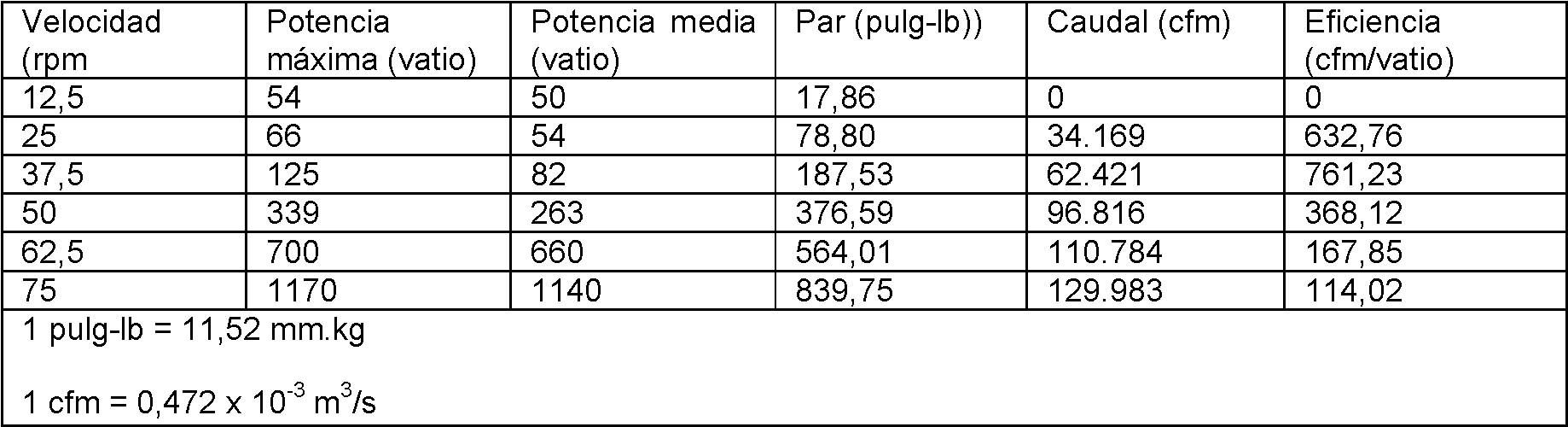
Tabla 2: Ventilador con aletas (70)Table 2: Finned Fan (70)

Naturalmente, pueden obtenerse otros valores mediante la utilización de aletas (70). Además, variaciones adecuadas de las aletas, incluyendo, aunque sin limitación, configuraciones de aleta alternativas, serán evidentes a los expertos en la técnica a la luz de las ideas expuestas en este documento.Naturally, other values can be obtained by using fins (70). Furthermore, suitable variations of the fins, including, but not limited to, alternative fin configurations, will be apparent to those skilled in the art in light of the ideas set forth herein.
Una aleta alternativa meramente ejemplar (170) se representa en las figuras 11-13. Aunque las aletas (170) de este ejemplo se explicarán en el contexto de aspas de ventilador (30, 50, y 800), se apreciará a la luz de las ideas expuestas en este documento que las aletas (170) pueden ser usadas con cualesquiera otras aspas de ventilador adecuadas. A modo de ejemplo solamente, un aspa de ventilador adecuada (800) puede incluir cualquiera de las varias aspas de ventilador descritas en la Solicitud de Patente de Estados Unidos número de serie 11/858.360, titulada "Aspas de ventilador".A merely exemplary alternate fin (170) is depicted in Figures 11-13. Although the fins (170) of this example will be explained in the context of fan blades (30, 50, and 800), it will be appreciated in light of the ideas disclosed herein that the fins (170) can be used with any other suitable fan blades. By way of example only, a suitable fan blade (800) may include any of the several fan blades described in US Patent Application Serial Number 11 / 858,360, entitled "Fan Blades".
La aleta (170) del ejemplo presente incluye un elemento vertical (172). El elemento vertical (172) incluye una superficie interior (174) y una superficie exterior (176). Aunque la superficie interior (174) y la superficie exterior (176) de este ejemplo particular son sustancialmente planas, otras configuraciones adecuadas para la superficie interior (174) y la superficie exterior (176) serán evidentes a los expertos en la técnica a la luz de las ideas expuestas en este documento. Además, como se representa en la figura 13, la superficie exterior (176) incluye una zona de transición redondeada (177) alrededor de su perímetro, adyacente a la superficie interior (174). Sin embargo, tal zona de transición (177) puede tener cualquier otra configuración adecuada, o simplemente puede omitirse.The flap (170) of the present example includes a vertical element (172). The vertical element 172 includes an inner surface 174 and an outer surface 176. Although the inner surface 174 and outer surface 176 of this particular example are substantially flat, other suitable configurations for inner surface 174 and outer surface 176 will be apparent to those skilled in the art in light of the ideas presented in this document. Furthermore, as depicted in Figure 13, the outer surface 176 includes a rounded transition zone 177 around its perimeter, adjacent to the inner surface 174. However, such a transition zone 177 may have any other suitable configuration, or may simply be omitted.
En el ejemplo presente, el perímetro del elemento vertical (172) se define por el borde inferior (178), el borde superior (180) y el borde trasero (182). Como se representa, el borde inferior (178) y el borde superior (180) tienen una curvatura convexa, mientras que el borde trasero (182) es sustancialmente plano. Sin embargo, cualquier borde (178, 180, y/o 182) puede tener cualquier otra configuración adecuada, tal como convexa, cóncava, plana, curvatura compleja, etc, incluyendo sus combinaciones.In the present example, the perimeter of the vertical element 172 is defined by the lower edge 178, the upper edge 180, and the trailing edge 182. As shown, the bottom edge 178 and the top edge 180 have a convex curvature, while the trailing edge 182 is substantially flat. However, any edge (178, 180, and / or 182) can have any other suitable configuration, such as convex, concave, flat, complex curvature, etc., including their combinations.
Cada borde (178, 180, y 182) se une generalmente en una esquina respectiva (184). Así, en el ejemplo presente, el elemento vertical (172) tiene tres esquinas (184). Como se representa, cada esquina (184) está redondeada. Consiguientemente, el término "esquina", en el sentido en que el término se usa en este documento, no deberá interpretarse en el sentido de requerir un ángulo pronunciado. En otros términos, una esquina no tiene que limitarse a un punto o zona donde un par de líneas rectas se unen o intersecan. Aunque en el ejemplo presente el elemento vertical (172) se describe con tres esquinas, se apreciará a la luz de las ideas expuestas en este documento que el elemento vertical (172) puede tener cualquier número adecuado de esquinas (184). A modo de ejemplo solamente, una variación de la aleta (170) puede tener simplemente un borde inferior (178) y un borde superior (180), que se unen en dos esquinas (184). Otras variaciones del elemento vertical (72) serán evidentes a los expertos en la técnica a la luz de las ideas expuestas en este documento.Each edge (178, 180, and 182) is generally joined at a respective corner (184). Thus, in the present example, the vertical element (172) has three corners (184). As depicted, each corner 184 is rounded. Accordingly, the term "corner", in the sense in which the term is used herein, should not be interpreted as requiring a steep angle. In other words, a corner does not have to be limited to a point or area where a pair of straight lines meet or intersect. Although in the present example the vertical element (172) is described with three corners, it will be appreciated in light of the ideas set forth herein that the vertical element (172) can have any suitable number of corners (184). By way of example only, a variation of the flap (170) may simply have a bottom edge (178) and a top edge (180), which are joined at two corners (184). Other variations of the vertical element (72) will be apparent to those skilled in the art in light of the ideas set forth in this document.
La aleta (170) del ejemplo presente también incluye un elemento de montaje de aleta (190), que se extiende de forma sustancialmente perpendicular desde la superficie interior (174) del elemento vertical (172). Como se representa, el elemento de montaje de aleta (190) está configurado de forma similar al elemento de montaje de cubo (12). El elemento de montaje de aleta (190) tiene una superficie superior (192) y una superficie inferior (194), que terminan en el borde de entrada (196) y el borde de salida (198). Además, cada elemento de montaje de aleta (92) incluye una abertura (101) formada a través de la superficie superior (192). En el ejemplo presente, cada abertura (101) está dimensionada para recibir un sujetador (126).The fin (170) of the present example also includes a fin mounting element (190), which extends substantially perpendicularly from the inner surface (174) of the vertical element (172). As shown, the flap mounting element (190) is configured similarly to the hub mounting element (12). The flap mounting element (190) has an upper surface (192) and a lower surface (194), which terminate at the leading edge (196) and the trailing edge (198). In addition, each flap mounting element (92) includes an opening (101) formed through the top surface (192). In the present example, each opening (101) is sized to receive a fastener (126).
El elemento de montaje de aleta (190) está configurado para introducirse en un extremo de un aspa de ventilador, tal como el aspa de ventilador (30 o 50) o cualquier otra aspa de ventilador, de forma similar al elemento de montaje de aleta (90) explicado anteriormente. Los expertos en la técnica apreciarán a la luz de las ideas expuestas en este documento que el elemento de montaje de aletas (190) se puede disponer en varias configuraciones alternativas. La aleta (170) del ejemplo presente también tiene un manguito (200) que se extiende de forma sustancialmente perpendicular desde la superficie interior (174) del elemento vertical (172). Como se representa, se ha dispuesto una zona de transición redondeada (202) alrededor del perímetro de manguito (200), adyacente a la superficie interior (174). Sin embargo, la zona de transición (202) puede tener cualquier otra configuración adecuada, o puede omitirse. Como también se representa, en el manguito (200) se ha formado un rebaje (204) para acomodar y proporcionar holgura para un sujetador (126). Como con otros componentes descritos en este documento, el rebaje (204) se puede variar de cualquier forma adecuada (por ejemplo, proporcionarse como un avellanado, abertura, etc), o puede omitirse.The flap mounting element (190) is configured to be inserted into one end of a fan blade, such as the fan blade (30 or 50) or any other fan blade, similar to the flap mounting element ( 90) explained above. Those skilled in the art will appreciate in light of the ideas set forth herein that the fin mounting element 190 can be arranged in various alternative configurations. The flap (170) in the present example also has a sleeve (200) that extends substantially perpendicularly from the inner surface (174) of the vertical member (172). As shown, a rounded transition zone (202) has been arranged around the sleeve perimeter (200), adjacent to the inner surface (174). However, transition zone 202 may have any other suitable configuration, or may be omitted. As also depicted, a recess (204) has been formed in the sleeve (200) to accommodate and provide clearance for a fastener (126). As with other components described herein, the recess 204 can be varied in any suitable way (eg, provided as a countersink, opening, etc.), or may be omitted.
El manguito (200) del ejemplo presente está configurado para complementar la sección transversal de un aspa de ventilador (800) a la que la aleta (170) está fijada. En particular, la superficie interior (206) del manguito (200) y la superficie exterior (208) del manguito (200) tienen una sección transversal o perfil que es similar a la sección transversal o perfil del aspa de ventilador (800). Por ejemplo, la superficie interior (206) puede estar configurada de tal manera que el manguito (200) proporcione un ajuste apretado con el aspa de ventilador (800), de tal manera que la interfaz entre el manguito (200) y el aspa de ventilador (800) esté sustancialmente libre de intervalos. Igualmente, la superficie interior (206) puede proporcionar un ajuste de interferencia con un aspa de ventilador (800). A la luz de las ideas expuestas en este documento, se apreciará que, en algunas situaciones, un ajuste apretado o ajuste de interferencia entre el manguito (200) y el aspa de ventilador (800) puede reducir el ruido (por ejemplo, el silbido, etc) y/o la probabilidad de intervalos entre el extremo de aspa de ventilador (800) y la aleta (170) que tengan un impacto adverso en el rendimiento o la eficiencia de un ventilador que utiliza el aspa de ventilador (800) y la aleta (170). Alternativamente, pueden obtenerse otros resultados. The sleeve (200) of the present example is configured to complement the cross section of a fan blade (800) to which the flap (170) is attached. In particular, the inner surface (206) of the sleeve (200) and the outer surface (208) of the sleeve (200) have a cross section or profile that is similar to the cross section or profile of the fan blade (800). For example, the inner surface (206) may be configured such that the sleeve (200) provides a tight fit with the fan blade (800), such that the interface between the sleeve (200) and the blade of fan 800 is substantially free of intervals. Likewise, the inner surface (206) can provide an interference fit with a fan blade (800). In light of the ideas set forth in this document, it will be appreciated that, in some situations, a tight fit or interference fit between the sleeve (200) and the fan blade (800) may reduce noise (eg, whistling). , etc.) and / or the probability of intervals between the end of the fan blade (800) and the fin (170) that have an adverse impact on the performance or efficiency of a fan using the fan blade (800) and the fin (170). Alternatively, other results can be obtained.
También se apreciará a la luz de las ideas expuestas en este documento que, en otras versiones, la superficie interior (206) y/o la superficie exterior (208) pueden tener una configuración diferente de la sección transversal del aspa de ventilador (800). Además, el manguito (200) puede estar configurado de tal manera que no se defina por un perímetro continuo. Por ejemplo, se puede disponer uno o varios intervalos (no representados) dentro del perímetro de manguito (200). Otras formas en las que el manguito (200) puede ser modificado, sustituido o complementado serán evidentes a los expertos en la técnica a la luz de las ideas expuestas en este documento.It will also be appreciated in light of the ideas set forth in this document that, in other versions, the inner surface (206) and / or the outer surface (208) may have a different configuration of the cross section of the fan blade (800) . Furthermore, the sleeve 200 can be configured such that it is not defined by a continuous perimeter. For example, one or more intervals (not shown) may be provided within the sleeve perimeter (200). Other ways in which the sleeve 200 can be modified, replaced or supplemented will be apparent to those skilled in the art in light of the ideas set forth herein.
La figura 12 representa un aspa de ventilador (800) con aleta (170) montada, mientras que la figura 13 representa una sección transversal del aspa de ventilador (800) con la aleta (170) montada. De forma análoga al elemento de montaje de cubo (12), el elemento de montaje de aleta (190) encaja ajustadamente contra salientes (no representados) en el aspa de ventilador (800). En el ejemplo presente, el borde superior (180) de la aleta (170) se extiende por encima de la superficie superior (132) del aspa de ventilador (800), además de extenderse más allá del borde de entrada (136). Igualmente, el borde inferior (178) de la aleta (170) se extiende debajo de la superficie inferior (134) del aspa de ventilador (800). El borde trasero (182) de la aleta (170) se extiende más allá del borde de salida (no representado) del aspa de ventilador (800). Naturalmente, las aletas (170) y el aspa de ventilador (800) pueden tener cualesquiera otras dimensiones relativas y/o configuración.Figure 12 depicts a fan blade (800) with flap (170) mounted, while Figure 13 depicts a cross section of the fan blade (800) with flap (170) mounted. Analogously to the hub mounting element (12), the wing mounting element (190) fits snugly against protrusions (not shown) on the fan blade (800). In the present example, the upper edge (180) of the fin (170) extends above the upper surface (132) of the fan blade (800), in addition to extending beyond the inlet edge (136). Similarly, the lower edge (178) of the fin (170) extends below the lower surface (134) of the fan blade (800). The trailing edge (182) of the flap (170) extends beyond the trailing edge (not shown) of the fan blade (800). Naturally, the fins 170 and the fan blade 800 can have any other relative dimensions and / or configuration.
En otra realización (no representada), el elemento de montaje (190) se omite en la aleta (170), de tal manera que la aleta (170) se fija al aspa de ventilador (800) mediante el manguito (200). A modo de ejemplo solamente, se puede disponer una abertura, una ranura u otro elemento (no representado) en el manguito (200) en lugar del rebaje (204), de tal manera que puede insertarse un sujetador (126) a través del elemento en el manguito (200) y engancharse con una abertura formada en el aspa de ventilador (800). En otras realizaciones, la aleta (170) está soldada al aspa de ventilador (800) o fijada al aspa de ventilador (800) con un adhesivo o usando otras estructuras o técnicas. Otras formas en las que la aleta (170) puede fijarse con relación a un aspa de ventilador (800) serán evidentes a los expertos en la técnica a la luz de las ideas expuestas en este documento.In another embodiment (not shown), the mounting element (190) is omitted from the fin (170), such that the fin (170) is fixed to the fan blade (800) by means of the sleeve (200). By way of example only, an opening, slot or other element (not shown) may be provided in the sleeve (200) in place of the recess (204), such that a fastener (126) can be inserted through the element on the sleeve (200) and engage with an opening formed in the fan blade (800). In other embodiments, the flap 170 is welded to the fan blade 800 or attached to the fan blade 800 with an adhesive or using other structures or techniques. Other ways in which the fin 170 can be attached relative to a fan blade 800 will be apparent to those skilled in the art in light of the ideas set forth herein.
También se apreciará a la luz de las ideas expuestas en este documento que la aleta (70) descrita anteriormente puede ser modificada de modo que incluya un manguito (200) o una estructura similar al manguito (200). Igualmente, la aleta (170) puede estar configurada o modificada de manera similar a cualquiera de las variaciones de aleta (70) descritas anteriormente. Además, la aleta (70, 170) puede fijarse al aspa de ventilador (30, 50, o 800) aquí descrita o a cualquier otra aspa de ventilador adecuada.It will also be appreciated in light of the ideas set forth herein that the fin (70) described above can be modified to include a sleeve (200) or a similar structure to the sleeve (200). Similarly, the flap (170) can be configured or modified in a similar way to any of the flap variations (70) described above. Furthermore, the flap (70, 170) can be attached to the fan blade (30, 50, or 800) described herein or to any other suitable fan blade.
La descripción anterior de una o varias realizaciones de la invención se ha presentado a efectos de ilustración y descripción. No tiene la finalidad de ser exhaustiva o de limitar la invención a la forma exacta descrita. Obvias modificaciones o variaciones son posibles a la luz de las ideas anteriores. The foregoing description of one or more embodiments of the invention has been presented for purposes of illustration and description. It is not intended to be exhaustive or to limit the invention to the exact form described. Obvious modifications or variations are possible in light of the above ideas.
Claims (8)
Applications Claiming Priority (2)
| Application Number | Priority Date | Filing Date | Title |
|---|---|---|---|
| US11/860,888 US7934907B2 (en) | 2004-07-21 | 2007-09-25 | Cuffed fan blade modifications |
| PCT/US2008/073677 WO2009042318A1 (en) | 2007-09-25 | 2008-08-20 | Cuffed fan blade modifications |
Publications (1)
| Publication Number | Publication Date |
|---|---|
| ES2750252T3 true ES2750252T3 (en) | 2020-03-25 |
Family
ID=40512152
Family Applications (1)
| Application Number | Title | Priority Date | Filing Date |
|---|---|---|---|
| ES08798241T Active ES2750252T3 (en) | 2007-09-25 | 2008-08-20 | Modifications of fan blade with sleeve |
Country Status (9)
| Country | Link |
|---|---|
| US (1) | US7934907B2 (en) |
| EP (1) | EP2195528B1 (en) |
| CN (1) | CN101842587A (en) |
| AU (1) | AU2008305440B2 (en) |
| BR (1) | BRPI0817304A2 (en) |
| CA (1) | CA2700518C (en) |
| ES (1) | ES2750252T3 (en) |
| MX (1) | MX2010003207A (en) |
| WO (1) | WO2009042318A1 (en) |
Families Citing this family (39)
| Publication number | Priority date | Publication date | Assignee | Title |
|---|---|---|---|---|
| US7252478B2 (en) * | 2004-07-21 | 2007-08-07 | Delta T Corporation | Fan blade modifications |
| EP2118494B1 (en) * | 2007-03-01 | 2019-05-01 | Delta T, LLC | Angled airfoil extension for fan blade |
| US8152453B2 (en) * | 2007-09-17 | 2012-04-10 | Delta T Corporation | Ceiling fan with angled mounting |
| US8147204B2 (en) * | 2007-09-26 | 2012-04-03 | Delta T Corporation | Aerodynamic interface component for fan blade |
| MX2010003208A (en) * | 2007-10-10 | 2010-06-23 | Delta T Corp | Ceiling fan with concentric stationary tube and power-down features. |
| US8672649B2 (en) * | 2007-10-10 | 2014-03-18 | Delta T Corporation | Ceiling fan system with brushless motor |
| US8123479B2 (en) * | 2007-12-19 | 2012-02-28 | Delta T Corporation | Method to minimize oscillation in ceiling fans |
| WO2009100052A1 (en) * | 2008-02-04 | 2009-08-13 | Delta T Corporation | Automatic control system for ceiling fan based on temperature differentials |
| SG10201402822WA (en) | 2008-03-06 | 2014-08-28 | Delta T Corp | Fan control system with sensors |
| AU2009311428B2 (en) * | 2008-10-29 | 2014-04-03 | Delta T, Llc | Multi-part modular airfoil section and method of attachment between parts |
| WO2010111339A1 (en) * | 2009-03-25 | 2010-09-30 | Delta T Corporation | High efficiency ducted fan |
| ES2894354T3 (en) * | 2009-05-04 | 2022-02-14 | Richard A Oleson | Ceiling fan with variable blade pitch |
| EP2483525B1 (en) * | 2009-10-02 | 2020-06-17 | Delta T, LLC | Air fence for fan blade |
| US8770937B2 (en) | 2010-04-22 | 2014-07-08 | Delta T Corporation | Fan blade retention system |
| AU2013209789B2 (en) | 2012-01-20 | 2017-06-29 | Delta T, Llc | Thin airfoil ceiling fan blade |
| US9011099B2 (en) | 2012-06-19 | 2015-04-21 | Skyblade Fan Company | High volume low speed fan |
| US8842000B2 (en) | 2012-07-17 | 2014-09-23 | 4Front Engineered Solutions, Inc. | Fire control systems |
| US10309663B1 (en) | 2013-03-15 | 2019-06-04 | Delta T, Llc | Condensation control system and related method |
| US9874214B2 (en) | 2014-01-28 | 2018-01-23 | 4Front Engineered Solutions, Inc. | Fan with fan blade mounting structure |
| USD732657S1 (en) | 2014-02-27 | 2015-06-23 | Delta T Corporation | Winglet |
| US9856883B1 (en) | 2014-04-14 | 2018-01-02 | Delta T Corporation | Predictive condensation control system and related method |
| CN106574603B (en) * | 2014-08-05 | 2019-12-24 | 瑞安·丘奇 | Structure with rigid winglet adapted to traverse a fluid environment |
| US9726192B2 (en) | 2015-03-31 | 2017-08-08 | Assa Abloy Entrance Systems Ab | Fan blades and associated blade tips |
| US9638209B1 (en) | 2015-07-08 | 2017-05-02 | Van Scott Cogley | Ceiling fan blade attachment |
| EP3203061A1 (en) * | 2016-02-05 | 2017-08-09 | GE Renewable Technologies | Blade for shrouded runner and shrouded runner comprising said blade |
| WO2018019350A1 (en) * | 2016-07-29 | 2018-02-01 | Vestas Wind Systems A/S | Wind turbine blade having a lightning tip receptor |
| EP3491242B1 (en) * | 2016-07-29 | 2020-09-02 | Vestas Wind Systems A/S | Wind turbine blade having a lightning tip receptor |
| US11644046B2 (en) * | 2018-01-05 | 2023-05-09 | Aurora Flight Sciences Corporation | Composite fan blades with integral attachment mechanism |
| TWI655369B (en) * | 2018-01-11 | 2019-04-01 | 建準電機工業股份有限公司 | ceiling fan |
| US11175081B1 (en) | 2018-04-27 | 2021-11-16 | Delta T, Llc | Condensation control system with radiant heating and related method |
| US11022140B2 (en) | 2018-09-04 | 2021-06-01 | Johnson Controls Technology Company | Fan blade winglet |
| US11480191B2 (en) | 2019-09-24 | 2022-10-25 | Delta T, Llc | Blade retention system for overhead fan |
| US12078183B2 (en) * | 2019-09-27 | 2024-09-03 | Panasonic Intellectual Property Management Co., Ltd. | Ceiling fan |
| IT202000005110A1 (en) * | 2020-03-10 | 2021-09-10 | Cofimco Srl | BLADE SYSTEM FOR FANS FOR INDUSTRIAL USE |
| CN111550363B (en) * | 2020-05-22 | 2021-07-30 | 北京博比风电科技有限公司 | Blade tip winglet, wind turbine blade and blade synergy calculation method thereof |
| US20210388841A1 (en) | 2020-06-16 | 2021-12-16 | Delta T, Llc | Ceiling fan with germicidal capabilities |
| CN111608853B (en) * | 2020-07-01 | 2022-01-21 | 上海电气风电集团股份有限公司 | Fan blade |
| WO2023164283A1 (en) * | 2022-02-28 | 2023-08-31 | Delta T, Llc | Fan blades and modifications thereof |
| CN114776389B (en) * | 2022-03-16 | 2024-03-12 | 北京航空航天大学 | Shrouded turbine with rim plate step casing |
Family Cites Families (31)
| Publication number | Priority date | Publication date | Assignee | Title |
|---|---|---|---|---|
| US1041913A (en) | 1909-12-06 | 1912-10-22 | James R Tyson | Aerial propeller. |
| GB100134A (en) | 1915-03-01 | 1917-03-01 | Bbc Brown Boveri & Cie | Improvements in the Manufacture of Blades for Steam and Gas Turbines. |
| US2014032A (en) | 1934-10-24 | 1935-09-10 | Robbins & Myers | An and the like |
| GB946794A (en) | 1961-03-06 | 1964-01-15 | Colchester Woods | Improvements in and relating to axial flow fans or compressors |
| US3171595A (en) * | 1962-03-09 | 1965-03-02 | Westinghouse Electric Corp | Controls for air heating systems |
| GB1119617A (en) | 1966-05-17 | 1968-07-10 | Rolls Royce | Compressor blade for a gas turbine engine |
| DE3017226A1 (en) | 1979-05-12 | 1980-11-20 | Papst Motoren Kg | FAN BLADE |
| US4968216A (en) | 1984-10-12 | 1990-11-06 | The Boeing Company | Two-stage fluid driven turbine |
| US4722608A (en) * | 1985-07-30 | 1988-02-02 | General Signal Corp. | Mixing apparatus |
| US4662823A (en) | 1985-10-28 | 1987-05-05 | Cooke Frank L | Air turbulence blades for ceiling fans |
| GB2198190A (en) | 1986-11-28 | 1988-06-08 | Frank L Cook | Air turbulence blades for ceiling fans |
| DE3819145A1 (en) | 1988-06-04 | 1989-12-14 | Albrecht George Prof D Fischer | Aerodynamically active end plates for aircraft-wing and propeller-blade tips |
| US5152606A (en) * | 1990-07-27 | 1992-10-06 | General Signal Corporation | Mixer impeller shaft attachment apparatus |
| JP3028422B2 (en) | 1990-07-30 | 2000-04-04 | 臼井国際産業株式会社 | Axial fan with centrifugal component |
| US5823480A (en) | 1993-04-05 | 1998-10-20 | La Roche; Ulrich | Wing with a wing grid as the end section |
| US5564901A (en) | 1993-12-14 | 1996-10-15 | The Moore Company | Low noise fan |
| US6161797A (en) | 1996-11-25 | 2000-12-19 | Dugan Air Technologies, Inc. | Method and apparatus for reducing airplane noise |
| US5725355A (en) | 1996-12-10 | 1998-03-10 | General Electric Company | Adhesive bonded fan blade |
| US6884034B1 (en) | 1998-04-07 | 2005-04-26 | University Of Central Florida | Enhancements to high efficiency ceiling fan |
| US6039541A (en) | 1998-04-07 | 2000-03-21 | University Of Central Florida | High efficiency ceiling fan |
| US6244821B1 (en) | 1999-02-19 | 2001-06-12 | Mechanization Systems Company, Inc. | Low speed cooling fan |
| US6565320B1 (en) | 2000-11-13 | 2003-05-20 | Borgwarner, Inc. | Molded cooling fan |
| US6517315B2 (en) | 2001-05-29 | 2003-02-11 | Hewlett-Packard Company | Enhanced performance fan with the use of winglets |
| US6626640B2 (en) | 2001-11-19 | 2003-09-30 | Durmitor Inc. | Fan with reduced noise |
| US7008192B2 (en) | 2002-05-23 | 2006-03-07 | Minka Lighting, Inc. | Ceiling fan blade attachment assembly |
| US6719533B2 (en) | 2002-07-11 | 2004-04-13 | Hunter Fan Company | High efficiency ceiling fan |
| US6939108B2 (en) | 2003-01-06 | 2005-09-06 | Mechanization Systems Company, Inc. | Cooling fan with reinforced blade |
| MX2007000821A (en) | 2004-07-21 | 2007-09-11 | Delta T Corp | Fan blades and modifications. |
| US7252478B2 (en) | 2004-07-21 | 2007-08-07 | Delta T Corporation | Fan blade modifications |
| US8079823B2 (en) | 2004-07-21 | 2011-12-20 | Delta T Corporation | Fan blades |
| US7284960B2 (en) | 2004-07-21 | 2007-10-23 | Delta T Corporation | Fan blades |
-
2007
- 2007-09-25 US US11/860,888 patent/US7934907B2/en active Active
-
2008
- 2008-08-20 BR BRPI0817304-4A patent/BRPI0817304A2/en not_active Application Discontinuation
- 2008-08-20 MX MX2010003207A patent/MX2010003207A/en active IP Right Grant
- 2008-08-20 AU AU2008305440A patent/AU2008305440B2/en active Active
- 2008-08-20 CA CA2700518A patent/CA2700518C/en active Active
- 2008-08-20 ES ES08798241T patent/ES2750252T3/en active Active
- 2008-08-20 EP EP08798241.9A patent/EP2195528B1/en active Active
- 2008-08-20 WO PCT/US2008/073677 patent/WO2009042318A1/en active Application Filing
- 2008-08-20 CN CN200880113655A patent/CN101842587A/en active Pending
Also Published As
| Publication number | Publication date |
|---|---|
| CN101842587A (en) | 2010-09-22 |
| MX2010003207A (en) | 2010-06-23 |
| US20080014090A1 (en) | 2008-01-17 |
| CA2700518C (en) | 2016-01-19 |
| EP2195528B1 (en) | 2019-08-07 |
| CA2700518A1 (en) | 2009-04-02 |
| US7934907B2 (en) | 2011-05-03 |
| EP2195528A1 (en) | 2010-06-16 |
| BRPI0817304A2 (en) | 2015-06-16 |
| EP2195528A4 (en) | 2017-05-17 |
| AU2008305440A1 (en) | 2009-04-02 |
| WO2009042318A1 (en) | 2009-04-02 |
| AU2008305440B2 (en) | 2013-08-15 |
Similar Documents
| Publication | Publication Date | Title |
|---|---|---|
| ES2750252T3 (en) | Modifications of fan blade with sleeve | |
| ES2689689T3 (en) | Fan blade | |
| ES2631252T3 (en) | Fan blades | |
| US8079823B2 (en) | Fan blades | |
| KR101297469B1 (en) | Fan blades and modifications | |
| CN110036209B (en) | Propeller fan | |
| CA2719755C (en) | Fan blades | |
| TWM484731U (en) | A fan apparatus |