EP4583591A2 - Energiesparbetrieb bei der trägeraggregation - Google Patents
Energiesparbetrieb bei der trägeraggregation Download PDFInfo
- Publication number
- EP4583591A2 EP4583591A2 EP25164180.9A EP25164180A EP4583591A2 EP 4583591 A2 EP4583591 A2 EP 4583591A2 EP 25164180 A EP25164180 A EP 25164180A EP 4583591 A2 EP4583591 A2 EP 4583591A2
- Authority
- EP
- European Patent Office
- Prior art keywords
- wireless device
- cell
- bwp
- pdcch
- base station
- Prior art date
- Legal status (The legal status is an assumption and is not a legal conclusion. Google has not performed a legal analysis and makes no representation as to the accuracy of the status listed.)
- Pending
Links
Images













Classifications
-
- H—ELECTRICITY
- H04—ELECTRIC COMMUNICATION TECHNIQUE
- H04W—WIRELESS COMMUNICATION NETWORKS
- H04W52/00—Power management, e.g. Transmission Power Control [TPC] or power classes
- H04W52/02—Power saving arrangements
- H04W52/0209—Power saving arrangements in terminal devices
- H04W52/0212—Power saving arrangements in terminal devices managed by the network, e.g. network or access point is leader and terminal is follower
- H04W52/0216—Power saving arrangements in terminal devices managed by the network, e.g. network or access point is leader and terminal is follower using a pre-established activity schedule, e.g. traffic indication frame
-
- H—ELECTRICITY
- H04—ELECTRIC COMMUNICATION TECHNIQUE
- H04W—WIRELESS COMMUNICATION NETWORKS
- H04W52/00—Power management, e.g. Transmission Power Control [TPC] or power classes
- H04W52/02—Power saving arrangements
- H04W52/0209—Power saving arrangements in terminal devices
- H04W52/0212—Power saving arrangements in terminal devices managed by the network, e.g. network or access point is leader and terminal is follower
- H04W52/0219—Power saving arrangements in terminal devices managed by the network, e.g. network or access point is leader and terminal is follower where the power saving management affects multiple terminals
-
- H—ELECTRICITY
- H04—ELECTRIC COMMUNICATION TECHNIQUE
- H04W—WIRELESS COMMUNICATION NETWORKS
- H04W52/00—Power management, e.g. Transmission Power Control [TPC] or power classes
- H04W52/02—Power saving arrangements
- H04W52/0209—Power saving arrangements in terminal devices
- H04W52/0225—Power saving arrangements in terminal devices using monitoring of external events, e.g. the presence of a signal
- H04W52/0229—Power saving arrangements in terminal devices using monitoring of external events, e.g. the presence of a signal where the received signal is a wanted signal
-
- H—ELECTRICITY
- H04—ELECTRIC COMMUNICATION TECHNIQUE
- H04W—WIRELESS COMMUNICATION NETWORKS
- H04W52/00—Power management, e.g. Transmission Power Control [TPC] or power classes
- H04W52/02—Power saving arrangements
- H04W52/0209—Power saving arrangements in terminal devices
- H04W52/0225—Power saving arrangements in terminal devices using monitoring of external events, e.g. the presence of a signal
- H04W52/0229—Power saving arrangements in terminal devices using monitoring of external events, e.g. the presence of a signal where the received signal is a wanted signal
- H04W52/0235—Power saving arrangements in terminal devices using monitoring of external events, e.g. the presence of a signal where the received signal is a wanted signal where the received signal is a power saving command
-
- H—ELECTRICITY
- H04—ELECTRIC COMMUNICATION TECHNIQUE
- H04W—WIRELESS COMMUNICATION NETWORKS
- H04W52/00—Power management, e.g. Transmission Power Control [TPC] or power classes
- H04W52/02—Power saving arrangements
- H04W52/0209—Power saving arrangements in terminal devices
- H04W52/0261—Power saving arrangements in terminal devices managing power supply demand, e.g. depending on battery level
- H04W52/0274—Power saving arrangements in terminal devices managing power supply demand, e.g. depending on battery level by switching on or off the equipment or parts thereof
- H04W52/028—Power saving arrangements in terminal devices managing power supply demand, e.g. depending on battery level by switching on or off the equipment or parts thereof switching on or off only a part of the equipment circuit blocks
-
- H—ELECTRICITY
- H04—ELECTRIC COMMUNICATION TECHNIQUE
- H04W—WIRELESS COMMUNICATION NETWORKS
- H04W72/00—Local resource management
- H04W72/04—Wireless resource allocation
- H04W72/044—Wireless resource allocation based on the type of the allocated resource
- H04W72/0453—Resources in frequency domain, e.g. a carrier in FDMA
-
- H—ELECTRICITY
- H04—ELECTRIC COMMUNICATION TECHNIQUE
- H04W—WIRELESS COMMUNICATION NETWORKS
- H04W72/00—Local resource management
- H04W72/20—Control channels or signalling for resource management
- H04W72/23—Control channels or signalling for resource management in the downlink direction of a wireless link, i.e. towards a terminal
- H04W72/231—Control channels or signalling for resource management in the downlink direction of a wireless link, i.e. towards a terminal the control data signalling from the layers above the physical layer, e.g. RRC or MAC-CE signalling
-
- H—ELECTRICITY
- H04—ELECTRIC COMMUNICATION TECHNIQUE
- H04W—WIRELESS COMMUNICATION NETWORKS
- H04W72/00—Local resource management
- H04W72/20—Control channels or signalling for resource management
- H04W72/23—Control channels or signalling for resource management in the downlink direction of a wireless link, i.e. towards a terminal
- H04W72/232—Control channels or signalling for resource management in the downlink direction of a wireless link, i.e. towards a terminal the control data signalling from the physical layer, e.g. DCI signalling
-
- H—ELECTRICITY
- H04—ELECTRIC COMMUNICATION TECHNIQUE
- H04W—WIRELESS COMMUNICATION NETWORKS
- H04W76/00—Connection management
- H04W76/20—Manipulation of established connections
-
- Y—GENERAL TAGGING OF NEW TECHNOLOGICAL DEVELOPMENTS; GENERAL TAGGING OF CROSS-SECTIONAL TECHNOLOGIES SPANNING OVER SEVERAL SECTIONS OF THE IPC; TECHNICAL SUBJECTS COVERED BY FORMER USPC CROSS-REFERENCE ART COLLECTIONS [XRACs] AND DIGESTS
- Y02—TECHNOLOGIES OR APPLICATIONS FOR MITIGATION OR ADAPTATION AGAINST CLIMATE CHANGE
- Y02D—CLIMATE CHANGE MITIGATION TECHNOLOGIES IN INFORMATION AND COMMUNICATION TECHNOLOGIES [ICT], I.E. INFORMATION AND COMMUNICATION TECHNOLOGIES AIMING AT THE REDUCTION OF THEIR OWN ENERGY USE
- Y02D30/00—Reducing energy consumption in communication networks
- Y02D30/70—Reducing energy consumption in communication networks in wireless communication networks
Definitions
- This application relates to the field of wireless communication systems such as 4G communication systems (e.g., LTE), 5G communication systems, other communication systems compatible with 4G and/or 5G communication systems, and related methods, systems and apparatuses.
- Embodiments may be configured to operate as needed.
- the disclosed mechanism may be performed when certain criteria are met, for example, in a wireless device, a base station, a radio environment, a network, a combination of the above, and/or the like.
- Example criteria may be based, at least in part, on for example, wireless device or network node configurations, traffic load, initial system set up, packet sizes, traffic characteristics, a combination of the above, and/or the like.
- various example embodiments may be applied. Therefore, it may be possible to implement example embodiments that selectively implement disclosed protocols.
- a and B are sets and every element of A is an element of B, A is called a subset of B.
- A is called a subset of B.
- possible subsets of B ⁇ cell1, cell2 ⁇ are: ⁇ cell1 ⁇ , ⁇ cell2 ⁇ , and ⁇ cell1, cell2 ⁇ .
- the phrase "based on” is indicative that the phrase following the term "based on” is an example of one of a multitude of suitable possibilities that may, or may not, be employed to one or more of the various embodiments.
- modules may be implemented as modules.
- a module is defined here as an element that performs a defined function and has a defined interface to other elements.
- the modules described in this disclosure may be implemented in hardware, software in combination with hardware, firmware, wetware (e.g. hardware with a biological element) or a combination thereof, which may be behaviorally equivalent.
- modules may be implemented as a software routine written in a computer language configured to be executed by a hardware machine (such as C, C++, Fortran, Java, Basic, Matlab or the like) or a modeling/simulation program such as Simulink, Stateflow, GNU Script, or LabVIEWMathScript.
- modules may be possible to implement modules using physical hardware that incorporates discrete or programmable analog, digital and/or quantum hardware.
- programmable hardware comprise: computers, microcontrollers, microprocessors, application-specific integrated circuits (ASICs); field programmable gate arrays (FPGAs); and complex programmable logic devices (CPLDs).
- Computers, microcontrollers and microprocessors are programmed using languages such as assembly, C, C++ or the like.
- FPGAs, ASICs and CPLDs are often programmed using hardware description languages (HDL) such as VHSIC hardware description language (VHDL) or Verilog that configure connections between internal hardware modules with lesser functionality on a programmable device.
- HDL hardware description languages
- VHDL VHSIC hardware description language
- Verilog Verilog
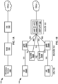
- the CN 102 may provide the wireless device 106 with an interface to one or more data networks (DNs), such as public DNs (e.g., the Internet), private DNs, and/or intra-operator DNs.
- DNs data networks
- the CN 102 may set up end-to-end connections between the wireless device 106 and the one or more DNs, authenticate the wireless device 106, and provide charging functionality.
- the RAN 104 may connect the CN 102 to the wireless device 106 through radio communications over an air interface. As part of the radio communications, the RAN 104 may provide scheduling, radio resource management, and retransmission protocols.
- the communication direction from the RAN 104 to the wireless device 106 over the air interface is known as the downlink and the communication direction from the wireless device 106 to the RAN 104 over the air interface is known as the uplink.
- Downlink transmissions may be separated from uplink transmissions using frequency division duplexing (FDD), time-division duplexing (TDD), and/or some combination of the two duplexing techniques.
- FDD frequency division duplexing
- TDD time-division duplexing
- wireless device may be used throughout this disclosure to refer to and encompass any mobile device or fixed (non-mobile) device for which wireless communication is needed or usable.
- a wireless device may be a telephone, smart phone, tablet, computer, laptop, sensor, meter, wearable device, Internet of Things (IoT) device, vehicle road side unit (RSU), relay node, automobile, and/or any combination thereof.
- IoT Internet of Things
- RSU vehicle road side unit
- the term wireless device encompasses other terminology, including user equipment (UE), user terminal (UT), access terminal (AT), mobile station, handset, wireless transmit and receive unit (WTRU), and/or wireless communication device.
- UE user equipment
- UT user terminal
- AT access terminal
- WTRU wireless transmit and receive unit
- the RAN 104 may include one or more base stations (not shown).
- the term base station may be used throughout this disclosure to refer to and encompass a Node B (associated with UMTS and/or 3G standards), an Evolved Node B (eNB, associated with E-UTRA and/or 4G standards), a remote radio head (RRH), a baseband processing unit coupled to one or more RRHs, a repeater node or relay node used to extend the coverage area of a donor node, a Next Generation Evolved Node B (ng-eNB), a Generation Node B (gNB, associated with NR and/or 5G standards), an access point (AP, associated with, for example, WiFi or any other suitable wireless communication standard), and/or any combination thereof.
- a base station may comprise at least one gNB Central Unit (gNB-CU) and at least one a gNB Distributed Unit (gNB-DU).
- one or more of the base stations in the RAN 104 may be implemented as a sectored site with more or less than three sectors.
- One or more of the base stations in the RAN 104 may be implemented as an access point, as a baseband processing unit coupled to several remote radio heads (RRHs), and/or as a repeater or relay node used to extend the coverage area of a donor node.
- RRHs remote radio heads
- a baseband processing unit coupled to RRHs may be part of a centralized or cloud RAN architecture, where the baseband processing unit may be either centralized in a pool of baseband processing units or virtualized.
- the 5G-CN 152 includes an Access and Mobility Management Function (AMF) 158A and a User Plane Function (UPF) 158B, which are shown as one component AMF/UPF 158 in FIG. 1B for ease of illustration.
- AMF Access and Mobility Management Function
- UPF User Plane Function
- the UPF 158B may serve as a gateway between the NG-RAN 154 and the one or more DNs.
- the MACs 212 and 222 may be configured to perform error correction through Hybrid Automatic Repeat Request (HARQ) (e.g., one HARQ entity per carrier in case of Carrier Aggregation (CA)), priority handling between logical channels of the UE 210 by means of logical channel prioritization, and/or padding.
- HARQ Hybrid Automatic Repeat Request
- the MACs 212 and 222 may support one or more numerologies and/or transmission timings. In an example, mapping restrictions in a logical channel prioritization may control which numerology and/or transmission timing a logical channel may use.
- the MACs 212 and 222 may provide logical channels as a service to the RLCs 213 and 223.
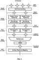
- FIG. 4A illustrates an example downlink data flow through the NR user plane protocol stack.
- FIG. 4A illustrates a downlink data flow of three IP packets ( n , n+1 , and m ) through the NR user plane protocol stack to generate two TBs at the gNB 220.
- An uplink data flow through the NR user plane protocol stack may be similar to the downlink data flow depicted in FIG. 4A .
- the downlink data flow of FIG. 4A begins when SDAP 225 receives the three IP packets from one or more QoS flows and maps the three packets to radio bearers.
- the SDAP 225 maps IP packets n and n+1 to a first radio bearer 402 and maps IP packet m to a second radio bearer 404.
- An SDAP header (labeled with an "H" in FIG. 4A ) is added to an IP packet.
- the data unit from/to a higher protocol layer is referred to as a service data unit (SDU) of the lower protocol layer and the data unit to/from a lower protocol layer is referred to as a protocol data unit (PDU) of the higher protocol layer.
- SDU service data unit
- PDU protocol data unit
- the data unit from the SDAP 225 is an SDU of lower protocol layer PDCP 224 and is a PDU of the SDAP 225.
- the remaining protocol layers in FIG. 4A may perform their associated functionality (e.g., with respect to FIG. 3 ), add corresponding headers, and forward their respective outputs to the next lower layer.
- the PDCP 224 may perform IP-header compression and ciphering and forward its output to the RLC 223.
- the RLC 223 may optionally perform segmentation (e.g., as shown for IP packet m in FIG. 4A ) and forward its output to the MAC 222.
- the MAC 222 may multiplex a number of RLC PDUs and may attach a MAC subheader to an RLC PDU to form a transport block.
- the MAC subheaders may be distributed across the MAC PDU, as illustrated in FIG. 4A .
- the MAC subheaders may be entirely located at the beginning of the MAC PDU.
- the NR MAC PDU structure may reduce processing time and associated latency because the MAC PDU subheaders may be computed before the full MAC PDU is assembled.
- FIG. 4B illustrates an example format of a MAC subheader in a MAC PDU.
- the MAC subheader includes: an SDU length field for indicating the length (e.g., in bytes) of the MAC SDU to which the MAC subheader corresponds; a logical channel identifier (LCID) field for identifying the logical channel from which the MAC SDU originated to aid in the demultiplexing process; a flag (F) for indicating the size of the SDU length field; and a reserved bit (R) field for future use.
- SDU length field for indicating the length (e.g., in bytes) of the MAC SDU to which the MAC subheader corresponds
- LCID logical channel identifier
- F flag
- R reserved bit
- Example MAC CEs include: scheduling-related MAC CEs, such as buffer status reports and power headroom reports; activation/deactivation MAC CEs, such as those for activation/deactivation of PDCP duplication detection, channel state information (CSI) reporting, sounding reference signal (SRS) transmission, and prior configured components; discontinuous reception (DRX) related MAC CEs; timing advance MAC CEs; and random access related MAC CEs.
- a MAC CE may be preceded by a MAC subheader with a similar format as described for MAC SDUs and may be identified with a reserved value in the LCID field that indicates the type of control information included in the MAC CE.
- logical channels, transport channels, and physical channels are first described as well as a mapping between the channel types.
- One or more of the channels may be used to carry out functions associated with the NR control plane protocol stack described later below.
- FIG. 5A and FIG. 5B illustrate, for downlink and uplink respectively, a mapping between logical channels, transport channels, and physical channels.
- Information is passed through channels between the RLC, the MAC, and the PHY of the NR protocol stack.
- a logical channel may be used between the RLC and the MAC and may be classified as a control channel that carries control and configuration information in the NR control plane or as a traffic channel that carries data in the NR user plane.
- a logical channel may be classified as a dedicated logical channel that is dedicated to a specific UE or as a common logical channel that may be used by more than one UE.
- a logical channel may also be defined by the type of information it carries.
- the set of logical channels defined by NR include, for example:
- Transport channels are used between the MAC and PHY layers and may be defined by how the information they carry is transmitted over the air interface.
- the set of transport channels defined by NR include, for example:
- the PHY may use physical channels to pass information between processing levels of the PHY.
- a physical channel may have an associated set of time-frequency resources for carrying the information of one or more transport channels.
- the PHY may generate control information to support the low-level operation of the PHY and provide the control information to the lower levels of the PHY via physical control channels, known as L1/L2 control channels.
- the set of physical channels and physical control channels defined by NR include, for example:
- the physical layer Similar to the physical control channels, the physical layer generates physical signals to support the low-level operation of the physical layer.
- the physical layer signals defined by NR include: primary synchronization signals (PSS), secondary synchronization signals (SSS), channel state information reference signals (CSI-RS), demodulation reference signals (DMRS), sounding reference signals (SRS), and phase-tracking reference signals (PT-RS). These physical layer signals will be described in greater detail below.
- FIG. 2B illustrates an example NR control plane protocol stack.
- the NR control plane protocol stack may use the same/similar first four protocol layers as the example NR user plane protocol stack. These four protocol layers include the PHYs 211 and 221, the MACs 212 and 222, the RLCs 213 and 223, and the PDCPs 214 and 224.
- the NR control plane stack has radio resource controls (RRCs) 216 and 226 and NAS protocols 217 and 237 at the top of the NR control plane protocol stack.
- RRCs radio resource controls
- the NAS protocols 217 and 237 may provide control plane functionality between the UE 210 and the AMF 230 (e.g., the AMF 158A) or, more generally, between the UE 210 and the CN.
- the NAS protocols 217 and 237 may provide control plane functionality between the UE 210 and the AMF 230 via signaling messages, referred to as NAS messages. There is no direct path between the UE 210 and the AMF 230 through which the NAS messages can be transported.
- the NAS messages may be transported using the AS of the Uu and NG interfaces.
- NAS protocols 217 and 237 may provide control plane functionality such as authentication, security, connection setup, mobility management, and session management.
- the RRCs 216 and 226 may provide control plane functionality between the UE 210 and the gNB 220 or, more generally, between the UE 210 and the RAN.
- the RRCs 216 and 226 may provide control plane functionality between the UE 210 and the gNB 220 via signaling messages, referred to as RRC messages.
- RRC messages may be transmitted between the UE 210 and the RAN using signaling radio bearers and the same/similar PDCP, RLC, MAC, and PHY protocol layers.
- the MAC may multiplex control-plane and user-plane data into the same transport block (TB).
- the RRCs 216 and 226 may provide control plane functionality such as: broadcast of system information related to AS and NAS; paging initiated by the CN or the RAN; establishment, maintenance and release of an RRC connection between the UE 210 and the RAN; security functions including key management; establishment, configuration, maintenance and release of signaling radio bearers and data radio bearers; mobility functions; QoS management functions; the UE measurement reporting and control of the reporting; detection of and recovery from radio link failure (RLF); and/or NAS message transfer.
- RRCs 216 and 226 may establish an RRC context, which may involve configuring parameters for communication between the UE 210 and the RAN.
- the UE has an established RRC context and may have at least one RRC connection with a base station.
- the base station may be similar to one of the one or more base stations included in the RAN 104 depicted in FIG. 1A , one of the gNBs 160 or ng-eNBs 162 depicted in FIG. 1B , the gNB 220 depicted in FIG. 2A and FIG. 2B , or any other base station described in the present disclosure.
- the base station with which the UE is connected may have the RRC context for the UE.
- the RRC context referred to as the UE context, may comprise parameters for communication between the UE and the base station.
- These parameters may include, for example: one or more AS contexts; one or more radio link configuration parameters; bearer configuration information (e.g., relating to a data radio bearer, signaling radio bearer, logical channel, QoS flow, and/or PDU session); security information; and/or PHY, MAC, RLC, PDCP, and/or SDAP layer configuration information.
- bearer configuration information e.g., relating to a data radio bearer, signaling radio bearer, logical channel, QoS flow, and/or PDU session
- security information e.g., relating to a data radio bearer, signaling radio bearer, logical channel, QoS flow, and/or PDU session
- PHY e.g., MAC, RLC, PDCP, and/or SDAP layer configuration information
- the RAN e.g., the RAN 104 or the NG-RAN 154
- the UE may measure the signal levels (e.g., reference signal levels) from a serving cell
- the UE's serving base station may request a handover to a cell of one of the neighboring base stations based on the reported measurements.
- the RRC state may transition from RRC connected 602 to RRC idle 604 through a connection release procedure 608 or to RRC inactive 606 through a connection inactivation procedure 610.
- RRC idle 604 an RRC context may not be established for the UE.
- the UE may not have an RRC connection with the base station.
- the UE may be in a sleep state for the majority of the time (e.g., to conserve battery power).
- the UE may wake up periodically (e.g., once in every discontinuous reception cycle) to monitor for paging messages from the RAN.
- Mobility of the UE may be managed by the UE through a procedure known as cell reselection.
- the RRC state may transition from RRC idle 604 to RRC connected 602 through a connection establishment procedure 612, which may involve a random access procedure as discussed in greater detail below.
- RRC inactive 606 the RRC context previously established is maintained in the UE and the base station. This allows for a fast transition to RRC connected 602 with reduced signaling overhead as compared to the transition from RRC idle 604 to RRC connected 602.
- the UE While in RRC inactive 606, the UE may be in a sleep state and mobility of the UE may be managed by the UE through cell reselection.
- the RRC state may transition from RRC inactive 606 to RRC connected 602 through a connection resume procedure 614 or to RRC idle 604 though a connection release procedure 616 that may be the same as or similar to connection release procedure 608.
- An RRC state may be associated with a mobility management mechanism.
- RRC idle 604 and RRC inactive 606 mobility is managed by the UE through cell reselection.
- the purpose of mobility management in RRC idle 604 and RRC inactive 606 is to allow the network to be able to notify the UE of an event via a paging message without having to broadcast the paging message over the entire mobile communications network.
- the mobility management mechanism used in RRC idle 604 and RRC inactive 606 may allow the network to track the UE on a cell-group level so that the paging message may be broadcast over the cells of the cell group that the UE currently resides within instead of the entire mobile communication network.
- the mobility management mechanisms for RRC idle 604 and RRC inactive 606 track the UE on a cell-group level. They may do so using different granularities of grouping. For example, there may be three levels of cell-grouping granularity: individual cells; cells within a RAN area identified by a RAN area identifier (RAI); and cells within a group of RAN areas, referred to as a tracking area and identified by a tracking area identifier (TAI).
- RAI RAN area identifier
- TAI tracking area and identified by a tracking area identifier
- Tracking areas may be used to track the UE at the CN level.
- the CN e.g., the CN 102 or the 5G-CN 152 may provide the UE with a list of TAIs associated with a UE registration area. If the UE moves, through cell reselection, to a cell associated with a TAI not included in the list of TAIs associated with the UE registration area, the UE may perform a registration update with the CN to allow the CN to update the UE's location and provide the UE with a new the UE registration area.
- RAN areas may be used to track the UE at the RAN level.
- the UE may be assigned a RAN notification area.
- a RAN notification area may comprise one or more cell identities, a list of RAIs, or a list of TAIs.
- a base station may belong to one or more RAN notification areas.
- a cell may belong to one or more RAN notification areas. If the UE moves, through cell reselection, to a cell not included in the RAN notification area assigned to the UE, the UE may perform a notification area update with the RAN to update the UE's RAN notification area.
- a base station storing an RRC context for a UE or a last serving base station of the UE may be referred to as an anchor base station.
- An anchor base station may maintain an RRC context for the UE at least during a period of time that the UE stays in a RAN notification area of the anchor base station and/or during a period of time that the UE stays in RRC inactive 606.
- a base station may configure a UE with one or more control resource sets (CORESETs) for at least one search space.
- CORESETs control resource sets
- a search space is a set of locations in the time and frequency domains where the UE may find control information.
- the search space may be a UE-specific search space or a common search space (potentially usable by a plurality of UEs).
- a base station may configure a UE with a common search space, on a PCell or on a primary secondary cell (PSCell), in an active downlink BWP.
- the UE may start the time window one or more symbols after a last symbol of the preamble (e.g., at a first PDCCH occasion from an end of a preamble transmission).
- the one or more symbols may be determined based on a numerology.
- the PDCCH may be in a common search space (e.g., a Type1-PDCCH common search space) configured by an RRC message.
- the UE may identify the RAR based on a Radio Network Temporary Identifier (RNTI). RNTIs may be used depending on one or more events initiating the random access procedure.
- the UE may use random access RNTI (RA-RNTI).
- the RA-RNTI may be associated with PRACH occasions in which the UE transmits a preamble.
- the UE may determine the RA-RNTI based on: an OFDM symbol index; a slot index; a frequency domain index; and/or a UL carrier indicator of the PRACH occasions.
- the UE may transmit the Msg 3 1313 in response to a successful reception of the Msg 2 1312 (e.g., using resources identified in the Msg 2 1312).
- the Msg 3 1313 may be used for contention resolution in, for example, the contention-based random access procedure illustrated in FIG. 13A .
- a plurality of UEs may transmit a same preamble to a base station and the base station may provide an RAR that corresponds to a UE. Collisions may occur if the plurality of UEs interpret the RAR as corresponding to themselves.
- Contention resolution (e.g., using the Msg 3 1313 and the Msg 4 1314) may be used to increase the likelihood that the UE does not incorrectly use an identity of another the UE.
- the UE may include a device identifier in the Msg 3 1313 (e.g., a C-RNTI if assigned, a TC-RNTI included in the Msg 2 1312, and/or any other suitable identifier).
- the Msg 4 1314 may be received after or in response to the transmitting of the Msg 3 1313. If a C-RNTI was included in the Msg 3 1313, the base station will address the UE on the PDCCH using the C-RNTI. If the UE's unique C-RNTI is detected on the PDCCH, the random access procedure is determined to be successfully completed. If a TC-RNTI is included in the Msg 3 1313 (e.g., if the UE is in an RRC_IDLE state or not otherwise connected to the base station), Msg 4 1314 will be received using a DL-SCH associated with the TC-RNTI.
- the UE may be configured with a supplementary uplink (SUL) carrier and a normal uplink (NUL) carrier.
- An initial access (e.g., random access procedure) may be supported in an uplink carrier.
- a base station may configure the UE with two separate RACH configurations: one for an SUL carrier and the other for an NUL carrier.
- the network may indicate which carrier to use (NUL or SUL).
- the UE may determine the SUL carrier, for example, if a measured quality of one or more reference signals is lower than a broadcast threshold.
- Uplink transmissions of the random access procedure (e.g., the Msg 1 1311 and/or the Msg 3 1313) may remain on the selected carrier.
- the UE may switch an uplink carrier during the random access procedure (e.g., between the Msg 1 1311 and the Msg 3 1313) in one or more cases. For example, the UE may determine and/or switch an uplink carrier for the Msg 1 1311 and/or the Msg 3 1313 based on a channel clear assessment (e.g., a listen-before-talk).
- a channel clear assessment e.g., a listen-before-talk.
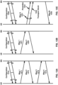
- FIG. 13B illustrates a two-step contention-free random access procedure. Similar to the four-step contention-based random access procedure illustrated in FIG. 13A , a base station may, prior to initiation of the procedure, transmit a configuration message 1320 to the UE.
- the configuration message 1320 may be analogous in some respects to the configuration message 1310.
- the procedure illustrated in FIG. 13B comprises transmission of two messages: a Msg 1 1321 and a Msg 2 1322.
- the Msg 1 1321 and the Msg 2 1322 may be analogous in some respects to the Msg 1 1311 and a Msg 2 1312 illustrated in FIG. 13A , respectively.
- the contention-free random access procedure may not include messages analogous to the Msg 3 1313 and/or the Msg 4 1314.
- the contention-free random access procedure illustrated in FIG. 13B may be initiated for a beam failure recovery, other SI request, SCell addition, and/or handover.
- a base station may indicate or assign to the UE the preamble to be used for the Msg 1 1321.
- the UE may receive, from the base station via PDCCH and/or RRC, an indication of a preamble (e.g., ra-PreambleIndex).
- the UE may start a time window (e.g., ra-ResponseWindow) to monitor a PDCCH for the RAR.
- a time window e.g., ra-ResponseWindow
- the base station may configure the UE with a separate time window and/or a separate PDCCH in a search space indicated by an RRC message (e.g., recoverySearchSpaceId).
- the UE may monitor for a PDCCH transmission addressed to a Cell RNTI (C-RNTI) on the search space.
- C-RNTI Cell RNTI
- the UE may determine that a random access procedure successfully completes after or in response to transmission of Msg 1 1321 and reception of a corresponding Msg 2 1322.
- the UE may determine that a random access procedure successfully completes, for example, if a PDCCH transmission is addressed to a C-RNTI.
- the UE may determine that a random access procedure successfully completes, for example, if the UE receives an RAR comprising a preamble identifier corresponding to a preamble transmitted by the UE and/or the RAR comprises a MAC sub-PDU with the preamble identifier.
- the UE may determine the response as an indication of an acknowledgement for an SI request.
- FIG. 13C illustrates another two-step random access procedure. Similar to the random access procedures illustrated in FIGS. 13A and 13B , a base station may, prior to initiation of the procedure, transmit a configuration message 1330 to the UE.
- the configuration message 1330 may be analogous in some respects to the configuration message 1310 and/or the configuration message 1320.
- the procedure illustrated in FIG. 13C comprises transmission of two messages: a Msg A 1331 and a Msg B 1332.
- Msg A 1331 may be transmitted in an uplink transmission by the UE.
- Msg A 1331 may comprise one or more transmissions of a preamble 1341 and/or one or more transmissions of a transport block 1342.
- the transport block 1342 may comprise contents that are similar and/or equivalent to the contents of the Msg 3 1313 illustrated in FIG. 13A .
- the transport block 1342 may comprise UCI (e.g., an SR, a HARQ ACK/NACK, and/or the like).
- the UE may receive the Msg B 1332 after or in response to transmitting the Msg A 1331.
- the Msg B 1332 may comprise contents that are similar and/or equivalent to the contents of the Msg 2 1312 (e.g., an RAR) illustrated in FIGS. 13A and 13B and/or the Msg 4 1314 illustrated in FIG. 13A .
- the UE may initiate the two-step random access procedure in FIG. 13C for licensed spectrum and/or unlicensed spectrum.
- the UE may determine, based on one or more factors, whether to initiate the two-step random access procedure.
- the one or more factors may be: a radio access technology in use (e.g., LTE, NR, and/or the like); whether the UE has valid TA or not; a cell size; the UE's RRC state; a type of spectrum (e.g., licensed vs. unlicensed); and/or any other suitable factors.
- the transport block 1342 may comprise data (e.g., delay-sensitive data), an identifier of the UE, security information, and/or device information (e.g., an International Mobile Subscriber Identity (IMSI)).
- the base station may transmit the Msg B 1332 as a response to the Msg A 1331.
- the Msg B 1332 may comprise at least one of following: a preamble identifier; a timing advance command; a power control command; an uplink grant (e.g., a radio resource assignment and/or an MCS); a UE identifier for contention resolution; and/or an RNTI (e.g., a C-RNTI or a TC-RNTI).
- RNTI e.g., a C-RNTI or a TC-RNTI
- the UE may determine that the two-step random access procedure is successfully completed if: a preamble identifier in the Msg B 1332 is matched to a preamble transmitted by the UE; and/or the identifier of the UE in Msg B 1332 is matched to the identifier of the UE in the Msg A 1331 (e.g., the transport block 1342).
- a UE and a base station may exchange control signaling.
- the control signaling may be referred to as L1/L2 control signaling and may originate from the PHY layer (e.g., layer 1) and/or the MAC layer (e.g., layer 2).
- the control signaling may comprise downlink control signaling transmitted from the base station to the UE and/or uplink control signaling transmitted from the UE to the base station.
- the downlink control signaling may comprise: a downlink scheduling assignment; an uplink scheduling grant indicating uplink radio resources and/or a transport format; a slot format information; a preemption indication; a power control command; and/or any other suitable signaling.
- the UE may receive the downlink control signaling in a payload transmitted by the base station on a physical downlink control channel (PDCCH).
- the payload transmitted on the PDCCH may be referred to as downlink control information (DCI).
- the PDCCH may be a group common PDCCH (GC-PDCCH) that is common to a group of UEs.
- a base station may attach one or more cyclic redundancy check (CRC) parity bits to a DCI in order to facilitate detection of transmission errors.
- CRC cyclic redundancy check
- the base station may scramble the CRC parity bits with an identifier of the UE (or an identifier of the group of the UEs). Scrambling the CRC parity bits with the identifier may comprise Modulo-2 addition (or an exclusive OR operation) of the identifier value and the CRC parity bits.
- the identifier may comprise a 16-bit value of a radio network temporary identifier (RNTI).
- RNTI radio network temporary identifier
- DCIs may be used for different purposes.
- a purpose may be indicated by the type of RNTI used to scramble the CRC parity bits.
- a DCI having CRC parity bits scrambled with a paging RNTI may indicate paging information and/or a system information change notification.
- the P-RNTI may be predefined as "FFFE” in hexadecimal.
- a DCI having CRC parity bits scrambled with a system information RNTI (SI-RNTI) may indicate a broadcast transmission of the system information.
- SI-RNTI may be predefined as "FFFF" in hexadecimal.
- a DCI having CRC parity bits scrambled with a random access RNTI may indicate a random access response (RAR).
- a DCI having CRC parity bits scrambled with a cell RNTI may indicate a dynamically scheduled unicast transmission and/or a triggering of PDCCH-ordered random access.
- a DCI having CRC parity bits scrambled with a temporary cell RNTI may indicate a contention resolution (e.g., a Msg 3 analogous to the Msg 3 1313 illustrated in FIG. 13A ).
- RNTIs configured to the UE by a base station may comprise a Configured Scheduling RNTI (CS-RNTI), a Transmit Power Control-PUCCH RNTI (TPC-PUCCH-RNTI), a Transmit Power Control-PUSCH RNTI (TPC-PUSCH-RNTI), a Transmit Power Control-SRS RNTI (TPC-SRS-RNTI), an Interruption RNTI (INT-RNTI), a Slot Format Indication RNTI (SFI-RNTI), a Semi-Persistent CSI RNTI (SP-CSI-RNTI), a Modulation and Coding Scheme Cell RNTI (MCS-C-RNTI), and/or the like.
- CS-RNTI Configured Scheduling RNTI
- TPC-PUCCH-RNTI Transmit Power Control-PUSCH RNTI
- TPC-SRS-RNTI Transmit Power Control-SRS RNTI
- INT-RNTI Interruption RNTI
- the base station may transmit the DCIs with one or more DCI formats.
- DCI format 0_0 may be used for scheduling of PUSCH in a cell.
- DCI format 0_0 may be a fallback DCI format (e.g., with compact DCI payloads).
- DCI format 0_1 may be used for scheduling of PUSCH in a cell (e.g., with more DCI payloads than DCI format 0_0).
- DCI format 1_0 may be used for scheduling of PDSCH in a cell.
- DCI format 1_0 may be a fallback DCI format (e.g., with compact DCI payloads).
- DCI format 1_1 may be used for scheduling of PDSCH in a cell (e.g., with more DCI payloads than DCI format 1_0).
- DCI format 2_0 may be used for providing a slot format indication to a group of UEs.
- DCI format 2_1 may be used for notifying a group of UEs of a physical resource block and/or OFDM symbol where the UE may assume no transmission is intended to the UE.
- DCI format 2_2 may be used for transmission of a transmit power control (TPC) command for PUCCH or PUSCH.
- DCI format 2_3 may be used for transmission of a group of TPC commands for SRS transmissions by one or more UEs.
- DCI format(s) for new functions may be defined in future releases.
- DCI formats may have different DCI sizes, or may share the same DCI size.
- the base station may process the DCI with channel coding (e.g., polar coding), rate matching, scrambling and/or QPSK modulation.
- channel coding e.g., polar coding
- a base station may map the coded and modulated DCI on resource elements used and/or configured for a PDCCH.
- the base station may transmit the DCI via a PDCCH occupying a number of contiguous control channel elements (CCEs).
- the number of the contiguous CCEs (referred to as aggregation level) may be 1, 2, 4, 8, 16, and/or any other suitable number.
- a CCE may comprise a number (e.g., 6) of resource-element groups (REGs).
- REG may comprise a resource block in an OFDM symbol.
- the mapping of the coded and modulated DCI on the resource elements may be based on mapping of CCEs and REGs (e.g., CCE-to-REG mapping).
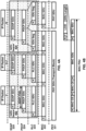
- FIG. 14A illustrates an example of CORESET configurations for a bandwidth part.
- the base station may transmit a DCI via a PDCCH on one or more control resource sets (CORESETs).
- a CORESET may comprise a time-frequency resource in which the UE tries to decode a DCI using one or more search spaces.
- the base station may configure a CORESET in the time-frequency domain.
- a first CORESET 1401 and a second CORESET 1402 occur at the first symbol in a slot.
- the first CORESET 1401 overlaps with the second CORESET 1402 in the frequency domain.
- a third CORESET 1403 occurs at a third symbol in the slot.
- a fourth CORESET 1404 occurs at the seventh symbol in the slot.
- CORESETs may have a different number of resource blocks in frequency domain.
- FIG. 14B illustrates an example of a CCE-to-REG mapping for DCI transmission on a CORESET and PDCCH processing.
- the CCE-to-REG mapping may be an interleaved mapping (e.g., for the purpose of providing frequency diversity) or a non-interleaved mapping (e.g., for the purposes of facilitating interference coordination and/or frequency-selective transmission of control channels).
- the base station may perform different or same CCE-to-REG mapping on different CORESETs.
- a CORESET may be associated with a CCE-to-REG mapping by RRC configuration.
- a CORESET may be configured with an antenna port quasi co-location (QCL) parameter.
- the antenna port QCL parameter may indicate QCL information of a demodulation reference signal (DMRS) for PDCCH reception in the CORESET.
- DMRS demodulation reference signal
- the base station may transmit, to the UE, RRC messages comprising configuration parameters of one or more CORESETs and one or more search space sets.
- the configuration parameters may indicate an association between a search space set and a CORESET.
- a search space set may comprise a set of PDCCH candidates formed by CCEs at a given aggregation level.
- the configuration parameters may indicate: a number of PDCCH candidates to be monitored per aggregation level; a PDCCH monitoring periodicity and a PDCCH monitoring pattern; one or more DCI formats to be monitored by the UE; and/or whether a search space set is a common search space set or a UE-specific search space set.
- a set of CCEs in the common search space set may be predefined and known to the UE.
- a set of CCEs in the UE-specific search space set may be configured based on the UE's identity (e.g., C-RNTI).
- the UE may determine a time-frequency resource for a CORESET based on RRC messages.
- the UE may determine a CCE-to-REG mapping (e.g., interleaved or non-interleaved, and/or mapping parameters) for the CORESET based on configuration parameters of the CORESET.
- the UE may determine a number (e.g., at most 10) of search space sets configured on the CORESET based on the RRC messages.
- the UE may monitor a set of PDCCH candidates according to configuration parameters of a search space set.
- the UE may monitor a set of PDCCH candidates in one or more CORESETs for detecting one or more DCIs.
- Monitoring may comprise decoding one or more PDCCH candidates of the set of the PDCCH candidates according to the monitored DCI formats.
- Monitoring may comprise decoding a DCI content of one or more PDCCH candidates with possible (or configured) PDCCH locations, possible (or configured) PDCCH formats (e.g., number of CCEs, number of PDCCH candidates in common search spaces, and/or number of PDCCH candidates in the UE-specific search spaces) and possible (or configured) DCI formats.
- the decoding may be referred to as blind decoding.
- the UE may determine a DCI as valid for the UE, in response to CRC checking (e.g., scrambled bits for CRC parity bits of the DCI matching a RNTI value).
- the UE may process information contained in the DCI (e.g., a scheduling assignment, an uplink grant, power control, a slot format indication, a downlink preemption, and/or the like).
- the UE may transmit an SR indicating that uplink data is available for transmission to the base station.
- the UE may transmit a UCI (e.g., HARQ acknowledgements (HARQ-ACK), CSI report, SR, and the like) via a physical uplink control channel (PUCCH) or a physical uplink shared channel (PUSCH).
- HARQ-ACK HARQ acknowledgements
- CSI report CSI report
- SR SR
- the UE may transmit the uplink control signaling via a PUCCH using one of several PUCCH formats.
- PUCCH format 0 may have a length of one or two OFDM symbols and may include two or fewer bits.
- the UE may transmit UCI in a PUCCH resource using PUCCH format 0 if the transmission is over one or two symbols and the number of HARQ-ACK information bits with positive or negative SR (HARQ-ACK/SR bits) is one or two.
- PUCCH format 1 may occupy a number between four and fourteen OFDM symbols and may include two or fewer bits.
- the UE may use PUCCH format 1 if the transmission is four or more symbols and the number of HARQ-ACK/SR bits is one or two.
- PUCCH format 2 may occupy one or two OFDM symbols and may include more than two bits.
- the UE may use PUCCH format 2 if the transmission is over one or two symbols and the number of UCI bits is two or more.
- PUCCH format 3 may occupy a number between four and fourteen OFDM symbols and may include more than two bits.
- the UE may use PUCCH format 3 if the transmission is four or more symbols, the number of UCI bits is two or more and PUCCH resource does not include an orthogonal cover code.
- PUCCH format 4 may occupy a number between four and fourteen OFDM symbols and may include more than two bits. The UE may use PUCCH format 4 if the transmission is four or more symbols, the number of UCI bits is two or more and the PUCCH resource includes an orthogonal cover code.
- the UE may select one of the plurality of PUCCH resource sets based on a total bit length of the UCI information bits (e.g., HARQ-ACK, SR, and/or CSI). If the total bit length of UCI information bits is two or fewer, the UE may select a first PUCCH resource set having a PUCCH resource set index equal to "0". If the total bit length of UCI information bits is greater than two and less than or equal to a first configured value, the UE may select a second PUCCH resource set having a PUCCH resource set index equal to "1".
- a total bit length of the UCI information bits e.g., HARQ-ACK, SR, and/or CSI.
- the UE may select a third PUCCH resource set having a PUCCH resource set index equal to "2". If the total bit length of UCI information bits is greater than the second configured value and less than or equal to a third value (e.g., 1406), the UE may select a fourth PUCCH resource set having a PUCCH resource set index equal to "3".
- a third value e.g. 1406
- the configuration parameters of the power saving operation may comprise: ps-RNTI indicating a PS-RNTI for DCI format 2_6 (e.g., based on example embodiment of FIG. 24 ), dci-Format2-6 indicating a number of search space sets for monitoring PDCCH for detection of DCI format 2_6 on an active DL BWP of the PCell or of the SpCell according to a common search space, size-DCI-2-6 indicating a payload size for DCI format 2_6.
- ps-RNTI indicating a PS-RNTI for DCI format 2_6 (e.g., based on example embodiment of FIG. 24 )
- dci-Format2-6 indicating a number of search space sets for monitoring PDCCH for detection of DCI format 2_6 on an active DL BWP of the PCell or of the SpCell according to a common search space
- size-DCI-2-6 indicating a payload size for DCI format 2_6.
- the DRX parameters that are common to the DRX groups are: drx-SlotOffset, drx-RetransmissionTimerDL, drx-RetransmissionTimerUL, drx-LongCycleStartOffset, drx-ShortCycle (optional), drx-ShortCycleTimer (optional), drx-HARQ-RTT-TimerDL, and drx-HARQ-RTT- TimerUL.
- a MAC entity of a wireless device may start or restart drx-ShortCycleTimer for this DRX group in the first symbol after the expiry of drx-InactivityTimer and/or use the Short DRX cycle for this DRX group, if the Short DRX cycle is configured. If drx-InactivityTimer for a DRX group expires, a MAC entity of a wireless device may use the Long DRX cycle for this DRX group, if the Short DRX cycle is not configured.
- a MAC entity of a wireless device may start drx-onDurationTimer after drx-SlotOffset from the beginning of the subframe, if DCP indication associated with the current DRX cycle received from lower layer indicated to start drx-onDurationTimer, or if all DCP occasion(s) in time domain, associated with the current DRX cycle occurred in Active Time considering grants/assignments/DRX Command MAC CE/Long DRX Command MAC CE received and Scheduling Request sent until 4 ms prior to start of the last DCP occasion, or during a measurement gap, or when the MAC entity monitors for a PDCCH transmission on the search
- a base station may configure a wireless device with uplink (UL) bandwidth parts (BWPs) and downlink (DL) BWPs to enable bandwidth adaptation (BA) on a PCell. If carrier aggregation is configured, the base station may further configure the wireless device with at least DL BWP(s) (i.e., there may be no UL BWPs in the UL) to enable BA on an SCell.
- BWPs bandwidth parts
- DL BWPs bandwidth adaptation
- the base station may further configure the wireless device with at least DL BWP(s) (i.e., there may be no UL BWPs in the UL) to enable BA on an SCell.
- an initial active BWP may be a first BWP used for initial access.
- a first active BWP may be a second BWP configured for the wireless device to operate on the SCell upon the SCell being activated.
- a base station and/or a wireless device may independently switch a DL BWP and an UL BWP.
- a base station and/or a wireless device may simultaneously switch a DL BWP and an UL BWP.
- a base station and/or a wireless device may switch a BWP between configured BWPs by means of a DCI or a BWP inactivity timer.
- the base station and/or the wireless device may switch an active BWP to a default BWP in response to an expiry of the BWP inactivity timer associated with the serving cell.
- the default BWP may be configured by the network.
- one UL BWP for each uplink carrier and one DL BWP may be active at a time in an active serving cell.
- FIG. 23 shows an example of BWP switching on a cell (e.g., PCell or SCell).
- a wireless device may receive, from a base station, at least one RRC message comprising parameters of a cell and one or more BWPs associated with the cell.
- the RRC message may comprise: RRC connection reconfiguration message (e.g., RRCReconfiguration ); RRC connection reestablishment message (e.g., RRCRestablishment ); and/or RRC connection setup message (e.g., RRCSetup ) .
- RRC connection reconfiguration message e.g., RRCReconfiguration
- RRC connection reestablishment message e.g., RRCRestablishment
- RRC connection setup message e.g., RRCSetup
- a wireless device may be provided by a higher layer parameter Default-DL-BWP a default DL BWP among the configured DL BWPs. If a wireless device is not provided a default DL BWP by the higher layer parameter Default-DL-BWP, the default DL BWP is the initial active DL BWP. In an example, a wireless device may be provided by higher layer parameter bwp-InactivityTimer, a timer value for the primary cell.
- the wireless device procedures on the secondary cell may be same as on the primary cell using the timer value for the secondary cell and the default DL BWP for the secondary cell.
- a wireless device may use the indicated DL BWP and the indicated UL BWP on the secondary cell as the respective first active DL BWP and first active UL BWP on the secondary cell or carrier.
- a set of PDCCH candidates for a wireless device to monitor is defined in terms of PDCCH search space sets.
- a search space set comprises a CSS set or a USS set.
- a wireless device monitors PDCCH candidates in one or more of the following search spaces sets: a Type0-PDCCH CSS set configured by pdcch-ConfigSIB1 in MIB or by searchSpaceSIB1 in PDCCH-ConfigCommon or by searchSpaceZero in PDCCH-ConfigCommon for a DCI format with CRC scrambled by a SI-RNTI on the primary cell of the MCG, a Type0A-PDCCH CSS set configured by searchSpaceOtherSystemInformation in PDCCH-ConfigCommon for a DCI format with CRC scrambled by a SI-RNTI on the primary cell of the MCG, a Type1-PDCCH CSS set configured by ra-SearchSpace in PDCCH-ConfigCommon for a DCI format with CRC scrambled
- o s is a slot offset indicated in the PDCCH configuration parameters.
- k s is a PDCCH monitoring periodicity indicated in the PDCCH configuration parameters.
- the wireless device monitors PDCCH candidates for the search space set for T s consecutive slots, starting from slot n s , f ⁇ , and does not monitor PDCCH candidates for search space set s for the next k s - T s consecutive slots.
- a USS at CCE aggregation level L ⁇ ⁇ 1, 2, 4, 8, 16 ⁇ is defined by a set of PDCCH candidates for CCE aggregation level L.
- a wireless device may monitor a set of PDCCH candidates according to configuration parameters of a search space set comprising a plurality of search spaces (SSs).
- the wireless device may monitor a set of PDCCH candidates in one or more CORESETs for detecting one or more DCIs.
- Monitoring may comprise decoding one or more PDCCH candidates of the set of the PDCCH candidates according to the monitored DCI formats.
- Monitoring may comprise decoding a DCI content of one or more PDCCH candidates with possible (or configured) PDCCH locations, possible (or configured) PDCCH formats (e.g., number of CCEs, number of PDCCH candidates in common SSs, and/or number of PDCCH candidates in the UE-specific SSs) and possible (or configured) DCI formats.
- the decoding may be referred to as blind decoding.
- the possible DCI formats may be based on example embodiments of FIG. 24 .
- FIG. 24 shows examples of DCI formats which may be used by a base station transmit control information to a wireless device or used by the wireless device for PDCCH monitoring.
- Different DCI formats may comprise different DCI fields and/or have different DCI payload sizes.
- Different DCI formats may have different signaling purposes.
- DCI format 0_0 may be used to schedule PUSCH in one cell.
- DCI format 0_1 may be used to schedule one or multiple PUSCH in one cell or indicate CG-DFI (configured grant-Downlink Feedback Information) for configured grant PUSCH, etc.
- the DCI format(s) which the wireless device may monitor in a SS may be configured based on example embodiments with respect to FIG. 28 , which will be explained later.
- a '0' value for a bit of the bitmap indicates an active DL BWP, provided by dormantBWP-Id (e.g., as shown in FIG. 25 ), for the wireless device for each activated SCell in the corresponding group of configured SCells.
- a '1' value for a bit of the bitmap may indicate an active DL BWP, provided by firstOutsideActiveTimeBWP-Id, for the wireless device for each activated SCell in the corresponding group of configured SCells, if a current active DL BWP is the dormant DL BWP, or may indicate a current active DL BWP, for the wireless device for each activated SCell in the corresponding group of configured SCells, if the current active DL BWP is not the dormant DL BWP.
- the wireless device may set the active DL BWP to the indicated active DL BWP.
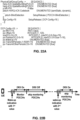
- a wireless device may be provided (e.g., based on FIG. 22A and/or FIG. 28 ) search space sets to monitor PDCCH for detection of DCI format 2_6 in the active DL BWP of a PCell or of a SpCell.
- the wireless device may detect DCI format 2_6.
- a DCI format 2_6 may comprise a SCell dormancy indication field, wherein the SCell dormancy indication field is a bitmap with size equal to a number of groups of configured SCells, provided by dormancyGroupWithinActiveTime (e.g., as shown in FIG. 25 ), wherein each bit of the bitmap corresponds to a group of configured SCells from the number of groups of configured SCells.
- the indicated active DL BWP may be an active DL BWP, provided by dormantBWP-Id, for the wireless device for each activated SCell in a group of configured SCells, if a bit, corresponding to the group, of the SCell dormancy indication bitmap is set to a '0' value.
- the indicated active DL BWP may be an active DL BWP, provided by firstWithinActiveTimeBWP-Id, for the wireless device for each activated SCell in the corresponding group of configured SCells, if a current active DL BWP is the dormant DL BWP, or a current active DL BWP, for the wireless device for each activated SCell in the corresponding group of configured SCells, if the current active DL BWP is not the dormant DL BWP.
- the wireless device may consider, for transport block 1, a sequence of fields of MCS, NDI, RV and HARQ process number, antenna port(s), DMRS sequence initialization as providing a bitmap to each configured SCell, in an ascending order of SCell index.
- a '0' value for a bit of the bitmap may indicate an active DL BWP, provided by dormantBWP-Id, for the wireless device for a corresponding activated SCell.
- a '1' value for a bit of the bitmap may indicate an active DL BWP, provided by firstWithinActiveTimeBWP-Id, for the wireless device for a corresponding activated SCell, if a current active DL BWP is the dormant DL BWP or a current active DL BWP, for the wireless device for a corresponding activated SCell, if the current active DL BWP is not the dormant DL BWP.
- the wireless device may set the active DL BWP to the indicated active DL BWP.
- an active DL BWP provided by dormantBWP-Id for a wireless device on an activated SCell is not a default DL BWP for the wireless device on the activated SCell, the BWP inactivity timer is not used for transitioning from the active DL BWP provided by dormantBWP-Id to the default DL BWP on the activated SCell.
- FIG. 26 shows an example embodiment of dormancy indication based on cell grouping.
- a base station may transmit to a wireless device one or more RRC messages comprising configuration parameters of a plurality of SCells, the plurality of SCells being grouped into a plurality of SCell groups (e.g., SCell group 1, SCell group 2 in FIG. 26 ) for dormancy indication.
- Each SCell group of the plurality of SCell groups may comprise one or more SCells of the plurality of SCells.
- SCell group 1 comprises Cell 1, Cell 2 and the like.
- SCell group 2 comprises Cell 3, Cell 4 and the like.
- a SCell of the plurality of SCells may comprise a plurality of BWPs comprising at least one of: a first BWP as a non-dormant BWP, and/or a second BWP as a dormant BWP.
- a wireless device may apply a dormancy indication for all (active) SCells of the SCell group, comprising transitioning, for each of the SCells of the SCell group, to a corresponding dormant BWP of each of the SCells of the SCell group, in response to receiving the dormancy indication indicating a dormant state for the SCell group.
- a wireless device may apply a non-dormancy indication for all SCells of the SCell group, comprising transitioning, for each of the SCells of the SCell group, to a corresponding non-dormant BWP of each of the SCells of the SCell group, in response to receiving the dormancy indication indicating a non-dormant state for the SCell group.
- the wireless device may receive a dormancy indication bitmap comprising a plurality of dormancy indication bits, wherein each bit of the plurality of dormancy indication bits, corresponding to a respective SCell group of the plurality of SCell groups, indicates a dormant/non-dormant state for the respective SCell group.
- the dormancy indication bitmap may be comprised in a DCI.
- a first bit e.g., 1 st bit in FIG. 26
- a second bit e.g., 2 nd bit in FIG. 26
- the dormancy indication bitmap, being set to "1” may indicate a non-dormant state of SCell group 2, and so on.
- the wireless device in response to the first bit of the dormancy indication bitmap indicating the dormant state for SCell group 1, the wireless device may transition one or more SCells of SCell group 1 into dormant state, comprising switching from an active BWP of Cell 1 to a dormant BWP of Cell 1, switching from an active BWP of Cell 2 to a dormant BWP of Cell 2, and the like.
- the wireless device in response to the first bit of the dormancy indication bitmap indicating the dormant state for SCell group 1, the wireless device may maintain a dormant state of a SCell of SCell group 1 if the SCell is in the dormant state before receiving the dormancy indication.
- the wireless device may perform actions on a respective dormant BWP on Cell 1, Cell 2 and the like based on one or more embodiments of FIG. 26 .
- the wireless device may transition one or more SCells of SCell group 2 into a non-dormant state, comprising switching to a non-dormant BWP of Cell 3 as an active BWP of Cell 3, switching to a non-dormant BWP of Cell 4 as an active BWP of Cell 4, and the like.
- the wireless device may maintain a non-dormant state of a SCell of SCell group 2 if the SCell is in the non-dormant state before receiving the dormancy indication bitmap.
- the wireless device may perform actions on a respective non-dormant BWP on Cell 3, Cell 4 and the like based on one or more embodiments of FIG. 23 . Transitioning SCell state between dormancy and non-dormancy based on cell grouping may improve signaling overhead, transmission latency, and/or reduce power consumption of a wireless device.
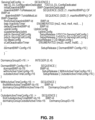
- FIG. 27 shows an example of RRC configuration parameters (e.g., BWP-DownlinkDedicated IE) of a downlink BWP of a serving cell.
- a base station may transmit to a wireless device (or a plurality of wireless devices) one or more configuration parameters of a downlink BWP (e.g., initial downlink BWP) of a serving cell.
- the one or more configuration parameters of the downlink BWP may comprise: one or more parameters for PDCCH of the downlink BWP (e.g., in pdcch-Config IE), and one or more other parameters.
- a pdcch-Config IE may comprise parameters of one or more control resource sets (CORESETs) which can be used in any common or UE-specific search spaces for the bandwidth part.
- the one or more parameters of the PDCCH may indicate a plurality of search spaces for the bandwidth part, each search space being associated with a search space ID.
- the one or more parameters of the PDCCH may comprise a search space switch configuration parameter (e.g., searchSpaceSwitchConfig-r16 IE) indicating one or more cell groups for search space switching.
- a wireless device When a bit, of a search space switching indication bitmap of a DCI (e.g., DCI format 2_0), indicates a first value, a wireless device may switch to a first search space group for all cells in a cell group corresponding to the bit.
- a bit, of a search space switching indication bitmap of a DCI indicates a second value, a wireless device may switch to a second search space group for all cells in a cell group corresponding to the bit.
- a CORESET may be associated with a CORESET index (e.g., ControlResourceSetId ) .
- the CORESET index with a value of 0 may identify a common CORESET configured in MIB and in ServingCellConfigCommon (controlResourceSetZero ) and may not be used in the ControlResourceSet IE.
- the CORESET index with other values may identify CORESETs configured by dedicated signaling or in SIB1.
- the controlResourceSetId is unique among the BWPs of a serving cell.
- a CORESET may be associated with coresetPoolIndex indicating an index of a CORESET pool for the CORESET.
- a CORESET may be associated with a time duration parameter (e.g., duration) indicating contiguous time duration of the CORESET in number of symbols.
- configuration parameters of a CORESET may comprise at least one of: frequency resource indication (e.g., frequencyDomainResources ) , a CCE-REG mapping type indicator (e.g., cce-REG-MappingType ) , a plurality of TCI states, an indicator indicating whether a TCI is present in a DCI, and the like.
- the frequency resource indication comprising a number of bits (e.g., 45 bits), indicates frequency domain resources, each bit of the indication corresponding to a group of 6 RBs, with grouping starting from the first RB group in a BWP of a cell (e.g., SpCell, SCell).
- the first (left-most / most significant) bit corresponds to the first RB group in the BWP, and so on.
- a bit that is set to 1 indicates that an RB group, corresponding to the bit, belongs to the frequency domain resource of this CORESET. Bits corresponding to a group of RBs not fully contained in the BWP within which the CORESET is configured are set to zero.
- a base station may transmit to a wireless device one or more RRC messages comprising PDCCH configuration parameters (e.g., PDCCH-ServingCellConfig IE as shown in FIG. 27 ) applicable for all downlink BWPs of a cell.
- the PDCCH configuration parameters may comprise a timer value (e.g., an integer in units of symbol/slot, or in units of ms) for a search space switch timer (e.g., searchSpaceSwitchTimer IE).
- search space switch timer and the time value may be used for a search space switching operation which will be described in FIG. 30A .
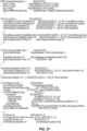
- FIG. 28 shows an example of configuration of a search space (e.g., SearchSpace IE) of a BWP.
- one or more search space configuration parameters of a search space may comprise at least one of: a search space ID ( searchSpaceId ) , a control resource set ID ( controlResourceSetId ) , a monitoring slot periodicity and offset parameter ( monitoringSlotPeriodicityAndOffset ), a search space time duration value ( duration ) , a monitoring symbol indication ( monitoringSymbolsWithinSlot ) , a number of candidates for an aggregation level ( nrofCandidates ), and/or a SS type indicating a common SS type or a UE-specific SS type ( searchSpaceType ).
- the monitoring slot periodicity and offset parameter may indicate slots (e.g., in a radio frame) and slot offset (e.g., related to a starting of a radio frame) for PDCCH monitoring.
- the monitoring symbol indication may indicate on which symbol(s) of a slot a wireless device may monitor PDCCH on the SS.
- the control resource set ID may identify a control resource set on which a SS may be located.
- the one or more search space configuration parameters of a search space may comprise a search space group list (e.g., searchSpaceGroupIdList ) , indicating one or more search space groups the search space may belong to, for search space switching operation.
- a search space switching operation may be based on example embodiment of FIG. 29 , FIG. 30A and/or FIG. 30B .
- FIG. 29 shows an example of DCI format 2_0 comprising one or more search space set group (or SSSG) switching indications (or Search space set group switching flags ) .
- a search space set group may be equivalent to a search space group (SSG).
- a DCI format 2_0 may comprise one or more slot format indicator (e.g., slot format indicator 1, slot format indicator 2, ... slot format indicator N), one or more available RB set indicators, one or more COT duration indications, one or more SSS group switching flags.
- each of the one or more SSS group switching flags may correspond to a respective cell group of a plurality of cell groups.
- the plurality of cell groups may be implemented based on example embodiments described above with respect to FIG. 27 .
- Each cell group of the plurality of cell groups may comprise one or more cells.
- a SSS group switching flag, of the one or more SSS group switching flags, corresponding to a cell group may indicate, when setting to a first value, switching from a first SSS group to a second SSS group for each cell of the cell group.
- the SSS group switching flag may indicate, when setting to a second value, switching from the second SSS group to the first SSS group for each cell of the cell group.
- a plurality of SSS groups, comprising the first SSS group and the second SSS group may be configured based on example embodiments described above with respect to FIG. 28 .
- the wireless device may perform SSS group switching based on example embodiment of FIG. 30A and FIG. 30B .
- FIG. 30A shows an example of SSS group switching based on a DCI (e.g., DCI format 2_0, or other DCI formats described in FIG. 24 ).
- a wireless device may be provided a group index for a search space set (e.g., a Type3-PDCCH CSS set, a USS set, or any other type of search space set) by searchSpaceGroupIdList (e.g., based on example embodiment of FIG. 28 ) for PDCCH monitoring on a serving cell.
- the wireless device may be provided a plurality of SSS groups (e.g., or SSGs).
- the wireless device may monitor PDCCH based on configuration parameters of the PDCCH, e.g., based on example embodiments described above with respect to FIG. 28 .
- the wireless device may not be provided searchSpaceGroupIdList for a search space set.
- the embodiments of FIG. 30A may not be applicable for PDCCH monitoring on the search space set if the search space set is not configured with searchSpaceGroupIdList.
- the wireless device may monitor the search space set on a BWP, e.g., without switching away from the search space set for PDCCH monitoring.
- a wireless device is provided cellGroupsForSwitchList (e.g., based on example embodiments shown in FIG. 27 ), indicating one or more groups of serving cells
- the embodiments of FIG. 30A may apply to all (active) serving cells within each group. If the wireless device is not provided cellGroupsForSwitchList, the embodiments of FIG. 30A may apply only to a serving cell for which the wireless device is provided searchSpaceGroupIdList.
- the wireless device may reset PDCCH monitoring according to search space sets with group index 0, if provided by searchSpaceGroupIdList.
- a wireless device may be provided by searchSpaceSwitchDelay (e.g., as shown in FIG. 27 ) with a number of symbols P switch .
- a minimum value of P switch may be determined based on UE processing capability and numerology.
- FIG. 30B shows an example embodiment of minimum value of P switch .
- the value indicated in searchSpaceSwitchDelay may be equal to or greater than a minimum value corresponding to the numerology of the BWP and a UE processing capability of the wireless device.
- a wireless device may be provided, by searchSpaceSwitchTimer (in units of slots, e.g., as shown in FIG. 27 ), with a timer value for a serving cell that the wireless device is provided searchSpaceGroupIdList or, if provided, for a set of serving cells provided by cellGroupsForSwitchList.
- the wireless device may decrement the timer value by one after each slot based on a reference SCS configuration that is a smallest SCS configuration ⁇ among all configured DL BWPs in the serving cell, or in the set of serving cells.
- the wireless device may maintain the reference SCS configuration during the timer decrement procedure.
- searchSpaceSwitchTimer may be defined as a value in unit of slots for monitoring PDCCH in the active DL BWP of the serving cell before moving to a default search space group (e.g., search space group 0).
- a valid timer value may be one of ⁇ 1, ..., 20 ⁇ .
- a valid timer value may be one of ⁇ 1, ..., 40 ⁇ .
- a valid timer value may be one of ⁇ 1, ..., 80 ⁇ .
- the base station may configure a same timer value for all serving cells in the same CellGroupForSwitch.
- the wireless device may monitor PDCCH on a first SSS group (e.g., 1 st SSS group or a SSS with group index 0, or 1 st SSG) based on configuration of SSS groups of a BWP of a cell.
- the wireless device may be provided by SearchSpaceSwitchTrigger with a location of a search space set group switching flag field for a serving cell in a DCI format 2_0.
- the SearchSpaceSwitchTrigger may be configured based on example embodiments of FIG. 28 .
- the wireless device may receive a DCI (e.g., 1 st DCI in FIG. 30A with DCI format 2_0) at a first slot (e.g., T1).
- the DCI may indicate a SSS group switching for the cell, e.g., when a value of the SSS group switching flag field in the DCI format 2_0 is 1.
- the wireless device may start monitoring PDCCH according to a second SSS group (e.g., 2 nd SSS group or a SSS with group index 1, or 2 nd SSG) and stops monitoring PDCCH on the first SSS group (or the SSS with group index 0 for the serving cell.
- a second SSS group e.g., 2 nd SSS group or a SSS with group index 1, or 2 nd SSG
- the wireless device may start monitoring PDCCH on the second SSS group (e.g., 2 nd SSS group or a SSS with group index 1, or 2 nd SSG) and stop monitoring PDCCH on the first SSS group at a second slot (e.g., T2).
- the wireless device may determine a gap for SSS group switching based on P switch .
- the second slot is at least P switch symbols after a last symbol of (e.g., the first slot) the PDCCH with the DCI format 2_0.
- the wireless device may set (or reset), at the second slot (e.g., T2), a timer value of the search space switching timer to the value provided by searchSpaceSwitchTimer.
- the wireless device may monitor PDCCH on a second SSS group (e.g., 2 nd SSS group or a SSS with group index 1, or 2 nd SSG) based on configuration of SSS groups of a BWP of a cell.
- the wireless device may be provided by SearchSpaceSwitchTrigger a location of a search space set group switching flag field for a serving cell in a DCI format 2_0.
- the wireless device may receive a DCI.
- the DCI may indicate a SSS group switching for the cell, e.g., when a value of the search space set group switching flag field in the DCI format 2_0 is 0, the wireless device may start monitoring PDCCH according to search space sets with group index 0 and stop monitoring PDCCH according to search space sets with group index 1 for the serving cell.
- the wireless device may start monitoring the PDCCH according to search space set with group index 0 and stop monitoring PDCCH according to search space sets with group 1 at a first slot that is at least P switch symbols after the last symbol of the PDCCH with the DCI format 2_0.
- the wireless device may receive DCI(s) indicating downlink assignment, or uplink grant, or common control information.
- the wireless device may process the DCI(s) accordingly (e.g., receiving PDSCH, transmitting PUSCH, or receiving the common control information, etc.).
- the timer may expire at a third slot (e.g., T3).
- the wireless device may start monitoring PDCCH for the serving cell according to the 1 st SSG (e.g., search space sets with group index 0), and stop monitoring PDCCH according to the 2 nd SSG, for the serving cell at the beginning of a fourth slot (e.g., T4).
- the fourth slot may be at least P switch symbols after the third slot where the searchSpaceSwitchTimer expires.
- a wireless device may not be provided SearchSpaceSwitchTrigger for a serving cell, e.g., SearchSpaceSwitchTrigger being absent in configuration parameters of SlotFormatIndicator, wherein the SlotFormatIndicator is configured for monitoring a Group-Common-PDCCH for Slot-Format-Indicators (SFI).
- the DCI format 2_0 may not comprise a SSS group switching flag field.
- the wireless device may start monitoring PDCCH according to a second SSS group (e.g., a search space sets with group index 1) and stop monitoring PDCCH according to the first SSS group, for the serving cell.
- the wireless device may start monitoring PDCCH according to the second SSS group and stop monitoring PDCCH according to the first SSS group at a first slot that is at least P switch symbols after the last symbol of the PDCCH with the DCI format.
- the wireless device may set (or restart) the timer value to the value provided by searchSpaceSwitchTimer if the wireless device detects a DCI format by monitoring PDCCH in any search space set.
- a wireless device may not be provided SearchSpaceSwitchTrigger for a serving cell.
- SearchSpaceSwitchTrigger if the wireless device monitors PDCCH for a serving cell according to a first SSS group (e.g., a search space sets with group index 1), the wireless device may start monitoring PDCCH for the serving cell according to a second SSS group (e.g., a search space sets with group index 0), and stop monitoring PDCCH according to the first SSS group, for the serving cell at the beginning of the first slot that is at least P switch symbols after a slot where the timer expires or, if the wireless device is provided a search space set to monitor PDCCH for detecting a DCI format 2_0, after a last symbol of a remaining channel occupancy duration for the serving cell that is indicated by DCI format 2_0.
- a first SSS group e.g., a search space sets with group index 1
- the wireless device may start monitoring PDCCH for the serving cell according to a second SSS group
- a wireless device may determine a slot and a symbol in a slot to start or stop PDCCH monitoring according to search space sets for a serving cell that the wireless device is provided searchSpaceGroupIdList or, if cellGroupsForSwitchList is provided, for a set of serving cells, based on the smallest SCS configuration ⁇ among all configured DL BWPs in the serving cell or in the set of serving cells and, if any, in the serving cell where the wireless device receives a PDCCH and detects a corresponding DCI format 2_0 triggering the start or stop of PDCCH monitoring according to search space sets.
- a wireless device may perform PDCCH skipping based power saving operation.
- FIG. 31 shows an example of PDCCH skipping based power saving operation.
- a base station may transmit to a wireless device one or more RRC messages comprising configuration parameters of PDCCH for a BWP of a cell (e.g., based on example embodiments described above with respect to FIG. 27 and/or FIG. 28 ).
- the wireless device may monitor PDCCH on the BWP.
- the BWP may a downlink BWP which is in active state.
- the wireless device may activate the BWP based on example embodiments described above with respect to FIG. 23 .
- the wireless device may receive, at a first slot (T1), a first DCI (e.g., 1 st DCI) indicating skipping (or stopping) monitoring PDCCH within a time window.
- a first DCI e.g., 1 st DCI
- a time value for the time window may be indicated by the first DCI and/or configured by the one or more RRC messages.
- the wireless device may stop monitoring PDCCH on the BWP. Stopping monitoring PDCCH on the BWP may comprise stopping monitoring PDCCH on one or more SSS groups configured on the BWP.
- the wireless device may maintain an active state of the BWP.
- the first DCI may not indicate an active BWP switching.
- the base station may not transmit PDCCH to the wireless device.
- the wireless device may resume PDCCH monitoring on the BWP. Based on resuming PDCCH monitoring, the wireless device may receive a second DCI (e.g., 2 nd DCI(s)) scheduling TB via PDSCH. The wireless device may receive the TB via the PDSCH scheduled by the second DCI. In an example, in response to the time window expiring, the base station may transmit the second DCI to the wireless device.
- a second DCI e.g., 2 nd DCI(s) scheduling TB via PDSCH.
- the base station may transmit the second DCI to the wireless device.
- a wireless device may perform a plurality of power saving operations.
- the plurality of power saving operations may comprise PDCCH skipping based power saving operation (e.g., based on example embodiments described above with respect to FIG. 31 ), BWP switching based power saving operation (e.g., based on example embodiments described above with respect to FIG. 23 and/or FIG. 26 ) and SSG switching based power saving operation (e.g., based on example embodiments described above with respect to FIG. 30A and/or FIG. 30B ).
- PDCCH skipping based power saving operation e.g., based on example embodiments described above with respect to FIG. 31
- BWP switching based power saving operation e.g., based on example embodiments described above with respect to FIG. 23 and/or FIG. 26
- SSG switching based power saving operation e.g., based on example embodiments described above with respect to FIG. 30A and/or FIG. 30B .
- Different power saving operations may provide different power saving
- PDCCH skipping based power saving operation may not comprise an active BWP switching.
- a wireless device may skip PDCCH monitoring for a time duration while maintaining an active state of a BWP on a cell. Therefore, no RF chain and/or beam direction retuning is required.
- power saving operation based on PDCCH skipping (e.g., FIG. 31 ) on an active BWP may provide better power saving gain than power saving operation based on active BWP switching (e.g., FIG. 23 ) or dormant BWP switching (e.g., FIG. 26 ).
- the BWP switching based power saving may comprise an active BWP switching, which may take several milliseconds and/or require the wireless service to retune the RF chain and/or beam direction.
- the wireless device may take several symbols, or a slot (or a few slots) to stop monitoring PDCCH, which may bring higher power saving gain than BWP switching based power saving operation.
- a wireless device may take a number of slots for switching an active BWP on a cell depending on a numerology and a type of wireless device capability.
- a numerology index of a BWP e.g., a source BWP or a target BWP
- the wireless device may take 1 slot to switch an active BWP on a cell if wireless device indicates the wireless device capability type 1 or may take 3 slots if the wireless device indicates the wireless device capability type 2.
- the wireless device may take 2 slots to switch an active BWP on a cell if wireless device indicates the wireless device capability type 1 or may take 5 slots if the wireless device indicates the wireless device capability type 2.
- the wireless device may take 3 slots to switch an active BWP on a cell if wireless device indicates the wireless device capability type 1 or may take 9 slots if the wireless device indicates the wireless device capability type 2.
- the wireless device may take 6 slots to switch an active BWP on a cell if wireless device indicates the wireless device capability type 1 or may take 18 slots if the wireless device indicates the wireless device capability type 2.
- a wireless device may perform SSG switching based power saving operation.
- the wireless device may be configured with a SSG switching delay (P switch ).
- the wireless device may apply the SSG switching delay for a SSG switching indication.
- the application delay for SSG switching indication is used for accommodating blind decoding the DCI, switching blind decoding from the first SSG to the second SSG, channel estimation, etc.
- the SSG switching delay may be in a range of 10 ⁇ 52 symbols depending on configuration of the base station (e.g., based on example embodiment described above with respect to FIG. 30A and/or FIG. 30B ).
- PDCCH skipping based power saving operation may require less application delay for applying a PDCCH skipping indication.
- the application delay for PDCCH skipping indication may be used for accommodating blind decoding PDCCH.
- the application delay may be a number of symbols, or a few slots (e.g., 1 slot in some case). Therefore, in some case, PDCCH skipping based power saving operation may provide higher power saving gain than SSG switching based power saving operation.
- a wireless device when configured with multiple cells (or carrier aggregation, CA), may perform different power saving operations on different cells.
- the wireless device may perform BWP switching (or active/dormant BWP switching) based power saving operation on first cells when the wireless device has no data transmission on the first cells.
- the wireless device may perform SSG switching based power saving operation on second cells when the wireless device has few data transmissions on the second cells.
- the wireless device may perform PDCCH skipping based power saving operation on third cells when the wireless device has no data transmissions on the third cells and the wireless device may have data transmission soon on the third cells.
- Different power saving operations may provide different power saving gains in different cases, e.g., for different data transmission needs/requirements.
- a base station may transmit a SCell dormancy indication and/or a SSG switching indication to a wireless device for different cell (or cell groups) via different DCIs.
- the base station may transmit a first DCI (e.g., DCI format 2_0) indicating SSG switching based power saving for first cell groups.
- the base station may transmit a second DCI (e.g., DCI format 2_6, or DCI format 1_1/0_1) indicating dormant BWP switching based power saving for second cell groups.
- the base station may transmit a third DCI (e.g., DCI format 1_1/0_1) indicating PDCCH skipping based power saving operation for third cell groups.
- a base station may transmit, to a wireless device, RRC messages comprising configuration parameters of a plurality of cell groups and a plurality of PS operations.
- the base station may transmit a DCI comprising a plurality of cell-group specific PS indications, each PS indication indicating one of the plurality of power saving operations configured by the base station.
- the wireless device may perform cell-group specific power saving operations for a plurality of cell groups.
- Each of cell-group specific power saving operations may be performed with separate and/or independent application delay.
- Example embodiments may reduce signaling overhead for PS indications for a plurality of cells because multiple DCIs may not be needed to configure power saving operations for multiple cell groups.
- Example embodiments may also reduce power consumption of a wireless device for receiving PS indications for the plurality of cells.
- FIG. 32 shows an example of configuration of a plurality of power saving operations.
- a base station may transmit to a wireless device, one or more RRC messages comprising configuration parameters of a plurality (or a list) of power saving operations on a plurality of cells.
- the plurality of power saving operations may comprise: one or more first power saving operations associated with dormant BWP switching, one or more second power saving operations associated with SSG switching, one or more third power saving operations associated with PDCCH skipping, etc.
- a first power saving operation (e.g., 1 st entry of the list), of the plurality of power saving operations, may indicate switching from a non-dormant BWP to a dormant BWP on a cell.
- a second power saving operation (e.g., 2 nd entry of the list), of the plurality of power saving operations, may indicate switching from a dormant BWP to a non-dormant BWP on a cell.
- a third power saving operation (e.g., 3 rd entry of the list), of the plurality of power saving operations, may indicate switching from a first (non-dormant) SSG to a second (non-dormant) SSG on an active BWP of a cell.
- a fourth power saving operation (e.g., 4 th entry of the list), of the plurality of power saving operations, may indicate switching from a dormant SSG to a non-dormant SSG on an active BWP of a cell.
- a fifth power saving operation (e.g., 5 th entry of the list), of the plurality of power saving operations, may indicate switching from a non-dormant SSG to a dormant SSG on an active BWP of a cell.
- a sixth power saving operation (e.g., 6 th entry of the list), of the plurality of power saving operations, may indicate stopping (or skipping) monitoring PDCCH for a first number of slots on an active BWP of a cell.
- a seventh power saving operation (e.g., 7 th entry of the list), of the plurality of power saving operations, may indicate stopping (or skipping) monitoring PDCCH for a second number of slots on an active BWP of a cell.
- An eighth power saving operation (e.g., 8 th entry of the list), of the plurality of power saving operations, may indicate stopping (or skipping) monitoring PDCCH for a third number of slots on an active BWP of a cell, etc.
- the base station may flexibly determine a plurality of power saving operations for a wireless device.
- the base station may not configure the 6 th 7 th and/or 8 th entry etc. in FIG. 32 .
- the base station may not configure the 3 rd , 4 th and/or 5 th entry etc. in FIG. 32 .
- the base station may not configure the 1 st and 2 nd entry etc. in FIG. 32 .
- Configuration of a wireless device specific power saving operation list may allow the base station to transmit a DCI indicating a power saving operation from the power saving operation list for a wireless device.
- Example embodiments may reduce signaling overhead for power saving operation indication.
- FIG. 33 shows an example of cell grouping for a plurality of power saving operations.
- a base station may transmit to a wireless device, one or more RRC messages comprising configuration parameters of a plurality (or a list) of power saving operations on a plurality of cells.
- the list or the plurality of power saving operations may be implemented based on example embodiments of FIG. 32 .
- the plurality of cells may be grouped into a number of cell groups for power saving operation indication. As shown in FIG. 33 , the plurality of cells may comprise cell 1, cell 2, cell 3, cell 4, cell 5, cell 6 and etc.
- the base station may group the plurality of cells into a number of cell groups comprising: a first cell group (1 st cell group) comprising cell 1 and cell 2 etc., a second cell group (2 nd cell group) comprising cell 3 and cell 4 etc., a third cell group (3 rd cell group) comprising cell 4 and cell 5 etc.
- a cell of the plurality of cells may uniquely belong to one of the number of cell groups.
- a cell group may comprise one or more cells.
- the one or more RRC messages may comprise a location parameter indicating that a PS indication, of a plurality of PS indications in a DCI, corresponds to a respective cell group of the number of cell groups.
- Each one of the plurality of PS indications may correspond to a respective cell group of the number of cell groups.
- a PS indication, of the plurality of PS indications in the DCI may indicate one of the list (or plurality) of power saving operations (e.g., based one example embodiments described above with respect to FIG. 32 ).
- the DCI may be transmitted via a PDCCH resource.
- the DCI may be based on example embodiments described above with respect to FIG. 24 .
- FIG. 34 shows an example embodiment of cell grouping and cell group based PS indication by a DCI, based on example embodiments described above with respect to FIG. 32 and/or FIG. 33 .
- a base station may transmit to a wireless device a DCI comprising a plurality of PS indications for a number of cell groups.
- a first PS indication (1 st PS indication) of the plurality of PS indications may correspond to 1 st cell group of the number of cell groups based on a first location parameter, associated with the 1 st cell group, indicating the first PS indication is associated with the 1 st cell group.
- a second PS indication (2 nd PS indication) of the plurality of PS indications may correspond to 2 nd cell group of the number of cell groups based on a second location parameter, associated with the 2 nd cell group, indicating the second PS indication is associated with the 2 nd cell group.
- a third PS indication (3 rd PS indication) of the plurality of PS indications may correspond to 3 rd cell group of the number of cell groups based on a third location parameter, associated with the 3 rd cell group, indicating the third PS indication is associated with the 3 rd cell group, etc.
- the wireless device may receive the DCI comprising the plurality of PS indications.
- the wireless device may determine, based on the 1 st location parameter, a first PS indication for a first cell group.
- the wireless device may switch to a respective dormant BWP for each (activated) cell (e.g., cell 1, cell 2 based on example embodiments described above with respect to FIG. 33 ) of the first cell group.
- the wireless device may switch to dormant BWP based on example embodiments described above with respect to FIG. 26 .
- the wireless device may determine, based on the 2 nd location parameter, a second PS indication for a second cell group.
- the wireless device may switch to a respective second SSG on an active BWP of each (activated) cell (cell 3 and/or cell 4 based on FIG. 33 ) of the second cell group.
- the wireless device may switch from a first SSG to a second SSG based on example embodiments described above with respect to FIG. 30A and/or FIG. 30B .
- the wireless device may determine, based on the Nth location parameter, a Nth PS indication for a Nth cell group.
- the wireless device may skip (or stop) PDCCH monitoring on an active BWP of each (activated) cell of the Nth cell group.
- the wireless device may skip (or stop) PDCCH monitoring for the first number of slots based on example embodiments described above with respect to FIG. 31 .
- a PS indication of the DCI may comprise a number of bits indicating one of the plurality of PS operations configured by the base station. In an example, when there are 8 entries in the list as shown in FIG. 32 , the PS indication may be a 3-bit DCI field. In an example, when there are 4 entries in the list as shown in FIG. 32 , the PS indication may be a 2-bit DCI field, etc.
- FIG. 35 show an example embodiment of power saving operation on a plurality of cells, based on example embodiments described above with respect to FIG. 32 , FIG. 33 and/or FIG. 34 .
- a wireless device may receive, from a base station, one or more RRC messages comprising configuration parameters of a plurality of PS operations on a plurality of cells.
- the plurality of PS operations may be implemented based on example embodiments described above with respect to FIG. 32 .
- the plurality of cells may be grouped into a number of cell groups based on example embodiments described above with respect to FIG. 33 .
- the configuration parameters may comprise, for each cell group of the number of cell groups, a respective location parameter indicating a power saving indication (PSI), of a plurality of PSIs in a DCI, correspond to the cell group.
- PSI power saving indication
- the wireless device may receive, at a first slot T1, a DCI comprising a plurality of PSIs.
- Each PSI of the plurality of PSIs may indicate one of the plurality of PS operations configured in the one or more RRC messages.
- the wireless device may determine, for a first cell group (1 st cell group), a first PSI (1 st PSI) from the plurality of PSIs, based on a first location parameter associated with the first cell group.
- the first PSI may indicate PDCCH skipping (for a first number of slots), e.g., when the first PSI indicates the 6 th entry of the list of PS operations in FIG. 32 .
- the wireless device may stop, at a second slot T2, monitoring PDCCH on an active BWP of each (active) cell of the first cell group (for the first number of slots).
- the application delay (e.g., a gap between T2 and T1) may be configured in the one or more RRC messages and/or indicated by the DCI.
- the application delay may be predefined as a fixed value.
- the wireless device may determine, for a second cell group (2 nd cell group), a second PSI (2 nd PSI) from the plurality of PSIs, based on a second location parameter associated with the second cell group.
- the second PSI may indicate switching form a first SSG to a second SSG, e.g., when the second PSI indicates the 3 rd entry of the list of PS operations in FIG. 32 .
- the wireless device may, at a third slot T3, stop monitoring PDCCH via the first SSG and start monitoring the PDCCH via the second SSG on an active BWP of each (active) cell of the second cell group.
- the application delay (e.g., a gap between T3 and T1) may be configured in the one or more RRC messages and/or indicated by the DCI.
- the application delay may be predefined as a fixed value.
- the wireless device may determine, for a third cell group (3 rd cell group), a third PSI (3 rd PSI) from the plurality of PSIs, based on a third location parameter associated with the third cell group.
- the third PSI may indicate a dormancy transition, e.g., when the third PSI indicates the 1 st entry of the list of PS operations in FIG. 32 .
- the wireless device may, at a fourth slot T4, switch from an active BWP to a dormant BWP of each (active) cell of the third cell group.
- the application delay (e.g., a gap between T4 and T1) may be configured in the one or more RRC messages and/or indicated by the DCI.
- the application delay may be predefined as a fixed value.
- a base station may transmit to a wireless device a DCI comprising a plurality of cell-group specific PS indications, each PS indication indicating one of a plurality of power saving operations configured by the base station.
- the wireless device may perform cell-group specific power saving operations for a plurality of cell groups. Each of cell-group specific power saving operations may be performed with separate and/or independent application delay.
- Example embodiments may reduce signaling overhead for PS indications for a plurality of cells.
- Example embodiments may reduce power consumption of a wireless device for receiving PS indications for the plurality of cells.
- a wireless device may not be capable of performing different PS operations simultaneously on different cells (or cell groups).
- the wireless device may not be capable of processing multiple PS indications (for different cells/cell groups) received in a single DCI.
- Example embodiments may reduce complexity of processing PS indications for different cell groups by receiving different PS indications in different DCIs.
- the plurality of cells may be grouped into a first number of cell groups comprising a first group comprising cell 1, cell 3 and etc., a second group comprising cell 2, cell 5 and etc., a third group comprising cell 4, cell 6 and etc.
- FIG. 37 shows example embodiments of PS operations for multiple cells based on example embodiments described above with respect to FIG. 36 .
- a base station may transmit to a wireless device, one or more RRC messages comprising configuration parameters of a plurality of PS operations on a plurality of cells.
- the plurality of PS operations may be implemented based on example embodiments described above with respect to FIG. 32 .
- the plurality of cells may be grouped into cell groups based on example embodiments described above with respect to FIG. 36 .
- the configuration parameters may comprise, for each cell group, a respective location parameter indicating a power saving indication (PSI), of a plurality of PSIs in a DCI, correspond to the cell group.
- PSI power saving indication
- the plurality of cells may be grouped into first cell groups associated with a first PS operation of the plurality of PS operations.
- the plurality of cells may be grouped into second cell groups associated with a second PS operation of the plurality of PS operations.
- the plurality of cells may be grouped into third cell groups associated with a third PS operation of the plurality of PS operations, etc.
- the wireless device may receive, at a first slot T1, a first DCI comprising a first PS indication for a cell group.
- the first PS indication may indicate the first PS operation (e.g., PDCCH skipping based PS operation).
- the wireless device based on the first PS indication indicating the first PS operation, may determine that the cell group is associated with (or from) the first cell groups associated with the first PS operation.
- the wireless device may skip (or stop) monitoring PDCCH on a first cell based on the first cell belonging to the cell group of the first cell groups.
- the wireless device may skip (or stop) monitoring PDCCH on each activated cell of the cell group of the first cell groups.
- the wireless device may receive, at a second slot T2, a second DCI comprising a second PS indication for a cell group.
- the second PS indication may indicate the second PS operation (e.g., SSG switching based PS operation).
- the wireless device based on the second PS indication indicating the second PS operation, may determine the cell group is based on the second cell groups associated with the second PS operation.
- the wireless device switch PDCCH monitoring from a first SSG to a second SSG on a first cell based on the first cell belonging to the cell group of the second cell groups.
- the wireless device may switch PDCCH monitoring from a first SSG to a second SSG of each activated cell of the cell group of the second cell groups.
- the wireless device may receive, at a third slot T3, a third DCI comprising a third PS indication for a cell group.
- the third PS indication may indicate the third PS operation (e.g., dormancy transition based PS operation).
- the wireless device based on the third PS indication indicating the third PS operation, may determine the cell group is based on the third cell groups associated with the third PS operation.
- the wireless device transition to a dormancy on a first cell based on the first cell belonging to the cell group of the third cell groups.
- the wireless device may transition to a dormancy for each activated cell of the cell group of the third cell groups.
- a wireless device may be configured PS-operation specific cell group(s) of a plurality of cells.
- the wireless device may apply a PS operation on a cell group associated with the PS operation.
- a cell may belong to different cell group(s) associated with different PS operations, e.g., when the wireless device support different PS operations on the cell.
- Example embodiments may reduce signaling overhead for PS indications for a plurality of cells when the wireless device support different PS operations on a cell.
- FIG. 38 shows example embodiments of PS operations for multiple cells based on example embodiments described above with respect to FIG. 36 .
- a base station may transmit to a wireless device, one or more RRC messages comprising configuration parameters of a plurality of PS operations on a plurality of cells.
- the plurality of PS operations may be implemented based on example embodiments described above with respect to FIG. 32 .
- the plurality of cells may be grouped into cell groups based on example embodiments described above with respect to FIG. 36 .
- the plurality of cells may be grouped into first cell groups associated with a first PS operation of the plurality of PS operations.
- the plurality of cells may be grouped into second cell groups associated with a second PS operation of the plurality of PS operations.
- the plurality of cells may be grouped into third cell groups associated with a third PS operation of the plurality of PS operations, etc.
- the plurality of cells may be grouped based on example embodiments described above with respect to FIG. 36 .
- the wireless device may receive a DCI comprising a PS indication indicating one of the plurality of PS operations.
- the wireless device may determine whether the PS indication indicates a first PS operation of the plurality of PS operations.
- the wireless device may determine, from the plurality of cell groups (e.g., comprising the first cell groups, the second cell groups and/or the third cell groups), a first cell group associated with the first PS operation.
- the wireless device may apply the first PS operation on a cell in response to the cell belonging to the first cell group.
- the applying the first PS operation on the cell may comprise skipping (or stopping) PDCCH monitoring on the cell for a number of slots, based on example embodiments described above with respect to FIG. 31 .
- the wireless device may receive a DCI comprising a PS indication indicating one of the plurality of PS operations.
- the wireless device may determine whether the PS indication indicates a second PS operation of the plurality of PS operations.
- the wireless device may determine, from the plurality of cell groups (e.g., comprising the first cell groups, the second cell groups and/or the third cell groups), a second cell group associated with the second PS operation.
- the wireless device may apply the second PS operation on a cell in response to the cell belonging to the second cell group.
- the applying the second PS operation on the cell may comprise switching PDCCH monitoring from a first SSG to a second SSG on the cell, based on example embodiments described above with respect to FIG. 30A and/or FIG. 30B .
- the wireless device may receive a DCI comprising a PS indication indicating one of the plurality of PS operations.
- the wireless device may determine whether the PS indication indicates a third PS operation of the plurality of PS operations.
- the wireless device may determine, from the plurality of cell groups (e.g., comprising the first cell groups, the second cell groups and/or the third cell groups), a third cell group associated with the third PS operation.
- the wireless device may apply the third PS operation on a cell in response to the cell belonging to the third cell group.
- the applying the third PS operation on the cell may comprise transitioning to a dormant state on the cell, based on example embodiments described above with respect to FIG. 26 .
- a wireless device when configured with multiple cells (or carrier aggregation, CA), may perform different power saving operations on different cells.
- the wireless device may perform BWP switching (or active/dormant BWP switching) based power saving operation on first cells when the wireless device has not data transmission on the first cells.
- the wireless device may perform SSG switching based power saving operation on second cells when the wireless device has few data transmissions on the second cells.
- the wireless device may perform PDCCH skipping based power saving operation on third cells when the wireless device has no data transmissions on the third cells and the wireless device may have data transmission soon on the third cells.
- Different power saving operations may provide different power saving gains in different cases, e.g., for different data transmission needs/requirements.
- a wireless device may receive a PS indication (e.g., in a DCI with a DCI format) indicating one of a plurality of PS operations on a cell.
- a base station may use a first number of bits to indicate one of a second number of PS operations.
- the first number may be a fixed value based on the second number.
- a fixed three-bit value may be used to represent eight different numbers corresponding to eight different PS operations.
- the wireless device may not support (or prefer) some of the plurality of PS operations on some cells.
- the wireless device may not support SSG switching based PS operation on the cell.
- the wireless device may not support a PDCCH skipping based power saving on a cell, due to hardware limitation for PDCCH decoding.
- the wireless device may not support dormancy transition based PS operation on the cell configured with a single BWP.
- Using a fixed number of bits, in a DCI with a DCI format, to indicate a PS operation, of multiple PS operations, on a cell may unnecessarily increase signaling overhead and/or increase power consumption of a wireless device that may support a limited number of the multiple PS operations. There is a need to reduce signaling overhead and/or reduce power consumption of the wireless device.
- a wireless device may indicate to a base station, e.g., in a first RRC message comprising indication of information of radio access capabilities of the wireless device, a first plurality of PS operations (e.g., a list of PS operations) supported/preferred (or not supported or not preferred), from a second plurality of PS operations, by the wireless device.
- the second plurality of PS operations may comprise PDCCH monitoring skipping, SSG switching, SCell dormancy transition, etc.
- the indication may include one or more parameters indication whether one or more respective PS operations of the first plurality of PS operations are supported.
- the base station may accordingly transmit configuration parameters of the plurality of PS operations (e.g., the list), e.g., in a second RRC message.
- the base station based on the configuration parameters, may transmit to the wireless device DCI(s) indicating PS operations from that plurality of PS operations.
- the DCI(s) configured with a DCI format (e.g., based on example embodiments described above with respect to FIG.
- bit size, of the DCI field may be flexibly configured by the base station (and correspondingly determined by the wireless device) based on the radio access capabilities of the wireless device for the power saving operations and/or the configuration parameters configured by the base station.
- Example embodiments may reduce signaling overhead for PS indication for the wireless device and/or reduce power consumption of the wireless device for receiving the PS indication.
- FIG. 39 shows an example embodiment of PS operation.
- a wireless device may transmit to a base station UE information indicating configuration parameters of one or more PS operations.
- the UE information may be transmitted from the wireless device to the base station, e.g., via a UE capability information RRC message (e.g., UECapabilityInformation IE).
- the UE capability information RRC message may be a response to a capability request RRC message (e.g., UECapabilityEnquiry IE in 1 st RRC message as shown in FIG. 39 ) received from the base station.
- the UE information may be a UE assistance information RRC message (e.g., UEAssistanceInformation IE).
- the UE assistance information RRC message may be a response to a RRC reconfiguration IE received from a base station.
- the wireless device may transmit the UE assistance information indicating its preference(s) on one or more of the plurality of PS operations in RRC_CONNECTED.
- the wireless device may transmit the UE assistance information, e.g., if it was configured to do so, including upon have a PS operation preference of the plurality of PS operations and upon change of its PS operation preference.
- the PS operation preference may comprise preference of PDCCH skipping based PS operation from the plurality of PS operation on a cell/cell group.
- the PS operation preference may comprise preference of SSG switching based PS operation from the plurality of PS operation on a cell/cell group.
- the PS operation preference may comprise preference of dormancy transition based PS operation from the plurality of PS operation on a cell/cell group
- the configuration parameters may indicate whether the wireless device supports PDCCH skip based PS operation (e.g., per BWP, per cell, or per cell group, or per band/band combination).
- PDCCH skip based PS operation may be implemented based on example embodiments described above with respect to FIG. 31 and/or FIG. 32 .
- a parameter, of the configuration parameters, being set to a first value, may indicate that the wireless device supports the PDCCH skip based PS operation (or that the wireless device supports the PDCCH skipping on an active BWP).
- the parameter, of the configuration parameters, being set to a second value, may indicate that the wireless device does not support the PDCCH skip based PS operation (or that the wireless device does not support the PDCCH skipping on the active BWP).
- a band may be a frequency band based on example embodiments described above with respect to FIG. 10A .
- a plurality of cells may be configured within a frequency band.
- a per-band indication of whether the wireless device supports PDCCH skip based PS operation may comprise a first parameter corresponding to a first frequency band and a second parameter corresponding to a second frequency band.
- the first parameter may indicate whether the wireless device supports PDCCH skip based PS operation on a cell of a first plurality of cells deployed (or configured) in the first frequency band.
- the second parameter may indicate whether the wireless device supports PDCCH skip based PS operation on a cell of a second plurality of cells deployed (or configured) in the second frequency band.
- Per-band (or per-frequency-band) indication of whether the wireless device supporting PDCCH skip based PS operation may reduce signaling overhead for capability indication in terms of power saving operations.
- the configuration parameters may indicate whether the wireless device supports SSG switching based PS operation (e.g., per BWP, per cell, per cell group, or per band/band combination).
- a SSG switching based PS operation may be implemented based on example embodiments described above with respect to FIG. 30A and/or FIG. 32 .
- a parameter, of the configuration parameters, being set to a first value may indicate that the wireless device supports the SSG switching based PS operation (or that the wireless device supports the SSG switching on an active BWP).
- the parameter, of the configuration parameters, being set to a second value may indicate that the wireless device does not support the SSG switching based PS operation (or that the wireless device does not support the SSG switching on the active BWP).
- a band may be a frequency band based on example embodiments described above with respect to FIG. 10A .
- a plurality of cells may be configured within a frequency band.
- a per-band indication of whether the wireless device supports SSG switching based PS operation may comprise a first parameter corresponding to a first frequency band and a second parameter corresponding to a second frequency band.
- the first parameter may indicate whether the wireless device supports SSG switching based PS operation on a cell of a first plurality of cells deployed (or configured) in the first frequency band.
- the second parameter may indicate whether the wireless device supports SSG switching based PS operation on a cell of a second plurality of cells deployed (or configured) in the second frequency band.
- Per-band (or per-frequency-band) indication of whether the wireless device supporting SSG switching based PS operation by implementing example embodiments, may reduce signaling overhead for capability indication in terms of power saving operations.
- the configuration parameters may indicate whether the wireless device supports dormancy transition based PS operation (e.g., per BWP, per cell, per cell group, or per band/band combination).
- a dormancy based PS operation may be implemented based on example embodiments described above with respect to FIG. 26A and/or FIG. 32 .
- a parameter, of the configuration parameters, being set to a first value may indicate that the wireless device supports the dormancy based PS operation.
- the parameter, of the configuration parameters, being set to a second value may indicate that the wireless device does not support the dormancy based PS operation.
- a band may be a frequency band based on example embodiments described above with respect to FIG. 10A .
- a plurality of cells may be configured within a frequency band.
- a per-band indication of whether the wireless device supports dormancy based PS operation may comprise a first parameter for a first frequency band and a second parameter for a second frequency band.
- the first parameter may indicate whether the wireless device supports dormancy based PS operation on a cell of a first plurality of cells deployed (or configured) in the first frequency band.
- the second parameter may indicate whether the wireless device supports dormancy based PS operation on a cell of a second plurality of cells deployed (or configured) in the second frequency band.
- Per-band (or per-frequency-band) indication of whether the wireless device supporting dormancy based PS operation by implementing example embodiments, may reduce signaling overhead for capability indication in terms of power saving operations.
- the parameter for indicating the capability of PDCCH skipping based power saving, the parameter for indicating the capability of SSG switching based power saving, and/or the parameter for indicating the capability of dormancy based power saving may be separately and/or independently indicated in the configuration parameters of the UE capability information RRC message.
- Example embodiments may allow the wireless device to separately indicate the radio access capabilities, of the wireless device, regarding different power saving operations, and/or allow the base station to flexibly configured power saving parameters for the wireless device.
- a wireless device may indicate, to a base station, configuration parameters (e.g., via UE capability information and/or UE assistance information) of a plurality of PS operations supported (reported, or preferred) by the wireless device.
- configuration parameters e.g., via UE capability information and/or UE assistance information
- Example embodiments may enable the base station to be aware of PS operations the wireless device supports or prefers on a cell/cell group/frequency band.
- the base station may transmit to the wireless device second configuration parameters (e.g., the configuration of PSI as shown in FIG. 39 ) of the plurality of PS operations.
- the second configuration parameters may be implemented based on example embodiments described above with respect to FIG. 32 .
- the configuration parameters may indicate that the wireless device supports (or prefers) a PDCCH skip based PS operation.
- the base station may accordingly configure, e.g., in RRC messages comprising configuration parameters of PDCCH skip based PS operation based on example embodiments described above with respect to FIG. 31 , a plurality of PS operations comprising the PDCCH skip based PS operation.
- the configuration parameters may indicate that the wireless device does not support (or prefer) a PDCCH skip based PS operation.
- the base station may accordingly configure a plurality of PS operations without the PDCCH skip based PS operation.
- the configuration parameters may indicate that the wireless device supports (or prefers) a SSG switching based PS operation.
- the base station may accordingly configure, e.g., in RRC messages comprising configuration parameters of SSG switching based PS operation based on example embodiments described above with respect to FIG. 30A , a plurality of PS operations comprising the SSG switching based PS operation.
- the configuration parameters may indicate that the wireless device does not support (or prefer) a SSG switching based PS operation.
- the base station may accordingly configure a plurality of PS operations without the SSG switching based PS operation.
- the configuration parameters may indicate that the wireless device supports (or prefers) a dormancy transition based PS operation.
- the base station may accordingly configure, e.g., in RRC messages comprising configuration parameters dormancy transition based PS operation based on example embodiments described above with respect to FIG. 26 , a plurality of PS operations comprising the dormancy transition based PS operation.
- the configuration parameters may indicate that the wireless device does not support (or prefer) a dormancy transition based PS operation.
- the base station may accordingly configure a plurality of PS operations without the dormancy transition based PS operation.
- the wireless device may receive a DCI with a DCI format (e.g., based on example embodiments described above with respect to FIG. 24 ) comprising a PS indication field.
- a PS indication field of the DCI may be referred to as a PDCCH monitoring adaptation indication field, a PDCCH skipping/SSG switching/dormancy indication field, etc.
- the PS indication field may have a bit size configured based on the radio access capabilities of the wireless device for the power saving operations (e.g., based on the UE information indicating one or more PS operation(s) in FIG. 39 ).
- the wireless device may determine, from the plurality of PS operations configured by the base station, a first PS operation.
- the wireless device may apply the first PS operation on one or more cells.
- the first PS operation may comprise at least one of the plurality of PS operations comprising skipping (or stopping) PDCCH monitoring on the one or more cells, switching from a first SSG to a second SSG for PDCCH monitoring on the one or more cells, or transitioning to a dormancy on the one or more cells.
- the base station may determine the PS indication field of the DCI has a first number of bits (e.g., 1).
- the PS indication field may indicate whether the wireless device skips PDCCH monitoring (for a time duration) on the active BWP of the cell.
- the wireless device may skip PDCCH monitoring (for a time duration indicated by the DCI from a plurality of time durations configured by RRC message) on the active BWP based on example embodiments described above with respect to FIG. 31 . Based on example embodiments of FIG. 31 , the wireless device may resume PDCCH monitoring on the active BWP after the time duration.
- the base station in response to the UE capability information RRC message indicating that the wireless device supports SSG switching on an active BWP of a cell, the base station (or the wireless device) may determine the PS indication field of the DCI has a second number of bits (e.g., 1 or 2).
- the PS indication field may indicate whether the wireless device switches PDCCH monitoring from a first SSG of the SSGs to a second SSG of the SSGs on the active BWP of the cell.
- the wireless device may switch PDCCH monitoring among SSGs on the active BWP of the cell based on example embodiments described above with respect to FIG. 30A . Based on example embodiments of FIG.
- the wireless device may switch PDCCH monitoring to a default SSG (e.g., with a SSG index zero), of the active BWP, in response to an expiry of a SSG switching timer on a non-default SSG (e.g., with a SSG index not equal to zero) of the active BWP.
- a default SSG e.g., with a SSG index zero
- a non-default SSG e.g., with a SSG index not equal to zero
- the base station in response to the UE capability information RRC message indicating that the wireless device supports dormancy indication on an active BWP of a cell, the base station (or the wireless device) may determine the PS indication field of the DCI has a third number of bits (e.g., 3 or 4).
- the PS indication field may indicate whether the wireless device transitions the cell to a dormancy.
- the wireless device may transition a cell to a dormancy based on example embodiments described above with respect to FIG. 26 . Based on example embodiments of FIG. 26 , the wireless device, in response to transitioning the cell to the dormancy, may switch an active BWP of the cell to a dormant BWP of the cell.
- a wireless device may indicate to a base station, e.g., via a RRC message indicating radio access capability of the wireless device for power saving operations, a list of PS operations supported/preferred (or not supported or not preferred) by the wireless device.
- the RRC message may include one or more parameters indicating whether one or more respective PS operations, of the list of PS operations, are supported/preferred by the wireless device.
- the base station based on the indication, may accordingly transmit configuration parameters (e.g., in RRC messages) of the list of PS operations.
- the base station may transmit to the wireless device DCI(s) indicating PS operations, wherein the DCI(s) is with a DCI format comprising a power saving indication field with a bit size configured based on the indication from the wireless device of one or more supported PS operations.
- the bit size of the power saving indication field of the DCI may be flexibly configured/determined based on the supported power saving operations reported by the wireless device and/or the configured power saving operations indicated by the base station.
- Example embodiments may reduce signaling overhead for PS indication for the wireless device and reduce power consumption of the wireless device for receiving the PS indication.
- a wireless device may receive configuration parameters of PS operations on cells.
- the cells may be grouped into cell groups comprising a first cell group.
- the PS operations comprise a first PS operation.
- the first PS operation may comprise skipping monitoring a PDCCH on a cell.
- the configuration parameters comprise a location parameter indicating that a PS indication, of PS indications in a DCI, corresponds to the first cell group.
- the wireless device may receive the DCI comprising the PS indications.
- the wireless device may skip monitoring a first PDCCH on a first cell of the cells, in response to the first cell belonging to the first cell group and a first PS indication, of the PS indications in the DCI, corresponding to the first cell group, indicating the first PS operation of the PS operations.
- the wireless device may skip monitoring the first PDCCH on the first cell with a time window.
- the wireless device may resume monitoring the first PDCCH on the first cell in response to an expiry of the time window.
- the length of the time window may be indicated by first configuration parameters of the first PS operation.
- the first configuration parameters may be comprised in the configuration parameters.
- the wireless device may maintain an active state of a BWP on the first cell while the wireless device skips monitoring the first PDCCH on the first cell. Maintaining the active state of the BWP may comprise receiving transport blocks via a downlink shared channel of the BWP.
- the PS operations may further comprise a second PS operation comprising switching monitoring a PDCCH from a first SSG to a second SSG.
- the wireless device may switch monitoring the PDCCH from the first SSG to the second SSG on a second cell, in response to the second cell belonging to a second cell group and a second PS indication, of the PS indications in the DCI, corresponding to the second cell group, indicating the second PS operation of the PS operations.
- the switching monitoring the PDCCH from the first SSG to the second SSG on the second cell may comprise: stopping monitoring the PDCCH on the first SSG on an active BWP of the second cell; and started monitoring the PDCCH on the second SSG on the active BWP of the second cell.
- the PS operations may further comprise a third PS operation comprising transitioning to a dormant state.
- the wireless device may transition to a dormant state on a third cell, in response to the third cell belonging to a third cell group and a third PS indication, of the PS indications in the DCI, corresponding to the third cell group, indicating the third PS operation of the PS operations.
- the transitioning to the dormant state on the third cell may comprise switching an active BWP of the third cell to a dormant BWP of the third cell comprising a plurality of BWP.
- the plurality of BWPs may comprise the dormant BWP.
- Switching to the dormant BWP may comprise stopping monitoring PDCCH on the dormant BWP of the third cell, stopping receiving transport blocks via the dormant BWP of the third cell and transmitting channel state information for the dormant BWP of the third cell.
- the wireless device may activate a first BWP, of a plurality of BWPs of the first cell, based on receiving an activation command indicating an activation of the first BWP.
- the activation command may comprise at least one of: a second DCI indicating switching from a second BWP of the first cell to the first BWP as an active BWP, a MAC CE indicating an activation of the first cell and/or RRC message comprising a cell state indication, for the first cell, indicating an active state.
- the wireless device may monitor the PDCCH on the first BWP of the first cell in response to activating the first BWP.
- the monitoring the PDCCH on the first BWP may comprise at least one of: monitoring the PDCCH via a first SSG of a plurality of SSGs on the first BWP and monitoring the PDCCH via a second SSG of the plurality of SSGs on the first BWP.
- the skipping monitoring the first PDCCH on the first cell may comprise at least one of: skipping monitoring the first PDCCH via the first SSG on the first BWP and skipping monitoring the first PDCCH via the second SSG on the first BWP.
- the plurality of SSGs may comprise a dormant SSG.
- the dormant SSG may not comprise any search space.
- the first SSG may comprise one or more first search spaces.
- the second SSG may comprise one or more second search spaces.
- the configuration parameters may comprise first configuration parameters for each search space of the one or more first search spaces.
- the first configuration parameters may comprise: a search space indicator identifying the search space, a control resource set indicator indicating a control resource set associated with the search space, a monitoring slot periodicity and offset parameter for PDCCH monitoring on the search space, a time duration, a monitoring symbols within slot indicator, a number of candidates, a search space type and one or more SSG group indexes associated with the search space.
- control resource set may be configured with second configuration parameters comprising frequency domain resource configuration parameters, a duration value, a control channel element to resource element group mapping type indication and a control resource set pool index.
- a wireless device may receive configuration parameters of PS operations on cells, wherein the cells are grouped into cell groups comprising a first cell group associated with a first PS operation of the PS operations and a second cell group associated with a second PS operation of the PS operations.
- the wireless device may receive a DCI indicating a PS operation of the PS operations.
- the wireless device may select, based on the PS operation being the first PS operation, the first cell group from the cell groups comprising the first cell group and the second cell group.
- the wireless device may apply, on a first cell, the first PS operation comprising skipping monitoring downlink control channel on the first cell, based on the first cell belonging to the selected first cell group.
- the first PS operation may comprise skipping monitoring downlink control channels on a cell.
- the second PS operation comprises switching downlink control channel monitoring from a first SSG to a second SSG on a cell.
- the wireless device may receive a second DCI indicating the second PS operation.
- the wireless device may determine, based on the second DCI indicating the second PS operation, the second cell group from the cell groups.
- the wireless device may apply, on the first cell, the second PS operation comprising switching downlink control channel monitoring from the first SSG to the second SSG on the first cell, in response to the first cell belonging to the second cell group.
- the PS operations may further comprise a third PS operation comprising transitioning to a dormant state for a cell.
- the cell groups may further comprise a third cell group associated with the third PS operation.
- the wireless device may receive a third DCI indicating the third PS operation.
- the wireless device may determine, based on the third DCI indicating the third PS operation, the third cell group from the cell groups.
- the wireless device may apply, on the first cell, the third PS operation comprising transitioning the first cell to the dormancy, in response to the first cell belonging to the third cell group.
- a wireless device may transmit information comprising first configuration parameters indicating that the wireless device supports a plurality of PS operations on cells, wherein the plurality of PS operations comprise a first PS operation associated with skipping monitoring PDCCH and a second PS operation associated with switching monitoring PDCCH from a first SSG to a second SSG.
- the wireless device may receive one or more RRC messages comprising second configuration parameters of the plurality of PS operations.
- the wireless device may receive a DCI indicating the first PS operation associated with a first cell and the second PS operation associated with a second cell.
- the wireless device may apply the first PS operation comprising skipping monitoring downlink control channel on the first cell and may apply the second PS operation comprising switching monitoring downlink control channel from the first SST to the second SSG on the second cell.
- the information may be comprised in a wireless device capability message.
- the information may be comprised in a wireless device assistant message.
Landscapes
- Engineering & Computer Science (AREA)
- Computer Networks & Wireless Communication (AREA)
- Signal Processing (AREA)
- Mobile Radio Communication Systems (AREA)
Applications Claiming Priority (3)
| Application Number | Priority Date | Filing Date | Title |
|---|---|---|---|
| US202163167305P | 2021-03-29 | 2021-03-29 | |
| PCT/US2022/022309 WO2022212347A1 (en) | 2021-03-29 | 2022-03-29 | Power saving operation in carrier aggregation |
| EP22716779.8A EP4238361B1 (de) | 2021-03-29 | 2022-03-29 | Energiesparbetrieb bei der trägeraggregation |
Related Parent Applications (1)
| Application Number | Title | Priority Date | Filing Date |
|---|---|---|---|
| EP22716779.8A Division EP4238361B1 (de) | 2021-03-29 | 2022-03-29 | Energiesparbetrieb bei der trägeraggregation |
Publications (2)
| Publication Number | Publication Date |
|---|---|
| EP4583591A2 true EP4583591A2 (de) | 2025-07-09 |
| EP4583591A3 EP4583591A3 (de) | 2025-09-17 |
Family
ID=81308080
Family Applications (2)
| Application Number | Title | Priority Date | Filing Date |
|---|---|---|---|
| EP22716779.8A Active EP4238361B1 (de) | 2021-03-29 | 2022-03-29 | Energiesparbetrieb bei der trägeraggregation |
| EP25164180.9A Pending EP4583591A3 (de) | 2021-03-29 | 2022-03-29 | Energiesparbetrieb bei der trägeraggregation |
Family Applications Before (1)
| Application Number | Title | Priority Date | Filing Date |
|---|---|---|---|
| EP22716779.8A Active EP4238361B1 (de) | 2021-03-29 | 2022-03-29 | Energiesparbetrieb bei der trägeraggregation |
Country Status (8)
| Country | Link |
|---|---|
| US (2) | US11968624B2 (de) |
| EP (2) | EP4238361B1 (de) |
| JP (1) | JP7741500B2 (de) |
| KR (1) | KR102855198B1 (de) |
| CN (2) | CN117529954B (de) |
| BR (1) | BR112023020029A2 (de) |
| CA (1) | CA3212622A1 (de) |
| WO (1) | WO2022212347A1 (de) |
Families Citing this family (14)
| Publication number | Priority date | Publication date | Assignee | Title |
|---|---|---|---|---|
| WO2021016336A1 (en) * | 2019-07-23 | 2021-01-28 | Kyocera Corporation | Scheduled device-specific synchronization signals |
| CN117280817A (zh) * | 2021-05-07 | 2023-12-22 | 株式会社电装 | 通信设备、基站以及通信方法 |
| JP7657919B2 (ja) * | 2021-05-07 | 2025-04-07 | 株式会社デンソー | 通信装置、基地局、及び通信方法 |
| US20230025742A1 (en) * | 2021-07-21 | 2023-01-26 | Samsung Electronics Co., Ltd. | Method and apparatus for pdcch skipping and scheduling request |
| US12477457B2 (en) * | 2021-10-28 | 2025-11-18 | Sharp Kabushiki Kaisha | Base station, user equipment, and method for power saving configuration |
| CN117378265A (zh) * | 2022-01-26 | 2024-01-09 | 中兴通讯股份有限公司 | 用于多个频段之间动态传输切换的方法和系统 |
| US12426126B2 (en) * | 2022-02-18 | 2025-09-23 | Qualcomm Incorporated | Idle/inactive mode procedures for reduced capability user equipment |
| US12262272B2 (en) | 2022-02-18 | 2025-03-25 | Qualcomm Incorporated | Cell selection and re-selection procedures for reduced capability user equipment |
| US12396026B2 (en) * | 2022-08-29 | 2025-08-19 | Qualcomm Incorporated | Dormancy indications for multiple network entities |
| CN117998544A (zh) * | 2022-11-04 | 2024-05-07 | 大唐移动通信设备有限公司 | 一种节能指示方法及装置 |
| CN118201037A (zh) * | 2022-12-14 | 2024-06-14 | 上海朗帛通信技术有限公司 | 一种被用于无线通信的节点中的方法和装置 |
| US20240284447A1 (en) * | 2023-02-17 | 2024-08-22 | Qualcomm Incorporated | Uplink control information enhancement for low-latency and power saving |
| WO2025123062A2 (en) * | 2024-04-04 | 2025-06-12 | Futurewei Technologies, Inc. | Transmission skipping mechanisms for ambient iot devices |
| WO2025220640A1 (ja) * | 2024-04-15 | 2025-10-23 | 株式会社Nttドコモ | 端末、無線通信方法及び基地局 |
Family Cites Families (22)
| Publication number | Priority date | Publication date | Assignee | Title |
|---|---|---|---|---|
| CN109479309B (zh) * | 2016-07-13 | 2022-10-11 | 三星电子株式会社 | 在移动通信中使用的接入控制方法和装置 |
| CN111357389B (zh) * | 2017-11-17 | 2024-03-12 | 诺基亚技术有限公司 | 在接收到非连续接收触发器之后的控制监测 |
| EP3629503B1 (de) * | 2017-12-08 | 2022-11-02 | LG Electronics Inc. | Verfahren zum senden oder empfangen eines signals in einem drahtloskommunikationssystem und vorrichtung dafür |
| PL3788822T3 (pl) * | 2019-01-08 | 2024-01-29 | Beijing Xiaomi Mobile Software Co., Ltd. | Mechanizm oszczędzania energii |
| CN111432460B (zh) * | 2019-01-10 | 2023-12-29 | 北京三星通信技术研究有限公司 | 一种物理下行控制信道的监听方法、终端设备及存储介质 |
| US11330456B2 (en) * | 2019-02-11 | 2022-05-10 | Ofinno, Llc | Radio link monitoring in power saving mode |
| WO2020163998A1 (zh) * | 2019-02-12 | 2020-08-20 | Oppo广东移动通信有限公司 | 无线通信的方法和设备 |
| KR102674850B1 (ko) * | 2019-03-28 | 2024-06-14 | 삼성전자 주식회사 | Nr 시스템에서 mr-dc에 대한 단말 능력을 보고하는 방법 및 장치 |
| KR102906364B1 (ko) * | 2019-04-02 | 2025-12-30 | 지티이 코포레이션 | 제어 정보 처리 |
| CN114026933A (zh) * | 2019-04-26 | 2022-02-08 | 株式会社Ntt都科摩 | 用户终端以及无线通信方法 |
| US11751225B2 (en) * | 2019-06-28 | 2023-09-05 | Qualcomm Incorporated | Dynamic switching of search space configurations under user equipment capability |
| CN114467323A (zh) * | 2019-10-04 | 2022-05-10 | 株式会社Ntt都科摩 | 终端和通信方法 |
| US12267711B2 (en) * | 2019-11-08 | 2025-04-01 | Telefonaktiebolaget Lm Ericsson (Publ) | Method for switching control channel monitoring of search space set group |
| BR112022009168A2 (pt) * | 2019-11-28 | 2022-07-26 | Apple Inc | Monitoramento flexível de sinais de controle de enlace descendente em comunicações sem fio |
| WO2021098052A1 (en) | 2020-02-14 | 2021-05-27 | Zte Corporation | Methods for control channel monitoring |
| EP4132154A4 (de) * | 2020-04-07 | 2023-05-17 | Guangdong Oppo Mobile Telecommunications Corp., Ltd. | Verfahren zur konfiguration mehrerer träger, endgerätevorrichtung und netzwerkvorrichtung |
| EP4144142A4 (de) * | 2020-05-29 | 2023-06-07 | ZTE Corporation | Überspringen des empfangs von steuerkanalinformationen |
| MX2023001112A (es) | 2020-07-28 | 2023-02-22 | Ericsson Telefon Ab L M | Reduccion del consumo de energia para el monitoreo de pdcch. |
| AU2020461853A1 (en) * | 2020-08-05 | 2023-02-02 | Ntt Docomo, Inc. | Base station, terminal, and communication method |
| CN114696970B (zh) * | 2020-12-25 | 2024-11-15 | 展讯通信(上海)有限公司 | 指示物理下行共享信道监听方法及装置、介质 |
| EP4260631A4 (de) * | 2021-01-15 | 2024-10-23 | ZTE Corporation | Verfahren, vorrichtung und systeme für ein steuerkanalüberwachungsverfahren |
| US12414042B2 (en) * | 2021-03-10 | 2025-09-09 | Samsung Electronics Co., Ltd. | Methods and apparatuses for search space set group switching enhancements |
-
2022
- 2022-03-29 JP JP2023560039A patent/JP7741500B2/ja active Active
- 2022-03-29 CA CA3212622A patent/CA3212622A1/en active Pending
- 2022-03-29 CN CN202280037750.9A patent/CN117529954B/zh active Active
- 2022-03-29 EP EP22716779.8A patent/EP4238361B1/de active Active
- 2022-03-29 EP EP25164180.9A patent/EP4583591A3/de active Pending
- 2022-03-29 BR BR112023020029A patent/BR112023020029A2/pt unknown
- 2022-03-29 WO PCT/US2022/022309 patent/WO2022212347A1/en not_active Ceased
- 2022-03-29 KR KR1020237037392A patent/KR102855198B1/ko active Active
- 2022-03-29 CN CN202411654421.6A patent/CN119854917A/zh active Pending
-
2023
- 2023-06-02 US US18/205,391 patent/US11968624B2/en active Active
-
2024
- 2024-02-29 US US18/591,806 patent/US20240205830A1/en active Pending
Non-Patent Citations (1)
| Title |
|---|
| "FL summary#1 of power saving for Active Time", 3GPP DRAFT R1-2101893, 3GPP TSG RAN WG1 MEETING #104-E, 25 January 2021 (2021-01-25) |
Also Published As
| Publication number | Publication date |
|---|---|
| WO2022212347A1 (en) | 2022-10-06 |
| JP2024512637A (ja) | 2024-03-19 |
| JP7741500B2 (ja) | 2025-09-18 |
| CN117529954A (zh) | 2024-02-06 |
| CA3212622A1 (en) | 2022-10-06 |
| US20240205830A1 (en) | 2024-06-20 |
| BR112023020029A2 (pt) | 2024-01-23 |
| CN119854917A (zh) | 2025-04-18 |
| CN117529954B (zh) | 2024-11-29 |
| EP4238361B1 (de) | 2025-03-19 |
| KR20240000509A (ko) | 2024-01-02 |
| EP4583591A3 (de) | 2025-09-17 |
| US11968624B2 (en) | 2024-04-23 |
| US20230328652A1 (en) | 2023-10-12 |
| EP4238361A1 (de) | 2023-09-06 |
| KR102855198B1 (ko) | 2025-09-03 |
Similar Documents
| Publication | Publication Date | Title |
|---|---|---|
| US12010695B2 (en) | Uplink beam indication with activated beams | |
| US11864186B2 (en) | Cross carrier scheduling | |
| US11968624B2 (en) | Power saving operation in carrier aggregation | |
| US12238740B2 (en) | Beam management in radio systems | |
| US12143992B2 (en) | Downlink scheduling and hybrid automatic repeat request feedback | |
| EP4208975B1 (de) | Downlink-steuerkanalüberspringen | |
| US12082121B2 (en) | Uplink power control | |
| US12363726B2 (en) | Application delay of downlink control channel skipping | |
| EP4352908B1 (de) | Downlink-steuerkanalüberwachungsanpassung für trägeraggregation | |
| US11937268B2 (en) | Power saving operation for a wireless device | |
| US12075447B2 (en) | Multiple physical downlink shared channel transmissions | |
| US20230199827A1 (en) | Beam Management Procedures with Shared Spectrums | |
| US12418863B2 (en) | Power control procedures with common beams | |
| US20240334447A1 (en) | Scheduling for Multiple Transmission and Reception Points | |
| US20240007232A1 (en) | Multiple Cells Scheduling with Hybrid Automatic Repeat Request |
Legal Events
| Date | Code | Title | Description |
|---|---|---|---|
| PUAI | Public reference made under article 153(3) epc to a published international application that has entered the european phase |
Free format text: ORIGINAL CODE: 0009012 |
|
| STAA | Information on the status of an ep patent application or granted ep patent |
Free format text: STATUS: THE APPLICATION HAS BEEN PUBLISHED |
|
| AC | Divisional application: reference to earlier application |
Ref document number: 4238361 Country of ref document: EP Kind code of ref document: P |
|
| AK | Designated contracting states |
Kind code of ref document: A2 Designated state(s): AL AT BE BG CH CY CZ DE DK EE ES FI FR GB GR HR HU IE IS IT LI LT LU LV MC MK MT NL NO PL PT RO RS SE SI SK SM TR |
|
| PUAL | Search report despatched |
Free format text: ORIGINAL CODE: 0009013 |
|
| AK | Designated contracting states |
Kind code of ref document: A3 Designated state(s): AL AT BE BG CH CY CZ DE DK EE ES FI FR GB GR HR HU IE IS IT LI LT LU LV MC MK MT NL NO PL PT RO RS SE SI SK SM TR |
|
| RIC1 | Information provided on ipc code assigned before grant |
Ipc: H04W 52/02 20090101AFI20250812BHEP |
|
| STAA | Information on the status of an ep patent application or granted ep patent |
Free format text: STATUS: REQUEST FOR EXAMINATION WAS MADE |
|
| 17P | Request for examination filed |
Effective date: 20260316 |