EP4583542A2 - Audiosignalverarbeitungsverfahren und -vorrichtung - Google Patents
Audiosignalverarbeitungsverfahren und -vorrichtung Download PDFInfo
- Publication number
- EP4583542A2 EP4583542A2 EP25177503.7A EP25177503A EP4583542A2 EP 4583542 A2 EP4583542 A2 EP 4583542A2 EP 25177503 A EP25177503 A EP 25177503A EP 4583542 A2 EP4583542 A2 EP 4583542A2
- Authority
- EP
- European Patent Office
- Prior art keywords
- filter
- subband
- information
- signal
- filter coefficients
- Prior art date
- Legal status (The legal status is an assumption and is not a legal conclusion. Google has not performed a legal analysis and makes no representation as to the accuracy of the status listed.)
- Pending
Links
Images


Classifications
-
- H—ELECTRICITY
- H04—ELECTRIC COMMUNICATION TECHNIQUE
- H04S—STEREOPHONIC SYSTEMS
- H04S7/00—Indicating arrangements; Control arrangements, e.g. balance control
- H04S7/30—Control circuits for electronic adaptation of the sound field
- H04S7/307—Frequency adjustment, e.g. tone control
-
- G—PHYSICS
- G10—MUSICAL INSTRUMENTS; ACOUSTICS
- G10L—SPEECH ANALYSIS TECHNIQUES OR SPEECH SYNTHESIS; SPEECH RECOGNITION; SPEECH OR VOICE PROCESSING TECHNIQUES; SPEECH OR AUDIO CODING OR DECODING
- G10L19/00—Speech or audio signals analysis-synthesis techniques for redundancy reduction, e.g. in vocoders; Coding or decoding of speech or audio signals, using source filter models or psychoacoustic analysis
- G10L19/008—Multichannel audio signal coding or decoding using interchannel correlation to reduce redundancy, e.g. joint-stereo, intensity-coding or matrixing
-
- H—ELECTRICITY
- H04—ELECTRIC COMMUNICATION TECHNIQUE
- H04R—LOUDSPEAKERS, MICROPHONES, GRAMOPHONE PICK-UPS OR LIKE ACOUSTIC ELECTROMECHANICAL TRANSDUCERS; ELECTRIC HEARING AIDS; PUBLIC ADDRESS SYSTEMS
- H04R3/00—Circuits for transducers
- H04R3/04—Circuits for transducers for correcting frequency response
-
- H—ELECTRICITY
- H04—ELECTRIC COMMUNICATION TECHNIQUE
- H04S—STEREOPHONIC SYSTEMS
- H04S3/00—Systems employing more than two channels, e.g. quadraphonic
- H04S3/008—Systems employing more than two channels, e.g. quadraphonic in which the audio signals are in digital form, i.e. employing more than two discrete digital channels
-
- H—ELECTRICITY
- H04—ELECTRIC COMMUNICATION TECHNIQUE
- H04S—STEREOPHONIC SYSTEMS
- H04S7/00—Indicating arrangements; Control arrangements, e.g. balance control
- H04S7/30—Control circuits for electronic adaptation of the sound field
- H04S7/305—Electronic adaptation of stereophonic audio signals to reverberation of the listening space
- H04S7/306—For headphones
-
- G—PHYSICS
- G10—MUSICAL INSTRUMENTS; ACOUSTICS
- G10L—SPEECH ANALYSIS TECHNIQUES OR SPEECH SYNTHESIS; SPEECH RECOGNITION; SPEECH OR VOICE PROCESSING TECHNIQUES; SPEECH OR AUDIO CODING OR DECODING
- G10L19/00—Speech or audio signals analysis-synthesis techniques for redundancy reduction, e.g. in vocoders; Coding or decoding of speech or audio signals, using source filter models or psychoacoustic analysis
- G10L19/02—Speech or audio signals analysis-synthesis techniques for redundancy reduction, e.g. in vocoders; Coding or decoding of speech or audio signals, using source filter models or psychoacoustic analysis using spectral analysis, e.g. transform vocoders or subband vocoders
- G10L19/0204—Speech or audio signals analysis-synthesis techniques for redundancy reduction, e.g. in vocoders; Coding or decoding of speech or audio signals, using source filter models or psychoacoustic analysis using spectral analysis, e.g. transform vocoders or subband vocoders using subband decomposition
-
- G—PHYSICS
- G10—MUSICAL INSTRUMENTS; ACOUSTICS
- G10L—SPEECH ANALYSIS TECHNIQUES OR SPEECH SYNTHESIS; SPEECH RECOGNITION; SPEECH OR VOICE PROCESSING TECHNIQUES; SPEECH OR AUDIO CODING OR DECODING
- G10L19/00—Speech or audio signals analysis-synthesis techniques for redundancy reduction, e.g. in vocoders; Coding or decoding of speech or audio signals, using source filter models or psychoacoustic analysis
- G10L19/04—Speech or audio signals analysis-synthesis techniques for redundancy reduction, e.g. in vocoders; Coding or decoding of speech or audio signals, using source filter models or psychoacoustic analysis using predictive techniques
- G10L19/16—Vocoder architecture
- G10L19/167—Audio streaming, i.e. formatting and decoding of an encoded audio signal representation into a data stream for transmission or storage purposes
-
- H—ELECTRICITY
- H04—ELECTRIC COMMUNICATION TECHNIQUE
- H04R—LOUDSPEAKERS, MICROPHONES, GRAMOPHONE PICK-UPS OR LIKE ACOUSTIC ELECTROMECHANICAL TRANSDUCERS; ELECTRIC HEARING AIDS; PUBLIC ADDRESS SYSTEMS
- H04R2420/00—Details of connection covered by H04R, not provided for in its groups
- H04R2420/01—Input selection or mixing for amplifiers or loudspeakers
-
- H—ELECTRICITY
- H04—ELECTRIC COMMUNICATION TECHNIQUE
- H04R—LOUDSPEAKERS, MICROPHONES, GRAMOPHONE PICK-UPS OR LIKE ACOUSTIC ELECTROMECHANICAL TRANSDUCERS; ELECTRIC HEARING AIDS; PUBLIC ADDRESS SYSTEMS
- H04R2430/00—Signal processing covered by H04R, not provided for in its groups
- H04R2430/03—Synergistic effects of band splitting and sub-band processing
-
- H—ELECTRICITY
- H04—ELECTRIC COMMUNICATION TECHNIQUE
- H04R—LOUDSPEAKERS, MICROPHONES, GRAMOPHONE PICK-UPS OR LIKE ACOUSTIC ELECTROMECHANICAL TRANSDUCERS; ELECTRIC HEARING AIDS; PUBLIC ADDRESS SYSTEMS
- H04R2499/00—Aspects covered by H04R or H04S not otherwise provided for in their subgroups
- H04R2499/10—General applications
- H04R2499/11—Transducers incorporated or for use in hand-held devices, e.g. mobile phones, PDA's, camera's
-
- H—ELECTRICITY
- H04—ELECTRIC COMMUNICATION TECHNIQUE
- H04R—LOUDSPEAKERS, MICROPHONES, GRAMOPHONE PICK-UPS OR LIKE ACOUSTIC ELECTROMECHANICAL TRANSDUCERS; ELECTRIC HEARING AIDS; PUBLIC ADDRESS SYSTEMS
- H04R2499/00—Aspects covered by H04R or H04S not otherwise provided for in their subgroups
- H04R2499/10—General applications
- H04R2499/15—Transducers incorporated in visual displaying devices, e.g. televisions, computer displays, laptops
-
- H—ELECTRICITY
- H04—ELECTRIC COMMUNICATION TECHNIQUE
- H04S—STEREOPHONIC SYSTEMS
- H04S2400/00—Details of stereophonic systems covered by H04S but not provided for in its groups
- H04S2400/03—Aspects of down-mixing multi-channel audio to configurations with lower numbers of playback channels, e.g. 7.1 -> 5.1
-
- H—ELECTRICITY
- H04—ELECTRIC COMMUNICATION TECHNIQUE
- H04S—STEREOPHONIC SYSTEMS
- H04S2400/00—Details of stereophonic systems covered by H04S but not provided for in its groups
- H04S2400/11—Positioning of individual sound objects, e.g. moving airplane, within a sound field
-
- H—ELECTRICITY
- H04—ELECTRIC COMMUNICATION TECHNIQUE
- H04S—STEREOPHONIC SYSTEMS
- H04S2420/00—Techniques used stereophonic systems covered by H04S but not provided for in its groups
- H04S2420/01—Enhancing the perception of the sound image or of the spatial distribution using head related transfer functions [HRTF's] or equivalents thereof, e.g. interaural time difference [ITD] or interaural level difference [ILD]
-
- H—ELECTRICITY
- H04—ELECTRIC COMMUNICATION TECHNIQUE
- H04S—STEREOPHONIC SYSTEMS
- H04S2420/00—Techniques used stereophonic systems covered by H04S but not provided for in its groups
- H04S2420/07—Synergistic effects of band splitting and sub-band processing
Definitions
- the present invention relates to a method and an apparatus for processing an audio signal, and more particularly, to a method and an apparatus for processing an audio signal, which synthesize an object signal and a channel signal and effectively perform binaural rendering of the synthesized signal.
- 3D audio collectively refers to a series of signal processing, transmitting, encoding, and reproducing technologies for providing sound having presence in a 3D space by providing another axis corresponding to a height direction to a sound scene on a horizontal plane (2D) provided in surround audio in the related art.
- 2D horizontal plane
- 3D audio in order to provide the 3D audio, more speakers than the related art should be used or otherwise, even though less speakers than the related art are used, a rendering technique which makes a sound image at a virtual position where a speaker is not present is required.
- the 3D audio will be an audio solution corresponding to an ultra high definition (UHD) TV and it is anticipated that the 3D audio will be applied in various fields including theater sound, a personal 3DTV, a tablet, a smart phone, and a cloud game in addition to sound in a vehicle which evolves to a high-quality infotainment space.
- UHD ultra high definition
- a channel based signal and an object based signal may be present.
- a sound source in which the channel based signal and the object based signal are mixed may be present, and as a result, a user may have a new type of listening experience.
- the present invention has been made in an effort to implement a filtering process which requires a high computational amount with very low computational amount while minimizing loss of sound quality in binaural rendering for conserving an immersive perception of an original signal in reproducing a multi-channel or multi-object signal in stereo.
- the present invention has also been made in an effort to minimize spread of distortion through a high-quality filter when the distortion is contained in an input signal.
- the present invention has also been made in an effort to implement a finite impulse response (FIR) filter having a very large length as a filter having a smaller length.
- FIR finite impulse response
- the present invention has also been made in an effort to minimize distortion of a destructed part by omitted filter coefficients when performing filtering using an abbreviated FIR filter.
- the present invention has also been made in an effort to provide a channel dependent binaural rendering method and a scalable binaural rendering method.
- the present invention provides a method and an apparatus for processing an audio signal as below.
- An exemplary embodiment of the present invention provides a method for processing an audio signal, including: receiving an input audio signal including at least one of a multi-channel signal and a multi-object signal; receiving type information of a filter set for binaural filtering of the input audio signal, the type of the filter set being one of a finite impulse response (FIR) filter, a parameterized filter in a frequency domain, and a parameterized filter in a time domain; receiving filter information for binaural filtering based on the type information; and performing the binaural filtering for the input audio signal by using the received filter information, wherein when the type information indicates the parameterized filter in a frequency domain, in the receiving of the filter information, a subband filter coefficients having a length determined for each subband of a frequency domain is received, and in the performing of the binaural filtering, each subband signal of the input audio signal is filtered by using the subband filter coefficients corresponding thereto.
- FIR finite impulse response
- Another exemplary embodiment of the present invention provides an apparatus for processing an audio signal for performing binaural rendering of an input audio signal including at least one of a multi-channel signal and a multi-object signal, wherein the apparatus for processing an audio signal receives type information of a filter set for binaural filtering of the input audio signal, the type of the filter set being one of a finite impulse response (FIR) filter, a parameterized filter in a frequency domain, and a parameterized filter in a time domain, receives filter information for binaural filtering based on the type information, and performs the binaural filtering for the input audio signal by using the received filter information, and wherein when the type information indicates the parameterized filter in the frequency domain, the apparatus for processing an audio signal receives subband filter coefficients having a length determined for each subband of a frequency domain and filters each subband signal of the input audio signal by using the subband filter coefficients corresponding thereto.
- FIR finite impulse response
- the length of each subband filter coefficients may be determined based on reverberation time information of the corresponding subband, which is obtained from a proto-type filter coefficients, and the length of at least one subband filter coefficients obtained from the same proto-type filter coefficients may be different from the length of another subband filter coefficients.
- the method may further include: when the type information indicates the parameterized filter in the frequency domain, receiving information on the number of frequency bands to perform the binaural rendering and information on the number of frequency bands to perform convolution; receiving a parameter for performing tap-delay line filtering with respect to each subband signal of a high-frequency subband group having a frequency band to perform the convolution as a boundary; and performing the tap-delay line filtering for each subband signal of the high-frequency group by using the received parameter.
- the number of subbands of the high-frequency subband group performing the tap-delay line filtering may be determined based on a difference between the number of frequency bands to perform the binaural rendering and the number of frequency bands to perform the convolution.
- the parameter may include delay information extracted from the subband filter coefficients corresponding to each subband signal of the high-frequency group and gain information corresponding to the delay information.
- the receiving the filter information step receives the proto-type filter coefficients corresponding to each subband signal of the input audio signal.
- FIG. 1 is a block diagram illustrating an audio decoder according to an additional exemplary embodiment of the present invention.
- the audio decoder of the present invention includes a core decoder 10, a rendering unit 20, a mixer 30, and a post-processing unit 40.
- the HOA decoder 28 receives the higher order ambisonics (HOA) signal 415 and HOA additional information and decodes the HOA signal and the HOA additional information.
- the HOA decoder 28 models the channel signal or the object signal by a separate equation to generate a sound scene. When a spatial position of a speaker is selected in the generated sound scene, the channel signal or the object signal may be rendered to a speaker channel signal.
- DRC dynamic range control
- the channel based audio signal and object based audio signal processed by the rendering unit 20 are transferred to a mixer 30.
- the mixer 30 mixes partial signals rendered by respective sub-units of the rendering unit 20 to generate a mixer output signal.
- the partial signals are matched with the same position on the reproduction/virtual layout, the partial signals are added to each other and when the partial signals are matched with positions which are not the same, the partial signals are mixed to output signals corresponding to separate positions, respectively.
- the mixer 30 may determine whether offset interference occurs in the partial signals which are added to each other and further perform an additional process for preventing the offset interference. Further, the mixer 30 adjusts delays of a channel based waveform and a rendered object waveform and aggregates the adjusted waveforms by the unit of a sample.
- the audio signal aggregated by the mixer 30 is transferred to a post-processing unit 40.
- the binaural renderer 200 generates a binaural downmix signal of the multi-channel and/or multi-object audio signals.
- the binaural downmix signal is a 2-channel audio signal that allows each input channel/object signal to be expressed by the virtual sound source positioned in 3D.
- the binaural renderer 200 may receive the audio signal supplied to the speaker renderer 100 as an input signal.
- the binaural rendering may be performed based on the binaural room impulse response (BRIR) filters and performed on a time domain or a QMF domain.
- BRIR binaural room impulse response
- the output signal of the binaural renderer 200 may be transferred and output to 2-channel audio output devices such as a head phone, an earphone, and the like.
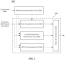
- FIG. 2 is a block diagram illustrating each component of a binaural renderer according to an exemplary embodiment of the present invention.
- the binaural renderer 200 may include a BRIR parameterization unit 300, a fast convolution unit 230, a late reverberation generation unit 240, a QTDL processing unit 250, and a mixer & combiner 260.
- the binaural renderer 200 generates a 3D audio headphone signal (that is, a 3D audio 2-channel signal) by performing binaural rendering of various types of input signals.
- the input signal may be an audio signal including at least one of the channel signals (that is, the loudspeaker channel signals), the object signals, and the HOA coefficient signals.
- the binaural renderer 200 when the binaural renderer 200 includes a particular decoder, the input signal may be an encoded bitstream of the aforementioned audio signal.
- the binaural rendering converts the decoded input signal into the binaural downmix signal to make it possible to experience a surround sound at the time of hearing the corresponding binaural downmix signal through a headphone.
- the binaural renderer 200 may perform the binaural rendering by using binaural room impulse response (BRIR) filter.
- BRIR binaural room impulse response
- the binaural rendering is M-to-O processing for acquiring O output signals for the multi-channel input signals having M channels.
- Binaural filtering may be regarded as filtering using filter coefficients corresponding to each input channel and each output channel during such a process.
- various filter sets representing transfer functions up to locations of left and right ears from a speaker location of each channel signal may be used.
- a transfer function measured in a general listening room, that is, a reverberant space among the transfer functions is referred to as the binaural room impulse response (BRIR).
- the BRIR contains information of the reproduction space as well as directional information.
- the BRIR may be substituted by using the HRTF and an artificial reverberator.
- the binaural rendering using the BRIR is described, but the present invention is not limited thereto, and the present invention may be applied even to the binaural rendering using various types of FIR filters including HRIR and HRTF by a similar or a corresponding method.
- the present invention can be applied to various forms of filterings for input signals as well as the binaural rendering for the audio signals.
- the apparatus for processing an audio signal may indicate the binaural renderer 200 or the binaural rendering unit 220, which is illustrated in FIG. 2 , as a narrow meaning.
- the apparatus for processing an audio signal may indicate the audio signal decoder of FIG. 1 , which includes the binaural renderer, as a broad meaning.
- an exemplary embodiment of the multi-channel input signals will be primarily described, but unless otherwise described, a channel, multi-channels, and the multi-channel input signals may be used as concepts including an object, multi-objects, and the multi-object input signals, respectively.
- the multi-channel input signals may also be used as a concept including an HOA decoded and rendered signal.
- the binaural renderer 200 may perform the binaural rendering of the input signal in the QMF domain. That is to say, the binaural renderer 200 may receive signals of multi-channels (N channels) of the QMF domain and perform the binaural rendering for the signals of the multi-channels by using a BRIR subband filter of the QMF domain.
- N channels multi-channels
- the binaural rendering in the QMF domain may be expressed by an equation given below.
- m is L (left) or R (right)
- b k , i m l is obtained by converting the time domain BRIR filter into the subband filter of the QMF domain.
- the binaural rendering may be performed by a method that divides the channel signals or the object signals of the QMF domain into a plurality of subband signals and convolutes the respective subband signals with BRIR subband filters corresponding thereto, and thereafter, sums up the respective subband signals convoluted with the BRIR subband filters.
- the BRIR parameterization unit 300 converts and edits BRIR filter coefficients for the binaural rendering in the QMF domain and generates various parameters.
- the BRIR parameterization unit 300 receives time domain BRIR filter coefficients for multi-channels or multi-objects, and converts the received time domain BRIR filter coefficients into QMF domain BRIR filter coefficients.
- the QMF domain BRIR filter coefficients include a plurality of subband filter coefficients corresponding to a plurality of frequency bands, respectively.
- the subband filter coefficients indicate each BRIR filter coefficients of a QMF-converted subband domain.
- the subband filter coefficients may be designated as the BRIR subband filter coefficients.
- the BRIR parameterization unit 300 may edit each of the plurality of BRIR subband filter coefficients of the QMF domain and transfer the edited subband filter coefficients to the fast convolution unit 230, and the like.
- the BRIR parameterization unit 300 may be included as a component of the binaural renderer 200 and, otherwise provided as a separate apparatus.
- a component including the fast convolution unit 230, the late reverberation generation unit 240, the QTDL processing unit 250, and the mixer & combiner 260, except for the BRIR parameterization unit 300 may be classified into a binaural rendering unit 220.
- the BRIR parameterization unit 300 may receive BRIR filter coefficients corresponding to at least one location of a virtual reproduction space as an input. Each location of the virtual reproduction space may correspond to each speaker location of a multi-channel system. According to an exemplary embodiment, each of the BRIR filter coefficients received by the BRIR parameterization unit 300 may directly match each channel or each object of the input signal of the binaural renderer 200. On the contrary, according to another exemplary embodiment of the present invention, each of the received BRIR filter coefficients may have an independent configuration from the input signal of the binaural renderer 200.
- At least a part of the BRIR filter coefficients received by the BRIR parameterization unit 300 may not directly match the input signal of the binaural renderer 200, and the number of received BRIR filter coefficients may be smaller or larger than the total number of channels and/or objects of the input signal.
- the BRIR parameterization unit 300 converts and edits the BRIR filter coefficients corresponding to each channel or each object of the input signal of the binaural renderer 200 to transfer the converted and edited BRIR filter coefficients to the binaural rendering unit 220.
- the corresponding BRIR filter coefficients may be a matching BRIR or a fallback BRIR selected from BRIR filter set for each channel or each object.
- the BRIR matching may be determined whether BRIR filter coefficients targeting the location of each channel or each object are present in the virtual reproduction space. In this case, positional information of each channel (or object) may be obtained from an input parameter which signals the channel arrangement.
- the BRIR filter coefficients may be the matching BRIR of the input signal.
- the BRIR parameterization unit 300 may provide BRIR filter coefficients, which target a location most similar to the corresponding channel or object, as the fallback BRIR for the corresponding channel or object.
- the corresponding BRIR filter coefficients may be selected.
- BRIR filter coefficients having the same altitude as and an azimuth deviation within +/- 20-from the desired position may be selected.
- BRIR filter coefficients corresponding thereto are not present, BRIR filter coefficients having a minimum geometric distance from the desired position in a BRIR filter set may be selected. That is, BRIR filter coefficients that minimize a geometric distance between the position of the corresponding BRIR and the desired position may be selected.
- the position of the BRIR represents a position of the speaker corresponding to the relevant BRIR filter coefficients.
- the geometric distance between both positions may be defined as a value obtained by aggregating an absolute value of an altitude deviation and an absolute value of an azimuth deviation between both positions.
- the position of the BRIR filter set may be matched up with the desired position.
- the interpolated BRIR filter coefficients may be regarded as a part of the BRIR filter set. That is, in this case, it may be implemented that the BRIR filter coefficients are always present at the desired position.
- the BRIR filter coefficients corresponding to each channel or each object of the input signal may be transferred through separate vector information m conv .
- the vector information m conv indicates the BRIR filter coefficients corresponding to each channel or object of the input signal in the BRIR filter set. For example, when BRIR filter coefficients having positional information matching with positional information of a specific channel of the input signal are present in the BRIR filter set, the vector information m conv indicates the relevant BRIR filter coefficients as BRIR filter coefficients corresponding to the specific channel.
- the vector information m conv indicates fallback BRIR filter coefficients having a minimum geometric distance from positional information of the specific channel as the BRIR filter coefficients corresponding to the specific channel when the BRIR filter coefficients having positional information matching positional information of the specific channel of the input signal are not present in the BRIR filter set. Accordingly, the parameterization unit 300 may determine the BRIR filter coefficients corresponding to each channel or object of the input audio signal in the entire BRIR filter set by using the vector information m conv .
- the BRIR parameterization unit 300 converts and edits all of the received BRIR filter coefficients to transfer the converted and edited BRIR filter coefficients to the binaural rendering unit 220.
- a selection procedure of the BRIR filter coefficients (alternatively, the edited BRIR filter coefficients) corresponding to each channel or each object of the input signal may be performed by the binaural rendering unit 220.
- the BRIR parameterization unit generates the truncated subband filter (the front subband filter) coefficients for each subband of the first subband group and transfers the front subband filter coefficients to the fast convolution unit.
- the fast convolution unit performs the VOFF processing of the subband signals of the first subband group by using the received front subband filter coefficients.
- a late reverberation proceesing of the subband signals of the first subband group may be additionally performed by the late reverberation generation unit.
- the BRIR parameterization unit obtains at least one parameter from each of the subband filter coefficients of the second subband group and transfers the obtained parameter to the QTDL processing unit.
- the QTDL processing unit performs tap-delay line filtering of each subband signal of the second subband group as described below by using the obtained parameter.
- the predetermined frequency (QMF band i) for distinguishing the first subband group and the second subband group may be determined based on a predetermined constant value or determined according to a bitstream characteristic of the transmitted audio input signal.
- the second subband group may be set to correspond to an SBR bands.
- the plurality of subbands may be classified into three subband groups based on a predetermined first frequency band (QMF band i) and a second frequency band (QMF band j) as illustrated in FIG. 3 . That is, the plurality of subbands may be classified into a first subband group Zone 1 which is a low-frequency zone equal to or lower than the first frequency band, a second subband group Zone 2 which is an intermediate-frequency zone higher than the first frequency band and equal to or lower than the second frequency band, and a third subband group Zone 3 which is a high-frequency zone higher than the second frequency band.
- a first subband group Zone 1 which is a low-frequency zone equal to or lower than the first frequency band
- a second subband group Zone 2 which is an intermediate-frequency zone higher than the first frequency band and equal to or lower than the second frequency band
- a third subband group Zone 3 which is a high-frequency zone higher than the second frequency band.
- the first subband group may include a total of 32 subbands having indexes 0 to 31
- the second subband group may include a total of 16 subbands having indexes 32 to 47
- the third subband group may include subbands having residual indexes 48 to 63.
- the subband index has a lower value as a subband frequency becomes lower.
- a first frequency band (QMF band i) is set as a subband of an index kConv-1 and a second frequency band (QMF band j) is set as a subband of an index kMax-1.
- the values of the information (kMax) of the number of frequency bands and the information (kConv) of the number of frequency bands to perform the convolution may vary by a sampling frequency of an original BRIR input, a sampling frequency of an input audio signal, and the like.
- the length of the rear subband filter Pk may also be determined based on the parameters extracted from the original subband filter as well as the front subband filter Fk. That is, the lengths of the front subband filter and the rear subband filter of each subband are determined based at least in part on the characteristic information extracted in the corresponding subband filter. For example, the length of the front subband filter may be determined based on first reverberation time information of the corresponding subband filter, and the length of the rear subband filter may be determined based on second reverberation time information.
- the front subband filter may be a filter at a truncated front part based on the first reverberation time information in the original subband filter
- the rear subband filter may be a filter at a rear part corresponding to a zone between a first reverberation time and a second reverberation time as a zone which follows the front subband filter.
- the first reverberation time information may be RT20
- the second reverberation time information may be RT60, but the present invention is not limited thereto.
- a part where an early reflections sound part is switched to a late reverberation sound part is present within a second reverberation time. That is, a point is present, where a zone having a deterministic characteristic is switched to a zone having a stochastic characteristic, and the point is called a mixing time in terms of the BRIR of the entire band.
- a zone before the mixing time information providing directionality for each location is primarily present, and this is unique for each channel.
- the late reverberation part has a common feature for each channel, it may be efficient to process a plurality of channels at once. Accordingly, the mixing time for each subband is estimated to perform the fast convolution through the VOFF processing before the mixing time and perform processing in which a common characteristic for each channel is reflected through the late reverberation processing after the mixing time.
- the length of the VOFF processing part that is, the length of the front subband filter may be longer or shorter than the length corresponding to the mixing time according to complexity-quality control.
- each subband filter in addition to the aforementioned truncation method, when a frequency response of a specific subband is monotonic, a modeling of reducing the filter of the corresponding subband to a low order is available.
- FIR filter modeling using frequency sampling there is FIR filter modeling using frequency sampling, and a filter minimized from a least square viewpoint may be designed.
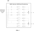
- FIG. 4 is a diagram more specifically illustrating QTDL processing according to the exemplary embodiment of the present invention.
- the QTDL processing unit 250 performs subband-specific filtering of multi-channel input signals X0, X1, ..., X_M-1 by using the one-tap-delay line filter.
- the one-tap-delay line filter may perform processing for each QMF subband.
- the one-tap-delay line filter performs the convolution by using only one tap with respect to each channel signal.
- the used tap may be determined based on the parameter directly extracted from the BRIR subband filter coefficients corresponding to the relavant subband signal.
- the parameter includes delay information for the tap to be used in the one-tap-delay line filter and gain information corresponding thereto.
- L_0, L_1, ... L_M-1 represent delays for the BRIRs with respect to M channels (input channels)-left ear (left output channel), respectively
- R_0, R_1, ..., R_M-1 represent delays for the BRIRs with respect to M channels (input channels)-right ear (right output channel), respectively.
- the delay information represents positional information for the maximum peak in the order of an absolution value, the value of a real part, or the value of an imaginary part among the BRIR subband filter coefficients.
- G_L_0, G_L_1, ..., G_L_M-1 represent gains corresponding to respective delay information of the left channel and G_R_0, G_R_1, ..., G_R_M-1 represent gains corresponding to the respective delay information of the right channels, respectively.
- Each gain information may be determined based on the total power of the corresponding BRIR subband filter coefficients, the size of the peak corresponding to the delay information, and the like. In this case, as the gain information, the weighted value of the corresponding peak after energy compensation for whole subband filter coefficients may be used as well as the corresponding peak value itself in the subband filter coefficients. The gain information is obtained by using both the real-number of the weighted value and the imaginary-number of the weighted value for the corresponding peak.
- the QTDL processing may be performed only with respect to input signals of high-frequency bands, which are classified based on the predetermined constant or the predetermined frequency band, as described above.
- the high-frequency bands may correspond to the SBR bands.
- the spectral band replication (SBR) used for efficient encoding of the high-frequency bands is a tool for securing a bandwidth as large as an original signal by re-extending a bandwidth which is narrowed by throwing out signals of the high-frequency bands in low-bit rate encoding.
- the high-frequency bands are generated by using information of low-frequency bands, which are encoded and transmitted, and additional information of the high-frequency band signals transmitted by the encoder.
- the SBR bands are the high-frequency bands, and as described above, reverberation times of the corresponding frequency bands are very short. That is, the BRIR subband filters of the SBR bands have small effective information and a high decay rate. Accordingly, in BRIR rendering for the high-frequency bands corresponding to the SBR bands, performing the rendering by using a small number of effective taps may be still more effective in terms of a computational complexity to the sound quality than performing the convolution.
- the plurality of channel signals filtered by the one-tap-delay line filter is aggregated to the 2-channel left and right output signals Y_L and Y_R for each subband.
- the parameter (QTDL parameter) used in each one-tap-delay line filter of the QTDL processing unit 250 may be stored in the memory during an initialization process for the binaural rendering and the QTDL processing may be performed without an additional operation for extracting the parameter.
- FIG. 5 is a block diagram illustrating respective components of a BRIR parameterization unit according to an exemplary embodimentof the present invention.
- the BRIR parameterization unit 300 may include an VOFF parameterization unit 320, a late revereberation parameterization unit 360, and a QTDL parameterization unit 380.
- the BRIR parameterization unit 300 receives a BRIR filter set of the time domain as an input and each sub-unit of the BRIR parameterization unit 300 generate various parameters for the binaural rendering by using the received BRIR filter set.
- the BRIR parameterization unit 300 may additionally receive the control parameter and generate the parameter based on the receive control parameter.
- the VOFF parameterization unit 320 generates truncated subband filter coefficients required for variable order filtering in frequency domain (VOFF) and the resulting auxiliary parameters. For example, the VOFF parameterization unit 320 calculates frequency band-specific reverberation time information, filter order information, and the like which are used for generating the truncated subband filter coefficients and determines the size of a block for performing block-wise fast Fourier transform for the truncated subband filter coefficients. Some parameters generated by the VOFF parameterization unit 320 may be transmitted to the late reverberation parameterization unit 360 and the QTDL parameterization unit 380.
- the transferred parameters are not limited to a final output value of the VOFF parameterization unit 320 and may include a parameter generated in the meantime according to processing of the VOFF parameterization unit 320, that is, the truncated BRIR filter coefficients of the time domain, and the like.
- the late reverberation parameterization unit 360 generates a parameter required for late reverberation generation.
- the late reverberation parameterization unit 360 may generate the downmix subband filter coefficients, the IC (Interaural Coherence) value, and the like.
- the QTDL parameterization unit 380 generates a parameter (QTDL parameter) for QTDL processing.
- the QTDL parameterization unit 380 receives the subband filter coefficients from the late reverberation parameterization unit 320 and generates delay information and gain information in each subband by using the received subband filter coefficients.
- the QTDL parameterization unit 380 may receive information kMax of the number of frequency bands for performing the binaural rendering and information kConv of the number of frequency bands for performing the convolution as the control parameters and generate the delay information and the gain information for each frequency band of a subband group having kMax and kConv as boundaries.
- the QTDL parameterization unit 380 may be provided as a component included in the VOFF parameterization unit 320.
- the parameters generated in the VOFF parameterization unit 320, the late reverberation parameterization unit 360, and the QTDL parameterization unit 380, respectively are transmitted to the binaural rendering unit (not illustrated).
- the later reverberation parameterization unit 360 and the QTDL parameterization unit 380 may determine whether the parameters are generated according to whether the late reverberation processing and the QTDL processing are performed in the binaural rendering unit, respectively.
- the late reverberation parameterization unit 360 and the QTDL parameterization unit 380 corresponding thereto may not generate the parameters or not transmit the generated parameters to the binaural rendering unit.
- FIG. 6 is a block diagram illustrating respective components of a VOFF parameterization unit of the present invention.
- the VOFF parameterization unit 320 may include a propagation time calculating unit 322, a QMF converting unit 324, and an VOFF parameter generating unit 330.
- the VOFF parameterization unit 320 performs a process of generating the truncated subband filter coefficients for VOFF processing by using the received time domain BRIR filter coefficients.
- the truncating lengths of the propagation time of all channels need to be the same as each other in order to perform the convolution by using the BRIR filter coefficients in which the propagation time is truncated at the time of performing the binaural rendering and compensate a final signal in which the binaural rendering is performed with a delay. Further, when the truncating is performed by applying the same propagation time information to each channel, error occurrence probabilities in the individual channels may be reduced.
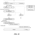
- the fast convolution unit multiplies the fast Fourier-transformed subframe (that is, FFT subframe) and the VOFF coefficients by each other to generate the filtered subframe.
- a complex multiplier (CMPY) of the fast convolution unit performs complex multiplication between the FFT subframe and the VOFF coefficients to generate the filtered subframe.
- the fast convolution unit inverse fast Fourier transforms each filtered subframe to generate the fast-convoluted subframe (Fast conv. subframe).
- the fast convolution unit overlap-adds at least one subframe (Fast conv. subframe) which is inverse fast-Fourier transformed to generate the filtered subband signal.
- the filtered subband signal may constitute an output audio signal in the corresponding subband.
- the filtered subframe may be aggregated into subframes for left and right output channels of the subframes for each channel in the same subband.
- the filtered subframes stored in the buffer are aggregated with the filtered subframe obtained through the complex multiplication between a third FFT subframe (FFT subframe 3) and the first VOFF coefficients (VOFF coef. 1) at a time corresponding to a third subframe and the inverse fast Fourier transform may be performed with respect to the aggregated subframe.
- FFT subframe 3 the third FFT subframe
- VOFF coef. 1 the first VOFF coefficients
- FIG. 11 illustrates a syntax of a binaural rendering function (S1100) according to an exemplary embodiment of the present invention.
- the binaural rendering according to the exemplary embodiment of the present invention may be performed by calling the binaural rendering function (S1100) of FIG. 11 .
- the binaural rendering function obtains file information of the BRIR filter coefficients through steps S1101 to S1104. Further, information 'bsNumBinauralDataRepresentation' indicating the total number of filter representations is received (S1110).
- the filter representation means a unit of independent binaural data included in a single binaural rendering syntax. Different filter representations may be assigned to proto-type BRIRs having different sample frequencies although being obtained in the same space. Further, even when the same proto-type BRIR is processed by different binaural parameterization units, different filter representations may be assigned to the same proto-type BRIR.
- steps S1111 to S1350 are repeated based on the received 'bsNumBinauralDataRepresentation' value.
- 'brirSamplingFrequencyIndex' which is an index for determining a sampling frequency value of the filter representation (that is, BRIR) is received (S1111).
- a value corresponding to the index may be obtained as the BRIR sampling frequency value by referring to a predefined table.
- the BRIR sampling frequency value 'brirSamplingFrequency' may be directly received from the bitstream.
- a BinauralFIRData() function (S1200) may be executed and therefore, the binaural renderer may receive proto-type FIR filter coefficients which are not transformed and edited.
- an FDBinauralRendererParam() function (S1300) may be executed and therefore, the binaural renderer may obtain the VOFF coefficients and the QTDL parameter in the frequency domain as the aforementioned exemplary embodiment.
- a TDBinauralRendererParam() function (S1350) may be executed and therefore, the binaural renderer receives the parameterized BRIR filter coefficients in the time domain.
- FIG. 12 illustrates a syntax of the BinauralFirData() function (S1200) for receiving the proto-type BRIR filter coefficients.
- BinauralFirData() is an FIR filter obtaining function for receiving the proto-type FIR filter coefficients which are not transformed and edited.
- the FIR filter obtaining function receives filter coefficient number information 'bsNumCoef' of the proto-type FIR filter (S1201). That is, 'bsNumCoef' may represent the length of the filter coefficients of the proto-type FIR filter.
- the FIR filter obtaining function receives FIR filter coefficients for each FIR filter index pos and a sample index i in the corresponding FIR filter (S1202 and S1203).
- the FIR filter index pos represents an index of the corresponding FIR filter pair (that is, a left/right output pair) in the number 'nBrirPairs' of transmitted binaural filter pairs.
- the number 'nBrirPairs' of transmitted binaural filter pairs may indicate the number of virtual speakers, the number of channels, or the number of HOA components to be filtered by the binaural filter pair.
- the index i indicates a sample index in each FIR filter coefficients having the length of 'bsNumCoefs'.
- the FIR filter obtaining function receives each of FIR filter coefficients of a left output channel (S1202) and FIR filter coefficients of a right output channel (S1203) for each index pos and i.
- the FIR filter obtaining function receives 'bsAllCutFreq' which is information indicating a maximum effective frequency of the FIR filter (S1210).
- the 'bsAllCutFreq' has a value of 0 when respective channels have different maximum effective frequencies and a value other than 0 when all channels have the same maximum effective frequency.
- the FIR filter obtaining function receives maximum effective frequency information 'bsCutFreqLeft[pos]' of the FIR filter of the left output channel and maximum effective frequency information 'bsCutFreqRight[pos]' of the right output channel for each FIR filter index pos (S1211 and S1212).
- each of the maximum effective frequency information 'bsCutFreqLeft[pos]' of the FIR filter of the left output channel and the maximum effective frequency information 'bsCutFreqRight[pos]' of the right output channel is allocated with the value of 'bsAllCutFreq' (S1213 and S1214).
- FIG. 13 illustrates a syntax of an FdBinauralRendererParam() function (S1300) according to an exemplary embodiment of the present invention.
- the FdBinauralRendererParam() function (S1300) is a frequency domain parameter obtaining function and receives various parameters for the frequency domain binaural filtering.
- information 'flagHrir' is received, which indicates whether impulse response (IR) filter coefficients input into the binaural renderer are the HRIR filter coefficients or the BRIR filter coefficients (S1302).
- 'flagHrir' may be determined based on whether the length of the proto-type BRIR filter coefficients received by the parameterization unit is more than a predetermined value.
- propagation time information 'dInit' indicating a time from an initial sample of the proto-type filter coefficients to a direct sound is received (S1303).
- the filter coefficients transferred by the parameterization unit may be filter coefficients of a remaining part after a part corresponding to the propagation time is removed from the proto-type filter coefficients.
- the frequency domain parameter obtaining function receives number information 'kMax' of frequency bands to perform the binaural rendering, number information 'kConv' of frequency bands to perform the convolution, and number information 'kAna' of frequency bands to perform late reverberation analysis (S1304, S1305, and S1306).
- the frequency domain parameter obtaining function executes a 'VoffBrirParam()' function to receive a VOFF parameter (S1400).
- an 'SfrBrirParam()' function is additionally executed, and as a result, a parameter for late reverberation processing may be received (S1450).
- the frequency domain parameter obtaining function executes a 'QtdIBrirParam()' function to receive a QTDL parameter (S1500).
- FIG. 14 illustrates a syntax of a VoffBrirParam() function (S1400) according to an exemplary embodiment of the present invention.
- the VoffBrirParam() function (S1400) is a VOFF parameter obtaining function and receives VOFF coefficients for VOFF processing and parameters associated therewith.
- the VOFF parameter obtaining function receives bit number information allocated to corresponding parameters. That is, bit number information 'nBitNFilter' of a filter order, bit number information 'nBitNFft' of the block length, and bit number information 'nBitNBlk' of a block number are received (S1401, S1402, and S1403).
- the VOFF parameter obtaining function repeatedly performs steps S1410 to S1423 with respect to each frequency band k to perform the binaural rendering.
- the subband index k has values from 0 to kMax-1.
- the VOFF parameter obtaining function receives filter order information 'nFilter[k]' of the corresponding subband k, block length (that is, FFT size) information 'nFft[k]' of the VOFF coefficients, and the block number information 'nBlk[k]' for each subband (S1410, S1411, and S1413).
- the block-wise VOFF coefficients set for each subband may be received and the predetermined block length, that is, the VOFF coefficients length may be determined as the value of power of 2.
- the VOFF parameter obtaining function receives the VOFF coefficients for each subband index k, a block index b, a BRIR index nr, and a frequency domain time slot index v in the corresponding block (S1420 to S1423).
- the BRIR index nr indicates the index of the corresponding BRIR filter pair in 'nBrirPairs' which is the number of transmitted binaural filter pairs.
- the number 'nBrirPairs' of transmitted binaural filter pairs may indicate the number of virtual speakers, the number of channels, or the number of HOA components to be filtered by the binaural filter pair.
- the index b represents an index of the corresponding VOFF coefficients block in 'nBlk[k]' which is the number of all blocks in the corresponding subband k.
- the index v represents a time slot index in each block having a length of 'fftLength'.
- the VOFF parameter obtaining function receives each of a left output channel VOFF coefficient (S1420) of a real value, a left output channel VOFF coefficient (S1421) of an imaginary value, a right output channel VOFF coefficient (S1422) of the real value, and a right output channel VOFF coefficient (S1423) of the imaginary value for each of the indexes k, b, nr and v.
- the binaural renderer of the present invention receives VOFF coefficients corresponding to each BRIR filter pair nr per block b of the fftLength length determined in the corresponding subband with respect to each subband k and performs the VOFF processing by using the received VOFF coefficients as described above.
- the VOFF coefficients are received with respect to all frequency bands (subband indexes 0 to kMax-1) to which the binaural rendering is performed. That is, the VOFF parameter obtaining function receives the VOFF coefficients for all subbands of a second subband group as well as a first subband group.
- the binaural renderer may perform the VOFF processing only with respect to the subbands of the first subband group.
- the binaural renderer may perform the VOFF processing with respect to each subband of the first subband group and the second subband group.
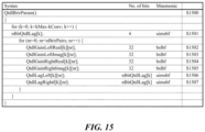
- FIG. 15 illustrates a syntax of a QtdlParam() function (S1500) according to an exemplary embodiment of the present invention.
- the QtdlParam() function (S1500) is a QTDL parameter obtaining function and receives at least one parameter for the QTDL processing.
- duplicated description of the same part as the exemplary embodiment of FIG. 14 will be omitted.
- the QTDL processing may be performed with respect to the second subband group, that is, each frequency band between the subband indexes kConv and kMax-1. Therefore, the QTDL parameter obtaining function repeatedly performs steps S1501 to S1507 kMax-kConv times with respect to the subband index k to receive the QTDL parameter for each subband of the second subband group.
- the QTDL parameter obtaining function receives bit number information 'nBitQtdlLag[k]' allocated to delay information of each subband (S1501).
- the QTDL parameter obtaining function receives the QTDL parameters, that is, gain information and delay information for each subband index k and the BRIR index nr (S1502 to S1507).
- the QTDL parameter obtaining function receives each of real value information (S1502) of a left output channel gain, imaginary value information (S1503) of the left output channel gain, real value information (S1504) of a right output channel gain, imaginary value information (S1505) of the right output channel gain, left output channel delay information (S1506), and right output channel delay information (S1507) for each of the indexes k and nr.
- the binaural renderer receives gain information of the real value, and gain information and delay information of the imaginary value of the left/right output channel for each subband k and each BRIR filter pair nr of the second subband group, and performs one-tap-delay line filtering for each subband signal of the second subband group by using the gain information of the real value, and the gain information and the delay information of the imaginary value.
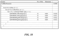
- the frequency domain parameter obtaining function receives bit number information 'nBitNFilter[n]' allocated at each filter order for the VBER index n (S1713) and receives each filter order information 'nFilter[n][k]' for a combination of the VBER index n and the subband index k (S1714). Meanwhile, although not illustrated in the syntax of FIG. 17 , the frequency domain parameter obtaining function may receive each filter order information 'nFilter[nr][k]' for a combination of the BRIR index nr and the subband index k.
- the present invention can be applied to various forms of apparatuses for processing a multimedia signal including an apparatus for processing an audio signal and an apparatus for processing a video signal, and the like.
- Embodiment 4 The method of embodiment 3, wherein the number of subbands of the high-frequency subband group performing the tap-delay line filtering is determined based on a difference between the number of frequency bands to perform the binaural rendering and the number of frequency bands to perform the convolution.
- Embodiment 5 The method of embodiment 3, wherein the parameter includes delay information extracted from the subband filter coefficients corresponding to each subband signal of the high-frequency group and gain information corresponding to the delay information.
- Embodiment 6 The method of embodiment 1, wherein when the type information indicates the FIR filter, the receiving the filter information step receives the proto-type filter coefficients corresponding to each subband signal of the input audio signal.
- Embodiment 7 An apparatus for processing an audio signal for performing binaural rendering of an input audio signal including at least one of a multi-channel signal and a multi-object signal, wherein the apparatus for processing an audio signal is configured to:
- Embodiment 8 A method for processing an audio signal, the method comprising:
- Embodiment 9 The method of embodiment 8, wherein the filter order is determined to be variable in a frequency domain.
- Embodiment 10 The method of embodiment 8, wherein the filter order is determined based on characteristic information extracted from filter coefficients of the corresponding subband.
- Embodiment 11 The method of embodiment 8, wherein the filter order has a single value for each subband.
- Embodiment 12 The method of embodiment 8, wherein the block length is determined as a value of power of 2 having an FFT length of the corresponding subband as an exponent value.
- Embodiment 13 The method of embodiment 8, wherein the number of blocks in a subband is determined based on a value obtained by dividing a reference filter length in the subband by the length according to the block length information, and wherein the reference filter length is determined based on a filter order of the corresponding subband.
- Embodiment 14 The method of embodiment 8, wherein the filter coefficients are received in a unit of a block having a length according to the block length information.
- Embodiment 15 An apparatus for processing an audio signal, the apparatus comprising:
- Embodiment 16 The apparatus of embodiment 15, wherein the filter order is determined to be variable in a frequency domain.
- Embodiment 17 The apparatus of embodiment 15, wherein the filter order is determined based on characteristic information extracted from filter coefficients of the corresponding subband.
- Embodiment 18 The apparatus of embodiment 15, wherein the filter order has a single value for each subband.
- Embodiment 19 The apparatus of embodiment 15, wherein the block length is determined as a value of power of 2 having an FFT length of the corresponding subband as an exponent value.
- Embodiment 20 The apparatus of embodiment 15, wherein the number of blocks in a subband is determined based on a value obtained by dividing a reference filter length in the subband by the length according to the block length information, and wherein the reference filter length is determined based on a filter order of the corresponding subband.
- Embodiment 21 The apparatus of embodiment 15, wherein the filter coefficients are received in a unit of a block having a length according to the block length information.
- Embodiment 22 A method for processing an audio signal in a plurality of subbands, the method comprising:
- Embodiment 23 An apparatus (220) for processing an audio signal in a plurality of subbands, the apparatus comprising:
Landscapes
- Engineering & Computer Science (AREA)
- Physics & Mathematics (AREA)
- Acoustics & Sound (AREA)
- Signal Processing (AREA)
- Multimedia (AREA)
- Mathematical Physics (AREA)
- Computational Linguistics (AREA)
- Health & Medical Sciences (AREA)
- Audiology, Speech & Language Pathology (AREA)
- Human Computer Interaction (AREA)
- Stereophonic System (AREA)
Applications Claiming Priority (7)
| Application Number | Priority Date | Filing Date | Title |
|---|---|---|---|
| US201461973868P | 2014-04-02 | 2014-04-02 | |
| KR20140081226 | 2014-06-30 | ||
| US201462019958P | 2014-07-02 | 2014-07-02 | |
| PCT/KR2015/003328 WO2015152663A2 (ko) | 2014-04-02 | 2015-04-02 | 오디오 신호 처리 방법 및 장치 |
| EP15774085.3A EP3128766A4 (de) | 2014-04-02 | 2015-04-02 | Verfahren und vorrichtung zur verarbeitung von tonsignalen |
| EP18178536.1A EP3399776B1 (de) | 2014-04-02 | 2015-04-02 | Verfahren und vorrichtung zur verarbeitung von tonsignalen |
| EP24151352.2A EP4329331B1 (de) | 2014-04-02 | 2015-04-02 | Audiosignalverarbeitungsverfahren und -vorrichtung |
Related Parent Applications (3)
| Application Number | Title | Priority Date | Filing Date |
|---|---|---|---|
| EP15774085.3A Division EP3128766A4 (de) | 2014-04-02 | 2015-04-02 | Verfahren und vorrichtung zur verarbeitung von tonsignalen |
| EP18178536.1A Division EP3399776B1 (de) | 2014-04-02 | 2015-04-02 | Verfahren und vorrichtung zur verarbeitung von tonsignalen |
| EP24151352.2A Division EP4329331B1 (de) | 2014-04-02 | 2015-04-02 | Audiosignalverarbeitungsverfahren und -vorrichtung |
Publications (2)
| Publication Number | Publication Date |
|---|---|
| EP4583542A2 true EP4583542A2 (de) | 2025-07-09 |
| EP4583542A3 EP4583542A3 (de) | 2025-08-06 |
Family
ID=80496119
Family Applications (2)
| Application Number | Title | Priority Date | Filing Date |
|---|---|---|---|
| EP25177503.7A Pending EP4583542A3 (de) | 2014-04-02 | 2015-04-02 | Audiosignalverarbeitungsverfahren und -vorrichtung |
| EP24151352.2A Active EP4329331B1 (de) | 2014-04-02 | 2015-04-02 | Audiosignalverarbeitungsverfahren und -vorrichtung |
Family Applications After (1)
| Application Number | Title | Priority Date | Filing Date |
|---|---|---|---|
| EP24151352.2A Active EP4329331B1 (de) | 2014-04-02 | 2015-04-02 | Audiosignalverarbeitungsverfahren und -vorrichtung |
Country Status (2)
| Country | Link |
|---|---|
| EP (2) | EP4583542A3 (de) |
| KR (4) | KR102741150B1 (de) |
Families Citing this family (1)
| Publication number | Priority date | Publication date | Assignee | Title |
|---|---|---|---|---|
| CN111107481B (zh) * | 2018-10-26 | 2021-06-22 | 华为技术有限公司 | 一种音频渲染方法及装置 |
Family Cites Families (7)
| Publication number | Priority date | Publication date | Assignee | Title |
|---|---|---|---|---|
| EP1025743B1 (de) * | 1997-09-16 | 2013-06-19 | Dolby Laboratories Licensing Corporation | Verwendung von filter-effekten bei stereo-kopfhörern zur verbesserung der räumlichen wahrnehmung einer schallquelle durch einen hörer |
| CA2621175C (en) * | 2005-09-13 | 2015-12-22 | Srs Labs, Inc. | Systems and methods for audio processing |
| CN101346895B (zh) * | 2005-10-26 | 2012-02-22 | 日本电气株式会社 | 回声抑制方法及设备 |
| WO2007080211A1 (en) * | 2006-01-09 | 2007-07-19 | Nokia Corporation | Decoding of binaural audio signals |
| KR100754220B1 (ko) | 2006-03-07 | 2007-09-03 | 삼성전자주식회사 | Mpeg 서라운드를 위한 바이노럴 디코더 및 그 디코딩방법 |
| US9496850B2 (en) | 2006-08-04 | 2016-11-15 | Creative Technology Ltd | Alias-free subband processing |
| US20110002469A1 (en) * | 2008-03-03 | 2011-01-06 | Nokia Corporation | Apparatus for Capturing and Rendering a Plurality of Audio Channels |
-
2015
- 2015-04-02 EP EP25177503.7A patent/EP4583542A3/de active Pending
- 2015-04-02 KR KR1020247026486A patent/KR102741150B1/ko active Active
- 2015-04-02 KR KR1020227026312A patent/KR102730463B1/ko active Active
- 2015-04-02 KR KR1020217004133A patent/KR102363475B1/ko active Active
- 2015-04-02 KR KR1020227004033A patent/KR102428066B1/ko active Active
- 2015-04-02 EP EP24151352.2A patent/EP4329331B1/de active Active
Also Published As
| Publication number | Publication date |
|---|---|
| EP4329331B1 (de) | 2025-06-18 |
| KR102741150B1 (ko) | 2024-12-11 |
| KR102428066B1 (ko) | 2022-08-02 |
| KR20210018559A (ko) | 2021-02-17 |
| EP4329331A3 (de) | 2024-05-08 |
| KR102363475B1 (ko) | 2022-02-16 |
| EP4583542A3 (de) | 2025-08-06 |
| KR20220025127A (ko) | 2022-03-03 |
| KR102730463B1 (ko) | 2024-11-15 |
| KR20240124433A (ko) | 2024-08-16 |
| KR20220113833A (ko) | 2022-08-16 |
| EP4329331A2 (de) | 2024-02-28 |
Similar Documents
| Publication | Publication Date | Title |
|---|---|---|
| EP3399776B1 (de) | Verfahren und vorrichtung zur verarbeitung von tonsignalen | |
| US10771910B2 (en) | Audio signal processing method and apparatus | |
| EP4329331B1 (de) | Audiosignalverarbeitungsverfahren und -vorrichtung |
Legal Events
| Date | Code | Title | Description |
|---|---|---|---|
| PUAI | Public reference made under article 153(3) epc to a published international application that has entered the european phase |
Free format text: ORIGINAL CODE: 0009012 |
|
| STAA | Information on the status of an ep patent application or granted ep patent |
Free format text: STATUS: REQUEST FOR EXAMINATION WAS MADE |
|
| REG | Reference to a national code |
Ref country code: DE Ref legal event code: R079 Free format text: PREVIOUS MAIN CLASS: H04S0007000000 Ipc: G10L0019008000 |
|
| PUAL | Search report despatched |
Free format text: ORIGINAL CODE: 0009013 |
|
| 17P | Request for examination filed |
Effective date: 20250520 |
|
| AC | Divisional application: reference to earlier application |
Ref document number: 3128766 Country of ref document: EP Kind code of ref document: P Ref document number: 3399776 Country of ref document: EP Kind code of ref document: P Ref document number: 4329331 Country of ref document: EP Kind code of ref document: P |
|
| AK | Designated contracting states |
Kind code of ref document: A2 Designated state(s): AL AT BE BG CH CY CZ DE DK EE ES FI FR GB GR HR HU IE IS IT LI LT LU LV MC MK MT NL NO PL PT RO RS SE SI SK SM TR |
|
| AK | Designated contracting states |
Kind code of ref document: A3 Designated state(s): AL AT BE BG CH CY CZ DE DK EE ES FI FR GB GR HR HU IE IS IT LI LT LU LV MC MK MT NL NO PL PT RO RS SE SI SK SM TR |
|
| RIC1 | Information provided on ipc code assigned before grant |
Ipc: G10L 19/008 20130101AFI20250627BHEP Ipc: H04S 3/00 20060101ALI20250627BHEP Ipc: H04R 3/04 20060101ALI20250627BHEP Ipc: H04S 7/00 20060101ALI20250627BHEP Ipc: G10L 19/02 20130101ALN20250627BHEP Ipc: G10L 19/16 20130101ALN20250627BHEP |
|
| STAA | Information on the status of an ep patent application or granted ep patent |
Free format text: STATUS: EXAMINATION IS IN PROGRESS |
|
| 17Q | First examination report despatched |
Effective date: 20260306 |