EP4583432A2 - Verfahren und vorrichtung zum empfangen von signalisierung und computerlesbares speichermedium - Google Patents
Verfahren und vorrichtung zum empfangen von signalisierung und computerlesbares speichermedium Download PDFInfo
- Publication number
- EP4583432A2 EP4583432A2 EP25178030.0A EP25178030A EP4583432A2 EP 4583432 A2 EP4583432 A2 EP 4583432A2 EP 25178030 A EP25178030 A EP 25178030A EP 4583432 A2 EP4583432 A2 EP 4583432A2
- Authority
- EP
- European Patent Office
- Prior art keywords
- csi
- ports
- resource
- multiplexing scheme
- code division
- Prior art date
- Legal status (The legal status is an assumption and is not a legal conclusion. Google has not performed a legal analysis and makes no representation as to the accuracy of the status listed.)
- Pending
Links
Images


Classifications
-
- H—ELECTRICITY
- H04—ELECTRIC COMMUNICATION TECHNIQUE
- H04L—TRANSMISSION OF DIGITAL INFORMATION, e.g. TELEGRAPHIC COMMUNICATION
- H04L5/00—Arrangements affording multiple use of the transmission path
- H04L5/003—Arrangements for allocating sub-channels of the transmission path
-
- H—ELECTRICITY
- H04—ELECTRIC COMMUNICATION TECHNIQUE
- H04J—MULTIPLEX COMMUNICATION
- H04J13/00—Code division multiplex systems
- H04J13/0007—Code type
- H04J13/004—Orthogonal
-
- H—ELECTRICITY
- H04—ELECTRIC COMMUNICATION TECHNIQUE
- H04L—TRANSMISSION OF DIGITAL INFORMATION, e.g. TELEGRAPHIC COMMUNICATION
- H04L1/00—Arrangements for detecting or preventing errors in the information received
- H04L1/02—Arrangements for detecting or preventing errors in the information received by diversity reception
- H04L1/06—Arrangements for detecting or preventing errors in the information received by diversity reception using space diversity
-
- H—ELECTRICITY
- H04—ELECTRIC COMMUNICATION TECHNIQUE
- H04L—TRANSMISSION OF DIGITAL INFORMATION, e.g. TELEGRAPHIC COMMUNICATION
- H04L5/00—Arrangements affording multiple use of the transmission path
-
- H—ELECTRICITY
- H04—ELECTRIC COMMUNICATION TECHNIQUE
- H04L—TRANSMISSION OF DIGITAL INFORMATION, e.g. TELEGRAPHIC COMMUNICATION
- H04L5/00—Arrangements affording multiple use of the transmission path
- H04L5/003—Arrangements for allocating sub-channels of the transmission path
- H04L5/0048—Allocation of pilot signals, i.e. of signals known to the receiver
-
- H—ELECTRICITY
- H04—ELECTRIC COMMUNICATION TECHNIQUE
- H04B—TRANSMISSION
- H04B7/00—Radio transmission systems, i.e. using radiation field
- H04B7/02—Diversity systems; Multi-antenna system, i.e. transmission or reception using multiple antennas
- H04B7/04—Diversity systems; Multi-antenna system, i.e. transmission or reception using multiple antennas using two or more spaced independent antennas
- H04B7/06—Diversity systems; Multi-antenna system, i.e. transmission or reception using multiple antennas using two or more spaced independent antennas at the transmitting station
-
- H—ELECTRICITY
- H04—ELECTRIC COMMUNICATION TECHNIQUE
- H04L—TRANSMISSION OF DIGITAL INFORMATION, e.g. TELEGRAPHIC COMMUNICATION
- H04L25/00—Baseband systems
- H04L25/02—Details ; arrangements for supplying electrical power along data transmission lines
- H04L25/0202—Channel estimation
- H04L25/0224—Channel estimation using sounding signals
Definitions
- the User Equipment may not implement transmission and reception simultaneously, while in a full-duplex FDD manner, there is no such limit.
- FIG. 2 is a schematic diagram of a frame structure type 2. As shown in FIG. 2 , the description of the frame structure type 2 is provided as follows.
- Uplink-downlink configuration of a cell changes among frames, and uplink-downlink transmission occurs in subframes of the frames.
- Uplink-downlink configuration of a present frame is obtained by high-layer signaling.
- a signal transmitted in each slot is described with one or more resource grids.
- a resource grid consists of N RB DL N sc RB subcarriers and N symb DL OFDM symbols, where N RB DL represents the number of Physical Resource Blocks (PRBs) or Resource Blocks (RBs), N sc RB represents the number of subcarriers in the RBs, and N symb DL represents the number of the OFDM symbols in the slot.
- Table 2 shows PRB parameters, and the number of OFDM symbols and the number of subcarriers on an RB are shown in Table 2.
- Table 3 shows OFDM symbol parameters and lengths of the CPs.
- the number N RB DL of the PRBs is determined by a downlink transmission bandwidth configured by a cell and has a minimum value of 6 and a maximum value of 110.
- the same PRB on two continuous slots on the same subframe is referred to as a PRB pair.
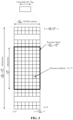
- FIG. 3 is a schematic diagram of a downlink resource grid.
- RE Resource Element
- An antenna port is defined as a channel through which a symbol transmitted on the antenna port passes and may be conjectured by a channel through which another symbol transmitted on the same port passes.
- An antenna port is also defined with a corresponding serial number for distinguishing between antenna ports and an index of the antenna port.
- a downlink physical channel corresponds to a set of REs and is arranged to carry information from an upper layer.
- Downlink physical channels include: a Physical Downlink Shared Channel (PDSCH), a Physical Multicast Channel (PMCH), a Physical Broadcast Channel (PBCH), a Physical Control Format Indicator Channel (PCFICH), a Physical Downlink Control Channel (PDCCH), a Physical Hybrid Automatic Repeat reQuest Indicator Channel (PHICH), and an Enhanced PDCCH (EPDCCH).
- PDSCH Physical Downlink Shared Channel
- PMCH Physical Multicast Channel
- PBCH Physical Broadcast Channel
- PCFICH Physical Control Format Indicator Channel
- PDCCH Physical Downlink Control Channel
- PHICH Physical Hybrid Automatic Repeat reQuest Indicator Channel
- EPDCCH Enhanced PDCCH
- a downlink physical signal corresponds to a set of REs, is used by a physical layer, and is arranged to not carry upper-layer information.
- Downlink physical signals include: a Reference Signal (RS), a synchronization signal, and a discovery signal.
- RS Reference Signal
- RSs are also referred to as pilots, and include the following types: Cell-specific Reference Signals (CRSs), Multimedia Broadcast Single Frequency Network (MBSFN) RSs, UE-specific RSs (Demodulation Reference Signals (DMRSs)), positioning RSs, and CSI-RSs, where the UE-specific RSs further include the following two types: UE-specific RSs associated with PDSCH and DMRSs associated with EPDCCH.
- CRSs Cell-specific Reference Signals
- MMSFN Multimedia Broadcast Single Frequency Network
- DMRSs Demodulation Reference Signals
- positioning RSs and CSI-RSs
- CSI-RSs where the UE-specific RSs further include the following two types: UE-specific RSs associated with PDSCH and DMRSs associated with EPDCCH.
- a CSI-RS is used for UE to predict a channel state.
- a CSI-RS transmitted with Non-Zero Power is referred to as an NZP CSI-RS.
- NZP CSI-RS Non-Zero Power
- ZP Zero Power
- the CSI-RS is referred to as a ZP CSI-RS
- a corresponding RE set is referred to as a ZP CSI-RS resource.
- ZP transmission of a CSI-RS is used, and at this time, a corresponding RE set is referred to as a CSI-Interference Measurement (CSI-IM) resource.
- CSI-IM CSI-Interference Measurement
- a CSI-RS configuration is used to indicate an RE mapped by a CSI-RS, i.e., an RE for transmitting the CSI-RS, and a CSI-RS configuration serial number is used to distinguish different CSI-RS configurations.
- An RE set for transmitting or mapping a CSI-RS under a CSI-RS configuration is referred to as a CSI-RS resource pattern.
- a CSI-RS subframe configuration is used to indicate a subframe where a CSI-RS is transmitted.
- a CSI-RS configuration is a CSI-RS configuration under a certain number of antenna ports, for example, a CSI-RS configuration corresponding to 8 antenna ports and with a configuration serial number 0 (an 8-port CSI-RS config #0).
- a CSI-RS resource pattern is a CSI-RS resource pattern under a certain number of antenna ports, for example, a CSI-RS resource pattern corresponding to 8 antenna ports and with an index number of 0 (an 8-port CSI-RS resource pattern #0).
- a configuration serial number is usually an index number.
- An RE set for transmitting or mapping CSI-RSs with part of the ports under a CSI-RS configuration is referred to as an RS resource pattern with part of ports, for example, an RS resource pattern with port serial numbers of ⁇ 15, 16, 17, 18 ⁇ .
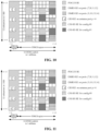
- a related technology supports CSI-RSs with 1, 2, 4, or 8 ports, and CSI-RS resource patterns with these numbers of ports are repeated on each PRB pair within a bandwidth range in a transmission subframe.
- All RE sets configured as CSI-RS resource patterns with different numbers of ports are the same, that is, all RE sets configured as 2-port CSI-RS resource patterns are equal to all RE sets configured as 4-port CSI-RS resource patterns and equal to all RE sets configured as 8-port CSI-RS resource patterns.
- all RE sets configured as CSI-RS resource patterns with different numbers of ports are the same, and the number of REs on a PRB is 40.
- FIG. 4 is a resource pattern of a 4-port CSI-RS on an RB pair.
- FIG. 5 is a resource pattern of an 8-port CSI-RS on an RB pair.
- the number of ports in a group is N
- a CSI-RS sequence is ⁇ r 0 ,r 1 , ⁇ ,r N-1 ⁇
- a base station notifies UE of information about a CSI-RS through upper-layer signaling, and the information includes: a CSI-RS resource configuration identity, the number of ports for the CSI-RS, CSI-RS configuration, and CSI-RS subframe configuration.
- a CRS may be arranged to not only measure a channel state but also receive an estimation of a channel coefficient during demodulation.
- an overhead is sharply increased. Therefore, CRS is no longer used to measure channel states when the number of ports is 8, and instead, CSI-RSs which are low in RS density and low in overhead are used.
- technologies applied under a larger number of antenna ports for example, 12 or 16 ports, are to be developed, and measurement over channel states under the larger number of ports is involved.
- the related technology may not support 12 or 16-port CSI-RS transmission.
- the number of the ports is increased to 12 or 16, there may be problems of high overhead, reduction in channel measurement performance, high UE complexity, and the like.
- a base station determines configuration information of a CSI-RS.
- the base station In S12, the base station generates signaling including the configuration information of the CSI-RS.
- the base station transmits the signaling including the configuration information of the CSI-RS.
- the configuration information includes: the number of ports, RS resource pattern information, and an inter-CSI-RS-port multiplexing scheme.
- the number of the ports is larger than 1, there are M candidate RS resource patterns for the CSI-RS, where M is an integer greater than 1.
- the M candidate RS resource patterns include that: when the number of the ports is larger than a first threshold value (TH1), at least two inter-CSI-RS-port multiplexing schemes are used for the M candidate RS resource patterns.
- TH1 a first threshold value
- an RS symbol of a port is transmitted by one port, and data symbols on a PDSCH are transmitted by multiple ports. If an RS symbol of one port is transmitted on an RE, all power on the RE may be used for transmission of the port, and is equivalent to a sum of powers for all ports transmitting data symbols on an RE; and if the power for transmitting an RS symbol by a port is excessively higher than power for transmitting data symbols by the same port, transmission accuracy of the RS symbol may be influenced.
- a code division multiplexing scheme is used for RS symbols of multiple ports, so that power may be fully utilized, and RS symbol transmission power of each port may be reduced.
- a smaller code division multiplexing length may be used; in the case that the number of the ports is increased, a larger code division multiplexing length may be used; and in the case that the number of the ports is larger, the number of the ports is split into several groups of a smaller number of ports sometimes, and a smaller code division multiplexing length is used for their RSs.
- the number of time-domain multiplexing OFDM symbols is increased; or the number of the time-domain multiplexing OFDM symbols is decreased; or, a frequency-domain multiplexing interval is increased; or, the frequency-domain multiplexing interval is decreased.
- the M candidate RS resource patterns include the following: the M candidate RS resource patterns are divided into two sets, a first multiplexing scheme is used for CSI-RS ports in the first pattern set, a second multiplexing scheme is used for CSI-RS ports in the second pattern set, and the first multiplexing scheme is different from the second multiplexing scheme.
- the number of ports in a group is large sometimes, a larger number of REs are occupied for their multiplexing, a large number of REs are required to be occupied, and then a multiplexing scheme with a larger number of OFDM symbols is required to be used or a multiplexing scheme with a decreased frequency-domain interval is used; and the number of ports in a group is small sometimes, a smaller number of REs are occupied for their multiplexing, a smaller number of REs are required to be occupied, and then a multiplexing scheme with a smaller number of OFDM symbols is required to be used or a multiplexing scheme with an increased frequency-domain interval is used.
- the M candidate RS resource patterns include that: the M candidate RS resource patterns are divided into two sets, a first multiplexing scheme is used for CSI-RS ports in the first pattern set, the first multiplexing scheme or a second multiplexing scheme is used for CSI-RS ports in the second pattern set, the first multiplexing scheme is different from the second multiplexing scheme, and the multiplexing scheme used for the CSI-RS ports of the second pattern set is configured via signaling of the base station.
- the number of ports in a group is large sometimes, a larger number of REs are occupied for multiplexing of the ports, a larger number of REs are required to be occupied, and then a multiplexing scheme with a larger number of OFDM symbols is required to be used or a multiplexing scheme with a decreased frequency-domain interval is used; and the number of ports in a group is small sometimes, a smaller number of REs are occupied for multiplexing of the ports, a smaller number of REs are required to be occupied, and then a multiplexing scheme with a smaller number of OFDM symbols is required to be used or a multiplexing scheme with an increased frequency-domain interval is used.
- the first multiplexing scheme is used for the CSI-RS ports of the first pattern set
- the first multiplexing scheme or the second multiplexing scheme is used for the CSI-RS ports of the second pattern set.
- an RS resource pattern corresponding to a larger code division multiplexing length may be used; and in the case that the number of the ports is large, the RS is split into several RSs with fewer ports sometimes, and an RS resource pattern corresponding to a smaller code division multiplexing length is used.
- the first multiplexing scheme is used for the CSI-RS ports of the first pattern set, and the first multiplexing scheme or the second multiplexing scheme is used for the CSI-RS ports of the second pattern set.
- the M candidate RS resource patterns include the following: the M candidate RS resource patterns are divided into three sets, a first multiplexing scheme is used for CSI-RS ports of the first pattern set, a second multiplexing scheme is used for CSI-RS ports of the second pattern set, the first multiplexing scheme or the second multiplexing scheme is used for CSI-RS ports of the third pattern set, the first multiplexing scheme is different from the second multiplexing scheme, and the multiplexing scheme used for the CSI-RS ports of the third pattern set is configured via signaling of the base station.
- the number of ports in a group is large sometimes, a larger number of REs are occupied for multiplexing of the ports, a larger number of REs are required to be occupied, and then a multiplexing scheme with a larger number of OFDM symbols is required to be used or a multiplexing scheme with a decreased frequency-domain interval is used; and the number of ports in a group is small sometimes, a smaller number of REs are occupied for multiplexing of the ports, a smaller number of REs are required to be occupied, and then a multiplexing scheme with a smaller number of OFDM symbols is required to be used or a multiplexing scheme with an increased frequency-domain interval is used.
- a smaller code division multiplexing length may be used; in the case that the number of the ports is increased, a larger code division multiplexing length may be used; and the in the case that the number of the port is larger, the RS is split into several RSs with fewer ports, and a smaller code division multiplexing length is used.
- Part of the patterns are applied to the condition of splitting into several RSs with fewer ports, part of the patterns are applied to the condition that the number of the ports is large, and part of the patterns are not only applied to the condition of splitting into several RSs with fewer ports but also applied to the condition that the number of the ports is large.
- the multiplexing scheme is a code division multiplexing scheme.
- the first code division multiplexing scheme is code division multiplexing with an orthogonal code length of 2
- the second code division multiplexing scheme is code division multiplexing with an orthogonal code length of 4.
- the number of REs configured for CSI-RS transmission of a frame structure type 1 and a frame structure type 2 is 40.
- available RS resource patterns are reduced.
- the M candidate RS resource patterns include that: in an RS resource pattern set, each RS resource pattern corresponds to two groups of ports, a first code division multiplexing scheme is used for the first group of ports, the first code division multiplexing scheme or a second code division multiplexing scheme is used for the second group of ports, the first code division multiplexing scheme is different from the second code division multiplexing scheme, and the code division multiplexing scheme used for the second group of ports is configured via signaling of the base station.
- the M candidate RS resource patterns include that: in an RS resource pattern set, each RS resource pattern corresponds to two groups of ports, a first code division multiplexing scheme or a second code division multiplexing scheme is used for the first group of ports, the first code division multiplexing scheme or the second code division multiplexing scheme is used for the second group of ports, the first code division multiplexing scheme is different from the second code division multiplexing scheme, the code division multiplexing scheme used for the first group of ports is configured via signaling of the base station, and the code division multiplexing scheme used for the second group of ports is configured by the signaling of the base station.
- the first mapping manner may achieve a channel estimation performance gain for code division multiplexing
- the second mapping manner does not require continuity of the subcarriers, has higher mapping flexibility, and may be compatible with a conventional 4-port RS pattern.
- the manner of mapping the code division multiplexed RS symbols in the same group to the REs is notified via the signaling to meet a requirement of a practical scenario.
- the M candidate RS resource patterns include that: the M candidate RS resource patterns are divided into two sets, in a first pattern set, a first mapping manner is used to map code division multiplexed RS symbols in a same group to REs, and in a second pattern set, a second mapping manner is used to map code division multiplexed RS symbols in a same group to REs, and the first mapping manner is different from the second mapping manner.
- the two sets correspond to different manners of mapping the RS symbols to the REs respectively to meet different requirements.
- the operation that the base station determines the configuration information of the CSI-RS includes that: when the inter-CSI-RS-port multiplexing scheme uses the code division multiplexing length of 4 and the ports are grouped for code division multiplexing, a port grouping manner is configured via signaling of the base station, the port grouping manner including two port grouping manners.
- the M candidate RS resource patterns include that: the M candidate RS resource patterns are divided into two sets, a first port grouping manner is used for CSI-RS ports in the first pattern set, a second port grouping manner is used for CSI-RS ports in the second pattern set, and the first port grouping manner is different from the second port grouping manner.
- FIG. 7 is a schematic diagram of a device for configuring a CSI-RS according to an embodiment of the invention.
- the device for configuring the CSI-RS provided by the embodiment is arranged at a base station and includes: a determination module 1101, a generation module 1102, and a transmission module 1103, where the determination module 1101 is arranged to determine configuration information of a CSI-RS; the generation module 1102 is arranged to generate signaling including the configuration information of the CSI-RS; and the transmission module 1103 is arranged to transmit the signaling including the configuration information of the CSI-RS, where the configuration information includes: the number of ports, RS resource pattern information and an inter-CSI-RS-port multiplexing scheme; and when the number of the ports is larger than 1, there exist M candidate RS resource patterns for the CSI-RS, where M is an integer greater than 1.
- the M candidate RS resource patterns include that: when the number of the ports is larger than a first threshold value, at least two inter-CSI-RS-port multiplexing schemes are used for the M candidate RS resource patterns.
- the M candidate RS resource patterns include the following: the M candidate RS resource patterns are divided into two sets, a first multiplexing scheme is used for CSI-RS ports of the first pattern set, a second multiplexing scheme is used for CSI-RS ports of the second pattern set, and the first multiplexing scheme is different from the second multiplexing scheme.
- the multiplexing scheme is a code division multiplexing scheme.
- the M candidate RS resource patterns include that: when the number of the ports is 12, in an RS resource pattern set, each RS resource pattern corresponds to two groups of ports, a first code division multiplexing scheme is used for the first group of ports, a second code division multiplexing scheme is used for the second group of ports, and the first code division multiplexing scheme is different from the second code division multiplexing scheme.
- the M candidate RS resource patterns include that: in an RS resource pattern set, the inter-CSI-RS-port multiplexing scheme uses a code division multiplexing length of 4, and code division multiplexed RS symbols of each group are mapped to REs on a PRB pair in a resource pattern under the number of the ports of 4.
- the transmission module is a communication component with an information transmission capability, for example, a transmitter
- the determination module and the generation module are components with an information processing capability, for example, a processor.
- the modules may be, for example, combinations of software and/or hardware capable of realizing certain functions.
- a base station determines configuration information of a CSI-RS at first, then generates signaling including the configuration information of the CSI-RS, and finally transmits the signaling including the configuration information of the CSI-RS.
- a bits are used to represent port number information
- b bits are used to represent RS resource pattern information
- a bits may be used to represent the port number information
- the port number information is indicated by using a bits
- the RS resource pattern information and the inter-CSI-RS-port multiplexing scheme are jointly indicated by using b bits.
- X bits may be used to represent joint coding of the port number information, the RS resource pattern information, and the inter-CSI-RS-port multiplexing scheme.
- the port number information, the RS resource pattern information, and the inter-CSI-RS-port multiplexing scheme are jointly indicated by using X bits.
- a bits may be used to represent the port number information
- b bits are used to represent the RS resource pattern information
- the RS resource pattern information prompts the inter-CSI-RS-port multiplexing scheme.
- the number of ports may be selected from ⁇ 1, 2, 4, 8, 12, 16 ⁇ .
- the M candidate RS resource patterns adopt at least two inter-CSI-RS-port code division multiplexing schemes, where M is an integer greater than 1.
- TH1 may be selected from ⁇ 4, 8, 12 ⁇ .
- the inter-CSI-RS-port code division multiplexing schemes include code division multiplexing with a length of 2, code division multiplexing with a length of 4, code division multiplexing in a time domain, code division multiplexing in a frequency domain, code division multiplexing in both the time domain and the frequency domain and a combination of the manners.
- the M candidate RS resource patterns are divided into two sets, a first multiplexing scheme is used for CSI-RS ports of the first pattern set, the first multiplexing scheme or a second multiplexing scheme is used for CSI-RS ports of the second pattern set, and the first multiplexing scheme is different from the second multiplexing scheme, where M is an integer greater than 1.
- the multiplexing scheme used for the CSI-RS ports of the second pattern set is configured via signaling of the base station.
- the first code division multiplexing scheme used for the CSI-RS ports of the first pattern sets uses a code division multiplexing length of 2
- the second code division multiplexing scheme used for the CSI-RS ports of the second pattern set uses a code division multiplexing length of 4
- the code division multiplexing scheme used for the CSI-RS ports of the third pattern set uses the code division multiplexing length of 2 or 4
- the first code division multiplexing scheme used for the CSI-RS ports of the first pattern set uses the code division multiplexing length of 4
- the second code division multiplexing scheme used for the CSI-RS ports of the second pattern set uses the code division multiplexing length of 2
- the code division multiplexing scheme used for the CSI-RS ports of the third pattern set uses the code division multiplexing length of 2 or 4, where the code division multiplexing length used for the CSI-RS ports of the third pattern set is configured via signaling of the base station.
- a second threshold value TH2
- M is an integer greater than 1.
- RS densities when TH2 is 8 and the number of the ports is 12, there are the following three types of RS densities: one RE in each PRB pair for each port, one RE in every two PRB pairs for each port, and two REs in every three PRB pairs for each port; and when TH2 is 8 and the number of the ports is 16, there are the following two types of RS densities: one RE in each PRB pair for each port and one RE in every two PRB pairs for each port.
- the third threshold value is 9.
- the fourth threshold value is 6.
- each RS resource pattern corresponds to an 8-port RS resource pattern
- an RS density is two REs in every three PRB pairs for each port
- different RS resource patterns correspond to different RS resource patterns under the number of the ports of 8.
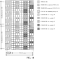
- FIG. 14 is a pattern with an RS density of one RE in every two PRB pairs for each port in the case of 12 ports.
- there are totally five patterns: CSI-RS RE for config #0, CSI-RS RE for config #1, CSI-RS RE for config #0 2, CSI-RS RE for config #3, and CSI-RS RE for config #4.
- each RS resource pattern corresponds to an 8-port RS resource pattern and two 2-port RS resource patterns
- the RS resource patterns with the two numbers of ports are located on the same two OFDM symbols and adj acent in frequency domain
- an RS density is one RE in each PRB pair for each port
- different RS resource patterns correspond to different combinations of 8-port RS resource patterns and 2-port RS resource patterns.
- FIG. 16 is a mapping of each group of code division multiplexed RS symbols onto REs of a PRB pair in a 4-port resource pattern.
- the ports are grouped as follows: ⁇ 15, 16, 19, 20 ⁇ , ⁇ 17, 18, 21, 22 ⁇ , ⁇ 23, 24, 27, 28 ⁇ and ⁇ 25, 26, 29, 30 ⁇ , and the code division multiplexed RS symbols of each group are mapped to REs of a PRB pair in a 4-port resource pattern.
- the first mapping manner is mapping the code division multiplexed RS symbols onto two continuous subcarriers
- the second mapping manner is mapping the code division multiplexed RS symbols onto two subcarriers having a frequency-domain difference value of 6 subcarriers.
- the first port grouping manner is as follows: ⁇ 15, 16, 17, 18 ⁇ , ⁇ 19, 20, 21, 22 ⁇ , ⁇ 23, 24, 25, 26 ⁇ and ⁇ 27, 28, 29, 30 ⁇ ; and the second port grouping manner is as follows: ⁇ 15, 16, 19, 20 ⁇ , ⁇ 17, 18, 21, 22 ⁇ , ⁇ 23, 24, 27, 28 ⁇ and ⁇ 25, 26, 29, 30 ⁇ .
- configuration information of a CSI-RS is determined.
- the signaling including the configuration information of the CSI-RS is transmitted.
- the storage medium may include, but not limited to: various media capable of storing program codes, such as a U disk, a Read-Only Memory (ROM), a Random Access Memory (RAM), a mobile hard disk, a magnetic disk or an optical disk.
- program codes such as a U disk, a Read-Only Memory (ROM), a Random Access Memory (RAM), a mobile hard disk, a magnetic disk or an optical disk.
- each module or each step of the invention may be implemented by a universal computing device, and the modules or steps may be concentrated on a single computing device or distributed on a network formed by a plurality of computing devices, and may alternatively be implemented by program codes executable by the computing devices, so that the modules or steps may be stored in a storage device for execution with the computing devices, the shown or described steps may be executed in sequences different from those described here in some circumstances, or may form each integrated circuit module respectively, or multiple modules or steps therein may form a single integrated circuit module for implementation.
- the invention is not limited to any specific hardware and software combination.
Landscapes
- Engineering & Computer Science (AREA)
- Signal Processing (AREA)
- Computer Networks & Wireless Communication (AREA)
- Mobile Radio Communication Systems (AREA)
- Circuits Of Receivers In General (AREA)
Applications Claiming Priority (3)
| Application Number | Priority Date | Filing Date | Title |
|---|---|---|---|
| CN201510624664.XA CN106559199A (zh) | 2015-09-25 | 2015-09-25 | 一种配置信道状态测量导频的方法及装置 |
| PCT/CN2016/095499 WO2017050065A1 (zh) | 2015-09-25 | 2016-08-16 | 一种配置信道状态测量导频的方法及装置 |
| EP16847947.5A EP3355507B1 (de) | 2015-09-25 | 2016-08-16 | Verfahren und vorrichtung zum konfigurieren eines kanalzustandsinformationsreferenzsignals |
Related Parent Applications (2)
| Application Number | Title | Priority Date | Filing Date |
|---|---|---|---|
| EP16847947.5A Division EP3355507B1 (de) | 2015-09-25 | 2016-08-16 | Verfahren und vorrichtung zum konfigurieren eines kanalzustandsinformationsreferenzsignals |
| EP16847947.5A Division-Into EP3355507B1 (de) | 2015-09-25 | 2016-08-16 | Verfahren und vorrichtung zum konfigurieren eines kanalzustandsinformationsreferenzsignals |
Publications (2)
| Publication Number | Publication Date |
|---|---|
| EP4583432A2 true EP4583432A2 (de) | 2025-07-09 |
| EP4583432A3 EP4583432A3 (de) | 2025-10-01 |
Family
ID=58385837
Family Applications (2)
| Application Number | Title | Priority Date | Filing Date |
|---|---|---|---|
| EP16847947.5A Active EP3355507B1 (de) | 2015-09-25 | 2016-08-16 | Verfahren und vorrichtung zum konfigurieren eines kanalzustandsinformationsreferenzsignals |
| EP25178030.0A Pending EP4583432A3 (de) | 2015-09-25 | 2016-08-16 | Verfahren und vorrichtung zum empfangen von signalisierung und computerlesbares speichermedium |
Family Applications Before (1)
| Application Number | Title | Priority Date | Filing Date |
|---|---|---|---|
| EP16847947.5A Active EP3355507B1 (de) | 2015-09-25 | 2016-08-16 | Verfahren und vorrichtung zum konfigurieren eines kanalzustandsinformationsreferenzsignals |
Country Status (4)
| Country | Link |
|---|---|
| US (2) | US11233611B2 (de) |
| EP (2) | EP3355507B1 (de) |
| CN (1) | CN106559199A (de) |
| WO (1) | WO2017050065A1 (de) |
Families Citing this family (16)
| Publication number | Priority date | Publication date | Assignee | Title |
|---|---|---|---|---|
| CN112910622B (zh) * | 2015-11-06 | 2021-11-30 | 中兴通讯股份有限公司 | 信道状态测量导频的配置方法及装置、解析方法及装置 |
| EP3520303B1 (de) * | 2016-09-28 | 2021-01-13 | NTT DoCoMo, Inc. | Drahtloskommunikationsverfahren zur übertragung einer referenzsignalressourcenanzeige |
| WO2018058456A1 (zh) * | 2016-09-29 | 2018-04-05 | 华为技术有限公司 | 信道状态信息参考信号发送方法与接收方法及设备 |
| RU2019137014A (ru) * | 2016-09-30 | 2019-12-19 | Телефонактиеболагет Лм Эрикссон (Пабл) | Cdm8, основанные на csi-rs структурах, для mimo |
| CN108023699B (zh) * | 2016-11-04 | 2020-12-15 | 华为技术有限公司 | 信号传输方法和装置 |
| CN108400851B (zh) * | 2017-02-04 | 2022-08-19 | 中兴通讯股份有限公司 | 配置信息处理方法及装置、基站、终端 |
| CN108111269B (zh) | 2017-05-05 | 2023-01-10 | 中兴通讯股份有限公司 | 一种信道状态信息导频传输方法与装置 |
| JP7263315B2 (ja) | 2017-08-03 | 2023-04-24 | 日本電気株式会社 | ネットワークデバイス、端末デバイス、及び方法 |
| CN109391391B (zh) * | 2017-08-08 | 2020-04-17 | 维沃移动通信有限公司 | 一种用于传输参考信号的方法及装置 |
| CN109391411B (zh) * | 2017-08-10 | 2021-03-02 | 电信科学技术研究院 | 一种导频配置方法、信道测量方法及通信设备 |
| CN108111273B (zh) * | 2017-08-11 | 2021-11-02 | 中兴通讯股份有限公司 | 参考信号的传输方法及装置 |
| CN110071749B (zh) * | 2018-01-22 | 2021-08-31 | 华为技术有限公司 | 一种天线选择指示方法、装置和系统 |
| EP3874607B1 (de) | 2018-11-01 | 2023-04-26 | NEC Corporation | Referenzsignalübertragung |
| US11665711B2 (en) * | 2019-10-04 | 2023-05-30 | Qualcomm Incorporated | Decoding physical multicast channel subframes according to different reference signal patterns |
| US20240187186A1 (en) * | 2021-03-30 | 2024-06-06 | Ntt Docomo, Inc. | Terminal, radio communication method, and base station |
| CN115606295A (zh) | 2021-03-31 | 2023-01-13 | 苹果公司(Us) | 对参考信号的资源计数 |
Family Cites Families (18)
| Publication number | Priority date | Publication date | Assignee | Title |
|---|---|---|---|---|
| CN101841817B (zh) * | 2009-03-20 | 2013-09-11 | 中兴通讯股份有限公司 | 一种信道测量导频的配置方法 |
| CN102195741A (zh) * | 2010-03-10 | 2011-09-21 | 华为技术有限公司 | 信道状态信息参考信号的传输方法和装置 |
| CN101834629B (zh) * | 2010-04-06 | 2014-10-22 | 中兴通讯股份有限公司 | 一种指示传输参数的方法及系统 |
| CN102237951B (zh) * | 2010-04-30 | 2014-03-05 | 中国移动通信集团公司 | 小区八天线端口的信道状态信息参考信号传输方法和设备 |
| CN103763070B (zh) * | 2010-08-02 | 2015-03-25 | 华为技术有限公司 | 通知参考信号配置信息的方法及设备 |
| CN103763071B (zh) | 2010-08-02 | 2017-04-12 | 华为技术有限公司 | 通知参考信号配置信息的方法及设备 |
| US9173205B2 (en) * | 2010-08-13 | 2015-10-27 | Lg Electronics Inc. | Method and base station for transmitting downlink signal and method and equipment for receiving downlink signal |
| CN102378114B (zh) * | 2010-08-16 | 2014-06-11 | 中国移动通信集团公司 | 信道状态信息参考信号发送方法及装置、接收方法及装置 |
| CN102480342A (zh) * | 2010-11-25 | 2012-05-30 | 普天信息技术研究院有限公司 | 一种传输参考信号的方法和系统 |
| KR101929310B1 (ko) | 2010-12-03 | 2018-12-14 | 삼성전자 주식회사 | 분산 안테나 시스템에서 레퍼런스 신호 할당 및 채널 추정을 위한 방법 및 장치 |
| US9252930B2 (en) | 2011-01-07 | 2016-02-02 | Futurewei Technologies, Inc. | Reference signal transmission and reception method and equipment |
| CN102638432B (zh) | 2011-02-12 | 2016-09-28 | 中兴通讯股份有限公司 | 空频块状编码的资源映射方法和装置 |
| CN102315870B (zh) * | 2011-09-30 | 2017-10-03 | 中兴通讯股份有限公司 | 一种下行控制信息指示方法及装置 |
| US9509377B2 (en) * | 2011-11-07 | 2016-11-29 | Google Technology Holdings LLC | Method and apparatus for rank adaptation in an orthogonal frequency division multiplexing communication system |
| EP2847937B1 (de) * | 2012-05-08 | 2019-07-10 | Marvell World Trade Ltd. | Verfahren und system zur rückkopplungsmeldung in der kooperativen mehrpunktübertragung |
| US9191943B2 (en) * | 2012-09-13 | 2015-11-17 | Kt Corporation | Reception and configuration of downlink control channel |
| CN104125037B (zh) * | 2013-04-25 | 2018-10-26 | 中兴通讯股份有限公司 | 参考信号配置信息的处理方法、装置和系统 |
| WO2016163841A1 (ko) * | 2015-04-10 | 2016-10-13 | 엘지전자(주) | 무선 통신 시스템에서 채널 상태 정보를 보고하기 위한 방법 및 이를 위한 장치 |
-
2015
- 2015-09-25 CN CN201510624664.XA patent/CN106559199A/zh active Pending
-
2016
- 2016-08-16 EP EP16847947.5A patent/EP3355507B1/de active Active
- 2016-08-16 EP EP25178030.0A patent/EP4583432A3/de active Pending
- 2016-08-16 US US15/762,059 patent/US11233611B2/en active Active
- 2016-08-16 WO PCT/CN2016/095499 patent/WO2017050065A1/zh not_active Ceased
-
2021
- 2021-12-13 US US17/548,674 patent/US12021778B2/en active Active
Also Published As
| Publication number | Publication date |
|---|---|
| US11233611B2 (en) | 2022-01-25 |
| US20220103326A1 (en) | 2022-03-31 |
| EP3355507A1 (de) | 2018-08-01 |
| CN106559199A (zh) | 2017-04-05 |
| WO2017050065A1 (zh) | 2017-03-30 |
| EP3355507A4 (de) | 2018-12-26 |
| EP3355507C0 (de) | 2025-07-09 |
| US20180270032A1 (en) | 2018-09-20 |
| US12021778B2 (en) | 2024-06-25 |
| EP3355507B1 (de) | 2025-07-09 |
| EP4583432A3 (de) | 2025-10-01 |
Similar Documents
| Publication | Publication Date | Title |
|---|---|---|
| US12021778B2 (en) | Method and apparatus for receiving signal | |
| US11483117B2 (en) | Method and device for configuring channel state information reference signal, and method and device for parsing configuring channel state information reference signal | |
| JP6576384B2 (ja) | 参照信号受信方法及びユーザー機器、参照信号伝送方法及び基地局 | |
| EP3200412B1 (de) | Verfahren und drahtlose vorrichtung zum empfangen von downlink-steuerkanälen | |
| CN106685503B (zh) | 信道状态测量导频csi-rs的配置方法及装置 | |
| EP2439965A1 (de) | Verfahren und system zur übertragung eines referenzpositionssignals | |
| WO2017167158A1 (zh) | 导频配置信息的传输方法、装置及系统 | |
| US11646775B2 (en) | Information processing method and device, and storage medium | |
| US20170311192A1 (en) | Method for measuring inter-device interference in wireless communication system supporting fdr transmission, and apparatus therefor | |
| CN108400851B (zh) | 配置信息处理方法及装置、基站、终端 | |
| WO2019158036A1 (zh) | 参考信号图样的确定方法及装置 |
Legal Events
| Date | Code | Title | Description |
|---|---|---|---|
| PUAI | Public reference made under article 153(3) epc to a published international application that has entered the european phase |
Free format text: ORIGINAL CODE: 0009012 |
|
| STAA | Information on the status of an ep patent application or granted ep patent |
Free format text: STATUS: REQUEST FOR EXAMINATION WAS MADE |
|
| 17P | Request for examination filed |
Effective date: 20250521 |
|
| AC | Divisional application: reference to earlier application |
Ref document number: 3355507 Country of ref document: EP Kind code of ref document: P |
|
| AK | Designated contracting states |
Kind code of ref document: A2 Designated state(s): AL AT BE BG CH CY CZ DE DK EE ES FI FR GB GR HR HU IE IS IT LI LT LU LV MC MK MT NL NO PL PT RO RS SE SI SK SM TR |
|
| PUAL | Search report despatched |
Free format text: ORIGINAL CODE: 0009013 |
|
| AK | Designated contracting states |
Kind code of ref document: A3 Designated state(s): AL AT BE BG CH CY CZ DE DK EE ES FI FR GB GR HR HU IE IS IT LI LT LU LV MC MK MT NL NO PL PT RO RS SE SI SK SM TR |
|
| RIC1 | Information provided on ipc code assigned before grant |
Ipc: H04J 13/00 20110101AFI20250828BHEP |