EP4583328A1 - Rotational connector device and on-board device - Google Patents
Rotational connector device and on-board device Download PDFInfo
- Publication number
- EP4583328A1 EP4583328A1 EP23863001.6A EP23863001A EP4583328A1 EP 4583328 A1 EP4583328 A1 EP 4583328A1 EP 23863001 A EP23863001 A EP 23863001A EP 4583328 A1 EP4583328 A1 EP 4583328A1
- Authority
- EP
- European Patent Office
- Prior art keywords
- connector
- cable
- holder
- rotator
- attachment hole
- Prior art date
- Legal status (The legal status is an assumption and is not a legal conclusion. Google has not performed a legal analysis and makes no representation as to the accuracy of the status listed.)
- Pending
Links
Images






Classifications
-
- H—ELECTRICITY
- H01—ELECTRIC ELEMENTS
- H01R—ELECTRICALLY-CONDUCTIVE CONNECTIONS; STRUCTURAL ASSOCIATIONS OF A PLURALITY OF MUTUALLY-INSULATED ELECTRICAL CONNECTING ELEMENTS; COUPLING DEVICES; CURRENT COLLECTORS
- H01R35/00—Flexible or turnable line connectors, i.e. the rotation angle being limited
- H01R35/04—Turnable line connectors with limited rotation angle with frictional contact members
-
- B—PERFORMING OPERATIONS; TRANSPORTING
- B60—VEHICLES IN GENERAL
- B60R—VEHICLES, VEHICLE FITTINGS, OR VEHICLE PARTS, NOT OTHERWISE PROVIDED FOR
- B60R16/00—Electric or fluid circuits specially adapted for vehicles and not otherwise provided for; Arrangement of elements of electric or fluid circuits specially adapted for vehicles and not otherwise provided for
- B60R16/02—Electric or fluid circuits specially adapted for vehicles and not otherwise provided for; Arrangement of elements of electric or fluid circuits specially adapted for vehicles and not otherwise provided for electric constitutive elements
- B60R16/0207—Wire harnesses
-
- B—PERFORMING OPERATIONS; TRANSPORTING
- B60—VEHICLES IN GENERAL
- B60R—VEHICLES, VEHICLE FITTINGS, OR VEHICLE PARTS, NOT OTHERWISE PROVIDED FOR
- B60R16/00—Electric or fluid circuits specially adapted for vehicles and not otherwise provided for; Arrangement of elements of electric or fluid circuits specially adapted for vehicles and not otherwise provided for
- B60R16/02—Electric or fluid circuits specially adapted for vehicles and not otherwise provided for; Arrangement of elements of electric or fluid circuits specially adapted for vehicles and not otherwise provided for electric constitutive elements
- B60R16/023—Electric or fluid circuits specially adapted for vehicles and not otherwise provided for; Arrangement of elements of electric or fluid circuits specially adapted for vehicles and not otherwise provided for electric constitutive elements for transmission of signals between vehicle parts or subsystems
- B60R16/027—Electric or fluid circuits specially adapted for vehicles and not otherwise provided for; Arrangement of elements of electric or fluid circuits specially adapted for vehicles and not otherwise provided for electric constitutive elements for transmission of signals between vehicle parts or subsystems between relatively movable parts of the vehicle, e.g. between steering wheel and column
-
- B—PERFORMING OPERATIONS; TRANSPORTING
- B62—LAND VEHICLES FOR TRAVELLING OTHERWISE THAN ON RAILS
- B62D—MOTOR VEHICLES; TRAILERS
- B62D1/00—Steering controls, i.e. means for initiating a change of direction of the vehicle
- B62D1/02—Steering controls, i.e. means for initiating a change of direction of the vehicle vehicle-mounted
- B62D1/04—Hand wheels
-
- H—ELECTRICITY
- H01—ELECTRIC ELEMENTS
- H01R—ELECTRICALLY-CONDUCTIVE CONNECTIONS; STRUCTURAL ASSOCIATIONS OF A PLURALITY OF MUTUALLY-INSULATED ELECTRICAL CONNECTING ELEMENTS; COUPLING DEVICES; CURRENT COLLECTORS
- H01R13/00—Details of coupling devices of the kinds covered by groups H01R12/70 or H01R24/00 - H01R33/00
- H01R13/62—Means for facilitating engagement or disengagement of coupling parts or for holding them in engagement
- H01R13/629—Additional means for facilitating engagement or disengagement of coupling parts, e.g. aligning or guiding means, levers, gas pressure electrical locking indicators, manufacturing tolerances
- H01R13/633—Additional means for facilitating engagement or disengagement of coupling parts, e.g. aligning or guiding means, levers, gas pressure electrical locking indicators, manufacturing tolerances for disengagement only
- H01R13/635—Additional means for facilitating engagement or disengagement of coupling parts, e.g. aligning or guiding means, levers, gas pressure electrical locking indicators, manufacturing tolerances for disengagement only by mechanical pressure, e.g. spring force
-
- H—ELECTRICITY
- H01—ELECTRIC ELEMENTS
- H01R—ELECTRICALLY-CONDUCTIVE CONNECTIONS; STRUCTURAL ASSOCIATIONS OF A PLURALITY OF MUTUALLY-INSULATED ELECTRICAL CONNECTING ELEMENTS; COUPLING DEVICES; CURRENT COLLECTORS
- H01R35/00—Flexible or turnable line connectors, i.e. the rotation angle being limited
- H01R35/02—Flexible line connectors without frictional contact members
- H01R35/025—Flexible line connectors without frictional contact members having a flexible conductor wound around a rotation axis
-
- H—ELECTRICITY
- H01—ELECTRIC ELEMENTS
- H01R—ELECTRICALLY-CONDUCTIVE CONNECTIONS; STRUCTURAL ASSOCIATIONS OF A PLURALITY OF MUTUALLY-INSULATED ELECTRICAL CONNECTING ELEMENTS; COUPLING DEVICES; CURRENT COLLECTORS
- H01R9/00—Structural associations of a plurality of mutually-insulated electrical connecting elements, e.g. terminal strips or terminal blocks; Terminals or binding posts mounted upon a base or in a case; Bases therefor
- H01R9/22—Bases, e.g. strip, block, panel
- H01R9/24—Terminal blocks
- H01R9/2416—Means for guiding or retaining wires or cables connected to terminal blocks
-
- H—ELECTRICITY
- H01—ELECTRIC ELEMENTS
- H01R—ELECTRICALLY-CONDUCTIVE CONNECTIONS; STRUCTURAL ASSOCIATIONS OF A PLURALITY OF MUTUALLY-INSULATED ELECTRICAL CONNECTING ELEMENTS; COUPLING DEVICES; CURRENT COLLECTORS
- H01R13/00—Details of coupling devices of the kinds covered by groups H01R12/70 or H01R24/00 - H01R33/00
- H01R13/58—Means for relieving strain on wire connection, e.g. cord grip, for avoiding loosening of connections between wires and terminals within a coupling device terminating a cable
- H01R13/5804—Means for relieving strain on wire connection, e.g. cord grip, for avoiding loosening of connections between wires and terminals within a coupling device terminating a cable comprising a separate cable clamping part
-
- H—ELECTRICITY
- H01—ELECTRIC ELEMENTS
- H01R—ELECTRICALLY-CONDUCTIVE CONNECTIONS; STRUCTURAL ASSOCIATIONS OF A PLURALITY OF MUTUALLY-INSULATED ELECTRICAL CONNECTING ELEMENTS; COUPLING DEVICES; CURRENT COLLECTORS
- H01R13/00—Details of coupling devices of the kinds covered by groups H01R12/70 or H01R24/00 - H01R33/00
- H01R13/62—Means for facilitating engagement or disengagement of coupling parts or for holding them in engagement
- H01R13/627—Snap or like fastening
- H01R13/6271—Latching means integral with the housing
-
- H—ELECTRICITY
- H01—ELECTRIC ELEMENTS
- H01R—ELECTRICALLY-CONDUCTIVE CONNECTIONS; STRUCTURAL ASSOCIATIONS OF A PLURALITY OF MUTUALLY-INSULATED ELECTRICAL CONNECTING ELEMENTS; COUPLING DEVICES; CURRENT COLLECTORS
- H01R2201/00—Connectors or connections adapted for particular applications
- H01R2201/26—Connectors or connections adapted for particular applications for vehicles
Definitions
- Patent Literature 1 describes the rotary connector 1 electrically connecting an electric device provided to a steering wheel and an electric device provided to a vehicle body.
- the rotary connector 1 includes the rotor 2, the stator 3, the rotor-side connector portion 2B, the stator-side connector portion 3B, and the flexible printed circuit boards 4 and 5.
- the rotor-side connector portion 2B is provided to the rotor 2.
- the stator-side connector portion 3B is provided to the stator.
- the rotor-side lead block 7 provided in the rotor-side connector portion 2B and the stator-side lead block 9 provided in the stator-side connector portion 3B are electrically connected by the flexible printed circuit boards 4 and 5.
- Patent Literature 1 International publication WO2017/208544
- An object of the technology disclosed in the present application is to reduce or prevent wear of at least one of a rotator-side connector and a harness connector of a wire harness which is caused by misalignment between a rotational axis of a rotator and a rotational axis of a stator wheel.
- a rotary connector device comprises a stator, a rotator, a holder attachment portion, and a cable holder.
- the rotator includes a rotator-side connector detachably connectable to a harness connector provided at an end of a wire harness cable.
- the rotator is rotatably provided about a rotational axis relative to the stator.
- the holder attachment portion is coupled to the rotator and includes a holder attachment hole.
- the cable holder is detachably attached to the holder attachment hole and holds the cable in a state where the harness connector is connected to the rotator-side connector.
- the holder attachment portion and the cable holder have an engagement structure.
- the cable holder can reduce or prevent forces from being applied from the wire harness cable to the harness connector during the rotation of the rotator and the steering wheel.
- the cable holder includes a recess.
- the holder attachment portion includes a protrusion.
- the protrusion is provided in the holder attachment hole and engages with the recess in a state where the cable holder is inserted in the holder attachment hole.
- the protrusion of the holder attachment portion engages with the recess in the state where the cable holder is inserted in the holder attachment hole, it is possible to attach the cable holder to the holder attachment hole or detached the cable holder from the holder attachment hole. Accordingly, assembleability and maintainability of the cable holder can be improved.
- the cable holder includes a release portion configured to release engagement between the recess and the protrusion based on a user operation.
- the cable holder can be detached from the holder attachment hole by the user operation. Accordingly, the assembleability and maintainability of the cable holder can be reliably improved.
- the holder attachment hole is at least partially provided radially outward relative to the rotator when viewed along the rotational axis.
- the radially outward space of the rotator can be effectively utilized as a space for providing the holder attachment hole.
- the holder attachment hole opens in an axial direction to enable the cable holder to be inserted in and removed from the holder attachment hole in the axial direction defined along the rotational axis.
- the rotary connector device With the rotary connector device according to the fifth aspect, it is possible to make it easy to insert or remove the cable holder. Accordingly, the assembleability and maintainability of the cable holder can be reliably improved.
- the rotary connector device With the rotary connector device according to the sixth aspect, it is possible to make it easier to insert or remove the cable holder. Accordingly, the assembleability and maintainability of the cable holder can be more reliably improved.
- the rotary connector device according to any one of the first to sixth aspects further comprises a coupling member coupling the cable holder to the cable.
- the coupling member includes at least two coupling bands coupling the cable holder to the cable.
- the stator-side connector 12 includes a second lead block 15.
- the second lead block 15 is provided in the connector housing space 13.
- the second lead block 15 includes a lead block body 15A and a plurality of lead block terminals 15B.
- the lead block body 15A includes an insulating material.
- the plurality of lead block terminals 15B includes a conductive material.
- the plurality of lead block terminals 15B is partially provided in the lead block body 15A. In a state where the harness connector 9A is arranged in the connector housing space 13, the plurality of lead block terminals 15B of the second lead block 15 is contactable with the plurality of connector terminals of the harness connector 9A.
- the rotary connector device 6 comprises an electrical cable 60.
- the electrical cable 60 is arranged in the cable housing space 50.
- the electrical cable 60 electrically connects the rotator-side connector 22 (see FIG. 2 ) and the stator-side connector 12 (see FIG. 2 ).
- the electrical cable 60 electrically connects the first lead block 25 (see FIG. 2 ) to the second lead block 15 (see FIG. 2 ).
- the electrical cable 60 includes a plurality of conductors.
- the plurality of conductors of the electrical cable 60 is connected to the plurality of lead block terminals 25B of the first lead block 25, respectively, and is connected to the plurality of lead block terminals 15B of the second lead block 15, respectively.
- the electrical cable 60 is flexible and, for example, has a flat shape.
- the electrical cable 60 may also be referred to as a flexible flat cable 60.
- the harness connector 8A includes a harness connector case 8D and a plurality of connector terminals 8E (one of the plurality of connector terminals 8E is shown in FIG. 4 ).
- the plurality of connector terminals 8E is arranged in positions corresponding to the plurality of lead block terminals 25B (see FIG. 2 ).
- the rotary connector device 6 is attached to the vehicle body 4 in a state where the rotational axis A2 of the rotator 20 is misaligned from the steering rotational axis A1. Due to the misalignment between the rotational axis A2 of the rotator 20 and the steering rotational axis A1, physical load can be placed on the coupling portion between the rotator-side connector 22 and the harness connector 8A during the rotation of the steering body 2A and the rotator 20, which may result in wear at the contact portion between the lead block terminal 25B and the connector terminal 8E.
- the center point P2 of the rotator-side connector 22 is also misaligned from the reference point P1.
- the center point P2 moves in various directions relative to the reference point P1.
- FIG. 6 when the steering body 2A and the rotator 20 rotate, forces are transmitted in various directions through the cable 8B to the harness connector 8A connected to the rotator-side connector 22, causing the harness connector 8A to move within the connector attachment hole 23 of the rotator-side connector 22. Consequently, the lead block terminal 25B of the first lead block 25 and the connector terminal 8E of the harness connector 8A rub against each other, leading to wear of at least one of the lead block terminal 25B and the connector terminal 8E.
- the rotary connector device 6 comprises a holder attachment portion 70 and a cable holder 80.
- the cable holder 80 is detachably attached to the holder attachment portion 70.
- the cable holder 80 holds the cable 8B in a state where the harness connector 8A is connected to the rotator-side connector 22.
- the holder attachment portion 70 is coupled to the rotator 20 and includes a holder attachment hole 71.
- the holder attachment portion 70 is a separate member from the rotator 20 and is secured to the rotator 20.
- the holder attachment portion 70 is a separate member from the rotator-side connector 22 and is secured to the rotator-side connector 22.
- the holder attachment portion 70 may be integrally provided with the rotator 20 as a one-piece, unitary member.
- the holder attachment portion 70 may be integrally provided with the rotator-side connector 22 as a one-piece, unitary member.
- the holder attachment hole 71 is at least partially provided radially outward relative to the rotator 20 when viewed along the rotational axis A2.
- the holder attachment hole 71 is at least partially provided radially outward relative to the rotator-side connector 22 when viewed along the rotational axis A2.
- the holder attachment hole 71 is at least partially provided radially outward relative to the connector attachment hole 23 when viewed along the rotational axis A2.
- the holder attachment hole 71 is entirely provided radially outward relative to the rotator 20 when viewed along the rotational axis A2.
- the holder attachment hole 71 is entirely provided radially outward relative to the rotator-side connector 22 when viewed along the rotational axis A2.
- the holder attachment hole 71 is entirely provided radially outward relative to the connector attachment hole 23 when viewed along the rotational axis A2.
- the holder attachment hole 71 may be partially provided radially outward relative to the rotator 20 when viewed along the rotational axis A2.
- the holder attachment hole 71 may be partially provided radially outward relative to the rotator-side connector 22 when viewed along the rotational axis A2.
- the holder attachment hole 71 may be partially provided radially outward relative to the connector attachment hole 23 when viewed along the rotational axis A2.
- the holder attachment hole 71 may be partially provided radially inward of the outline of the rotator 20 when viewed along the rotational axis A2.
- the cable holder 80 is detachably attached to the holder attachment hole 71.
- the holder attachment hole 71 opens in the axial direction D1 to enable the cable holder 80 to be inserted in and removed from the holder attachment hole 71 in the axial direction D1 defined along the rotational axis A2.
- the connector attachment hole 23 opens in the axial direction D1 to enable the harness connector 8A to be inserted in and removed from the holder attachment hole 71 in the axial direction D1.
- the cable holder 80 and the holder attachment portion 70 have an engagement structure.
- the cable holder 80 includes a recess 81.
- the holder attachment portion 70 includes a protrusion 72 provided in the holder attachment hole 71.
- the protrusion 72 engages with the recess 81 in a state where the cable holder 80 is inserted in the holder attachment hole 71.
- the protrusion 72 is at least partially arranged in the recess 81 in the state where the cable holder 80 is inserted in the holder attachment hole 71.
- the protrusion 72 includes a first contact surface 72A.
- the recess 81 includes a second contact surface 81A.
- the first contact surface 72A of the protrusion 72 is contactable with the second contact surface 81A of the recess 81 in the state where the cable holder 80 is inserted in the holder attachment hole 71.
- the first contact surface 72A and the second contact surface 81A are perpendicular to the axial direction D1.
- the cable holder 80 includes a release portion 82 configured to release engagement between the recess 81 and the protrusion 72 based on a user operation.
- the release portion 82 is elastically deformable in response to the user operation.
- the release portion 82 is elastically deformable such that the position of the recess 81 is changed relative to the protrusion 72 in response to the user operation. Pressing the release portion 82 by the user to elastically deform the release portion 82 disengages the engagement between the recess 81 and the protrusion 72, enabling the cable holder 80 to be removed from the holder attachment portion 70.
- the release portion 82 is elastically deformed, enabling the cable holder 80 to be inserted in the holder attachment hole 71 to a position in which the protrusion 72 engages with the recess 81.
- the rotary connector device 6 further comprises a coupling member 90 coupling the cable holder 80 to the cable 8B.
- the coupling member 90 includes at least two coupling bands 91 coupling the cable holder 80 to the cable 8B.
- the coupling band 91 may include a zip tie.
- the cable holder 80 includes a coupling portion 83.
- the coupling portion 83 is coupled to the cable 8B by the coupling member 90.
- the coupling portion 83 is coupled to the cable 8B by the coupling band 91.
- the cable 8B of the wire harness 8 is arranged to curve in a region from the harness connector 8A to the cable holder 80 in the state where the harness connector 8A is connected to the rotator-side connector 22.
- the cable 8B of the wire harness 8 is arranged to curve in the region from the harness connector 8A to the cable holder 80 in the state where the harness connector 8A is connected to the rotator-side connector 22.
- the direction in which the cable 8B curves is not limited to the illustrated direction.
- the cable 8B of the wire harness 8 includes a curved portion 8B1 and a secured portion 8B2.
- the curved portion 8B1 is electrically connected to the harness connector 8A and is provided between the harness connector 8A and the secured portion 8B2.
- the secured portion 8B2 is secured to the coupling portion 83 of the cable holder 80 by the coupling member 90.
- the holder attachment portion 70 includes a holder holding portion 73.
- the holder holding portion 73 is contactable with the cable holder 80 to hold the cable holder 80 in a state where the cable holder 80 is inserted in the holder attachment hole 71.
- the holder holding portion 73 includes holding portions 73A and 73B.
- the rotary connector device 6 comprises the stator 10, the rotator 20, the holder attachment portion 70, and the cable holder 80.
- the rotator 20 includes the rotator-side connector 22 detachably connectable to the harness connector 8A provided at the end of the cable 8B of the wire harness 8.
- the rotator 20 is rotatably provided about the rotational axis A2 relative to the stator 10.
- the holder attachment portion 70 is coupled to the rotator 20 and includes the holder attachment hole 71.
- the cable holder 80 is detachably attached to the holder attachment hole 71 and holds the cable 8B in the state where the harness connector 8A is connected to the rotator-side connector 22.
- the cable holder 80 includes the recess 81.
- the holder attachment portion 70 includes the protrusion 72.
- the protrusion 72 is provided in the holder attachment hole 71 and engages with the recess 81 in the state where the cable holder 80 is inserted in the holder attachment hole 71.
Landscapes
- Engineering & Computer Science (AREA)
- Mechanical Engineering (AREA)
- Chemical & Material Sciences (AREA)
- Combustion & Propulsion (AREA)
- Transportation (AREA)
- Steering Controls (AREA)
Abstract
Description
- The technology disclosed in the present application relates to a rotary connector device and an in-vehicle apparatus.
-
Patent Literature 1 describes therotary connector 1 electrically connecting an electric device provided to a steering wheel and an electric device provided to a vehicle body. Therotary connector 1 includes therotor 2, thestator 3, the rotor-side connector portion 2B, the stator-side connector portion 3B, and the flexible printed circuit boards 4 and 5. The rotor-side connector portion 2B is provided to therotor 2. The stator-side connector portion 3B is provided to the stator. The rotor-side lead block 7 provided in the rotor-side connector portion 2B and the stator-side lead block 9 provided in the stator-side connector portion 3B are electrically connected by the flexible printed circuit boards 4 and 5. - The connector portion of the external cable fits in the rotor-
side connector portion 2B. In a state where the connector portion of the external cable fits in the rotor-side connector portion 2B, the terminal of the connector portion of the external cable contacts the terminal of the rotor-side lead block 7 provided in the rotor-side connector portion 2B. The external cable electrically connects, for example, the lead block 7 provided in the rotor-side connector portion 2B and the electric device provided to the steering wheel. The electric device provided to the steering wheel is electrically connected to the electric device provided to the vehicle body via the external cable and the flexible printed circuit boards 4 and 5. - Patent Literature 1: International publication
WO2017/208544 - However, there are cases where the
rotary connector 1 is attached to the vehicle body in a state where the rotational axis of therotor 2 is misaligned from the rotational axis of the steering wheel. In such cases, the misalignment between the rotational axis of therotor 2 and the rotational axis of the steering wheel causes relative movement between the rotor-side connector part 2B and the steering wheel along a plane perpendicular to the rotational axis while therotor 2 and the steering wheel are rotating. This relative movement exerts forces in various directions through the external cable to the connector part of the external cable connected to the rotor-side connector part 2B, placing physical load on the coupling portion between the rotor-side connector part 2B and the connector portion of the external cable. As a result, the contact portion between the rotor-side connector part 2B and the connector part of the external cable can experience wear. - An object of the technology disclosed in the present application is to reduce or prevent wear of at least one of a rotator-side connector and a harness connector of a wire harness which is caused by misalignment between a rotational axis of a rotator and a rotational axis of a stator wheel.
- In accordance with a first aspect, a rotary connector device comprises a stator, a rotator, a holder attachment portion, and a cable holder. The rotator includes a rotator-side connector detachably connectable to a harness connector provided at an end of a wire harness cable. The rotator is rotatably provided about a rotational axis relative to the stator. The holder attachment portion is coupled to the rotator and includes a holder attachment hole. The cable holder is detachably attached to the holder attachment hole and holds the cable in a state where the harness connector is connected to the rotator-side connector. The holder attachment portion and the cable holder have an engagement structure.
- With the rotary connector device according to the first aspect, since the cable is held by the cable holder provided to the rotator in a state where the harness connector is connected to the rotator-side connector, even if the rotational axis of the rotator is misaligned from the steering rotational axis of the steering wheel, the cable holder can reduce or prevent forces from being applied from the wire harness cable to the harness connector during the rotation of the rotator and the steering wheel. Thus, it is possible to reduce or prevent the relative movement between the rotator-side connector and the harness connector during the rotation of the rotator and the steering wheel even if the rotational axis of the rotator is misaligned from the steering rotational axis of the steering wheel. Accordingly, it is possible to reduce or prevent wear of at least one of the rotator-side connector and the harness connector that could be caused by the misalignment between the rotational axis and the steering rotational axis.
- In accordance with a second aspect, the cable holder includes a recess. The holder attachment portion includes a protrusion. The protrusion is provided in the holder attachment hole and engages with the recess in a state where the cable holder is inserted in the holder attachment hole.
- With the rotary connector device according to the second aspect, since the protrusion of the holder attachment portion engages with the recess in the state where the cable holder is inserted in the holder attachment hole, it is possible to attach the cable holder to the holder attachment hole or detached the cable holder from the holder attachment hole. Accordingly, assembleability and maintainability of the cable holder can be improved.
- In accordance with a third aspect, in the rotary connector device according to the first or second aspect, the cable holder includes a release portion configured to release engagement between the recess and the protrusion based on a user operation.
- With the rotary connector device according to the third aspect, the cable holder can be detached from the holder attachment hole by the user operation. Accordingly, the assembleability and maintainability of the cable holder can be reliably improved.
- In accordance with a fourth aspect, in the rotary connector device according to any one of the first to third aspects, the holder attachment hole is at least partially provided radially outward relative to the rotator when viewed along the rotational axis.
- With the rotary connector device according to the fourth aspect, the radially outward space of the rotator can be effectively utilized as a space for providing the holder attachment hole.
- In accordance with a fifth aspect, in the rotary connector device according to any one of the first to fourth aspects, the holder attachment hole opens in an axial direction to enable the cable holder to be inserted in and removed from the holder attachment hole in the axial direction defined along the rotational axis.
- With the rotary connector device according to the fifth aspect, it is possible to make it easy to insert or remove the cable holder. Accordingly, the assembleability and maintainability of the cable holder can be reliably improved.
- In accordance with a sixth aspect, in the rotary connector device according to the fifth aspect, the rotator-side connector includes a connector attachment hole. The connector attachment hole opens in the axial direction to enable the harness connector to be inserted in and removed from the connector attachment hole in the axial direction.
- With the rotary connector device according to the sixth aspect, it is possible to make it easier to insert or remove the cable holder. Accordingly, the assembleability and maintainability of the cable holder can be more reliably improved.
- In accordance with a seventh aspect, the rotary connector device according to any one of the first to sixth aspects further comprises a coupling member coupling the cable holder to the cable.
- With the rotary connector device according to the seventh aspect, the coupling member can reduce or prevent relative movement between the cable holder and the cable. Accordingly, it is possible to reduce or prevent wear of at least one of the rotator-side connector and the harness connector that could be caused by the misalignment between the rotational axis and the steering rotational axis.
- In accordance with an eighth aspect, in the rotary connector device according to the seventh aspect, the coupling member includes at least two coupling bands coupling the cable holder to the cable.
- With the rotary connector device according to the eighth aspect, the at least two coupling bands can reliably reduce or prevent the relative movement between the cable holder and the cable. For example, in a case where a single coupling band couples the cable holder to the wire harness cable, the cable is secured to the cable holder at a single securing point. Accordingly, in a case where force acts on the wire harness cable, a moment centered on the securing point acts on the cable, and potentially transmitting the force to the harness connector via the cable. On the other hand, in a case where the at least two coupling bands couple the cable holder to the cable, since the cable is secured to the cable holder at at least two securing points, a moment centered on the securing points is less likely to act on the cable, enabling the transmission of force to the harness connector via the cable to be reduced or prevented. Accordingly, it is possible to reduce or prevent wear of at least one of the rotator-side connector and the harness connector that could be caused by the misalignment between the rotational axis and the steering rotational axis.
- In accordance with a ninth aspect, an in-vehicle apparatus comprises the rotary connector device according to any one of the first to eighth aspects and a wire harness. The wire harness includes a harness connector and a cable. The wire harness cable is arranged to curve in a region from the harness connector to the cable holder in a state where the harness connector is connected to the rotator-side connector.
- With the in-vehicle apparatus according to the ninth aspect, since the in-vehicle apparatus comprises the rotary connector device according to any one of the first to eighth aspects, it is possible to reduce or prevent wear of at least one of the rotator-side connector and the harness connector that could be caused by the misalignment between the rotational axis and the steering rotational axis. Additionally, the assembleability and maintainability of the cable holder can be improved. For example, since the wire harness cable is arranged to curve in the region from the harness connector to the cable holder, even if there is a gap between the cable holder and the holder attachment hole, the curved cable can absorb relative movement between the cable holder and the holder attachment portion. Accordingly, the transmission of force to the harness connector via the cable can be reduced or prevented, and it is possible to reduce or prevent wear of at least one of the rotator-side connector and the harness connector that could be caused by the misalignment between the rotational axis and the steering rotational axis.
- With the technology disclosed in the present application, it is possible to reduce or prevent wear of at least one of the terminal of the connector of the external cable and the terminal of the rotator-side connector that could be caused by misalignment between the steering rotational axis of the steering wheel and the rotational axis of the rotator.
-
-
FIG. 1 is a side elevational view of a rotary connector device in accordance with an embodiment. -
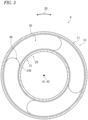
FIG. 2 is a plan view of the rotary connector device shown inFIG. 1 . -
FIG. 3 is a cross-sectional view of the rotary connector device shown inFIG. 1 . -
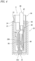
FIG. 4 is a cross-sectional view of the rotary connector device taken along line IV-IV ofFIG. 2 . -
FIG. 5 is a schematic diagram showing the impact of the misalignment between a rotational axis of a rotator shown inFIG. 1 and a steering axis on the coupling portion between the rotator-side connector and the harness connector of the wire harness. -
FIG. 6 is a cross-sectional view showing the impact of the misalignment between the rotational axis of the rotator shown inFIG. 1 and the steering axis on the coupling portion between the rotator-side connector and the harness connector of the wire harness. -
FIG. 7 is a partial top view of the rotary connector device shown inFIG. 1 (with the cable holder omitted). -
FIG. 8 is a cross-sectional view of the rotary connector device taken along line VIII-VIII ofFIG. 9 . -
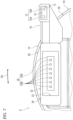
FIG. 9 is a partial top view of the rotary connector device shown inFIG. 1 . - Embodiments will be described below with reference to the drawings. In the drawings, the same reference signs indicate corresponding or identical configurations.
- As shown in
FIG. 1 , an in-vehicle apparatus 1 comprises arotary connector device 6 and awire harness 8. The in-vehicle apparatus 1 further comprises asteering wheel 2. Thewire harness 8 includes aharness connector 8A and acable 8B. For instance, thecable 8B includes a plurality of electric cables. The plurality of electric cables is electrically connected to a plurality of connector terminals of theharness connector 8A. However, thecable 8B may include at least one electric cable. - The
steering wheel 2 is coupled to a vehicle body 4 rotatably about a steering rotational axis A1. Thesteering wheel 2 includes, for example, asteering body 2A, asteering cover 2B, asupport frame 2C, and a firstelectrical device 2D. The vehicle body 4 includes, for example, acolumn cover 4A, asteering column 4B, and a secondelectrical device 4D. - The
steering body 2A is rotatably supported about the steering rotational axis A1 by thesteering column 4B. Thesteering cover 2B and thesupport frame 2C are attached to thesteering body 2A. The firstelectrical device 2D is attached to thesupport frame 2C. Thesteering body 2A, thesteering cover 2B, thesupport frame 2C, and the firstelectrical device 2D are rotatable about the steering rotational axis A1 relative to the vehicle body 4. Thecolumn cover 4A and the secondelectrical device 4D are attached to thesteering column 4B. The firstelectrical device 2D is electrically connected to the secondelectrical device 4D via therotary connector device 6. - The
rotary connector device 6 comprises astator 10 and arotator 20. Therotator 20 is rotatably provided about a rotational axis A2 relative to thestator 10. Thestator 10 is configured to be coupled to the vehicle body 4 (e.g., thesteering column 4B). Therotator 20 is configured to be coupled to the steering wheel 2 (e.g., thesteering body 2A). - As shown in
FIG. 2 , therotator 20 includes arotator body 21 and a rotator-side connector 22. Therotator body 21 is rotatably provided about the rotational axis A2 relative to thestator 10. - As shown in
FIG. 1 , the rotator-side connector 22 protrudes from therotator body 21 along the rotational axis A2. The rotator-side connector 22 is detachably connectable to aharness connector 8A provided at an end of thecable 8B of thewire harness 8. - The
rotator body 21 includes adisc portion 21A, acylindrical portion 21B, and asleeve 21C. Thecylindrical portion 21B extends along the rotational axis A2 from the inner periphery of thedisc portion 21A. Thesleeve 21C is attached to the end of thecylindrical portion 21B. The rotator-side connector 22 extends along the rotational axis A2 from thedisc portion 21A. - The
wire harness 8 is electrically connected to the firstelectrical device 2D. Thecable 8B of thewire harness 8 is flexible. The rotator-side connector 22 is electrically connected to the firstelectrical device 2D via thewire harness 8. The rotator-side connector 22 may also be referred to as afirst connector 22. Thewire harness 8 may also be referred to as afirst wire harness 8. - As shown in
FIG. 2 , the rotator-side connector 22 includes aconnector attachment hole 23. Theconnector attachment hole 23 houses theharness connector 8A in a state where theharness connector 8A is connected to the rotator-side connector 22. The rotator-side connector 22 includes aconnector case 24 including theconnector attachment hole 23. - The rotator-
side connector 22 includes afirst lead block 25. Thefirst lead block 25 is provided in theconnector attachment hole 23. Thefirst lead block 25 includes alead block body 25A and a plurality oflead block terminals 25B. Thelead block body 25A includes an insulating material. The plurality oflead block terminals 25B includes a conductive material. The plurality oflead block terminals 25B is partially provided in thelead block body 25A. In a state where theharness connector 8A is arranged in theconnector attachment hole 23, the plurality oflead block terminals 25B of thefirst lead block 25 are contactable with the plurality of connector terminals of theharness connector 8A. - As shown in
FIG. 1 , thestator 10 includes astator body 11 and a stator-side connector 12. Thestator body 11 is secured to thesteering column 4B of the vehicle body 4. The stator-side connector 12 protrudes from thestator body 11 along the rotational axis A2. The stator-side connector 12 is detachably connectable to aharness connector 9A provided at an end of thecable 9B of thewire harness 9. - The
wire harness 9 is electrically connected to the secondelectrical device 4D. Thecable 9B of thewire harness 9 is flexible. The stator-side connector 12 is electrically connected to the secondelectrical device 4D via thewire harness 9. The stator-side connector 12 may also be referred to as asecond connector 12. Thewire harness 9 may also be referred to as asecond wire harness 9. - The stator-
side connector 12 includes aconnector housing space 13. Theconnector housing space 13 houses theharness connector 9A in a state where theharness connector 9A is connected to the stator-side connector 12. The stator-side connector 12 includes a connector case 14 including theconnector housing space 13. - The stator-
side connector 12 includes asecond lead block 15. Thesecond lead block 15 is provided in theconnector housing space 13. Thesecond lead block 15 includes alead block body 15A and a plurality oflead block terminals 15B. Thelead block body 15A includes an insulating material. The plurality oflead block terminals 15B includes a conductive material. The plurality oflead block terminals 15B is partially provided in thelead block body 15A. In a state where theharness connector 9A is arranged in theconnector housing space 13, the plurality oflead block terminals 15B of thesecond lead block 15 is contactable with the plurality of connector terminals of theharness connector 9A. - As shown in
FIG. 3 , thestator 10 and therotator 20 form, between thestator 10 and therotator 20, acable housing space 50 provided to surround the rotational axis A2. Thecable housing space 50 extends in a circumferential direction D3 and has an annular shape. - The
rotary connector device 6 comprises anelectrical cable 60. Theelectrical cable 60 is arranged in thecable housing space 50. Theelectrical cable 60 electrically connects the rotator-side connector 22 (seeFIG. 2 ) and the stator-side connector 12 (seeFIG. 2 ). Theelectrical cable 60 electrically connects the first lead block 25 (seeFIG. 2 ) to the second lead block 15 (seeFIG. 2 ). Theelectrical cable 60 includes a plurality of conductors. The plurality of conductors of theelectrical cable 60 is connected to the plurality oflead block terminals 25B of thefirst lead block 25, respectively, and is connected to the plurality oflead block terminals 15B of thesecond lead block 15, respectively. Theelectrical cable 60 is flexible and, for example, has a flat shape. Theelectrical cable 60 may also be referred to as a flexibleflat cable 60. - As shown in
FIG. 4 , theharness connector 8A includes aharness connector case 8D and a plurality ofconnector terminals 8E (one of the plurality ofconnector terminals 8E is shown inFIG. 4 ). The plurality ofconnector terminals 8E is arranged in positions corresponding to the plurality oflead block terminals 25B (seeFIG. 2 ). - The
cable 8B includes a plurality ofcables 8F. The plurality ofconnector terminals 8E is electrically connected to the plurality ofcables 8F. The plurality ofconnector terminals 8E is provided in theharness connector case 8D and is attached to theharness connector case 8D. - Each of the plurality of
connector terminals 8E includes abead 8G and adimple 8H. Thelead block terminal 25B of thefirst lead block 25 is sandwiched between thebead 8G and thedimple 8H of theconnector terminals 8E in the state where theharness connector 8A is connected to the rotator-side connector 22. Thus, the plurality oflead block terminals 25B of thefirst lead block 25 is in contact with the plurality ofconnector terminals 8E of theharness connector 8A, respectively. - As shown in
FIG. 1 , it is preferable to attach therotary connector device 6 to the vehicle body 4 such that the rotational axis A2 of therotator 20 aligns with the steering rotational axis A1. - Due to manufacturing errors and/or mounting errors of the parts, however, there may be instances where the
rotary connector device 6 is attached to the vehicle body 4 in a state where the rotational axis A2 of therotator 20 is misaligned from the steering rotational axis A1. Due to the misalignment between the rotational axis A2 of therotator 20 and the steering rotational axis A1, physical load can be placed on the coupling portion between the rotator-side connector 22 and theharness connector 8A during the rotation of thesteering body 2A and therotator 20, which may result in wear at the contact portion between thelead block terminal 25B and theconnector terminal 8E. - Here, using
FIG. 5 , the impact of the misalignment between the rotational axis A2 of therotator 20 and the steering rotational axis A1 on the coupling portion between the rotator-side connector 22 and theharness connector 8A will be explained. The top section ofFIG. 5 shows an example of the movement of therotary connector device 6 and thesteering wheel 2 from the driver's perspective. The middle section ofFIG. 5 illustrates an example of the movement of thesteering wheel 2 relative to therotary connector device 6. The bottom section ofFIG. 5 shows an example of the force acting from thecable 8B on theharness connector 8A connected to the rotator-side connector 22. The center point P2 of the rotator-side connector 22 is set as the reference point P1 in a case where the rotational axis A2 aligns with the steering rotational axis A1. - As shown in
FIG. 5 , in a case where the rotational axis A2 of therotator 20 is misaligned from the steering rotational axis A1, the center point P2 of the rotator-side connector 22 is also misaligned from the reference point P1. When thesteering body 2A and therotator 20 rotate in this state, the center point P2 moves in various directions relative to the reference point P1. As a result, as shown inFIG. 6 , when thesteering body 2A and therotator 20 rotate, forces are transmitted in various directions through thecable 8B to theharness connector 8A connected to the rotator-side connector 22, causing theharness connector 8A to move within theconnector attachment hole 23 of the rotator-side connector 22. Consequently, thelead block terminal 25B of thefirst lead block 25 and theconnector terminal 8E of theharness connector 8A rub against each other, leading to wear of at least one of thelead block terminal 25B and theconnector terminal 8E. - Thus, as shown in
FIG. 2 , therotary connector device 6 comprises aholder attachment portion 70 and acable holder 80. Thecable holder 80 is detachably attached to theholder attachment portion 70. Thecable holder 80 holds thecable 8B in a state where theharness connector 8A is connected to the rotator-side connector 22. - As shown in
FIG. 7 , theholder attachment portion 70 is coupled to therotator 20 and includes aholder attachment hole 71. In the present embodiment, theholder attachment portion 70 is a separate member from therotator 20 and is secured to therotator 20. Theholder attachment portion 70 is a separate member from the rotator-side connector 22 and is secured to the rotator-side connector 22. However, theholder attachment portion 70 may be integrally provided with therotator 20 as a one-piece, unitary member. Theholder attachment portion 70 may be integrally provided with the rotator-side connector 22 as a one-piece, unitary member. - The
holder attachment hole 71 is at least partially provided radially outward relative to therotator 20 when viewed along the rotational axis A2. Theholder attachment hole 71 is at least partially provided radially outward relative to the rotator-side connector 22 when viewed along the rotational axis A2. Theholder attachment hole 71 is at least partially provided radially outward relative to theconnector attachment hole 23 when viewed along the rotational axis A2. - In the present embodiment, the
holder attachment hole 71 is entirely provided radially outward relative to therotator 20 when viewed along the rotational axis A2. Theholder attachment hole 71 is entirely provided radially outward relative to the rotator-side connector 22 when viewed along the rotational axis A2. Theholder attachment hole 71 is entirely provided radially outward relative to theconnector attachment hole 23 when viewed along the rotational axis A2. However, theholder attachment hole 71 may be partially provided radially outward relative to therotator 20 when viewed along the rotational axis A2. Theholder attachment hole 71 may be partially provided radially outward relative to the rotator-side connector 22 when viewed along the rotational axis A2. Theholder attachment hole 71 may be partially provided radially outward relative to theconnector attachment hole 23 when viewed along the rotational axis A2. Theholder attachment hole 71 may be partially provided radially inward of the outline of therotator 20 when viewed along the rotational axis A2. - As shown in
FIG. 8 , thecable holder 80 is detachably attached to theholder attachment hole 71. Theholder attachment hole 71 opens in the axial direction D1 to enable thecable holder 80 to be inserted in and removed from theholder attachment hole 71 in the axial direction D1 defined along the rotational axis A2. As shown inFIG. 4 , theconnector attachment hole 23 opens in the axial direction D1 to enable theharness connector 8A to be inserted in and removed from theholder attachment hole 71 in the axial direction D1. - The
cable holder 80 and theholder attachment portion 70 have an engagement structure. As shown inFIG. 8 , thecable holder 80 includes arecess 81. Theholder attachment portion 70 includes aprotrusion 72 provided in theholder attachment hole 71. Theprotrusion 72 engages with therecess 81 in a state where thecable holder 80 is inserted in theholder attachment hole 71. Theprotrusion 72 is at least partially arranged in therecess 81 in the state where thecable holder 80 is inserted in theholder attachment hole 71. - The
protrusion 72 includes afirst contact surface 72A. Therecess 81 includes asecond contact surface 81A. Thefirst contact surface 72A of theprotrusion 72 is contactable with thesecond contact surface 81A of therecess 81 in the state where thecable holder 80 is inserted in theholder attachment hole 71. Thefirst contact surface 72A and thesecond contact surface 81A are perpendicular to the axial direction D1. - The
cable holder 80 includes arelease portion 82 configured to release engagement between therecess 81 and theprotrusion 72 based on a user operation. Therelease portion 82 is elastically deformable in response to the user operation. Therelease portion 82 is elastically deformable such that the position of therecess 81 is changed relative to theprotrusion 72 in response to the user operation. Pressing therelease portion 82 by the user to elastically deform therelease portion 82 disengages the engagement between therecess 81 and theprotrusion 72, enabling thecable holder 80 to be removed from theholder attachment portion 70. Additionally, when thecable holder 80 is inserted into theholder attachment hole 71, therelease portion 82 is elastically deformed, enabling thecable holder 80 to be inserted in theholder attachment hole 71 to a position in which theprotrusion 72 engages with therecess 81. - As shown in
FIG. 9 , therotary connector device 6 further comprises acoupling member 90 coupling thecable holder 80 to thecable 8B. Thecoupling member 90 includes at least two couplingbands 91 coupling thecable holder 80 to thecable 8B. Thecoupling band 91 may include a zip tie. Thecable holder 80 includes acoupling portion 83. Thecoupling portion 83 is coupled to thecable 8B by thecoupling member 90. Thecoupling portion 83 is coupled to thecable 8B by thecoupling band 91. - The
cable 8B of thewire harness 8 is arranged to curve in a region from theharness connector 8A to thecable holder 80 in the state where theharness connector 8A is connected to the rotator-side connector 22. For instance, as viewed along the rotational axis A2, thecable 8B of thewire harness 8 is arranged to curve in the region from theharness connector 8A to thecable holder 80 in the state where theharness connector 8A is connected to the rotator-side connector 22. However, the direction in which thecable 8B curves is not limited to the illustrated direction. - The
cable 8B of thewire harness 8 includes a curved portion 8B1 and a secured portion 8B2. The curved portion 8B1 is electrically connected to theharness connector 8A and is provided between theharness connector 8A and the secured portion 8B2. The secured portion 8B2 is secured to thecoupling portion 83 of thecable holder 80 by thecoupling member 90. - As shown in
FIG. 9 , theholder attachment portion 70 includes aholder holding portion 73. Theholder holding portion 73 is contactable with thecable holder 80 to hold thecable holder 80 in a state where thecable holder 80 is inserted in theholder attachment hole 71. Theholder holding portion 73 includes holdingportions - The
cable holder 80 includes holdinggrooves portion 73A is provided in the holdinggroove 84A in the state where thecable holder 80 is inserted in theholder attachment hole 71. The holdingportion 73B is provided in the holdinggroove 84B in the state where thecable holder 80 is inserted in theholder attachment hole 71. - As described above, the
rotary connector device 6 comprises thestator 10, therotator 20, theholder attachment portion 70, and thecable holder 80. Therotator 20 includes the rotator-side connector 22 detachably connectable to theharness connector 8A provided at the end of thecable 8B of thewire harness 8. Therotator 20 is rotatably provided about the rotational axis A2 relative to thestator 10. Theholder attachment portion 70 is coupled to therotator 20 and includes theholder attachment hole 71. Thecable holder 80 is detachably attached to theholder attachment hole 71 and holds thecable 8B in the state where theharness connector 8A is connected to the rotator-side connector 22. Thecable holder 80 includes therecess 81. Theholder attachment portion 70 includes theprotrusion 72. Theprotrusion 72 is provided in theholder attachment hole 71 and engages with therecess 81 in the state where thecable holder 80 is inserted in theholder attachment hole 71. - With the
rotary connector device 6, since thecable 8B is held by thecable holder 80 provided to therotator 20 in the state where theharness connector 8A is connected to the rotator-side connector 22, even if the rotational axis A2 of therotator 20 is misaligned from the steering rotational axis A1 of thesteering wheel 2, thecable holder 80 reduces or prevents forces applied from thecable 8B of thewire harness 8 to theharness connector 8A during the rotation of therotator 20 and thesteering wheel 2. Thus, it is possible to reduce or prevent the relative movement between the rotator-side connector 22 and theharness connector 8A during the rotation of therotator 20 and thesteering wheel 2 even if the rotational axis A2 of therotator 20 is misaligned from the steering rotational axis A1. Accordingly, it is possible to reduce or prevent wear of at least one of the rotator-side connector 22 and theharness connector 8A that could be caused by the misalignment between the rotational axis A2 and the steering rotational axis A1. - Since the
protrusion 72 of theholder attachment portion 70 engages with therecess 81 in the state where thecable holder 80 is inserted in theholder attachment hole 71, thecable holder 80 can be attached to or detached from theholder attachment hole 71. Thus, the assembleability and maintainability of thecable holder 80 can be improved. - In the present application, the term "comprise" and its derivatives are open-ended terms used to describe the existence of components and do not exclude the presence of other components not described. This also applies to the terms "have," "include," and their derivatives.
- In the present application, ordinal terms such as "first" and "second" are merely used to identify configurations and do not have other meanings, such as implying a specific order. For example, the existence of a "first element" does not necessarily imply the existence of a "second element," nor does the existence of a "second element" necessarily imply the existence of a "first element."
- Expressions such as "parallel," "perpendicular," and "coincide" in the present disclosure should not be interpreted strictly; rather, they include the meanings of "substantially parallel," "substantially perpendicular," and "substantially coincide," respectively. Similarly, other expressions regarding arrangement should not be interpreted strictly.
- The expression "at least one of A and B" in the present disclosure encompasses, for example, (1) only A, (2) only B, and (3) both A and B. Similarly, the expression "at least one of A, B, and C" encompasses, for example, (1) only A, (2) only B, (3) only C, (4) both A and B, (5) both B and C, (6) both A and C, and (7) all of A, B, and C. The expression "at least one of A and B" in the present disclosure should not be interpreted as "at least one of A and at least one of B."
- Obviously, numerous modifications and variations of the present invention are possible in light of the above teachings. It is therefore to be understood that within the scope of the appended claims, the invention may be practiced otherwise than as specifically described herein.
-
- 1: Vehicle-mounted device
- 2: Steering wheel
- 4: Vehicle body
- 6: Rotary connector device
- 8: Wire harness
- 8A: Harness connector
- 8B: Cable
- 10: Stator
- 20: Rotator
- 21: Rotator body
- 22: Rotator-side connector
- 23: Connector attachment hole
- 24: Connector case
- 25: First lead block
- 50: Cable housing space
- 60: Electric cable
- 70: Holder attachment portion
- 71: Holder attachment hole
- 72: Protrusion
- 73: Holder holding portion
- 80: Cable holder
- 81: Recess
- 82: Release portion
- 83: Connection portion
- 90: Connecting member
- 91: Connection band
- A1: Steering rotational axis
- A2: Rotational axis
- D1: Axial direction
- D3: Circumferential direction
Claims (9)
- A rotary connector device comprising:a stator;a rotator including a rotator-side connector detachably connectable to a harness connector provided at an end of a cable of a wire harness, the rotator being rotatably provided about a rotational axis relative to the stator;a holder attachment portion coupled to the rotator and including a holder attachment hole; anda cable holder detachably attached to the holder attachment hole, the cable holder holding the cable in a state where the harness connector is connected to the rotator-side connector,the holder attachment portion and the cable holder having an engagement structure.
- The rotary connector device according to claim 1, whereinthe cable holder includes a recess, andthe holder attachment portion includes a protrusion provided in the holder attachment hole, the protrusion engaging with the recess in a state where the cable holder is inserted in the holder attachment hole.
- The rotary connector device according to claim 1, wherein
the cable holder includes a release portion configured to release engagement between the recess and the protrusion based on a user operation. - The rotary connector device according to claim 1, wherein
the holder attachment hole is at least partially provided radially outward relative to the rotator when viewed along the rotational axis. - The rotary connector device according to claim 1, wherein
the holder attachment hole opens in an axial direction to enable the cable holder to be inserted in and removed from the holder attachment hole in the axial direction defined along the rotational axis. - The rotary connector device according to claim 5, whereinthe rotator-side connector includes a connector attachment hole, andthe connector attachment hole opens in the axial direction to enable the harness connector to be inserted in and removed from the connector attachment hole in the axial direction.
- The rotary connector device according to any one of claims 1 to 6, further comprising
a coupling member coupling the cable holder to the cable. - The rotary connector device according to claim 7, wherein
the coupling member includes at least two coupling bands coupling the cable holder to the cable. - An in-vehicle apparatus comprising:the rotary connector device according to any one of claims 1 to 6; andthe wire harness including the harness connector and the cable,the cable of the wire harness being arranged to curve in a region from the harness connector to the cable holder in a state where the harness connector is connected to the rotator-side connector.
Applications Claiming Priority (2)
| Application Number | Priority Date | Filing Date | Title |
|---|---|---|---|
| JP2022142382 | 2022-09-07 | ||
| PCT/JP2023/031017 WO2024053462A1 (en) | 2022-09-07 | 2023-08-28 | Rotational connector device and on-board device |
Publications (2)
| Publication Number | Publication Date |
|---|---|
| EP4583328A1 true EP4583328A1 (en) | 2025-07-09 |
| EP4583328A4 EP4583328A4 (en) | 2025-12-10 |
Family
ID=90191193
Family Applications (1)
| Application Number | Title | Priority Date | Filing Date |
|---|---|---|---|
| EP23863001.6A Pending EP4583328A4 (en) | 2022-09-07 | 2023-08-28 | ROTARY CONNECTOR DEVICE AND EMBEDDED DEVICE |
Country Status (6)
| Country | Link |
|---|---|
| US (1) | US20250202179A1 (en) |
| EP (1) | EP4583328A4 (en) |
| JP (1) | JPWO2024053462A1 (en) |
| KR (1) | KR20250065649A (en) |
| CN (1) | CN119790551A (en) |
| WO (1) | WO2024053462A1 (en) |
Family Cites Families (8)
| Publication number | Priority date | Publication date | Assignee | Title |
|---|---|---|---|---|
| JPH0742072U (en) * | 1993-12-28 | 1995-07-21 | 株式会社東海理化電機製作所 | Roll connector |
| US5833476A (en) * | 1995-05-18 | 1998-11-10 | Niles Parts Co., Ltd. | Rotary connector apparatus |
| KR100295231B1 (en) * | 1996-06-28 | 2001-09-17 | 스즈키 다케토시 | Rotary Connector Device |
| JP3552532B2 (en) * | 1998-05-08 | 2004-08-11 | 住友電装株式会社 | Connector with wire retainer |
| JP6229685B2 (en) * | 2015-03-24 | 2017-11-15 | コベルコ建機株式会社 | Construction machine routing structure |
| JP6735344B2 (en) | 2016-05-31 | 2020-08-05 | アルプスアルパイン株式会社 | Rotating connector |
| JP2018045863A (en) * | 2016-09-14 | 2018-03-22 | 株式会社東海理化電機製作所 | Rotating connector |
| WO2019181806A1 (en) * | 2018-03-20 | 2019-09-26 | 株式会社Fomm | Steering curl cord |
-
2023
- 2023-08-28 WO PCT/JP2023/031017 patent/WO2024053462A1/en not_active Ceased
- 2023-08-28 EP EP23863001.6A patent/EP4583328A4/en active Pending
- 2023-08-28 KR KR1020257010918A patent/KR20250065649A/en active Pending
- 2023-08-28 CN CN202380062563.0A patent/CN119790551A/en active Pending
- 2023-08-28 JP JP2024545584A patent/JPWO2024053462A1/ja active Pending
-
2025
- 2025-03-04 US US19/069,243 patent/US20250202179A1/en active Pending
Also Published As
| Publication number | Publication date |
|---|---|
| WO2024053462A1 (en) | 2024-03-14 |
| US20250202179A1 (en) | 2025-06-19 |
| CN119790551A (en) | 2025-04-08 |
| EP4583328A4 (en) | 2025-12-10 |
| KR20250065649A (en) | 2025-05-13 |
| JPWO2024053462A1 (en) | 2024-03-14 |
Similar Documents
| Publication | Publication Date | Title |
|---|---|---|
| EP2086057B1 (en) | Shielded USB connector system | |
| US5139436A (en) | Electrical connecting element for rotating parts | |
| US20250202179A1 (en) | Rotary connector device and in-vehicle apparatus | |
| JP2007202255A (en) | Blower motor radio noise countermeasure structure | |
| EP4178049A1 (en) | Rotational connector device | |
| US20240067109A1 (en) | Rotary connector apparatus and steering apparatus | |
| US20240405480A1 (en) | Connector and connector assembly | |
| EP4462614A1 (en) | Rotary connector device | |
| JP2004314901A (en) | Rotary connector with rotation sensor | |
| EP4044409B1 (en) | Motor brush, motor and washing machine | |
| CN213243720U (en) | Motor interface assembly and motor | |
| US6994557B2 (en) | Electrical connector between two end points | |
| CN114792902A (en) | Electrical connector assembly with endless connection system | |
| US20240113485A1 (en) | Rotary connector device and manufacturing method of rotary connector device | |
| CN216958797U (en) | Novel clock spring and steering wheel and vehicle with same | |
| CN112636120A (en) | Electrical connection device | |
| KR101506742B1 (en) | Vehicle roll connector device | |
| US12218563B2 (en) | Motor | |
| CN115009186B (en) | Steering roller connector assembly and method for assembling steering roller connector assembly | |
| EP2637264B1 (en) | Rotary connector | |
| EP4525222A1 (en) | Flat cable assembly and rotational connector device | |
| JP2024121621A (en) | Wire harness connecting member and rotary connector device | |
| US12160075B2 (en) | Rotary connector device and flat cable assembly for rotary connector device | |
| KR200465066Y1 (en) | Steering roll connector | |
| CN1319222C (en) | Rotary connector |
Legal Events
| Date | Code | Title | Description |
|---|---|---|---|
| STAA | Information on the status of an ep patent application or granted ep patent |
Free format text: STATUS: THE INTERNATIONAL PUBLICATION HAS BEEN MADE |
|
| PUAI | Public reference made under article 153(3) epc to a published international application that has entered the european phase |
Free format text: ORIGINAL CODE: 0009012 |
|
| STAA | Information on the status of an ep patent application or granted ep patent |
Free format text: STATUS: REQUEST FOR EXAMINATION WAS MADE |
|
| 17P | Request for examination filed |
Effective date: 20250331 |
|
| AK | Designated contracting states |
Kind code of ref document: A1 Designated state(s): AL AT BE BG CH CY CZ DE DK EE ES FI FR GB GR HR HU IE IS IT LI LT LU LV MC ME MK MT NL NO PL PT RO RS SE SI SK SM TR |
|
| RAP3 | Party data changed (applicant data changed or rights of an application transferred) |
Owner name: FURUKAWA ELECTRIC CO., LTD. Owner name: FURUKAWA AUTOMOTIVE SYSTEMS INC. Owner name: HONDA MOTOR CO., LTD. |
|
| REG | Reference to a national code |
Ref country code: DE Ref legal event code: R079 Free format text: PREVIOUS MAIN CLASS: H01R0035040000 Ipc: B60R0016027000 |
|
| A4 | Supplementary search report drawn up and despatched |
Effective date: 20251111 |
|
| RIC1 | Information provided on ipc code assigned before grant |
Ipc: B60R 16/027 20060101AFI20251105BHEP Ipc: B60R 16/02 20060101ALI20251105BHEP Ipc: H01R 35/04 20060101ALI20251105BHEP Ipc: H01R 35/02 20060101ALI20251105BHEP Ipc: H01R 13/627 20060101ALN20251105BHEP Ipc: H01R 13/58 20060101ALN20251105BHEP |
|
| DAV | Request for validation of the european patent (deleted) | ||
| DAX | Request for extension of the european patent (deleted) |