JP3552532B2 - Connector with wire retainer - Google Patents
Connector with wire retainer Download PDFInfo
- Publication number
- JP3552532B2 JP3552532B2 JP12632598A JP12632598A JP3552532B2 JP 3552532 B2 JP3552532 B2 JP 3552532B2 JP 12632598 A JP12632598 A JP 12632598A JP 12632598 A JP12632598 A JP 12632598A JP 3552532 B2 JP3552532 B2 JP 3552532B2
- Authority
- JP
- Japan
- Prior art keywords
- electric wire
- upright wall
- wire holder
- connector
- connector housing
- Prior art date
- Legal status (The legal status is an assumption and is not a legal conclusion. Google has not performed a legal analysis and makes no representation as to the accuracy of the status listed.)
- Expired - Fee Related
Links
Images


Description
【0001】
【発明の属する技術分野】
本発明は、電線保持具を備えたコネクタに関するものである。
【0002】
【従来の技術】
従来より、コネクタハウジングの背面から電線の引き出しがなされているものでは、電線に引っ張り力が作用すると、各電線に接続された端子金具においてコネクタハウジング内で係止されている部分(ランス)に直接、引っ張り力が及んでしまう。そのため、従来ではコネクタハウジングの背面にカバーを取り付け、電線を一旦、屈曲させた後に後方へ引き出すようにしたものが知られている。例えば、図13および図14に示されるような特開平9−161883号公報のものを挙げることができる。
図13及び図14に示すカバー100は、その両側面にコネクタハウジング101の突起102に係止される係止腕103が設けられ、カバー100の装着がなされるときに、カバー100の底面とコネクタハウジング101の下面との間に電線Wを噛み込ませ、電線WをU字状に折り返すことができるようにしている。
【0003】
【発明が解決しようとする課題】
しかしながら、上記のように電線Wをカバー100とコネクタハウジング101との間で噛み込ませつつ屈曲させる方式では、カバー100の装着がし辛く、特に電線径が大きいものでは装着に際して大きな力が必要となっていた。また、カバー100の両側にロック手段(係止腕)を配しているため、その分、コネクタ全体としての幅寸法が増し、設置スペースが幅方向に制約を受ける場合に不利となる、という問題点もあった。
本発明の目的は、組み付け作業性に優れる電線保持具を備えたコネクタを提起要することである。
【0004】
【課題を解決するための手段】
上記の目的を達成するための請求項1の発明は、コネクタハウジングの背面から引き出された電線を、前記背面に沿って屈曲させた状態に強制する電線保持具を備えたコネクタであって、前記電線保持具は、前記電線を結束させて保持する保持手段と、前記コネクタハウジングの背面に解離可能に係止して電線引っ張り力に抗する係止手段とを備え、前記コネクタハウジングの背面にはこの背面と面一な起立壁が立設されるとともに、前記係止手段は、前記起立壁に係止する一方、この起立壁の内面に前記係止手段が当接することで、前記電線に対する引っ張り力に抗する構成とされているところに特徴を有する。
【0005】
また請求項2の発明は、請求項1記載のものにおいて、前記起立壁にはその端縁から差込み溝が切り込み形成され、一方、前記係止手段は前記差込み溝に対し入り口側から差し込み可能な幅狭部が形成され、かつこの幅狭部には前記差込み溝より幅広に形成され前記起立壁の内面に当接することで、前記電線に対する引っ張り力を受承する受圧面が連続しているところに特徴を有する。
【0006】
さらに請求項3の発明は、前記起立壁には差し込み孔が貫通して形成される一方、電線保持具には、前記差し込み孔へ差し込み可能な軸部とこの軸部に張り出し状に設けられかつ縮径変形することで前記差し込み孔を貫通可能であり、貫通孔を通過した後は拡径して前記起立壁の内面に当接することで前記電線の引っ張り力を受承する鍔片が形成されているところに特徴を有する。
【0007】
さらにまた請求項4の発明は、請求項2記載のものにおいて、前記差込み溝の入り口部分には、幅狭部の差込みは許容するが幅狭部の通過後には幅狭部の抜けを規制可能なスロート部が形成されていることを特徴とするものである。
【0008】
【作用】
請求項1の発明によれば、コネクタハウジングから引き出された電線を保持手段によって結束して保持させた後、係止手段にてコネクタハウジングの背面の起立壁に係止させる。これにより、電線はコネクタハウジングの背面に沿った状態で取り付けられる。したがって、電線に対して後方への引っ張り力が作用しても、係止手段とコネクタハウジングの背面の起立壁との係止部分に引っ張り力が作用するだけで、電線に接続された端子金具側にその影響が及ぶことはない。
このように、請求項1では電線を保持手段にて保持した後、単にコネクタハウジングの背面の起立壁へ電線保持具の取付けを行うだけでよいため、つまり、電線保持具は従来のようにハウジングとの間で電線を噛み込んで装着されるものでないため、取付けに大きな力を必要としない。
【0009】
請求項2の発明では、電線を保持した状態にある電線保持具のコネクタハウジングへの取り付けは、幅狭部を差込み溝の開口端より差し込むことによって行われる。そして、電線に対し引っ張り力が作用したときには、受圧面が起立壁の内側面に面当りしてこれに抗するため、引っ張り力を確実に受承することができる。
【0010】
請求項3の発明によれば、電線を保持した状態にある電線保持具をコネクタハウジングへ取り付ける場合には、鍔片を差し込み孔へ押し嵌める。このとき、鍔片は縮径変形することで差し込み孔を通過し、通過後には拡径して抜け止めがなされる。これにより、電線に対して引っ張り力が作用したときには、鍔片が起立壁の内面に当接してこれに抗する。
【0011】
請求項4の発明によれば、電線保持具をコネクタハウジングに取り付けるにあたり、幅狭部を差込み溝に押し込むと、幅狭部はスロート部を拡開させつつ差込み溝の奥部へ入り込む。すると、スロート部は復帰して幅狭部の戻りを規制するため、電線保持具の抜けが自動的に防止される。
【0012】
【発明の実施の形態】
−第1実施形態−
図1〜図6は本発明の第1実施形態を示すものである。図中、1は合成樹脂製のコネクタハウジングであり、内部には複数のキャビティ2が前後方向に貫通して形成されている。各キャビティ2の内部には電線Wの先端に接続された端子金具と係合して抜け止めを行う図示しないランスがそれぞれ形成されている。また、コネクタハウジング1の上面には、このコネクタハウジング1に嵌合可能な相手側コネクタハウジングとのロックを行うためのロックアーム3が撓み変形可能に設けられている。
【0013】
また、コネクタハウジング1の上面の後縁には、その全幅に亘って起立壁4が立設されている。この実施の形態では、起立壁4の強度確保等の関係から、コネクタハウジング1の両側縁にかけても延びており、全体として平面コの字状をなして形成されている。さらに、起立壁4の中央にはその上縁からコネクタハウジング1の上面に至る深さをもって差込み溝5が縦向きに形成されている。差込み溝5の入り口側には一対の突片6が間隔を狭めて向き合っており、これらの間は拡開方向の撓み変形可能な幅狭のスロート部7となっている。両突片6の開口側は電線保持具H1の差込みの際の誘い込みを行うために、外向きに拡開するテーパー状をなしている。また、両突片6の下縁はスロート部7の向きと直交する方向(水平方向)に形成され、電線保持具H1の幅狭部8と係合する係止面9となっている。
【0014】
次に、電線保持具H1について説明すると(主として図6参照)、電線保持具H1は一対の保持板10A,10Bを有し、その間の中央を幅狭部8で連結している。一方の保持板10Aの外面には、電線Wを結束するためのクランプ11が設けられている。この実施形態のクランプ11は可撓性を有する一対のバンド片12A,12Bを備え、一方のバンド片12Aの片面には長さ方向に沿って鋸歯状に多数の係止縁13が形成され、他方のバンド片12Bの先端には方形枠状の連結具14が形成されている。連結具14は一方のバンド片12Aを挿通可能であるとともに、その開口縁には任意の係止縁13を解離可能に係止するフック爪15が撓み変形可能に形成されている。
【0015】
また、両保持板10A,10Bを連結する幅狭部8は両保持板10A,10Bの高さよりも低めに形成されかつその幅は前記スロート部7より幅広に設定されており、電線保持具H1全体の押し込み力によって両突片6間を、つまりスロート部7を拡開させながら通過し、スロート部7を通過後に突片6が復帰することに伴って、その上面が両係止面9と係止して電線保持具H1全体の抜け止めがなされるようになっている。こうして、幅狭部を差込み溝へ差し込んだときには、電線保持具Hは両保持板10A,10B間で起立壁4を挟み込んだ状態でコネクタハウジング1に取り付けられる。そして、保持板10A,10Bのうち起立壁4の内側に位置するものの内面は、起立壁4の内面に当接することで電線Wの引っ張り力に抗する受圧面16となる。
なお、保持板10A,10Bは起立壁4の内側にはまり込むことができる程度の幅寸法に形成され、その高さは電線保持具Hをコネクタハウジング1に取り付けたときにはその上縁が起立壁4の上縁と面一かそれより低位となるように形成されている。
【0016】
次に、上記のように構成された第1実施形態の作用効果を説明すると、コネクタハウジング1の各キャビティ2に対して電線Wに接続された端子金具を挿入する。これによって、各端子金具はキャビティ2内の図示しないランスと弾性的に係止して抜け止めがなされる。こうして、コネクタハウジング1の背面から引き出された各電線Wを電線保持具H1のクランプ11によって結束する。すなわち、各電線Wを両バンド片12A,12Bにて束ね、係止縁13が形成されている側のバンド片12Aを連結具13に通し、各電線Wが緊締されるまでバンド片12A,12Bを縛り込んだ状態で係止縁13とフック爪15とを係止させる。これにより、各電線Wは結束状態で電線保持具Hに保持される。
【0017】
次に、電線保持具H1の幅狭部8を差込み溝5の開口部に適合させてそのまま押し込んでやると、幅狭部8は両突片6を押し広げることでスロート部7を拡開させ、スロート部7を通過後には復帰した両突片6の係止面9によって抜け止めがなされる。かくして、電線保持具H1がコネクタハウジング1に取り付けられる結果、各電線Wがコネクタハウジング1の背面に沿って屈曲状態で保持される。その後、各電線Wはコネクタハウジング1の後方へ延出されるのであるが、電線Wに引っ張り力が作用しても、この引っ張り力は電線保持具H1に作用し、キャビティ2内の図示しないランス部分には作用しない。より詳しくは、電線保持具H1に作用した引っ張り力は受圧面16が起立壁4の内面に当接することで受承される。つまり、受圧面4全体でこの引っ張り力に抗するため、コネクタハウジング1側の不用意な変形を生じさせず、引っ張り力を確実に受け止めることができる。
【0018】
また、この実施形態では両保持板10A,10Bは起立壁4より幅狭に形成されるから、電線保持具Hがコネクタハウジング1の幅方向に突出することがなく、したがって従来に比較してコネクタ全体として幅方向に大型化することが回避でき、設置スペースに制約が有る場合に有効である。
さらに、従来のようにカバーを使って電線Wの屈曲を行うようなものでは、電線Wを噛み込む関係で装着時に大きな力を必要としていたが、この実施形態では、電線保持具H1の取付けによって電線Wの屈曲を行い、かつ電線保持具H1の取付けは単に差込み溝5への差込みによってのみ行われるため、取付けに際して必要な力は小さくてすむ。
【0019】
−第2実施形態−
図7は本発明の第2実施形態に係る電線保持具H2を示すものである。この実施形態では、両保持板10C,10Dを円板状に形成したものであり、幅狭部8は両保持板10C,10Dの中心同士を連結した構造となっている。このように保持板10C,10Dを円板状に形成することで、コネクタハウジング1の差込み溝5に対する取付け方向に制約がなくなり、作業性に優れたものとなる。
他の構成は、第1実施形態と同様であり、同様の作用効果を発揮する。
【0020】
−第3実施形態−
図8は本発明の第3実施形態に係る電線保持具H3を示すものである。前記した両実施形態ではいずれも保持板が一対、備えられたものを示したが、この実施形態では、受圧面16を有する側の保持板10E(起立壁の内側に当接する側の保持板)のみ設けられている。また、クランプ11は幅狭部8の前面中央部に配されている。
このような構造であれば、第1,第2の実施形態の電線保持具よりも構造がより簡素化される利点がある。
他の構成は第1,第2の実施形態と同様であり、同様の作用効果を発揮することができる。
【0021】
−第4実施形態−
図9は本発明の第4実施形態に係るコネクタハウジング1Aを示すものであり、起立壁4に設けられる差込み溝5を横向きに形成したものである。この構成では、電線Wが上方へ引っ張られたときに、差込み溝5の開口方向がこの引っ張り方向と直交する方向であることから、電線保持具が外れ難くなるという効果が得られる。
他の構成は前記した各実施形態と同様であり、同様の作用効果を発揮することができる。
【0022】
−第5実施形態−
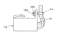
図10〜図12は本発明の第5実施形態を示すものである。この実施形態におけるコネクタハウジング1Bは、起立壁4が上面の後縁のみに立設されており、その中央部には円形の差し込み孔17が貫通している。一方、電線保持具H4は前記した各実施例のバンド片と同様の構成に係るものが使用されるとともに、このバンド片の中央部にクリップ18が備えられている。クリップは、差し込み孔へ差し込み可能な軸部18Aとこの軸部18Aの先端側に拡開および窄み変形可能な一対の鍔片18Bを備えた構造となっている。鍔片18Bは、窄み変形して差し込み孔17を通過可能であるが、通過後には拡開状態に復帰して起立壁の内面側に突っ張る。こうすることで、電線Wに対する引っ張り力に抗することができる。
このような構成によっても、前記した各実施形態と同様の作用効果を発揮することができる。
【0023】
なお、本発明は種々の変更が可能であり、次のような変形例も本発明の技術的範囲に含まれる。
▲1▼いずれの実施形態においても、電線Wに対するクランプは電線保持具に一体に形成される必要はなく、別体のものであってもよい。また、クランプの方式はバンドによって締め上げる方式でなくともよく、単にリング状をなしたものに電線Wを通すだけの構造のものであってもよい。この場合、電線Wを一括して挿通するものの他、多数の通し孔をもって個別に挿通するようなものでもよい。
▲2▼いずれの実施形態もコネクタハウジング側に差込み溝あるいは差し込み孔を形成したが、これらを電線保持具側に配し、起立壁側に幅狭部あるいはクリップを配してもよい。
【図面の簡単な説明】
【図1】第1実施形態において電線保持具を取り付ける前の状態を示す斜視図
【図2】同じく取り付け後の状態を示す斜視図
【図3】幅狭部が差込み溝内で係止されている状態の要部を示す断面図
【図4】同じく側方から見た断面図
【図5】電線の結束部分を示す断面図
【図6】電線保持具を裏側から見た斜視図
【図7】第2実施形態に係る電線保持具を裏側から見た斜視図
【図8】第3実施形態に係る電線保持具を裏側から見た斜視図
【図9】第4実施形態に係るコネクタハウジングの背面図
【図10】第5実施形態に係るコネクタの斜視図
【図11】同じく電線保持具の取付け前の状態を示す側面図
【図12】同じく取付け後の状態を示す側面図
【図13】従来のコネクタを示す分解斜視図
【図14】同じく組み付け状態の側面図
【符号の説明】
1…コネクタハウジング
4…起立壁
5…差込み溝
7…スロット部
8…幅狭部(係止手段)
10A〜10E…保持板(係止手段)
11…クランプ(保持手段)
16…受圧面
17…差込み孔[0001]
TECHNICAL FIELD OF THE INVENTION
The present invention relates to a connector provided with a wire holder.
[0002]
[Prior art]
Conventionally, when a wire is pulled out from the rear surface of a connector housing, when a pulling force acts on the wire, a portion (lance) locked in the connector housing in a terminal fitting connected to each wire is directly connected to the wire. , The pulling force will reach. Therefore, conventionally, a cover is attached to the rear surface of the connector housing, and the wire is once bent and then pulled backward. For example, Japanese Unexamined Patent Publication No. 9-161883 shown in FIGS. 13 and 14 can be used.
The
[0003]
[Problems to be solved by the invention]
However, in the method in which the electric wire W is bent while being bitten between the
SUMMARY OF THE INVENTION It is an object of the present invention to provide a connector provided with an electric wire holder which is excellent in assembling workability.
[0004]
[Means for Solving the Problems]
The invention according to
[0005]
The invention of
[0006]
Furthermore the invention of
[0007]
According to a fourth aspect of the present invention, in the second aspect, the narrow portion can be inserted at the entrance of the insertion groove, but the narrow portion can be prevented from coming off after passing through the narrow portion. A characteristic throat portion is formed.
[0008]
[Action]
According to the first aspect of the present invention, after the wires drawn out of the connector housing are bound and held by the holding means, the wires are locked to the upright wall on the back surface of the connector housing by the locking means. Thus, the electric wires are attached along the back surface of the connector housing. Therefore, even if a pulling force acts on the wire backward, only the pulling force acts on the locking portion between the locking means and the upright wall on the rear surface of the connector housing. Is not affected.
As described above, in the first aspect, after the electric wire is held by the holding means, the electric wire holder may be simply attached to the upright wall on the back surface of the connector housing. Since the electric wire is not mounted by biting the electric wire between them, a large force is not required for mounting.
[0009]
According to the second aspect of the invention, the electric wire holder holding the electric wire is attached to the connector housing by inserting the narrow portion from the opening end of the insertion groove. Then, when a tensile force acts on the electric wire, the pressure receiving surface comes into contact with the inner surface of the upright wall and resists it, so that the tensile force can be reliably received.
[0010]
According to the third aspect of the present invention, when attaching the electric wire holder holding the electric wire to the connector housing, the flange piece is pressed into the insertion hole. At this time, the flange piece passes through the insertion hole by being reduced in diameter, and after passing through, the diameter is increased to prevent falling off. Thereby, when a pulling force acts on the electric wire, the flange piece abuts against the inner surface of the upright wall and resists it.
[0011]
According to the fourth aspect of the present invention, when attaching the wire holder to the connector housing, when the narrow portion is pushed into the insertion groove, the narrow portion enters the deep portion of the insertion groove while expanding the throat portion. Then, the throat portion returns to regulate the return of the narrow portion, so that the wire holder is automatically prevented from coming off.
[0012]
BEST MODE FOR CARRYING OUT THE INVENTION
-1st Embodiment-
1 to 6 show a first embodiment of the present invention. In the figure,
[0013]
An
[0014]
Next, the electric wire holder H1 will be described (refer mainly to FIG. 6). The electric wire holder H1 has a pair of holding
[0015]
Further, the
The holding
[0016]
Next, the operation and effect of the first embodiment configured as described above will be described. A terminal fitting connected to the electric wire W is inserted into each
[0017]
Next, the
[0018]
Further, in this embodiment, since both holding
Further, in the conventional case where the electric wire W is bent by using the cover, a large force is required at the time of mounting because the electric wire W is bitten, but in this embodiment, the electric wire holder H1 is attached by attaching the electric wire holder H1. Since the electric wire W is bent and the electric wire holder H1 is attached simply by inserting the electric wire holder H1 into the
[0019]
-2nd Embodiment-
FIG. 7 shows an electric wire holder H2 according to a second embodiment of the present invention. In this embodiment, both holding
Other configurations are the same as those of the first embodiment, and exhibit the same functions and effects.
[0020]
-Third embodiment-
FIG. 8 shows an electric wire holder H3 according to a third embodiment of the present invention. In each of the above embodiments, a pair of holding plates is provided, but in this embodiment, the holding
With such a structure, there is an advantage that the structure is simplified more than the electric wire holders of the first and second embodiments.
Other configurations are the same as those of the first and second embodiments, and the same functions and effects can be exerted.
[0021]
-Fourth embodiment-
FIG. 9 shows a connector housing 1A according to a fourth embodiment of the present invention, in which an
Other configurations are the same as those of the above-described embodiments, and the same operation and effect can be exhibited.
[0022]
-Fifth embodiment-
10 to 12 show a fifth embodiment of the present invention. In the connector housing 1B in this embodiment, the
With such a configuration, the same operation and effect as those of the above-described embodiments can be exhibited.
[0023]
The present invention can be variously modified, and the following modifications are also included in the technical scope of the present invention.
(1) In any of the embodiments, the clamp for the electric wire W does not need to be formed integrally with the electric wire holder, and may be a separate member. Further, the method of clamping need not be a method of tightening with a band, but may be a structure of simply passing the electric wire W through a ring-shaped member. In this case, the electric wires W may be inserted all at once, or may be individually inserted with a large number of through holes.
{Circle around (2)} Although the insertion groove or the insertion hole is formed on the connector housing side in each of the embodiments, these may be disposed on the electric wire holder side, and a narrow portion or a clip may be disposed on the upright wall side.
[Brief description of the drawings]
FIG. 1 is a perspective view showing a state before attaching an electric wire holder in the first embodiment; FIG. 2 is a perspective view showing a state after attaching the electric wire holder; FIG. 3 is a perspective view showing a state where a narrow portion is locked in an insertion groove; FIG. 4 is a cross-sectional view of the same part viewed from the side. FIG. 5 is a cross-sectional view of a binding part of the electric wire. FIG. 6 is a perspective view of the electric wire holder viewed from the back. FIG. 8 is a perspective view of the electric wire holder according to the second embodiment as viewed from the back side. FIG. 8 is a perspective view of the electric wire holder according to the third embodiment as viewed from the back side. FIG. 9 is a perspective view of the connector housing according to the fourth embodiment. FIG. 10 is a perspective view of the connector according to the fifth embodiment. FIG. 11 is a side view showing a state before the electric wire holder is attached. FIG. 12 is a side view showing a state after the electric wire holder is attached. FIG. 14 is an exploded perspective view showing a conventional connector. FIG. 14 is a side view of the same assembled state. Description]
DESCRIPTION OF
10A to 10E: holding plate (locking means)
11 Clamp (holding means)
16 ...
Claims (4)
前記電線保持具は、前記電線を結束させて保持する保持手段と、前記コネクタハウジングの背面に解離可能に係止して電線引っ張り力に抗する係止手段とを備え、
前記コネクタハウジングの背面にはこの背面と面一な起立壁が立設されるとともに、前記係止手段は、前記起立壁に係止する一方、この起立壁の内面に前記係止手段が当接することで、前記電線引っ張り力に抗することを特徴とする電線保持具を備えたコネクタ。 A connector provided with a wire retainer for forcing an electric wire drawn from a back surface of the connector housing to be bent along the back surface,
The electric wire holder includes a holding unit that binds and holds the electric wire, and an engaging unit that releasably locks to the back surface of the connector housing and resists a wire pulling force ,
An upright wall flush with the back surface is provided upright on the back surface of the connector housing, and the locking means is locked on the upright wall, while the locking means abuts on the inner surface of the upright wall. A connector provided with an electric wire holder characterized by resisting the electric wire pulling force.
Priority Applications (1)
| Application Number | Priority Date | Filing Date | Title |
|---|---|---|---|
| JP12632598A JP3552532B2 (en) | 1998-05-08 | 1998-05-08 | Connector with wire retainer |
Applications Claiming Priority (1)
| Application Number | Priority Date | Filing Date | Title |
|---|---|---|---|
| JP12632598A JP3552532B2 (en) | 1998-05-08 | 1998-05-08 | Connector with wire retainer |
Publications (2)
| Publication Number | Publication Date |
|---|---|
| JPH11329574A JPH11329574A (en) | 1999-11-30 |
| JP3552532B2 true JP3552532B2 (en) | 2004-08-11 |
Family
ID=14932401
Family Applications (1)
| Application Number | Title | Priority Date | Filing Date |
|---|---|---|---|
| JP12632598A Expired - Fee Related JP3552532B2 (en) | 1998-05-08 | 1998-05-08 | Connector with wire retainer |
Country Status (1)
| Country | Link |
|---|---|
| JP (1) | JP3552532B2 (en) |
Families Citing this family (8)
| Publication number | Priority date | Publication date | Assignee | Title |
|---|---|---|---|---|
| JP2001326027A (en) | 2000-05-15 | 2001-11-22 | Nec Gumma Ltd | Stopper device of usb connector |
| KR200445865Y1 (en) | 2008-01-24 | 2009-09-08 | 경신공업 주식회사 | Wire harness fixing device |
| JP5646974B2 (en) * | 2010-12-02 | 2014-12-24 | 日本圧着端子製造株式会社 | Electrical connector |
| KR101701665B1 (en) * | 2013-03-29 | 2017-02-01 | 미쓰비시덴키 가부시키가이샤 | Sequencer terminal block, sequencer and sequencer unit |
| JP6286189B2 (en) * | 2013-11-21 | 2018-02-28 | 矢崎総業株式会社 | Connector unit and wiring structure |
| CN106151684A (en) * | 2015-04-16 | 2016-11-23 | 鸿富锦精密工业(武汉)有限公司 | Data wire fixed mechanism |
| CN104901143B (en) * | 2015-06-09 | 2016-09-14 | 国网山东济南市历城区供电公司 | Control cable windings device |
| WO2024053462A1 (en) * | 2022-09-07 | 2024-03-14 | 古河電気工業株式会社 | Rotational connector device and on-board device |
-
1998
- 1998-05-08 JP JP12632598A patent/JP3552532B2/en not_active Expired - Fee Related
Also Published As
| Publication number | Publication date |
|---|---|
| JPH11329574A (en) | 1999-11-30 |
Similar Documents
| Publication | Publication Date | Title |
|---|---|---|
| US5725395A (en) | Universal serial bus connector | |
| JP4689986B2 (en) | Band clamp | |
| TWI251962B (en) | Electric connector with cable holding mechanism | |
| US6217358B1 (en) | Connector coupling structure | |
| JPH0973948A (en) | Water-proof crimp contact type connector | |
| JP3552532B2 (en) | Connector with wire retainer | |
| CN218563547U (en) | Screen window section bar and screen window | |
| JP3254368B2 (en) | Clip for fixing resin molded parts | |
| JP3247073B2 (en) | Double locking member for connector | |
| JP3589197B2 (en) | connector | |
| JP3287522B2 (en) | Mounting structure of housing to container wall | |
| JP2574800Y2 (en) | Joint connector | |
| JP4685320B2 (en) | Coaxial cable connector and electronic device storage box | |
| JP3074436B2 (en) | Connector clip | |
| JP2002027642A (en) | Clip for fixing flat harness | |
| JP3126906B2 (en) | Structure and method for locking terminal fitting to connector housing | |
| KR100955646B1 (en) | Terminal connector with rear-holder function | |
| JP5703011B2 (en) | Wire harness ground connection structure | |
| JPH0237218Y2 (en) | ||
| US6152789A (en) | Battery terminal contactor | |
| JP2006049199A (en) | Wire harness | |
| JPH11113143A (en) | Binding band | |
| JP3394178B2 (en) | Wire binding structure for electrical junction box | |
| JP3882006B2 (en) | Long body holder | |
| JPH0422089Y2 (en) |
Legal Events
| Date | Code | Title | Description |
|---|---|---|---|
| A977 | Report on retrieval |
Free format text: JAPANESE INTERMEDIATE CODE: A971007 Effective date: 20040113 |
|
| A131 | Notification of reasons for refusal |
Free format text: JAPANESE INTERMEDIATE CODE: A131 Effective date: 20040127 |
|
| A521 | Written amendment |
Free format text: JAPANESE INTERMEDIATE CODE: A523 Effective date: 20040311 |
|
| TRDD | Decision of grant or rejection written | ||
| A01 | Written decision to grant a patent or to grant a registration (utility model) |
Free format text: JAPANESE INTERMEDIATE CODE: A01 Effective date: 20040413 |
|
| A61 | First payment of annual fees (during grant procedure) |
Free format text: JAPANESE INTERMEDIATE CODE: A61 Effective date: 20040426 |
|
| R150 | Certificate of patent or registration of utility model |
Free format text: JAPANESE INTERMEDIATE CODE: R150 |
|
| FPAY | Renewal fee payment (event date is renewal date of database) |
Free format text: PAYMENT UNTIL: 20080514 Year of fee payment: 4 |
|
| FPAY | Renewal fee payment (event date is renewal date of database) |
Free format text: PAYMENT UNTIL: 20090514 Year of fee payment: 5 |
|
| FPAY | Renewal fee payment (event date is renewal date of database) |
Free format text: PAYMENT UNTIL: 20090514 Year of fee payment: 5 |
|
| FPAY | Renewal fee payment (event date is renewal date of database) |
Free format text: PAYMENT UNTIL: 20100514 Year of fee payment: 6 |
|
| FPAY | Renewal fee payment (event date is renewal date of database) |
Free format text: PAYMENT UNTIL: 20100514 Year of fee payment: 6 |
|
| FPAY | Renewal fee payment (event date is renewal date of database) |
Free format text: PAYMENT UNTIL: 20110514 Year of fee payment: 7 |
|
| LAPS | Cancellation because of no payment of annual fees |