EP4583326A1 - Electrical connection module and connector - Google Patents
Electrical connection module and connector Download PDFInfo
- Publication number
- EP4583326A1 EP4583326A1 EP24222894.8A EP24222894A EP4583326A1 EP 4583326 A1 EP4583326 A1 EP 4583326A1 EP 24222894 A EP24222894 A EP 24222894A EP 4583326 A1 EP4583326 A1 EP 4583326A1
- Authority
- EP
- European Patent Office
- Prior art keywords
- terminal
- mating
- inner housing
- cable
- pair
- Prior art date
- Legal status (The legal status is an assumption and is not a legal conclusion. Google has not performed a legal analysis and makes no representation as to the accuracy of the status listed.)
- Pending
Links
Images





Classifications
-
- H—ELECTRICITY
- H01—ELECTRIC ELEMENTS
- H01R—ELECTRICALLY-CONDUCTIVE CONNECTIONS; STRUCTURAL ASSOCIATIONS OF A PLURALITY OF MUTUALLY-INSULATED ELECTRICAL CONNECTING ELEMENTS; COUPLING DEVICES; CURRENT COLLECTORS
- H01R24/00—Two-part coupling devices, or either of their cooperating parts, characterised by their overall structure
- H01R24/76—Two-part coupling devices, or either of their cooperating parts, characterised by their overall structure with sockets, clips or analogous contacts and secured to apparatus or structure, e.g. to a wall
-
- H—ELECTRICITY
- H01—ELECTRIC ELEMENTS
- H01R—ELECTRICALLY-CONDUCTIVE CONNECTIONS; STRUCTURAL ASSOCIATIONS OF A PLURALITY OF MUTUALLY-INSULATED ELECTRICAL CONNECTING ELEMENTS; COUPLING DEVICES; CURRENT COLLECTORS
- H01R13/00—Details of coupling devices of the kinds covered by groups H01R12/70 or H01R24/00 - H01R33/00
- H01R13/40—Securing contact members in or to a base or case; Insulating of contact members
-
- H—ELECTRICITY
- H01—ELECTRIC ELEMENTS
- H01R—ELECTRICALLY-CONDUCTIVE CONNECTIONS; STRUCTURAL ASSOCIATIONS OF A PLURALITY OF MUTUALLY-INSULATED ELECTRICAL CONNECTING ELEMENTS; COUPLING DEVICES; CURRENT COLLECTORS
- H01R13/00—Details of coupling devices of the kinds covered by groups H01R12/70 or H01R24/00 - H01R33/00
- H01R13/02—Contact members
-
- H—ELECTRICITY
- H01—ELECTRIC ELEMENTS
- H01R—ELECTRICALLY-CONDUCTIVE CONNECTIONS; STRUCTURAL ASSOCIATIONS OF A PLURALITY OF MUTUALLY-INSULATED ELECTRICAL CONNECTING ELEMENTS; COUPLING DEVICES; CURRENT COLLECTORS
- H01R13/00—Details of coupling devices of the kinds covered by groups H01R12/70 or H01R24/00 - H01R33/00
- H01R13/46—Bases; Cases
- H01R13/502—Bases; Cases composed of different pieces
-
- H—ELECTRICITY
- H01—ELECTRIC ELEMENTS
- H01R—ELECTRICALLY-CONDUCTIVE CONNECTIONS; STRUCTURAL ASSOCIATIONS OF A PLURALITY OF MUTUALLY-INSULATED ELECTRICAL CONNECTING ELEMENTS; COUPLING DEVICES; CURRENT COLLECTORS
- H01R13/00—Details of coupling devices of the kinds covered by groups H01R12/70 or H01R24/00 - H01R33/00
- H01R13/46—Bases; Cases
- H01R13/516—Means for holding or embracing insulating body, e.g. casing, hoods
-
- H—ELECTRICITY
- H01—ELECTRIC ELEMENTS
- H01R—ELECTRICALLY-CONDUCTIVE CONNECTIONS; STRUCTURAL ASSOCIATIONS OF A PLURALITY OF MUTUALLY-INSULATED ELECTRICAL CONNECTING ELEMENTS; COUPLING DEVICES; CURRENT COLLECTORS
- H01R13/00—Details of coupling devices of the kinds covered by groups H01R12/70 or H01R24/00 - H01R33/00
- H01R13/46—Bases; Cases
- H01R13/52—Dustproof, splashproof, drip-proof, waterproof, or flameproof cases
- H01R13/5219—Sealing means between coupling parts, e.g. interfacial seal
-
- H—ELECTRICITY
- H01—ELECTRIC ELEMENTS
- H01R—ELECTRICALLY-CONDUCTIVE CONNECTIONS; STRUCTURAL ASSOCIATIONS OF A PLURALITY OF MUTUALLY-INSULATED ELECTRICAL CONNECTING ELEMENTS; COUPLING DEVICES; CURRENT COLLECTORS
- H01R13/00—Details of coupling devices of the kinds covered by groups H01R12/70 or H01R24/00 - H01R33/00
- H01R13/62—Means for facilitating engagement or disengagement of coupling parts or for holding them in engagement
- H01R13/621—Bolt, set screw or screw clamp
- H01R13/6215—Bolt, set screw or screw clamp using one or more bolts
-
- H—ELECTRICITY
- H01—ELECTRIC ELEMENTS
- H01R—ELECTRICALLY-CONDUCTIVE CONNECTIONS; STRUCTURAL ASSOCIATIONS OF A PLURALITY OF MUTUALLY-INSULATED ELECTRICAL CONNECTING ELEMENTS; COUPLING DEVICES; CURRENT COLLECTORS
- H01R24/00—Two-part coupling devices, or either of their cooperating parts, characterised by their overall structure
-
- H—ELECTRICITY
- H01—ELECTRIC ELEMENTS
- H01R—ELECTRICALLY-CONDUCTIVE CONNECTIONS; STRUCTURAL ASSOCIATIONS OF A PLURALITY OF MUTUALLY-INSULATED ELECTRICAL CONNECTING ELEMENTS; COUPLING DEVICES; CURRENT COLLECTORS
- H01R13/00—Details of coupling devices of the kinds covered by groups H01R12/70 or H01R24/00 - H01R33/00
- H01R13/02—Contact members
- H01R13/10—Sockets for co-operation with pins or blades
- H01R13/11—Resilient sockets
- H01R13/113—Resilient sockets co-operating with pins or blades having a rectangular transverse section
-
- H—ELECTRICITY
- H01—ELECTRIC ELEMENTS
- H01R—ELECTRICALLY-CONDUCTIVE CONNECTIONS; STRUCTURAL ASSOCIATIONS OF A PLURALITY OF MUTUALLY-INSULATED ELECTRICAL CONNECTING ELEMENTS; COUPLING DEVICES; CURRENT COLLECTORS
- H01R13/00—Details of coupling devices of the kinds covered by groups H01R12/70 or H01R24/00 - H01R33/00
- H01R13/02—Contact members
- H01R13/15—Pins, blades or sockets having separate spring member for producing or increasing contact pressure
- H01R13/187—Pins, blades or sockets having separate spring member for producing or increasing contact pressure with spring member in the socket
-
- H—ELECTRICITY
- H01—ELECTRIC ELEMENTS
- H01R—ELECTRICALLY-CONDUCTIVE CONNECTIONS; STRUCTURAL ASSOCIATIONS OF A PLURALITY OF MUTUALLY-INSULATED ELECTRICAL CONNECTING ELEMENTS; COUPLING DEVICES; CURRENT COLLECTORS
- H01R13/00—Details of coupling devices of the kinds covered by groups H01R12/70 or H01R24/00 - H01R33/00
- H01R13/648—Protective earth or shield arrangements on coupling devices, e.g. anti-static shielding
- H01R13/658—High frequency shielding arrangements, e.g. against EMI [Electro-Magnetic Interference] or EMP [Electro-Magnetic Pulse]
- H01R13/6591—Specific features or arrangements of connection of shield to conductive members
- H01R13/6592—Specific features or arrangements of connection of shield to conductive members the conductive member being a shielded cable
- H01R13/6593—Specific features or arrangements of connection of shield to conductive members the conductive member being a shielded cable the shield being composed of different pieces
-
- H—ELECTRICITY
- H01—ELECTRIC ELEMENTS
- H01R—ELECTRICALLY-CONDUCTIVE CONNECTIONS; STRUCTURAL ASSOCIATIONS OF A PLURALITY OF MUTUALLY-INSULATED ELECTRICAL CONNECTING ELEMENTS; COUPLING DEVICES; CURRENT COLLECTORS
- H01R2105/00—Three poles
-
- H—ELECTRICITY
- H01—ELECTRIC ELEMENTS
- H01R—ELECTRICALLY-CONDUCTIVE CONNECTIONS; STRUCTURAL ASSOCIATIONS OF A PLURALITY OF MUTUALLY-INSULATED ELECTRICAL CONNECTING ELEMENTS; COUPLING DEVICES; CURRENT COLLECTORS
- H01R2201/00—Connectors or connections adapted for particular applications
- H01R2201/26—Connectors or connections adapted for particular applications for vehicles
Definitions
- a 90 degree connector also known as a right angle connector
- the multiple terminals are usually arranged side by side in the cable lead direction, and the multiple cables are usually arranged side by side in the mating direction of terminals. This arrangement can lead to the connector being too large in size.
- the pair of first terminal slots are arranged side by side in a transverse direction of the inner housing, and the second terminal slot is located between the pair of first terminal slots, the first terminal slot extends forward along the longitudinal direction beyond the second terminal slot, and the second terminal slot extends upward along the height direction beyond the first terminal slot, the first terminal slot has a first insertion port formed on the bottom of the inner housing, the second terminal slot has a second insertion port formed on the bottom of the inner housing and offset from the first insertion port in the longitudinal direction, the first terminal is used to mate with a first mating terminal inserted into the first insertion port along the height direction, and the second terminal is used to mate with a second mating terminal inserted into the second insertion port along the height direction.
- the first terminal comprises a first terminal body, which has a first mating part and a first connection part opposite to each other in the longitudinal direction of the inner housing; the first mating part has a first mating port facing the first insertion port for mating with the first mating terminal, and the first connection part is used for electrical connection with a first cable introduced along the longitudinal direction;
- the second terminal comprises a second terminal body, which has a second mating part and a second connection part opposite to each other in the height direction of the inner housing; the second mating part has a second mating port facing the second insertion port for mating with the second mating terminal, and the second connection part is used for electrical connection with a second cable introduced along the longitudinal direction.
- a pair of first cable holes that are respectively communicated with the pair of first terminal slots are formed in the rear end of the inner housing to allow a pair of first cables to be introduced along the longitudinal direction, and a second cable hole that is communicated with the second terminal slot is formed in the rear end of the inner housing to allow a second cable to be introduced along the longitudinal direction;
- the pair of first cable holes are arranged side by side in the transverse direction of the inner housing, and the second cable hole is located between and above the pair of first cable holes.
- the electrical connection module further comprises of a pair of first cables which are respectively introduced from the pair of first cable holes along the longitudinal direction and electrically connected to the first connection parts of the pair of first terminals; and a second cable which is introduced along the longitudinal direction from the second cable hole and electrically connected to the second connection part of the second terminal.
- the pair of first cables are arranged side by side in the transverse direction of the inner housing, and the second cable is located between and above the pair of first cables.
- the first cable has a first conductor end electrically connected to the first connection part of the first terminal body, and the second cable has a second conductor end electrically connected to the second connection part of the second terminal body; the first conductor ends of the pair of first cables are arranged side by side in the transverse direction of the inner housing, and the second conductor end of the second cable is located between and above the first conductor ends of the pair of first cables.
- the first mating part and the first connection part are respectively located at both ends of the length direction of the first terminal body, and the length direction and width direction of the first terminal body are parallel to the longitudinal direction and height direction of the inner housing, respectively;
- the second mating part and the second connection part are respectively located at both ends of the length direction of the second terminal body, and the length direction and width direction of the second terminal body are parallel to the height direction and longitudinal direction of the inner housing, respectively.
- the thickness direction of the first terminal body is perpendicular to the longitudinal direction and height direction of the inner housing
- the first mating part includes a first top wall plate and a first bottom wall plate spaced opposite each other in the thickness direction of the first terminal body, a first slot is defined between the first top wall plate and the first bottom wall plate to allow the insertion of the first mating terminal.
- the thickness direction of the second terminal body is perpendicular to the longitudinal direction and height direction of the inner housing
- the second mating part includes a second top wall plate and a second bottom wall plate spaced opposite each other in the thickness direction of the second terminal body, a second slot is defined between the second top wall plate and the second bottom wall plate to allow the insertion of the second mating terminal.
- the first terminal further comprises a pair of first terminal contacts which are respectively installed on the inner sides of the first top wall plate and the first bottom wall plate of the first mating parts, the first terminal contact has multiple first elastic contact arms arranged in a row in the longitudinal direction and extending in the height direction for electrical contact with the first mating terminal inserted along the height direction.
- the second terminal further comprises a pair of second terminal contacts which are respectively installed on the inner sides of the second top wall plate and the second bottom wall plate of the second mating part, the second terminal contact has multiple second elastic contact arms arranged in a row in the longitudinal direction and extending in the height direction, for electrical contact with the second mating terminal inserted along the height direction.
- the first terminal further comprises a first terminal limiting member which is U-shaped and is fitted onto the end of the first mating part to ensure that the distance between the first top wall plate and the first bottom wall plate is equal to a predetermined value.
- the first terminal limiting member comprises: a first top plate which is attached to the outer side of the first top wall plate; a first bottom plate which is attached to the outer side of the first bottom wall plate; and a first side plate which is connected between the first top plate and the first bottom plate and is attached to the end face of the first mating part.
- the first top plate and the first bottom plate have opposite sides in the width direction of the first terminal body, first elastic buckles with a C-shaped cross-section are respectively formed on both sides of the first top plate and the first bottom plate, and first snap slots corresponding to the first elastic buckles are formed on the edges of both sides of the first top wall plate and the first bottom wall plate, the first elastic buckles are engaged into the first snap slots to fix the first terminal limiting member to the first mating part.
- the second terminal further comprises a second terminal limiting member which is annular in shape and is fitted onto the end of the second mating part to ensure that the distance between the second top wall plate and the second bottom wall plate is equal to a predetermined value.
- the second terminal limiting member comprises: a second top plate which is attached to the outer side of the second top wall plate; a second bottom plate which is attached to the outer side of the second bottom wall plate; and two second side plates connected between the second top plate and the second bottom plate.
- the second top plate and the second bottom plate have opposite sides in the width direction of the second terminal body, one second side plate is connected between one side of the second top plate and the second bottom plate and is attached to one side of the second mating part, while the other second side plate is connected between the other side of the second top plate and the second bottom plate and is attached to the other side of the second mating part.
- second elastic buckles with a C-shaped cross-section are respectively formed on both sides of the second top plate and the second bottom layer plate, second snap slots corresponding to the second elastic buckles are respectively formed on the left and right edges of the second top wall plate and the second bottom wall plate, the second elastic buckles are engaged into the second snap slots to fix the second terminal limiting member to the second mating part.
- second elastic locking pieces are respectively formed on the second top plate and the second bottom plate, and the second elastic locking pieces are engaged with the inner housing to lock the second terminal into the inner housing;
- second guide ribs extending along the height direction are respectively formed on the second top plate and the second bottom plate, the second guide ribs are used to cooperate with second guide slots in the inner housing to guide the second terminal to be inserted into the inner housing along the height direction.
- the first connection part comprises a first top layer plate and a first bottom layer plate stacked and riveted together in the thickness direction of the first terminal body, the first top layer plate and the first bottom layer plate are respectively connected to the first top wall plate and the first bottom wall plate, and the first conductor end is flat and stacked and welded on the first top layer plate or the first bottom layer plate.
- the electrical connection module further comprises of a first shielding sleeve which is used to electrically connect a shielding layer of the first cable to an outer shielding shell of the connector; and a second shielding sleeve which is fitted onto the second cable for electrically connecting a shielding layer of the second cable to the outer shielding shell.
- the electrical connection module further comprises a rear end cover adapted to be locked to the rear end of the outer shielding shell of the connector, to fix the first cable and the second cable to the outer shielding shell, a through-hole is formed in the rear end cover to allow the first cable and the second cable to pass through.
- the electrical connection module further comprises of a first end cap which is installed on the first insertion port of the inner housing and formed with a first guide port for guiding the first mating terminal to be inserted into the first insertion port; and a second end cap which is installed on the second insertion port of the inner housing and formed with a second guide port for guiding the second mating terminal to be inserted into the second insertion port.
- a connector comprising of an outer shielding shell which is formed with an installation chamber; and the above electrical connection module inserted into the installation chamber of the outer shielding shell.
- the outer shielding shell has an installation portion embedded in the wall recess of the inner housing, and a connection hole extending along the height direction of the outer shielding shell is formed in the installation portion; the connector further comprises a bolt that passes through the connection hole and is adapted to be threaded into a threaded hole of the mating outer shielding shell to fasten the connector to a mating connector.
- the outer shielding shell has front and rear ends that are opposite in its longitudinal direction, and bottom and top sides that are opposite in its height direction;
- the installation chamber has a rear port located at the rear end of the outer shielding shell, and the electrical connection module is inserted into the installation chamber through the rear port, the first cable and the second cable of the electrical connection module extend out of the rear port along the longitudinal direction;
- the installation chamber also has a bottom port located on the bottom of the front end of the outer shielding shell, and the first insertion port and the second insertion port of the inner housing of the electrical connection module are located in the bottom port, so that the first mating terminal and the second mating terminal can be respectively inserted into the first insertion port and the second insertion port of the inner housing along the height direction through the bottom port.
- the connector further comprises a sealing ring which is set in the bottom port of the outer shielding shell and is suitable for being compressed between the outer shielding shell and the mating outer shielding shell to achieve sealing between the two.
- the second terminal slot is located between the pair of first terminal slots and is offset from the pair of first terminal slots by a predetermined distance in the longitudinal direction of the inner housing.
- a wall recess facing the second terminal slot can be formed on the inner housing to allow the bolt used to fasten the connector to the mating connector to pass through the wall recess, so that the bolt is closer to the center of the connector, effectively preventing the connector from being subjected to unbalanced forces.
- an electrical connection module comprises of an inner housing which is formed with a pair of first terminal slots extending along its longitudinal direction and a second terminal slot extending along its height direction, and has opposite front and rear ends in its longitudinal direction; a pair of first terminals which are respectively inserted into the pair of first terminal slots, and their length and width directions are parallel to the longitudinal direction and the height direction, respectively; and a second terminal which is inserted into the second terminal slot and its length direction and width direction are parallel to the height direction and the longitudinal direction, respectively.
- the pair of first terminal slots are arranged side by side in a transverse direction of the inner housing, and the second terminal slot is located between the pair of first terminal slots, the first terminal slot extends forward along the longitudinal direction beyond the second terminal slot, and the second terminal slot extends upward along the height direction beyond the first terminal slot, the first terminal slot has a first insertion port formed on the bottom of the inner housing, the second terminal slot has a second insertion port formed on the bottom of the inner housing and offset from the first insertion port in the longitudinal direction, the first terminal is used to mate with a first mating terminal inserted into the first insertion port along the height direction, and the second terminal is used to mate with a second mating terminal inserted into the second insertion port along the height direction.
- the second terminal 12 further includes a pair of second terminal contacts 102, which are respectively installed on the inner sides of the second top wall plate 12a and the second bottom wall plate 12b of the second mating parts 121.
- the second terminal contact 102 has multiple second elastic contact arms 102a, which are arranged in a row along the longitudinal direction Y and extend in the height direction Z, for electrical contact with a second mating terminals inserted along the height direction Z.
- the first top plate 103a and the first bottom plate 103b have opposite sides in the width direction of the first terminal body 110.
- First elastic buckles 103f with a C-shaped cross-section are respectively formed on both sides of the first top plate 103a and the first bottom plate 103b, and first snap slots 11f corresponding to the first elastic buckles 103f are respectively formed on the edges of the first top wall plate 11a and the first bottom wall plate 11b.
- the first elastic buckles 103f are engaged in the first snap slots 11f to fix the first terminal limiting member 103 to the first mating part 111.
- the second terminal limiting member 104 includes a second top plate 104a, a second bottom plate 104b, and two second side plates 104c.
- the second top plate 104a is attached to the outer side of the second top wall plate 12a.
- the second bottom plate 14b is attached to the outer side of the second bottom wall plate 12b.
- Two second side plates 104c are connected between the second top plate 104a and the second bottom plate 104b.
- the second top plate 104a and the second bottom plate 104b have opposite sides in the width direction of the second terminal body 120.
- One second side plate 104c is connected between one side of the second top plate 104a and the second bottom plate 104b, and is attached to one side of the second mating part 121.
- the other second side plate 104c is connected between the other side of the second top plate 104a and the second bottom plate 104b, and is attached to the other side of the second mating part 121.
- second elastic buckles 104f with a C-shaped cross-section are respectively formed on both sides of the second top plate 104a and the second bottom plate 104b, and second snap slots 12f corresponding to the second elastic buckles 104f are respectively formed on the edges of the left and right sides of the second top wall plate 12a and the second bottom wall plate 12b.
- the second elastic buckles 104f are engaged into the second snap slots 12f to fix the second terminal limiting member 104 to the second mating part 121.
- second elastic locking pieces 104d are formed on the second top plate 104a and the second bottom plate 104b, respectively.
- the second elastic locking pieces 104d are engaged with the inner housing 3 to lock the second terminal 12 into the inner housing 3.
- Second guide ribs 104e extending along the height direction Z are formed on the second top plate 104a and the second bottom plate 104b, respectively.
- the second guide ribs 104e are used to cooperate with the second guide slots in the inner housing 3 to guide the second terminal 12 to be inserted into the inner housing 3 along the height direction Z.
- the first connection part 112 includes a first top layer plate 12a and a first bottom layer plate 12b stacked and riveted together in the thickness direction of the first terminal body 110.
- the first top layer plate 12a and the first bottom layer plate 12b are connected to the first top wall plate 11a and the first bottom wall plate 11b, respectively.
- the first conductor end 211 is flat and stacked and welded on the first top layer plate 12a or the first bottom layer plate 12b.
- the inner housing 3 includes a main body 3a and a top cover 3b.
- Atop opening is formed at the top of the main body 3a, which is communicated with the second terminal slot 302 and the second cable hole 302b.
- the top cover 3b is installed on the top of the main body 3a to close the top opening of the main body 3a.
- the second terminal 12 and the second cable 22 are inserted into the main body 3a of the inner housing 3 through the top opening of the main body 3a.
- the electrical connection module 100 further includes a first shielding sleeve 41 and a second shielding sleeve 42.
- the first shielding sleeve 41 is used to electrically connect the shielding layer of the first cable 21 to the outer shielding shell 7 of the connector.
- the second shielding sleeve 42 is fitted onto the second cable 22, used to electrically connect the shielding layer of the second cable 22 to the outer shielding shell 7.
- the front ends of the first shielding sleeve 41 and the second shielding sleeve 42 are fitted onto the rear end of the inner housing 3, and the rear ends of the first shielding sleeve 41 and the second shielding sleeve 42 are respectively fitted and crimped onto the shielding layers of the first cable 21 and the second cable 22.
- the electrical connection module 100 further includes a rear end cover 5, which is adapted to be locked onto the rear end of the outer shielding shell 7 of the connector to fix the first cable 21 and the second cable 22 to the outer shielding shell 7.
- a through-hole is formed in the rear cover 5 to allow the first cable 21 and the second cable 22 to pass through.
- the electrical connection module 100 may further include a sealing member that can be installed into the rear port 70b of the outer shielding shell 7 to seal the rear port 70b of the outer shielding shell 7. There are through holes formed on the seal that allow the first cable 21 and the second cable 22 to pass through.
- the electrical connection module 100 further includes a first end cap 33 and a second end cap 34.
- the first end cap 33 is installed on the first insertion port 301a of the inner housing 3 and is formed with a first guide port 33a for guiding the first mating terminal to be inserted into the first insertion port 301a.
- the second end cap 34 is installed on the second insertion port 302a of the inner housing 3 and formed with a second guide port 34a for guiding the second mating terminal to be inserted into the second insertion port 302a.
- a wall recess 32 is formed on the outer side of the front end of the inner housing 3.
- the wall recess 32 is located between the front ends of the pair of first terminal slots 301 and in front of the second terminal slot 302.
- the wall recess 32 is used to mate with the installation portion 72 of the outer shielding shell 7 of the connector, so that the connector can be fastened to a mating outer shielding shell (not shown) by a bolt 71 passing through the installation portion 72 of the outer shielding shell 7 along the height direction Z.
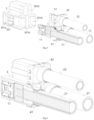
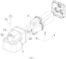
- Figure 14 shows an illustrative exploded view of a connector according to an exemplary embodiment of the present invention when viewed from the bottom;
- Figure 15 shows an illustrative exploded view of a connector according to an exemplary embodiment of the present invention when viewed from the top;
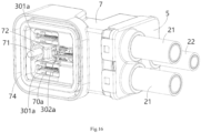
- Figure 16 shows an illustrative perspective view of a connector according to an exemplary embodiment of the present invention when viewed from the bottom;
- Figure 17 shows a longitudinal sectional view of a connector according to an exemplary embodiment of the present invention.
- a connector is also disclosed.
- the connector includes an outer shielding shell 7 and an electrical connection module 100.
- An installation chamber 70 is formed in the outer shielding shell 7.
- the electrical connection module 100 is inserted into the installation chamber 70 of the outer shielding shell 7.
- the outer shielding shell 7 has an installation portion 72 embedded in the wall recess 32 of the inner housing 3, and a connection hole 73 extending along the height direction Z of the outer shielding shell 7 is formed in the installation portion 72.
- the connector also includes a bolt 71, which passes through the connection hole 73 and is suitable for threaded connection to the threaded hole of the mating outer shielding shell to fasten the connector to the mating connector.
- the bolt 71 passes through the wall recess 32 of the inner housing 3. Therefore, the bolt 71 is closer to the center of the inner housing 3, which can reduce the length of the force arm and effectively prevent the connector from experiencing force imbalance.
- the outer shielding shell 7 has front and rear ends opposite in its longitudinal direction Y, and bottom and top sides opposite in its height direction Z.
- the installation chamber 70 has a rear port 70b located at the rear end of the outer shielding shell 7.
- the electrical connection module 100 is inserted into the installation chamber 70 through the rear port 70b, and the first cable 21 and the second cable 22 of the electrical connection module 100 extend out of the rear port 70b along the longitudinal direction Y
- the installation chamber 70 also has a bottom port 70a located on the bottom side of the front end of the outer shielding shell 7.
- the first insertion port 301a and the second insertion port 302a of the inner housing 3 of the electrical connection module 100 are located in the bottom port 70a, so that the first mating terminal and the second mating terminal can be respectively inserted into the first insertion port 301a and the second insertion port 302a of the inner housing 3 along the height direction Z through the bottom port 70a.
- the connector further includes a sealing ring 74, which is set in the bottom port 70a of the outer shielding shell 7 and is suitable for being compressed between the outer shielding shell 7 and the mating outer shielding shell to achieve sealing between the two.
Landscapes
- Connector Housings Or Holding Contact Members (AREA)
Abstract
The present invention discloses an electrical connection module and a connector. The electrical connection module comprises of: an inner housing (3) which is formed with a pair of first terminal slots (301) extending along its longitudinal direction (Y) and a second terminal slot (302) extending along its height direction (Z), and has opposite front and rear ends in its longitudinal direction (Y); a pair of first terminals (11) which are respectively inserted into the pair of first terminal slots (301), and their length and width directions are parallel to the longitudinal direction (Y) and the height direction (Z), respectively; and a second terminal (12) which is inserted into the second terminal slot (302) and its length direction and width direction are parallel to the height direction (Z) and the longitudinal direction (Y), respectively. The pair of first terminal slots (301) are arranged side by side in a transverse direction (X) of the inner housing (3), and the second terminal slot (302) is located between the pair of first terminal slots (301), the first terminal slot (301) extends forward along the longitudinal direction (Y) beyond the second terminal slot (302), and the second terminal slot (302) extends upward along the height direction (Z) beyond the first terminal slot (301); the first terminal slot (301) has a first insertion port (301a) formed on the bottom of the inner housing (3), the second terminal slot (302) has a second insertion port (302a) formed on the bottom of the inner housing (3) and offset from the first insertion port (301a) in the longitudinal direction (Y); the first terminal (11) is used to mate with a first mating terminal inserted into the first insertion port (301a) along the height direction (Z), and the second terminal (12) is used to mate with a second mating terminal inserted into the second insertion port (302a) along the height direction (Z). The present invention can save the layout space of three terminals, thereby reducing the size of the electrical connection module and connector.
Description
- This application claims the benefit of Chinese Patent Application No.
CN202410008596.3 filed on January 2, 2024 - The present invention relates to an electrical connection module and a connector comprising the electrical connection module.
- In the prior art, it is often necessary to use a 90 degree connector (also known as a right angle connector), which has a cable lead direction perpendicular to the mating direction of the terminals. In the prior art, when the connector has multiple terminals and cables, the multiple terminals are usually arranged side by side in the cable lead direction, and the multiple cables are usually arranged side by side in the mating direction of terminals. This arrangement can lead to the connector being too large in size.
- The present invention has been made to overcome or alleviate at least one aspect of the above mentioned disadvantages.
- According to an aspect of the present invention, there is provided an electrical connection module. The electrical connection module comprises of an inner housing which is formed with a pair of first terminal slots extending along its longitudinal direction and a second terminal slot extending along its height direction, and has opposite front and rear ends in its longitudinal direction; a pair of first terminals which are respectively inserted into the pair of first terminal slots, and their length and width directions are parallel to the longitudinal direction and the height direction, respectively; and a second terminal which is inserted into the second terminal slot and its length direction and width direction are parallel to the height direction and the longitudinal direction, respectively. The pair of first terminal slots are arranged side by side in a transverse direction of the inner housing, and the second terminal slot is located between the pair of first terminal slots, the first terminal slot extends forward along the longitudinal direction beyond the second terminal slot, and the second terminal slot extends upward along the height direction beyond the first terminal slot, the first terminal slot has a first insertion port formed on the bottom of the inner housing, the second terminal slot has a second insertion port formed on the bottom of the inner housing and offset from the first insertion port in the longitudinal direction, the first terminal is used to mate with a first mating terminal inserted into the first insertion port along the height direction, and the second terminal is used to mate with a second mating terminal inserted into the second insertion port along the height direction.
- According to an exemplary embodiment of the present invention, the first terminal comprises a first terminal body, which has a first mating part and a first connection part opposite to each other in the longitudinal direction of the inner housing; the first mating part has a first mating port facing the first insertion port for mating with the first mating terminal, and the first connection part is used for electrical connection with a first cable introduced along the longitudinal direction; the second terminal comprises a second terminal body, which has a second mating part and a second connection part opposite to each other in the height direction of the inner housing; the second mating part has a second mating port facing the second insertion port for mating with the second mating terminal, and the second connection part is used for electrical connection with a second cable introduced along the longitudinal direction.
- According to another exemplary embodiment of the present invention, a pair of first cable holes that are respectively communicated with the pair of first terminal slots are formed in the rear end of the inner housing to allow a pair of first cables to be introduced along the longitudinal direction, and a second cable hole that is communicated with the second terminal slot is formed in the rear end of the inner housing to allow a second cable to be introduced along the longitudinal direction; the pair of first cable holes are arranged side by side in the transverse direction of the inner housing, and the second cable hole is located between and above the pair of first cable holes.
- According to another exemplary embodiment of the present invention, the electrical connection module further comprises of a pair of first cables which are respectively introduced from the pair of first cable holes along the longitudinal direction and electrically connected to the first connection parts of the pair of first terminals; and a second cable which is introduced along the longitudinal direction from the second cable hole and electrically connected to the second connection part of the second terminal. The pair of first cables are arranged side by side in the transverse direction of the inner housing, and the second cable is located between and above the pair of first cables.
- According to another exemplary embodiment of the present invention, the first cable has a first conductor end electrically connected to the first connection part of the first terminal body, and the second cable has a second conductor end electrically connected to the second connection part of the second terminal body; the first conductor ends of the pair of first cables are arranged side by side in the transverse direction of the inner housing, and the second conductor end of the second cable is located between and above the first conductor ends of the pair of first cables.
- According to another exemplary embodiment of the present invention, the first mating part and the first connection part are respectively located at both ends of the length direction of the first terminal body, and the length direction and width direction of the first terminal body are parallel to the longitudinal direction and height direction of the inner housing, respectively; the second mating part and the second connection part are respectively located at both ends of the length direction of the second terminal body, and the length direction and width direction of the second terminal body are parallel to the height direction and longitudinal direction of the inner housing, respectively.
- According to another exemplary embodiment of the present invention, the thickness direction of the first terminal body is perpendicular to the longitudinal direction and height direction of the inner housing, the first mating part includes a first top wall plate and a first bottom wall plate spaced opposite each other in the thickness direction of the first terminal body, a first slot is defined between the first top wall plate and the first bottom wall plate to allow the insertion of the first mating terminal.
- According to another exemplary embodiment of the present invention, the thickness direction of the second terminal body is perpendicular to the longitudinal direction and height direction of the inner housing, and the second mating part includes a second top wall plate and a second bottom wall plate spaced opposite each other in the thickness direction of the second terminal body, a second slot is defined between the second top wall plate and the second bottom wall plate to allow the insertion of the second mating terminal.
- According to another exemplary embodiment of the present invention, the first terminal further comprises a pair of first terminal contacts which are respectively installed on the inner sides of the first top wall plate and the first bottom wall plate of the first mating parts, the first terminal contact has multiple first elastic contact arms arranged in a row in the longitudinal direction and extending in the height direction for electrical contact with the first mating terminal inserted along the height direction.
- According to another exemplary embodiment of the present invention, the second terminal further comprises a pair of second terminal contacts which are respectively installed on the inner sides of the second top wall plate and the second bottom wall plate of the second mating part, the second terminal contact has multiple second elastic contact arms arranged in a row in the longitudinal direction and extending in the height direction, for electrical contact with the second mating terminal inserted along the height direction.
- According to another exemplary embodiment of the present invention, the first terminal further comprises a first terminal limiting member which is U-shaped and is fitted onto the end of the first mating part to ensure that the distance between the first top wall plate and the first bottom wall plate is equal to a predetermined value.
- According to another exemplary embodiment of the present invention, the first terminal limiting member comprises: a first top plate which is attached to the outer side of the first top wall plate; a first bottom plate which is attached to the outer side of the first bottom wall plate; and a first side plate which is connected between the first top plate and the first bottom plate and is attached to the end face of the first mating part.
- According to another exemplary embodiment of the present invention, the first top plate and the first bottom plate have opposite sides in the width direction of the first terminal body, first elastic buckles with a C-shaped cross-section are respectively formed on both sides of the first top plate and the first bottom plate, and first snap slots corresponding to the first elastic buckles are formed on the edges of both sides of the first top wall plate and the first bottom wall plate, the first elastic buckles are engaged into the first snap slots to fix the first terminal limiting member to the first mating part.
- According to another exemplary embodiment of the present invention, first elastic locking pieces are respectively formed on the first top plate and the first bottom plate, and the first elastic locking pieces are engaged with the inner housing to lock the first terminal into the inner housing; first guide ribs extending along the longitudinal direction are respectively formed on the first top plate and the first bottom plate, the first guide ribs are used to cooperate with first guide slots in the inner housing to guide the first terminal to be inserted into the inner housing along the longitudinal direction.
- According to another exemplary embodiment of the present invention, the second terminal further comprises a second terminal limiting member which is annular in shape and is fitted onto the end of the second mating part to ensure that the distance between the second top wall plate and the second bottom wall plate is equal to a predetermined value.
- According to another exemplary embodiment of the present invention, the second terminal limiting member comprises: a second top plate which is attached to the outer side of the second top wall plate; a second bottom plate which is attached to the outer side of the second bottom wall plate; and two second side plates connected between the second top plate and the second bottom plate. The second top plate and the second bottom plate have opposite sides in the width direction of the second terminal body, one second side plate is connected between one side of the second top plate and the second bottom plate and is attached to one side of the second mating part, while the other second side plate is connected between the other side of the second top plate and the second bottom plate and is attached to the other side of the second mating part.
- According to another exemplary embodiment of the present invention, second elastic buckles with a C-shaped cross-section are respectively formed on both sides of the second top plate and the second bottom layer plate, second snap slots corresponding to the second elastic buckles are respectively formed on the left and right edges of the second top wall plate and the second bottom wall plate, the second elastic buckles are engaged into the second snap slots to fix the second terminal limiting member to the second mating part.
- According to another exemplary embodiment of the present invention, second elastic locking pieces are respectively formed on the second top plate and the second bottom plate, and the second elastic locking pieces are engaged with the inner housing to lock the second terminal into the inner housing; second guide ribs extending along the height direction are respectively formed on the second top plate and the second bottom plate, the second guide ribs are used to cooperate with second guide slots in the inner housing to guide the second terminal to be inserted into the inner housing along the height direction.
- According to another exemplary embodiment of the present invention, the first connection part comprises a first top layer plate and a first bottom layer plate stacked and riveted together in the thickness direction of the first terminal body, the first top layer plate and the first bottom layer plate are respectively connected to the first top wall plate and the first bottom wall plate, and the first conductor end is flat and stacked and welded on the first top layer plate or the first bottom layer plate.
- According to another exemplary embodiment of the present invention, the second connection part comprises a second top layer plate and a second bottom layer plate stacked and riveted together in the thickness direction of the second terminal body, the second top layer plate and the second bottom layer plate are respectively connected to the second top wall plate and the second bottom wall plate, the second conductor end is flat and stacked and welded on the second top layer plate or the second bottom layer plate.
- According to another exemplary embodiment of the present invention, the inner housing comprises: a main body which has a top opening communicated with the second terminal slot and the second cable hole; and a top cover which is installed on the top of the main body to close the top opening of the main body, the second terminal and the second cable are inserted into the main body of the inner housing through the top opening of the main body.
- According to another exemplary embodiment of the present invention, the electrical connection module further comprises of a first shielding sleeve which is used to electrically connect a shielding layer of the first cable to an outer shielding shell of the connector; and a second shielding sleeve which is fitted onto the second cable for electrically connecting a shielding layer of the second cable to the outer shielding shell.
- According to another exemplary embodiment of the present invention, the electrical connection module further comprises a rear end cover adapted to be locked to the rear end of the outer shielding shell of the connector, to fix the first cable and the second cable to the outer shielding shell, a through-hole is formed in the rear end cover to allow the first cable and the second cable to pass through.
- According to another exemplary embodiment of the present invention, the electrical connection module further comprises of a first end cap which is installed on the first insertion port of the inner housing and formed with a first guide port for guiding the first mating terminal to be inserted into the first insertion port; and a second end cap which is installed on the second insertion port of the inner housing and formed with a second guide port for guiding the second mating terminal to be inserted into the second insertion port.
- According to another exemplary embodiment of the present invention, a wall recess is formed on the outer side of the front end of the inner housing, which is located between the front ends of the pair of first terminal slots and in front of the second terminal slot; the wall recess is used to cooperate with an installation portion of the outer shielding shell of the connector, so that the connector can be fastened to a mating outer shielding shell by a bolt passing through the installation portion of the outer shielding shell along the height direction.
- According to another aspect of the present invention, there is provided a connector. The connector comprises of an outer shielding shell which is formed with an installation chamber; and the above electrical connection module inserted into the installation chamber of the outer shielding shell.
- According to an exemplary embodiment of the present invention, the outer shielding shell has an installation portion embedded in the wall recess of the inner housing, and a connection hole extending along the height direction of the outer shielding shell is formed in the installation portion; the connector further comprises a bolt that passes through the connection hole and is adapted to be threaded into a threaded hole of the mating outer shielding shell to fasten the connector to a mating connector.
- According to another exemplary embodiment of the present invention, the outer shielding shell has front and rear ends that are opposite in its longitudinal direction, and bottom and top sides that are opposite in its height direction; the installation chamber has a rear port located at the rear end of the outer shielding shell, and the electrical connection module is inserted into the installation chamber through the rear port, the first cable and the second cable of the electrical connection module extend out of the rear port along the longitudinal direction; the installation chamber also has a bottom port located on the bottom of the front end of the outer shielding shell, and the first insertion port and the second insertion port of the inner housing of the electrical connection module are located in the bottom port, so that the first mating terminal and the second mating terminal can be respectively inserted into the first insertion port and the second insertion port of the inner housing along the height direction through the bottom port.
- According to another exemplary embodiment of the present invention, the connector further comprises a sealing ring which is set in the bottom port of the outer shielding shell and is suitable for being compressed between the outer shielding shell and the mating outer shielding shell to achieve sealing between the two.
- In the aforementioned exemplary embodiments according to the present invention, the second terminal slot is located between the pair of first terminal slots and is offset from the pair of first terminal slots by a predetermined distance in the longitudinal direction of the inner housing. This layout can save the arrangement space of three terminals, thereby reducing the size of the electrical connection module and connector.
- In the aforementioned exemplary embodiments according to the present invention, since the second terminal slot is offset by a predetermined distance from the pair of first terminal slots in the longitudinal direction of the inner housing, a wall recess facing the second terminal slot can be formed on the inner housing to allow the bolt used to fasten the connector to the mating connector to pass through the wall recess, so that the bolt is closer to the center of the connector, effectively preventing the connector from being subjected to unbalanced forces.
- The above and other features of the present invention will become more apparent by describing in detail exemplary embodiments thereof with reference to the accompanying drawings, in which:
-
Figure 1 shows an illustrative perspective view of an electrical connection module according to an exemplary embodiment of the present invention when viewed from the top; -
Figure 2 shows an illustrative perspective view of an electrical connection module according to an exemplary embodiment of the present invention when viewed from the bottom; -
Figure 3 shows an illustrative exploded view of an electrical connection module according to an exemplary embodiment of the present invention when viewed from the bottom; -
Figure 4 shows an illustrative perspective view of the inner housing and end cap of an electrical connection module according to an exemplary embodiment of the present invention; -
Figure 5 shows an exploded sectional view of an electrical connection module according to an exemplary embodiment of the present invention; -
Figure 6 shows an assembled sectional view of an electrical connection module according to an exemplary embodiment of the present invention; -
Figure 7 shows another exploded sectional view of an electrical connection module according to an exemplary embodiment of the present invention; -
Figure 8 shows another assembly sectional view of an electrical connection module according to an exemplary embodiment of the present invention; -
Figure 9 shows an illustrative exploded view of the inner housing of an electrical connection module according to an exemplary embodiment of the present invention; -
Figure 10 shows an illustrative perspective view of the first terminal and first cable of an electrical connection module according to an exemplary embodiment of the present invention; -
Figure 11 shows an illustrative perspective view of the first terminal of an electrical connection module according to an exemplary embodiment of the present invention; -
Figure 12 shows an illustrative perspective view of the second terminal and second cable of an electrical connection module according to an exemplary embodiment of the present invention; -
Figure 13 shows an illustrative perspective view of the second terminal of an electrical connection module according to an exemplary embodiment of the present invention; -
Figure 14 shows an illustrative exploded view of a connector according to an exemplary embodiment of the present invention when viewed from the bottom; -
Figure 15 shows an illustrative exploded view of a connector according to an exemplary embodiment of the present invention when viewed from the top; -
Figure 16 shows an illustrative perspective view of a connector according to an exemplary embodiment of the present invention when viewed from the bottom; and -
Figure 17 shows a longitudinal sectional view of a connector according to an exemplary embodiment of the present invention. - Exemplary embodiments of the present disclosure will be described hereinafter in detail with reference to the attached drawings, wherein the like reference numerals refer to the like elements. The present disclosure may, however, be embodied in many different forms and should not be construed as being limited to the embodiment set forth herein; rather, these embodiments are provided so that the present disclosure will be thorough and complete, and will fully convey the concept of the disclosure to those skilled in the art.
- In the following detailed description, for purposes of explanation, numerous specific details are set forth in order to provide a thorough understanding of the disclosed embodiments. It will be apparent, however, that one or more embodiments may be practiced without these specific details. In other instances, well-known structures and devices are schematically shown in order to simplify the drawing.
- According to a general concept of the present invention, there is provided an electrical connection module. The electrical connection module comprises of an inner housing which is formed with a pair of first terminal slots extending along its longitudinal direction and a second terminal slot extending along its height direction, and has opposite front and rear ends in its longitudinal direction; a pair of first terminals which are respectively inserted into the pair of first terminal slots, and their length and width directions are parallel to the longitudinal direction and the height direction, respectively; and a second terminal which is inserted into the second terminal slot and its length direction and width direction are parallel to the height direction and the longitudinal direction, respectively. The pair of first terminal slots are arranged side by side in a transverse direction of the inner housing, and the second terminal slot is located between the pair of first terminal slots, the first terminal slot extends forward along the longitudinal direction beyond the second terminal slot, and the second terminal slot extends upward along the height direction beyond the first terminal slot, the first terminal slot has a first insertion port formed on the bottom of the inner housing, the second terminal slot has a second insertion port formed on the bottom of the inner housing and offset from the first insertion port in the longitudinal direction, the first terminal is used to mate with a first mating terminal inserted into the first insertion port along the height direction, and the second terminal is used to mate with a second mating terminal inserted into the second insertion port along the height direction.
- According to another general concept of the present invention, there is provided a connector. The connector comprises of: an outer shielding shell which is formed with an installation chamber; and the above electrical connection module inserted into the installation chamber of the outer shielding shell.
-
Figure 1 shows an illustrative perspective view of anelectrical connection module 100 according to an exemplary embodiment of the present invention when viewed from the top;Figure 2 shows an illustrative perspective view of theelectrical connection module 100 according to an exemplary embodiment of the present invention when viewed from the bottom;Figure 3 shows an illustrative exploded view of theelectrical connection module 100 according to an exemplary embodiment of the present invention when viewed from the bottom;Figure 4 shows an illustrative perspective view of theinner housing 3 and endcaps electrical connection module 100 according to an exemplary embodiment of the present invention;Figure 5 shows an exploded cross-sectional view of anelectrical connection module 100 according to an exemplary embodiment of the present invention;Figure 6 shows an assembled sectional view of anelectrical connection module 100 according to an exemplary embodiment of the present invention;Figure 7 shows another exploded cross-sectional view of theelectrical connection module 100 according to an exemplary embodiment of the present invention;Figure 8 shows another assembly sectional view of theelectrical connection module 100 according to an exemplary embodiment of the present invention. - As shown in
Figures 1 to 8 , in an exemplary embodiment of the present invention, anelectrical connection module 100 is disclosed. Theelectrical connection module 100 includes aninner housing 3, a pair offirst terminals 11, and asecond terminal 12. A pair of firstterminal slots 301 extending along a longitudinal direction Y of theinner housing 3 and a secondterminal slot 302 extending along a height direction Z of theinner housing 3 are formed in theinner housing 3. Theinner housing 3 has front and rear ends that are opposite in its longitudinal direction Y The pair offirst terminals 11 are respectively inserted into the pair of firstterminal slots 301, and the length and width directions of thefirst terminals 11 are parallel to the longitudinal Y and height Z directions of theinner housing 3, respectively. Thesecond terminal 12 is inserted into the secondterminal slot 302, and the length and width directions of thesecond terminal 12 are parallel to the height direction Z and longitudinal direction Y of theinner housing 3, respectively. - As shown in
Figures 1 to 8 , in the illustrated embodiment, the pair of firstterminal slots 301 are arranged side by side in the transverse direction X of theinner housing 3, and a secondterminal slot 302 is located between the pair of firstterminal slots 301. The firstterminal slot 301 extends forward along the longitudinal direction Y beyond the secondterminal slot 302, and the secondterminal slot 302 extends upward along the height direction Z beyond the firstterminal slot 301. The firstterminal slot 301 has afirst insertion port 301a formed on the bottom side of theinner housing 3, the secondterminal slot 302 has asecond insertion port 302a formed on the bottom side of theinner housing 3. Thesecond insertion port 302a is offset from thefirst insertion port 301a in the longitudinal direction (Y). Thefirst terminal 11 is used to mate with a first mating terminal (not shown) inserted into thefirst insertion port 301a along the height direction Z, and thesecond terminal 12 is used to mate with a second mating terminal (not shown) inserted into thesecond insertion port 302a along the height direction Z. -
Figure 9 shows an illustrative exploded view of theinner housing 3 of theelectrical connection module 100 according to an exemplary embodiment of the present invention;Figure 10 shows an illustrative perspective view of thefirst terminal 11 and thefirst cable 21 of theelectrical connection module 100 according to an exemplary embodiment of the present invention;Figure 11 shows an illustrative perspective view of thefirst terminal 11 of theelectrical connection module 100 according to an exemplary embodiment of the present invention;Figure 12 shows an illustrative perspective view of thesecond terminal 12 and thesecond cable 22 of theelectrical connection module 100 according to an exemplary embodiment of the present invention;Figure 13 shows an illustrative perspective view of thesecond terminal 12 of theelectrical connection module 100 according to an exemplary embodiment of the present invention. - As shown in
Figures 1 to 13 , in the illustrated embodiment, thefirst terminal 11 includes a firstterminal body 110. The firstterminal body 110 has afirst mating part 111 and afirst connection part 112 that are opposite to each other in the longitudinal direction Y of theinner housing 3. Thefirst mating part 111 has afirst mating port 111a facing thefirst insertion port 301a for mating with the first mating terminal, and thefirst connection part 112 is used for electrical connection with afirst cable 21 introduced along the longitudinal direction Y. Thesecond terminal 12 includes a secondterminal body 120, which has asecond mating part 121 and asecond connection part 122 that are opposite to each other in the height direction Z of theinner housing 3. Thesecond mating part 121 has asecond mating port 121a facing thesecond insertion port 302a for mating with the second mating terminal, and thesecond connection part 122 is used for electrically connecting with asecond cable 22 introduced along the longitudinal direction Y. - As shown in
Figures 1 to 13 , in the illustrated embodiment, a pair offirst cable holes 301b are formed in the rear end of theinner housing 3, which are respectively communicated with the pair of firstterminal slots 301 to allow a pair offirst cables 21 to be introduced along the longitudinal direction Y. Asecond cable hole 302b is formed in the rear end of theinner housing 3, which is communicated with the secondterminal slot 302 to allow asecond cable 22 to be introduced along the longitudinal direction Y The pair offirst cable holes 301b are arranged side by side in the transverse direction X of theinner housing 3, and asecond cable hole 302b is located between and above the pair offirst cable holes 301b. - As shown in
Figures 1 to 13 , in the illustrated embodiment, theelectrical connection module 100 further includes a pair offirst cables 21 and asecond cable 22. The pair offirst cables 21 are respectively introduced from the pair of first cable holes 301b along the longitudinal direction Y and electrically connected to thefirst connection parts 112 of the pair offirst terminals 11. Thesecond cable 22 is introduced along the longitudinal direction Y from thesecond cable hole 302b and electrically connected to thesecond connection part 122 of thesecond terminal 12. The pair offirst cables 21 are arranged side by side in the transverse direction X of theinner housing 3, and thesecond cable 22 is located between and above the pair offirst cables 21. - As shown in
Figures 1 to 13 , in the illustrated embodiment, thefirst cable 21 has afirst conductor end 211 electrically connected to thefirst connection part 112 of the firstterminal body 110, and thesecond cable 22 has asecond conductor end 221 electrically connected to thesecond connection part 122 of the secondterminal body 120. The first conductor ends 211 of the pair offirst cables 21 are arranged side by side in the transverse direction X of theinner housing 3, and thesecond conductor end 221 of thesecond cable 22 is located between and above the first conductor ends 211 of the pair offirst cables 21. - As shown in
Figures 1 to 13 , in the illustrated embodiment, thefirst mating part 111 and thefirst connection part 112 are located at both ends of the length direction of the firstterminal body 110, and the length direction and width direction of the firstterminal body 110 are parallel to the longitudinal direction Y and height direction Z of theinner housing 3, respectively. Thesecond mating part 121 and thesecond connection part 122 are located at both ends of the length direction of the secondterminal body 120, and the length direction and width direction of the secondterminal body 120 are parallel to the height direction Z and longitudinal direction Y of theinner housing 3, respectively. - As shown in
Figures 1 to 13 , in the illustrated embodiment, the thickness direction of the firstterminal body 110 is perpendicular to the longitudinal direction Y and height direction Z of theinner housing 3. Thefirst mating part 111 includes a firsttop wall plate 11a and a firstbottom wall plate 11b spaced opposite each other in the thickness direction of the firstterminal body 110, and afirst slot 11c is defined between the firsttop wall plate 11a and the firstbottom wall plate 11b to allow the insertion of the first mating terminal. - As shown in
Figures 1 to 13 , in the illustrated embodiment, the thickness direction of the secondterminal body 120 is perpendicular to the longitudinal direction Y and height direction Z of theinner housing 3. Thesecond mating part 121 includes a secondtop wall plate 12a and a secondbottom wall plate 12b spaced opposite each other in the thickness direction of the secondterminal body 120, and asecond slot 12c is defined between the secondtop wall plate 12a and the secondbottom wall plate 12b to allow the insertion of the second mating terminal. - As shown in
Figures 1 to 13 , in the illustrated embodiment, thefirst terminal 11 further includes a pair of firstterminal contacts 101, which are respectively installed on the inner sides of the firsttop wall plate 11a and the firstbottom wall plate 11b of thefirst mating parts 111. The firstterminal contact 101 has multiple firstelastic contact arms 101a, which are arranged in a row along the longitudinal direction Y and extend in the height direction Z, for electrical contact with the first mating terminal inserted along the height direction Z. - As shown in
Figures 1 to 13 , in the illustrated embodiment, thesecond terminal 12 further includes a pair of secondterminal contacts 102, which are respectively installed on the inner sides of the secondtop wall plate 12a and the secondbottom wall plate 12b of thesecond mating parts 121. The secondterminal contact 102 has multiple secondelastic contact arms 102a, which are arranged in a row along the longitudinal direction Y and extend in the height direction Z, for electrical contact with a second mating terminals inserted along the height direction Z. - As shown in
Figures 1 to 13 , in the illustrated embodiment, thefirst terminal 11 further includes a firstterminal limiting member 103, which is U-shaped and fitted onto the end of thefirst mating part 111 to ensure that the distance between the firsttop wall plate 11a and the firstbottom wall plate 11b is equal to a predetermined value. - As shown in
Figures 1 to 13 , in the illustrated embodiment, the firstterminal limiting member 103 includes a firsttop plate 103a, afirst bottom plate 103b, and afirst side plate 103c. The firsttop plate 103a is attached to the outer side of the firsttop wall plate 11a. Thefirst bottom plate 103b is attached to the outer side of the firstbottom wall plate 11b. Thefirst side plate 103c is connected between the firsttop plate 103a and thefirst bottom plate 103b and is attached to the end face of thefirst mating part 111. - As shown in
Figures 1 to 13 , in the illustrated embodiment, the firsttop plate 103a and thefirst bottom plate 103b have opposite sides in the width direction of the firstterminal body 110. Firstelastic buckles 103f with a C-shaped cross-section are respectively formed on both sides of the firsttop plate 103a and thefirst bottom plate 103b, andfirst snap slots 11f corresponding to the firstelastic buckles 103f are respectively formed on the edges of the firsttop wall plate 11a and the firstbottom wall plate 11b. The firstelastic buckles 103f are engaged in thefirst snap slots 11f to fix the firstterminal limiting member 103 to thefirst mating part 111. - As shown in
Figures 1 to 13 , in the illustrated embodiment, firstelastic locking pieces 103d are formed on the firsttop plate 103a and thefirst bottom plate 103b, respectively. The firstelastic locking pieces 103d are engaged with theinner housing 3 to lock thefirst terminal 11 into theinner housing 3.First guide ribs 103e extending along the longitudinal direction Y are respectively formed on the firsttop plate 103a and thefirst bottom plate 103b. Thefirst guide ribs 103e are used to cooperate with first guide slots in theinner housing 3 to guide thefirst terminal 11 to be inserted into theinner housing 3 along the longitudinal direction Y. - As shown in
Figures 1 to 13 , in the illustrated embodiment, thesecond terminal 12 further includes a secondterminal limiting member 104, which is annular in shape and is fitted onto the end of thesecond mating part 121 to ensure that the distance between the secondtop wall plate 12a and the secondbottom wall plate 12b is equal to a predetermined value. - As shown in
Figures 1 to 13 , in the illustrated embodiment, the secondterminal limiting member 104 includes a secondtop plate 104a, asecond bottom plate 104b, and twosecond side plates 104c. The secondtop plate 104a is attached to the outer side of the secondtop wall plate 12a. The second bottom plate 14b is attached to the outer side of the secondbottom wall plate 12b. Twosecond side plates 104c are connected between the secondtop plate 104a and thesecond bottom plate 104b. The secondtop plate 104a and thesecond bottom plate 104b have opposite sides in the width direction of the secondterminal body 120. Onesecond side plate 104c is connected between one side of the secondtop plate 104a and thesecond bottom plate 104b, and is attached to one side of thesecond mating part 121. The othersecond side plate 104c is connected between the other side of the secondtop plate 104a and thesecond bottom plate 104b, and is attached to the other side of thesecond mating part 121. - As shown in
Figures 1 to 13 , in the illustrated embodiment, secondelastic buckles 104f with a C-shaped cross-section are respectively formed on both sides of the secondtop plate 104a and thesecond bottom plate 104b, andsecond snap slots 12f corresponding to the secondelastic buckles 104f are respectively formed on the edges of the left and right sides of the secondtop wall plate 12a and the secondbottom wall plate 12b. The secondelastic buckles 104f are engaged into thesecond snap slots 12f to fix the secondterminal limiting member 104 to thesecond mating part 121. - As shown in
Figures 1 to 13 , in the illustrated embodiment, secondelastic locking pieces 104d are formed on the secondtop plate 104a and thesecond bottom plate 104b, respectively. The secondelastic locking pieces 104d are engaged with theinner housing 3 to lock thesecond terminal 12 into theinner housing 3.Second guide ribs 104e extending along the height direction Z are formed on the secondtop plate 104a and thesecond bottom plate 104b, respectively. Thesecond guide ribs 104e are used to cooperate with the second guide slots in theinner housing 3 to guide thesecond terminal 12 to be inserted into theinner housing 3 along the height direction Z. - As shown in
Figures 1 to 13 , in the illustrated embodiment, thefirst connection part 112 includes a firsttop layer plate 12a and a firstbottom layer plate 12b stacked and riveted together in the thickness direction of the firstterminal body 110. The firsttop layer plate 12a and the firstbottom layer plate 12b are connected to the firsttop wall plate 11a and the firstbottom wall plate 11b, respectively. Thefirst conductor end 211 is flat and stacked and welded on the firsttop layer plate 12a or the firstbottom layer plate 12b. - As shown in
Figures 1 to 13 , in the illustrated embodiment, thesecond connection part 122 includes a secondtop layer plate 122a and a secondbottom layer plate 122b stacked and riveted together in the thickness direction of the secondterminal body 120. The secondtop layer plate 122a and the secondbottom layer plate 122b are connected to the secondtop wall plate 12a and the secondbottom wall plate 12b, respectively. Thesecond conductor end 221 is flat and stacked and welded on the secondtop layer plate 122a or the secondbottom layer plate 122b. - As shown in
Figures 1 to 13 , in the illustrated embodiment, theinner housing 3 includes amain body 3a and atop cover 3b. Atop opening is formed at the top of themain body 3a, which is communicated with the secondterminal slot 302 and thesecond cable hole 302b. Thetop cover 3b is installed on the top of themain body 3a to close the top opening of themain body 3a. Thesecond terminal 12 and thesecond cable 22 are inserted into themain body 3a of theinner housing 3 through the top opening of themain body 3a. - As shown in
Figures 1 to 13 , in the illustrated embodiment, theelectrical connection module 100 further includes afirst shielding sleeve 41 and asecond shielding sleeve 42. Thefirst shielding sleeve 41 is used to electrically connect the shielding layer of thefirst cable 21 to theouter shielding shell 7 of the connector. Thesecond shielding sleeve 42 is fitted onto thesecond cable 22, used to electrically connect the shielding layer of thesecond cable 22 to theouter shielding shell 7. In the illustrated embodiment, the front ends of thefirst shielding sleeve 41 and thesecond shielding sleeve 42 are fitted onto the rear end of theinner housing 3, and the rear ends of thefirst shielding sleeve 41 and thesecond shielding sleeve 42 are respectively fitted and crimped onto the shielding layers of thefirst cable 21 and thesecond cable 22. - As shown in
Figures 1 to 13 , in the illustrated embodiment, theelectrical connection module 100 further includes arear end cover 5, which is adapted to be locked onto the rear end of theouter shielding shell 7 of the connector to fix thefirst cable 21 and thesecond cable 22 to theouter shielding shell 7. A through-hole is formed in therear cover 5 to allow thefirst cable 21 and thesecond cable 22 to pass through. - Although not shown, in an exemplary embodiment of the present invention, the
electrical connection module 100 may further include a sealing member that can be installed into therear port 70b of theouter shielding shell 7 to seal therear port 70b of theouter shielding shell 7. There are through holes formed on the seal that allow thefirst cable 21 and thesecond cable 22 to pass through. - As shown in
Figures 1 to 13 , in the illustrated embodiment, theelectrical connection module 100 further includes afirst end cap 33 and asecond end cap 34. Thefirst end cap 33 is installed on thefirst insertion port 301a of theinner housing 3 and is formed with afirst guide port 33a for guiding the first mating terminal to be inserted into thefirst insertion port 301a. Thesecond end cap 34 is installed on thesecond insertion port 302a of theinner housing 3 and formed with asecond guide port 34a for guiding the second mating terminal to be inserted into thesecond insertion port 302a. - As shown in
Figures 1 to 13 , in the illustrated embodiment, awall recess 32 is formed on the outer side of the front end of theinner housing 3. Thewall recess 32 is located between the front ends of the pair of firstterminal slots 301 and in front of the secondterminal slot 302. Thewall recess 32 is used to mate with theinstallation portion 72 of theouter shielding shell 7 of the connector, so that the connector can be fastened to a mating outer shielding shell (not shown) by abolt 71 passing through theinstallation portion 72 of theouter shielding shell 7 along the height direction Z. -
Figure 14 shows an illustrative exploded view of a connector according to an exemplary embodiment of the present invention when viewed from the bottom;Figure 15 shows an illustrative exploded view of a connector according to an exemplary embodiment of the present invention when viewed from the top;Figure 16 shows an illustrative perspective view of a connector according to an exemplary embodiment of the present invention when viewed from the bottom;Figure 17 shows a longitudinal sectional view of a connector according to an exemplary embodiment of the present invention. - As shown in
Figures 1 to 17 , in another exemplary embodiment of the present invention, a connector is also disclosed. The connector includes anouter shielding shell 7 and anelectrical connection module 100. Aninstallation chamber 70 is formed in theouter shielding shell 7. Theelectrical connection module 100 is inserted into theinstallation chamber 70 of theouter shielding shell 7. - As shown in
Figures 1 to 17 , in the illustrated embodiment, theouter shielding shell 7 has aninstallation portion 72 embedded in thewall recess 32 of theinner housing 3, and aconnection hole 73 extending along the height direction Z of theouter shielding shell 7 is formed in theinstallation portion 72. The connector also includes abolt 71, which passes through theconnection hole 73 and is suitable for threaded connection to the threaded hole of the mating outer shielding shell to fasten the connector to the mating connector. In the illustrated embodiment, thebolt 71 passes through thewall recess 32 of theinner housing 3. Therefore, thebolt 71 is closer to the center of theinner housing 3, which can reduce the length of the force arm and effectively prevent the connector from experiencing force imbalance. - As shown in
Figures 1 to 17 , in the illustrated embodiment, theouter shielding shell 7 has front and rear ends opposite in its longitudinal direction Y, and bottom and top sides opposite in its height direction Z. Theinstallation chamber 70 has arear port 70b located at the rear end of theouter shielding shell 7. Theelectrical connection module 100 is inserted into theinstallation chamber 70 through therear port 70b, and thefirst cable 21 and thesecond cable 22 of theelectrical connection module 100 extend out of therear port 70b along the longitudinal direction Y Theinstallation chamber 70 also has abottom port 70a located on the bottom side of the front end of theouter shielding shell 7. Thefirst insertion port 301a and thesecond insertion port 302a of theinner housing 3 of theelectrical connection module 100 are located in thebottom port 70a, so that the first mating terminal and the second mating terminal can be respectively inserted into thefirst insertion port 301a and thesecond insertion port 302a of theinner housing 3 along the height direction Z through thebottom port 70a. - As shown in
Figures 1 to 17 , in the illustrated embodiment, the connector further includes a sealingring 74, which is set in thebottom port 70a of theouter shielding shell 7 and is suitable for being compressed between theouter shielding shell 7 and the mating outer shielding shell to achieve sealing between the two. - It should be appreciated for those skilled in this art that the above embodiments are intended to be illustrated, and not restrictive. For example, many modifications may be made to the above embodiments by those skilled in this art, and various features described in different embodiments may be freely combined with each other without conflicting in configuration or principle.
- Although several exemplary embodiments have been shown and described, it would be appreciated by those skilled in the art that various changes or modifications may be made in these embodiments without departing from the principles and spirit of the disclosure, the scope of which is defined in the claims and their equivalents.
- As used herein, an element recited in the singular and proceeded with the word "a" or "an" should be understood as not excluding plural of said elements or steps, unless such exclusion is explicitly stated. Furthermore, references to "one embodiment" of the present invention are not intended to be interpreted as excluding the existence of additional embodiments that also incorporate the recited features. Moreover, unless explicitly stated to the contrary, embodiments "comprising" or "having" an element or a plurality of elements having a particular property may include additional such elements not having that property.
Claims (17)
- An electrical connection module, comprising:an inner housing (3) which is formed with a pair of first terminal slots (301) extending along its longitudinal direction (Y) and a second terminal slot (302) extending along its height direction (Z), and has opposite front and rear ends in its longitudinal direction (Y);a pair of first terminals (11) which are respectively inserted into the pair of first terminal slots (301), and their length and width directions are parallel to the longitudinal direction (Y) and the height direction (Z), respectively; anda second terminal (12) which is inserted into the second terminal slot (302) and its length direction and width direction are parallel to the height direction (Z) and the longitudinal direction (Y), respectively,wherein the pair of first terminal slots (301) are arranged side by side in a transverse direction (X) of the inner housing (3), and the second terminal slot (302) is located between the pair of first terminal slots (301), the first terminal slot (301) extends forward along the longitudinal direction (Y) beyond the second terminal slot (302), and the second terminal slot (302) extends upward along the height direction (Z) beyond the first terminal slot (301),wherein the first terminal slot (301) has a first insertion port (301a) formed on the bottom of the inner housing (3), the second terminal slot (302) has a second insertion port (302a) formed on the bottom of the inner housing (3) and offset from the first insertion port (301a) in the longitudinal direction (Y),wherein the first terminal (11) is used to mate with a first mating terminal inserted into the first insertion port (301a) along the height direction (Z), and the second terminal (12) is used to mate with a second mating terminal inserted into the second insertion port (302a) along the height direction (Z).
- The electrical connection module according to claim 1,wherein the first terminal (11) comprises a first terminal body (110), which has a first mating part (111) and a first connection part (112) opposite to each other in the longitudinal direction (Y) of the inner housing (3); the first mating part (111) has a first mating port (111a) facing the first insertion port (301a) for mating with the first mating terminal, and the first connection part (112) is used for electrical connection with a first cable (21) introduced along the longitudinal direction (Y);wherein the second terminal (12) comprises a second terminal body (120), which has a second mating part (121) and a second connection part (122) opposite to each other in the height direction (Z) of the inner housing (3); the second mating part (121) has a second mating port (121a) facing the second insertion port (302a) for mating with the second mating terminal, and the second connection part (122) is used for electrical connection with a second cable (22) introduced along the longitudinal direction (Y).
- The electrical connection module according to claim 2,wherein a pair of first cable holes (301b) that are respectively communicated with the pair of first terminal slots (301) are formed in the rear end of the inner housing (3) to allow a pair of first cables (21) to be introduced along the longitudinal direction (Y), and a second cable hole (302b) that is communicated with the second terminal slot (302) is formed in the rear end of the inner housing (3) to allow a second cable (22) to be introduced along the longitudinal direction (Y);wherein the pair of first cable holes (301b) are arranged side by side in the transverse direction (X) of the inner housing (3), and the second cable hole (302b) is located between and above the pair of first cable holes (301b).
- The electrical connection module according to claim 3, further comprising:a pair of first cables (21) which are respectively introduced from the pair of first cable holes (301b) along the longitudinal direction (Y) and electrically connected to the first connection parts (112) of the pair of first terminals (11); anda second cable (22) which is introduced along the longitudinal direction (Y) from the second cable hole (302b) and electrically connected to the second connection part (122) of the second terminal (12),wherein the pair of first cables (21) are arranged side by side in the transverse direction (X) of the inner housing (3), and the second cable (22) is located between and above the pair of first cables (21).
- The electrical connection module according to claim 4,wherein the first cable (21) has a first conductor end (211) electrically connected to the first connection part (112) of the first terminal body (110), and the second cable (22) has a second conductor end (221) electrically connected to the second connection part (122) of the second terminal body (120);wherein the first conductor ends (211) of the pair of first cables (21) are arranged side by side in the transverse direction (X) of the inner housing (3), and the second conductor end (221) of the second cable (22) is located between and above the first conductor ends (211) of the pair of first cables (21).
- The electrical connection module according to claim 2,wherein the first mating part (111) and the first connection part (112) are respectively located at both ends of the length direction of the first terminal body (110), and the length direction and width direction of the first terminal body (110) are parallel to the longitudinal direction (Y) and height direction (Z) of the inner housing (3), respectively;wherein the second mating part (121) and the second connection part (122) are respectively located at both ends of the length direction of the second terminal body (120), and the length direction and width direction of the second terminal body (120) are parallel to the height direction (Z) and longitudinal direction (Y) of the inner housing (3), respectively.
- The electrical connection module according to claim 6,wherein the thickness direction of the first terminal body (110) is perpendicular to the longitudinal direction (Y) and height direction (Z) of the inner housing (3), the first mating part (111) includes a first top wall plate (11a) and a first bottom wall plate (11b) spaced opposite each other in the thickness direction of the first terminal body (110), a first slot (11c) is defined between the first top wall plate (11a) and the first bottom wall plate (11b) to allow the insertion of the first mating terminal;wherein the thickness direction of the second terminal body (120) is perpendicular to the longitudinal direction (Y) and height direction (Z) of the inner housing (3), and the second mating part (121) includes a second top wall plate (12a) and a second bottom wall plate (12b) spaced opposite each other in the thickness direction of the second terminal body (120), a second slot (12c) is defined between the second top wall plate (12a) and the second bottom wall plate (12b) to allow the insertion of the second mating terminal.
- The electrical connection module according to claim 7,wherein the first terminal (11) further comprises:
a pair of first terminal contacts (101) which are respectively installed on the inner sides of the first top wall plate (11a) and the first bottom wall plate (11b) of the first mating parts (111),wherein the first terminal contact (101) has multiple first elastic contact arms (101a) arranged in a row in the longitudinal direction (Y) and extending in the height direction (Z) for electrical contact with the first mating terminal inserted along the height direction (Z);wherein the second terminal (12) further comprises:
a pair of second terminal contacts (102) which are respectively installed on the inner sides of the second top wall plate (12a) and the second bottom wall plate (12b) of the second mating part (121),wherein the second terminal contact (102) has multiple second elastic contact arms (102a) arranged in a row in the longitudinal direction (Y) and extending in the height direction (Z), for electrical contact with the second mating terminal inserted along the height direction (Z). - The electrical connection module according to claim 7,wherein the first connection part (112) comprises a first top layer plate (112a) and a first bottom layer plate (112b) stacked and riveted together in the thickness direction of the first terminal body (110), the first top layer plate (112a) and the first bottom layer plate (112b) are respectively connected to the first top wall plate (11a) and the first bottom wall plate (11b), and the first conductor end (211) is flat and stacked and welded on the first top layer plate (112a) or the first bottom layer plate (112b);wherein the second connection part (122) comprises a second top layer plate (122a) and a second bottom layer plate (122b) stacked and riveted together in the thickness direction of the second terminal body (120), the second top layer plate (122a) and the second bottom layer plate (122b) are respectively connected to the second top wall plate (12a) and the second bottom wall plate (12b), the second conductor end (221) is flat and stacked and welded on the second top layer plate (122a) or the second bottom layer plate (122b).
- The electrical connection module according to claim 3,wherein the inner housing (3) comprises:a main body (3a) which has a top opening communicated with the second terminal slot (302) and the second cable hole (302b); anda top cover (3b) which is installed on the top of the main body (3a) to close the top opening of the main body (3a),wherein the second terminal (12) and the second cable (22) are inserted into the main body (3a) of the inner housing (3) through the top opening of the main body (3a).
- The electrical connection module according to claim 4, further comprising:a first shielding sleeve (41) which is used to electrically connect a shielding layer of the first cable (21) to an outer shielding shell (7) of the connector; anda second shielding sleeve (42) which is fitted onto the second cable (22) for electrically connecting a shielding layer of the second cable (22) to the outer shielding shell (7).
- The electrical connection module according to claim 4, further comprising:a rear end cover (5) adapted to be locked to the rear end of the outer shielding shell (7) of the connector, to fix the first cable (21) and the second cable (22) to the outer shielding shell (7),wherein a through-hole is formed in the rear end cover (5) to allow the first cable (21) and the second cable (22) to pass through.
- The electrical connection module according to claim 1, further comprising:a first end cap (33) which is installed on the first insertion port (301a) of the inner housing (3) and formed with a first guide port (33a) for guiding the first mating terminal to be inserted into the first insertion port (301a); anda second end cap (34) which is installed on the second insertion port (302a) of the inner housing (3) and formed with a second guide port (34a) for guiding the second mating terminal to be inserted into the second insertion port (302a).
- The electrical connection module according to any one of claims 1-13,wherein a wall recess (32) is formed on the outer side of the front end of the inner housing (3), which is located between the front ends of the pair of first terminal slots (301) and in front of the second terminal slot (302);wherein the wall recess (32) is used to cooperate with an installation portion (72) of the outer shielding shell (7) of the connector, so that the connector can be fastened to a mating outer shielding shell by a bolt (71) passing through the installation portion (72) of the outer shielding shell (7) along the height direction (Z).
- A connector, comprising:an outer shielding shell (7) which is formed with an installation chamber (70); andthe electrical connection module (100) according to any one of claims 1-14 which is inserted into the installation chamber (70) of the outer shielding shell (7).
- The connector according to claim 15,wherein the outer shielding shell (7) has an installation portion (72) embedded in the wall recess (32) of the inner housing, and a connection hole (73) extending along the height direction (Z) of the outer shielding shell (7) is formed in the installation portion (72);wherein the connector further comprises a bolt (71) that passes through the connection hole (73) and is adapted to be threaded into a threaded hole of the mating outer shielding shell to fasten the connector to a mating connector.
- The connector according to claim 15,wherein the outer shielding shell (7) has front and rear ends that are opposite in its longitudinal direction (Y), and bottom and top sides that are opposite in its height direction (Z);wherein the installation chamber (70) has a rear port (70b) located at the rear end of the outer shielding shell (7), and the electrical connection module (100) is inserted into the installation chamber (70) through the rear port (70b), the first cable (21) and the second cable (22) of the electrical connection module (100) extend out of the rear port (70b) along the longitudinal direction (Y);wherein the installation chamber (70) also has a bottom port (70a) located on the bottom of the front end of the outer shielding shell (7), and the first insertion port (301a) and the second insertion port (302a) of the inner housing (3) of the electrical connection module (100) are located in the bottom port (70a), so that the first mating terminal and the second mating terminal can be respectively inserted into the first insertion port (301a) and the second insertion port (302a) of the inner housing (3) along the height direction (Z) through the bottom port (70a).
Applications Claiming Priority (1)
| Application Number | Priority Date | Filing Date | Title |
|---|---|---|---|
| CN202410008596.3A CN120262071A (en) | 2024-01-02 | 2024-01-02 | Electrical connection module and electrical connector |
Publications (1)
| Publication Number | Publication Date |
|---|---|
| EP4583326A1 true EP4583326A1 (en) | 2025-07-09 |
Family
ID=94083367
Family Applications (1)
| Application Number | Title | Priority Date | Filing Date |
|---|---|---|---|
| EP24222894.8A Pending EP4583326A1 (en) | 2024-01-02 | 2024-12-23 | Electrical connection module and connector |
Country Status (2)
| Country | Link |
|---|---|
| EP (1) | EP4583326A1 (en) |
| CN (1) | CN120262071A (en) |
Citations (2)
| Publication number | Priority date | Publication date | Assignee | Title |
|---|---|---|---|---|
| CN216958665U (en) * | 2022-01-29 | 2022-07-12 | 泰科电子(苏州)有限公司 | Sealing washer end cover, connector housing assembly and connector |
| WO2023127407A1 (en) * | 2021-12-28 | 2023-07-06 | 矢崎総業株式会社 | Connector |
-
2024
- 2024-01-02 CN CN202410008596.3A patent/CN120262071A/en active Pending
- 2024-12-23 EP EP24222894.8A patent/EP4583326A1/en active Pending
Patent Citations (2)
| Publication number | Priority date | Publication date | Assignee | Title |
|---|---|---|---|---|
| WO2023127407A1 (en) * | 2021-12-28 | 2023-07-06 | 矢崎総業株式会社 | Connector |
| CN216958665U (en) * | 2022-01-29 | 2022-07-12 | 泰科电子(苏州)有限公司 | Sealing washer end cover, connector housing assembly and connector |
Also Published As
| Publication number | Publication date |
|---|---|
| CN120262071A (en) | 2025-07-04 |
Similar Documents
| Publication | Publication Date | Title |
|---|---|---|
| EP2610974B1 (en) | Electrical connector | |
| KR101120067B1 (en) | Waterproof connector sealing member and waterproof connector | |
| US10158189B2 (en) | Connector having a housing inseparably connecting two other housings | |
| US5779493A (en) | Waterproofing connector | |
| EP2811582B1 (en) | Electric connector | |
| US11942715B2 (en) | Terminal position assurance device and corresponding connector assembly | |
| US6093063A (en) | Connector having a holder for male sub-connectors | |
| US20250015529A1 (en) | Connector | |
| US20190081427A1 (en) | Connector | |
| EP4354669A1 (en) | Terminal, connector and connector assembly | |
| US20240213703A1 (en) | Connector | |
| EP4583326A1 (en) | Electrical connection module and connector | |
| US12224525B2 (en) | Connector and connector assembly | |
| US9337557B2 (en) | Connector and connection terminal | |
| US11855403B2 (en) | Connector | |
| US20250087944A1 (en) | Connector and Connector Assembly | |
| CN116169511B (en) | connector | |
| WO2000059073A1 (en) | Female electrical terminal with arc arresting portion | |
| EP3836311B1 (en) | An electrical connector with a sealing system to avoid water infiltration | |
| CN222261474U (en) | Electric connection module and electric connector | |
| CN222422432U (en) | Electrical connection module and electrical connector | |
| JP2023099328A (en) | Shield connection elements and high voltage connectors | |
| US20240222883A1 (en) | Connecting Terminal and Electrical Connector | |
| US20240405474A1 (en) | Connector, Connector Module and Connector Assembly | |
| EP4723383A1 (en) | Electrical connection member, electrical connection module and connector |
Legal Events
| Date | Code | Title | Description |
|---|---|---|---|
| PUAI | Public reference made under article 153(3) epc to a published international application that has entered the european phase |
Free format text: ORIGINAL CODE: 0009012 |
|
| STAA | Information on the status of an ep patent application or granted ep patent |
Free format text: STATUS: THE APPLICATION HAS BEEN PUBLISHED |
|
| AK | Designated contracting states |
Kind code of ref document: A1 Designated state(s): AL AT BE BG CH CY CZ DE DK EE ES FI FR GB GR HR HU IE IS IT LI LT LU LV MC ME MK MT NL NO PL PT RO RS SE SI SK SM TR |
|
| STAA | Information on the status of an ep patent application or granted ep patent |
Free format text: STATUS: REQUEST FOR EXAMINATION WAS MADE |
|
| 17P | Request for examination filed |
Effective date: 20260107 |