EP4583302A1 - Battery pack - Google Patents
Battery pack Download PDFInfo
- Publication number
- EP4583302A1 EP4583302A1 EP23860148.8A EP23860148A EP4583302A1 EP 4583302 A1 EP4583302 A1 EP 4583302A1 EP 23860148 A EP23860148 A EP 23860148A EP 4583302 A1 EP4583302 A1 EP 4583302A1
- Authority
- EP
- European Patent Office
- Prior art keywords
- battery pack
- accommodation space
- disconnect switch
- battery modules
- battery
- Prior art date
- Legal status (The legal status is an assumption and is not a legal conclusion. Google has not performed a legal analysis and makes no representation as to the accuracy of the status listed.)
- Pending
Links
Images


Classifications
-
- H—ELECTRICITY
- H01—ELECTRIC ELEMENTS
- H01M—PROCESSES OR MEANS, e.g. BATTERIES, FOR THE DIRECT CONVERSION OF CHEMICAL ENERGY INTO ELECTRICAL ENERGY
- H01M10/00—Secondary cells; Manufacture thereof
- H01M10/42—Methods or arrangements for servicing or maintenance of secondary cells or secondary half-cells
- H01M10/425—Structural combination with electronic components, e.g. electronic circuits integrated to the outside of the casing
-
- H—ELECTRICITY
- H01—ELECTRIC ELEMENTS
- H01M—PROCESSES OR MEANS, e.g. BATTERIES, FOR THE DIRECT CONVERSION OF CHEMICAL ENERGY INTO ELECTRICAL ENERGY
- H01M50/00—Constructional details or processes of manufacture of the non-active parts of electrochemical cells other than fuel cells, e.g. hybrid cells
- H01M50/20—Mountings; Secondary casings or frames; Racks, modules or packs; Suspension devices; Shock absorbers; Transport or carrying devices; Holders
- H01M50/204—Racks, modules or packs for multiple batteries or multiple cells
-
- H—ELECTRICITY
- H01—ELECTRIC ELEMENTS
- H01M—PROCESSES OR MEANS, e.g. BATTERIES, FOR THE DIRECT CONVERSION OF CHEMICAL ENERGY INTO ELECTRICAL ENERGY
- H01M50/00—Constructional details or processes of manufacture of the non-active parts of electrochemical cells other than fuel cells, e.g. hybrid cells
- H01M50/20—Mountings; Secondary casings or frames; Racks, modules or packs; Suspension devices; Shock absorbers; Transport or carrying devices; Holders
- H01M50/262—Mountings; Secondary casings or frames; Racks, modules or packs; Suspension devices; Shock absorbers; Transport or carrying devices; Holders with fastening means, e.g. locks
-
- H—ELECTRICITY
- H01—ELECTRIC ELEMENTS
- H01M—PROCESSES OR MEANS, e.g. BATTERIES, FOR THE DIRECT CONVERSION OF CHEMICAL ENERGY INTO ELECTRICAL ENERGY
- H01M50/00—Constructional details or processes of manufacture of the non-active parts of electrochemical cells other than fuel cells, e.g. hybrid cells
- H01M50/30—Arrangements for facilitating escape of gases
- H01M50/394—Gas-pervious parts or elements
-
- H—ELECTRICITY
- H01—ELECTRIC ELEMENTS
- H01M—PROCESSES OR MEANS, e.g. BATTERIES, FOR THE DIRECT CONVERSION OF CHEMICAL ENERGY INTO ELECTRICAL ENERGY
- H01M50/00—Constructional details or processes of manufacture of the non-active parts of electrochemical cells other than fuel cells, e.g. hybrid cells
- H01M50/50—Current conducting connections for cells or batteries
- H01M50/572—Means for preventing undesired use or discharge
- H01M50/574—Devices or arrangements for the interruption of current
-
- H—ELECTRICITY
- H01—ELECTRIC ELEMENTS
- H01M—PROCESSES OR MEANS, e.g. BATTERIES, FOR THE DIRECT CONVERSION OF CHEMICAL ENERGY INTO ELECTRICAL ENERGY
- H01M10/00—Secondary cells; Manufacture thereof
- H01M10/42—Methods or arrangements for servicing or maintenance of secondary cells or secondary half-cells
- H01M10/425—Structural combination with electronic components, e.g. electronic circuits integrated to the outside of the casing
- H01M2010/4271—Battery management systems including electronic circuits, e.g. control of current or voltage to keep battery in healthy state, cell balancing
-
- H—ELECTRICITY
- H01—ELECTRIC ELEMENTS
- H01M—PROCESSES OR MEANS, e.g. BATTERIES, FOR THE DIRECT CONVERSION OF CHEMICAL ENERGY INTO ELECTRICAL ENERGY
- H01M50/00—Constructional details or processes of manufacture of the non-active parts of electrochemical cells other than fuel cells, e.g. hybrid cells
- H01M50/20—Mountings; Secondary casings or frames; Racks, modules or packs; Suspension devices; Shock absorbers; Transport or carrying devices; Holders
- H01M50/258—Modular batteries; Casings provided with means for assembling
-
- Y—GENERAL TAGGING OF NEW TECHNOLOGICAL DEVELOPMENTS; GENERAL TAGGING OF CROSS-SECTIONAL TECHNOLOGIES SPANNING OVER SEVERAL SECTIONS OF THE IPC; TECHNICAL SUBJECTS COVERED BY FORMER USPC CROSS-REFERENCE ART COLLECTIONS [XRACs] AND DIGESTS
- Y02—TECHNOLOGIES OR APPLICATIONS FOR MITIGATION OR ADAPTATION AGAINST CLIMATE CHANGE
- Y02E—REDUCTION OF GREENHOUSE GAS [GHG] EMISSIONS, RELATED TO ENERGY GENERATION, TRANSMISSION OR DISTRIBUTION
- Y02E60/00—Enabling technologies; Technologies with a potential or indirect contribution to GHG emissions mitigation
- Y02E60/10—Energy storage using batteries
Definitions
- One example of an object of the present invention is to locally arrange a disconnect switch at a high position while improving mounting efficiency of a component around the disconnect switch. Another object of the present invention will become apparent from description in the present specification.
- An aspect of the present invention is as follows.
- the mounting efficiency of a component around the disconnect switch can be improved, and the disconnect switch can be locally arranged at a high position.
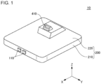
- Fig. 1 is a perspective view of a battery pack 10 according to an embodiment.
- Fig. 2 is a plan view of the battery pack 10 according to the embodiment with an upper case 220 removed.
- Fig. 3 is a plan view of Fig. 2 with a lower bracket 310 and an upper bracket 320 removed.
- Fig. 4 is a view illustrating an A-A cross section in Fig. 2 together with a floor panel 50.
- the battery pack 10 is mounted on an automobile. Specifically, as illustrated in Fig. 4 , the battery pack 10 is mounted below a floor panel 50 between a front wheel and a rear wheel of the automobile. Hereinafter, unless otherwise specified, the battery pack 10 is described as being mounted below the floor panel 50. However, the battery pack 10 is also applicable to a purpose other than an automobile.
- the X direction indicates a front-rear direction of the battery pack 10.
- the Y direction is orthogonal to the X direction.
- the Y direction indicates a left-right direction of the battery pack 10.
- the Z direction is orthogonal to both the X direction and the Y direction.
- the Z direction indicates an upward-downward direction of the battery pack 10.
- the arrow pointing in the X direction, and the arrows pointing in the Y direction and pointing in the Z direction indicate a front direction, a left direction, and an upward direction of the battery pack 10, respectively.
- the white circle with a black dot indicating the Z direction indicates that the arrow pointing to the Z direction extends from the back to the front of the paper.
- the white circle with a black dot indicating the Y direction indicates that the arrow pointing to the Y direction extends from the back to the front of the paper.
- the relationship between the X direction, the Y direction, and the Z direction, and the front-rear direction, the left-right direction, and the upward-downward direction of the battery pack 10 are not limited to this example.
- the front-rear direction, the left-right direction, and the upward-downward direction of the battery pack 10 are determined by the automobile on which the battery pack 10 is mounted.
- the X direction, the Y direction, and the Z direction indicate the front-rear direction, the left-right direction, and the upward-downward direction of the automobile, respectively.
- the arrow pointing in the X direction, the arrow pointing in the Y direction, and the arrow pointing in the Z direction indicate the front direction, the left direction, and the upward direction of the automobile, respectively.
- the relationship between the front-back direction, the left-right direction, and the upward-downward direction of the battery pack 10, and the front-back direction, the left-right direction, and the upward-downward direction of the automobile are not limited to this example.
- a direction perpendicular to the Z direction is referred to as a horizontal direction according to necessity.
- the battery pack 10 includes four battery modules 100, an accommodation body 200, a lower bracket 310, an upper bracket 320, a disconnect switch 410, and a breather 420.
- the four battery modules 100 include a pair of the battery modules 100 on the left side arranged in the X direction and a pair of the battery modules 100 on the right side arranged in the X direction.
- the disconnect switch 410 may also be generally referred to as, for example, a service disconnect switch or a service plug.
- the accommodation body 200 includes a lower case 210 and an upper case 220.
- the lower case 210 may also be generally referred to as, for example, a tray or a main body unit.
- the lower case 210 includes a lower plate 212 and a side frame 214.
- the upper case 220 may also be generally referred to as, for example, a cover or a lid portion.
- Each of the battery modules 100 includes a plurality of battery cells stacked in the horizontal direction.
- a plurality of battery cell groups including a plurality of battery cells connected in parallel are connected in series.
- a plurality of single battery cells may be connected in series.
- a pair of the terminals 110 is provided in front of the side frame 214.
- the pair of the terminals 110 is arranged substantially parallel in the Y direction.
- the front end portion of each of the terminals 110 projects forward from the front surface of the side frame 214.
- the four battery modules 100 are connected in series between a pair of the terminals 110.
- the number and arrangement of the battery modules 100 are not limited to the example according to the embodiment.
- the number of the battery modules 100 may be only two, only three, or five or more.
- the battery pack 10 can include a plurality of battery modules 100.
- the lower case 210 and the upper case 220 are attached to each other via a seal member 230.
- the lower case 210, the upper case 220, and the seal member 230 form an accommodation space 250.
- the accommodation space 250 accommodates the four battery modules 100, the disconnect switch 410, the lower bracket 310, and the upper bracket 320.
- the lower plate 212 defines a bottom portion of the accommodation space 250.
- the side frame 214 defines a side portion of the accommodation space 250. Specifically, the side frame 214 is provided along the outermost circumference of the lower plate 212 when viewed from the Z direction.
- the upper case 220 defines a top portion of the accommodation space 250.
- the seal member 230 is, for example, an elastic material such as rubber.
- the seal member 230 is provided over the entire circumference of the side frame 214 when viewed from the Z direction. Thereby, the seal member 230 surrounds the accommodation space 250 when viewed from the Z direction. Accordingly, the accommodation space 250 can be sealed from a space outside the accommodation body 200 by the seal member 230.
- the lower bracket 310 and the upper bracket 320 overlap in two stages with the accommodation space 250.
- the lower end of the lower case 210 is fixed to the lower plate 212 with a fastener such as an unillustrated bolt.
- the lower case 210 covers at least some of the battery modules 100.
- the lower end of the upper bracket 320 is fixed to the upper surface of the lower bracket 310 by a fastener such as an unillustrated bolt.
- the upper bracket 320 projects upward from the upper surface of the lower bracket 310.
- the disconnect switch 410 has a function of disconnecting a circuit electrically connecting the battery modules 100. Some of the battery modules 100 are electrically connected to each other via the disconnect switch 410. In the embodiment, the circuit electrically connecting the battery modules 100 may be a high voltage circuit. Thus, under a predetermined condition such as maintenance work of the battery pack 10 or emergency stoppage of the battery pack 10, the circuit electrically connecting the battery modules 100 needs to be disconnected to ensure safety of a worker of the battery pack 10. In the embodiment, the circuit connecting the battery modules 100 can be disconnected by operating the disconnect switch 410.
- the disconnect switch 410 is provided at the front portion of the upper end of the upper bracket 320. Accordingly, the disconnect switch 410 can be locally arranged at a high position. In the embodiment, the disconnect switch 410 is oriented diagonally upward. As illustrated in Fig. 1 , the front surface of the disconnect switch 410 is exposed from the upper case 220. Accordingly, the worker of the battery pack 10 can open the lid 52 provided on the floor panel 50 and operate the disconnect switch 410 from the front of the battery pack 10.
- Air inside the accommodation space 250 and air outside the accommodation space 250 are passable through the breather 420.
- the breather 420 has a ventilation membrane for equalizing a difference between pressure inside the accommodation space 250 and pressure outside the accommodation space 250.
- the breather 420 allows air outside the accommodation space 250 to enter inside of the accommodation space 250.
- the breather 420 discharges the air inside the accommodation space 250 to outside of the accommodation space 250.
- the breather 420 can shield foreign matter such as water and dust. Accordingly, the foreign matter such as water and dust can be suppressed from entering from the space outside the accommodation space 250 into the space inside the accommodation space 250.
- the breather 420 is provided at the rear portion of the upper end of the upper bracket 320. Accordingly, the breather 420 can be locally arranged at a high position.
- the disconnect switch 410 and the breather 420 are arranged on opposite sides of the upper bracket 320 to each other in the X direction. Thereby, the breather 420 is arranged on the opposite side of the side of the upper bracket 320 facing the lid 52.
- water flowing from the front of the floor panel 50 can be prevented from being directly injected to the breather 420.
- the lower bracket 310 is provided with at least one electronic component 312.
- two electronic components 312 are arranged on opposite sides of the upper bracket 320 in the Y direction when viewed from above.
- the number and arrangement of the lower brackets 310 are not limited to the example illustrated in Fig. 2 .
- Each of the electronic components 312 controls a plurality of the battery modules 100.
- the electronic component 312 is a battery management system (BMS).
- BMS battery management system
- the electronic component 312 manages and controls charging and discharging of a plurality of the battery modules 100.
Landscapes
- Chemical & Material Sciences (AREA)
- Chemical Kinetics & Catalysis (AREA)
- Electrochemistry (AREA)
- General Chemical & Material Sciences (AREA)
- Engineering & Computer Science (AREA)
- Microelectronics & Electronic Packaging (AREA)
- Manufacturing & Machinery (AREA)
- Battery Mounting, Suspending (AREA)
- Gas Exhaust Devices For Batteries (AREA)
- Connection Of Batteries Or Terminals (AREA)
Abstract
Description
- The present invention relates to a battery pack.
- In recent years, battery packs used for various purposes such as automobiles have been developed. A battery pack includes a plurality of battery modules, an accommodation body in which a plurality of modules is accommodated, and a disconnect switch for disconnecting a circuit electrically connecting the battery modules to each other. The disconnect switch may also be generally referred to as, for example, a service disconnect switch (SD/SW) or a service plug.
- Patent Document 1 describes one example of a battery pack. In the battery pack, a service plug is supported by a support member fixed to an accommodation member.
- Patent Document 2 describes one example of a battery pack. In the battery pack, a middle base is provided above a battery module. An SD/SW and another electronic component are installed on the middle base.
-
- Patent Document 1:
Japanese Patent Application Publication No. 2021-174663 - Patent Document 2: International Patent Publication No.
2013/186878 - In the battery pack described in Patent Document 1, for example, the support member is locally arranged in a region where the service plug is arranged. In this case, however, the area of the support member is relatively small. This may make it difficult to mount a component other than the service plug on the support member. Accordingly, it may be difficult to improve mounting efficiency of a component around the service plug. In the battery pack described in Patent Document 2, for example, the SD/SW and another electronic component are mounted on the middle base. In this case, however, it may be difficult to arrange the SD/SW at a higher position than the another electronic component.
- One example of an object of the present invention is to locally arrange a disconnect switch at a high position while improving mounting efficiency of a component around the disconnect switch. Another object of the present invention will become apparent from description in the present specification.
- An aspect of the present invention is as follows.
- [1] A battery pack including:
- a plurality of battery modules;
- an accommodation body that defines an accommodation space accommodating the plurality of battery modules;
- a plurality of brackets overlapping in a plurality of stages with at least a portion of the accommodation space; and
- a disconnect switch for disconnecting a circuit electrically connecting the battery modules to each other, the disconnect switch being provided to the plurality of brackets.
- [2] The battery pack according to [1], further including
an electronic component provided to at least one of the plurality of brackets, the electronic component being for controlling the plurality of battery modules. - [3] The battery pack according to [1] or [2], further including
- a breather through which air inside the accommodation space and air outside the accommodation space are passable, wherein
- the disconnect switch and the breather are arranged on opposite sides of the plurality of brackets to each other.
- According to the aspect of the present invention described above, the mounting efficiency of a component around the disconnect switch can be improved, and the disconnect switch can be locally arranged at a high position.
-
- [
Fig. 1 ] A perspective view of a battery pack according to an embodiment. - [
Fig. 2 ] A plan view of the battery pack according to the embodiment with an upper case removed. - [
Fig. 3 ] A plan view ofFig. 2 with a lower bracket and an upper bracket removed. - [
Fig. 4 ] A view illustrating an A-A cross section inFig. 2 together with a floor panel. - Hereinafter, an embodiment according to the present invention is described using the drawings. In all the drawings, a similar component is assigned with a similar reference sign, and description thereof is omitted as appropriate.
-
Fig. 1 is a perspective view of abattery pack 10 according to an embodiment.Fig. 2 is a plan view of thebattery pack 10 according to the embodiment with anupper case 220 removed.Fig. 3 is a plan view ofFig. 2 with alower bracket 310 and anupper bracket 320 removed.Fig. 4 is a view illustrating an A-A cross section inFig. 2 together with afloor panel 50. - In the embodiment, the
battery pack 10 is mounted on an automobile. Specifically, as illustrated inFig. 4 , thebattery pack 10 is mounted below afloor panel 50 between a front wheel and a rear wheel of the automobile. Hereinafter, unless otherwise specified, thebattery pack 10 is described as being mounted below thefloor panel 50. However, thebattery pack 10 is also applicable to a purpose other than an automobile. - In each figure, an X direction, a Y direction, and a Z direction are illustrated for description. The X direction indicates a front-rear direction of the
battery pack 10. The Y direction is orthogonal to the X direction. The Y direction indicates a left-right direction of thebattery pack 10. The Z direction is orthogonal to both the X direction and the Y direction. The Z direction indicates an upward-downward direction of thebattery pack 10. The arrow pointing in the X direction, and the arrows pointing in the Y direction and pointing in the Z direction indicate a front direction, a left direction, and an upward direction of thebattery pack 10, respectively. In each ofFigs. 2 and3 , the white circle with a black dot indicating the Z direction indicates that the arrow pointing to the Z direction extends from the back to the front of the paper. InFig. 4 , the white circle with a black dot indicating the Y direction indicates that the arrow pointing to the Y direction extends from the back to the front of the paper. However, the relationship between the X direction, the Y direction, and the Z direction, and the front-rear direction, the left-right direction, and the upward-downward direction of thebattery pack 10 are not limited to this example. - In the embodiment, the front-rear direction, the left-right direction, and the upward-downward direction of the
battery pack 10 are determined by the automobile on which thebattery pack 10 is mounted. The X direction, the Y direction, and the Z direction indicate the front-rear direction, the left-right direction, and the upward-downward direction of the automobile, respectively. The arrow pointing in the X direction, the arrow pointing in the Y direction, and the arrow pointing in the Z direction indicate the front direction, the left direction, and the upward direction of the automobile, respectively. However, the relationship between the front-back direction, the left-right direction, and the upward-downward direction of thebattery pack 10, and the front-back direction, the left-right direction, and the upward-downward direction of the automobile are not limited to this example. - Hereinafter, a direction perpendicular to the Z direction is referred to as a horizontal direction according to necessity.
- The
battery pack 10 includes fourbattery modules 100, anaccommodation body 200, alower bracket 310, anupper bracket 320, adisconnect switch 410, and abreather 420. The fourbattery modules 100 include a pair of thebattery modules 100 on the left side arranged in the X direction and a pair of thebattery modules 100 on the right side arranged in the X direction. Thedisconnect switch 410 may also be generally referred to as, for example, a service disconnect switch or a service plug. Theaccommodation body 200 includes alower case 210 and anupper case 220. Thelower case 210 may also be generally referred to as, for example, a tray or a main body unit. Thelower case 210 includes alower plate 212 and aside frame 214. Theupper case 220 may also be generally referred to as, for example, a cover or a lid portion. - Each of the
battery modules 100 includes a plurality of battery cells stacked in the horizontal direction. In each of thebattery modules 100, for example, a plurality of battery cell groups including a plurality of battery cells connected in parallel are connected in series. Alternatively, a plurality of single battery cells may be connected in series. - A pair of the
terminals 110 is provided in front of theside frame 214. The pair of theterminals 110 is arranged substantially parallel in the Y direction. The front end portion of each of theterminals 110 projects forward from the front surface of theside frame 214. In an electric path, the fourbattery modules 100 are connected in series between a pair of theterminals 110. - The number and arrangement of the
battery modules 100 are not limited to the example according to the embodiment. For example, the number of thebattery modules 100 may be only two, only three, or five or more. In other words, thebattery pack 10 can include a plurality ofbattery modules 100. - The
lower case 210 and theupper case 220 are attached to each other via aseal member 230. Thelower case 210, theupper case 220, and theseal member 230 form anaccommodation space 250. Theaccommodation space 250 accommodates the fourbattery modules 100, thedisconnect switch 410, thelower bracket 310, and theupper bracket 320. - The
lower plate 212 defines a bottom portion of theaccommodation space 250. Theside frame 214 defines a side portion of theaccommodation space 250. Specifically, theside frame 214 is provided along the outermost circumference of thelower plate 212 when viewed from the Z direction. Theupper case 220 defines a top portion of theaccommodation space 250. - The
seal member 230 is, for example, an elastic material such as rubber. Theseal member 230 is provided over the entire circumference of theside frame 214 when viewed from the Z direction. Thereby, theseal member 230 surrounds theaccommodation space 250 when viewed from the Z direction. Accordingly, theaccommodation space 250 can be sealed from a space outside theaccommodation body 200 by theseal member 230. - The
lower bracket 310 and theupper bracket 320 overlap in two stages with theaccommodation space 250. Specifically, the lower end of thelower case 210 is fixed to thelower plate 212 with a fastener such as an unillustrated bolt. Thelower case 210 covers at least some of thebattery modules 100. The lower end of theupper bracket 320 is fixed to the upper surface of thelower bracket 310 by a fastener such as an unillustrated bolt. Theupper bracket 320 projects upward from the upper surface of thelower bracket 310. - The
disconnect switch 410 has a function of disconnecting a circuit electrically connecting thebattery modules 100. Some of thebattery modules 100 are electrically connected to each other via thedisconnect switch 410. In the embodiment, the circuit electrically connecting thebattery modules 100 may be a high voltage circuit. Thus, under a predetermined condition such as maintenance work of thebattery pack 10 or emergency stoppage of thebattery pack 10, the circuit electrically connecting thebattery modules 100 needs to be disconnected to ensure safety of a worker of thebattery pack 10. In the embodiment, the circuit connecting thebattery modules 100 can be disconnected by operating thedisconnect switch 410. - The
disconnect switch 410 is provided at the front portion of the upper end of theupper bracket 320. Accordingly, thedisconnect switch 410 can be locally arranged at a high position. In the embodiment, thedisconnect switch 410 is oriented diagonally upward. As illustrated inFig. 1 , the front surface of thedisconnect switch 410 is exposed from theupper case 220. Accordingly, the worker of thebattery pack 10 can open thelid 52 provided on thefloor panel 50 and operate thedisconnect switch 410 from the front of thebattery pack 10. - Air inside the
accommodation space 250 and air outside theaccommodation space 250 are passable through thebreather 420. Specifically, thebreather 420 has a ventilation membrane for equalizing a difference between pressure inside theaccommodation space 250 and pressure outside theaccommodation space 250. Thus, when the pressure outside theaccommodation space 250 is higher than the pressure inside theaccommodation space 250, thebreather 420 allows air outside theaccommodation space 250 to enter inside of theaccommodation space 250. Contrarily, when the pressure inside theaccommodation space 250 is higher than the pressure outside theaccommodation space 250, thebreather 420 discharges the air inside theaccommodation space 250 to outside of theaccommodation space 250. Thebreather 420 can shield foreign matter such as water and dust. Accordingly, the foreign matter such as water and dust can be suppressed from entering from the space outside theaccommodation space 250 into the space inside theaccommodation space 250. - The
breather 420 is provided at the rear portion of the upper end of theupper bracket 320. Accordingly, thebreather 420 can be locally arranged at a high position. In the embodiment, thedisconnect switch 410 and thebreather 420 are arranged on opposite sides of theupper bracket 320 to each other in the X direction. Thereby, thebreather 420 is arranged on the opposite side of the side of theupper bracket 320 facing thelid 52. Thus, water flowing from the front of thefloor panel 50 can be prevented from being directly injected to thebreather 420. - The
lower bracket 310 is provided with at least oneelectronic component 312. In the example illustrated inFig. 2 , twoelectronic components 312 are arranged on opposite sides of theupper bracket 320 in the Y direction when viewed from above. However, the number and arrangement of thelower brackets 310 are not limited to the example illustrated inFig. 2 . Each of theelectronic components 312 controls a plurality of thebattery modules 100. In the embodiment, theelectronic component 312 is a battery management system (BMS). For example, theelectronic component 312 manages and controls charging and discharging of a plurality of thebattery modules 100. - In the embodiment, each of the
electronic components 312 is provided to thelower bracket 310, which is different from theupper bracket 320 provided with thedisconnect switch 410 and thebreather 420. An area of thelower bracket 310 is larger than an area of theupper bracket 320 when viewed from above. Each of theelectronic components 312 is provided to a portion of thelower bracket 310 that does not overlap with theupper bracket 320 with the Z direction. Accordingly, the mounting efficiency of a component around thedisconnect switch 410 can be improved. - The structure of a plurality of brackets provided with the
disconnect switch 410 and thebreather 420 is not limited to thelower bracket 310 and theupper bracket 320 according to the embodiment. For example, thedisconnect switch 410 and thebreather 420 may be provided to a plurality of three or more brackets that overlap in three stages with theaccommodation space 250. In the example, thedisconnect switch 410 and thebreather 420 can be provided to the uppermost stage bracket. Theelectronic component 312 can be provided to the bracket at a stage lower than the uppermost stage bracket. In this case, theelectronic component 312 can be arranged in a region that does not overlap with the uppermost stage bracket in the Z direction. Thereby, thedisconnect switch 410 and thebreather 420 can be locally arranged at a high position while improving the mounting efficiency of a component around thedisconnect switch 410. - The embodiments according to the present invention have been described above with reference to the drawings, but these are exemplifications of the present invention, and various configurations other than those described above can also be adopted.
- This application claims priority based on
Japanese patent application No. 2022-139692, filed on September 2, 2022 - 10 Battery pack, 50 Floor panel, 52 Lid, 100 Battery module, 110 Terminal, 200 Accommodation body, 210 Lower case, 212 Lower plate, 214 Side frame, 220 Upper case, 230 Seal member, 250 Accommodation space, 310 Lower bracket, 312 Electronic component, 320 Upper bracket, 410 Disconnect switch, 420 Breather
Claims (3)
- A battery pack comprising:a plurality of battery modules;an accommodation body that defines an accommodation space accommodating the plurality of battery modules;a plurality of brackets overlapping in a plurality of stages with at least a portion of the accommodation space; anda disconnect switch for disconnecting a circuit electrically connecting the battery modules to each other, the disconnect switch being provided to the plurality of brackets.
- The battery pack according to claim 1, further comprising
an electronic component provided to at least one of the plurality of brackets, the electronic component being for controlling the plurality of battery modules. - The battery pack according to claim 1 or 2, further comprisinga breather through which air inside the accommodation space and air outside the accommodation space are passable, whereinthe disconnect switch and the breather are arranged on opposite sides of the plurality of brackets to each other.
Applications Claiming Priority (2)
| Application Number | Priority Date | Filing Date | Title |
|---|---|---|---|
| JP2022139692A JP2024035311A (en) | 2022-09-02 | 2022-09-02 | battery pack |
| PCT/JP2023/030279 WO2024048385A1 (en) | 2022-09-02 | 2023-08-23 | Battery pack |
Publications (2)
| Publication Number | Publication Date |
|---|---|
| EP4583302A1 true EP4583302A1 (en) | 2025-07-09 |
| EP4583302A4 EP4583302A4 (en) | 2026-02-18 |
Family
ID=90099479
Family Applications (1)
| Application Number | Title | Priority Date | Filing Date |
|---|---|---|---|
| EP23860148.8A Pending EP4583302A4 (en) | 2022-09-02 | 2023-08-23 | BATTERY PACK |
Country Status (5)
| Country | Link |
|---|---|
| US (1) | US20260066366A1 (en) |
| EP (1) | EP4583302A4 (en) |
| JP (1) | JP2024035311A (en) |
| CN (1) | CN119768967A (en) |
| WO (1) | WO2024048385A1 (en) |
Family Cites Families (20)
| Publication number | Priority date | Publication date | Assignee | Title |
|---|---|---|---|---|
| JP3350189B2 (en) * | 1993-04-30 | 2002-11-25 | 本田技研工業株式会社 | Battery box device for electric vehicles |
| MY160128A (en) * | 2009-02-24 | 2017-02-28 | Nissan Motor | Battery mounting structure |
| JP5617200B2 (en) * | 2009-07-17 | 2014-11-05 | 日産自動車株式会社 | battery pack |
| JP5656071B2 (en) * | 2010-12-28 | 2015-01-21 | スズキ株式会社 | Electric vehicle |
| JP5689371B2 (en) * | 2011-06-08 | 2015-03-25 | スズキ株式会社 | Battery pack and power shutoff device |
| WO2013084942A1 (en) * | 2011-12-09 | 2013-06-13 | 本田技研工業株式会社 | Battery pack for electric car |
| JP5879436B2 (en) * | 2012-06-13 | 2016-03-08 | 日立オートモティブシステムズ株式会社 | In-vehicle power storage device |
| US9251985B2 (en) * | 2013-08-08 | 2016-02-02 | Lg Chem, Ltd. | Fuse lock-out assembly for a battery pack |
| US9577230B2 (en) * | 2014-03-27 | 2017-02-21 | Ford Global Technologies, Llc | Integrated high voltage service disconnect for traction batteries |
| JP6476916B2 (en) * | 2015-01-27 | 2019-03-06 | 日産自動車株式会社 | Assembled battery |
| JP2019169414A (en) * | 2018-03-26 | 2019-10-03 | 三菱自動車工業株式会社 | Vehicle battery pack |
| JP7055687B2 (en) * | 2018-04-10 | 2022-04-18 | マレリ株式会社 | Batteries assembled |
| CN208507773U (en) * | 2018-07-11 | 2019-02-15 | 华霆(合肥)动力技术有限公司 | Battery modules system and electric vehicle |
| CN208622888U (en) * | 2018-08-22 | 2019-03-19 | 桑顿新能源科技有限公司 | A kind of battery pack MSD mounting assembly |
| JP7020370B2 (en) * | 2018-10-30 | 2022-02-16 | トヨタ自動車株式会社 | Battery pack |
| JP7276683B2 (en) * | 2019-04-24 | 2023-05-18 | マツダ株式会社 | Vehicle battery system |
| JP7494550B2 (en) | 2020-04-24 | 2024-06-04 | マツダ株式会社 | Service plug and vehicle structure of electric vehicle |
| CN115461239B (en) * | 2020-04-28 | 2026-03-10 | 日产自动车株式会社 | Disconnecting plug structure of electric automobile |
| CN115668657B (en) * | 2020-05-29 | 2026-04-28 | 日产自动车株式会社 | Terminal block |
| JP2022139692A (en) | 2021-03-12 | 2022-09-26 | オムロン株式会社 | distance sensor |
-
2022
- 2022-09-02 JP JP2022139692A patent/JP2024035311A/en active Pending
-
2023
- 2023-08-23 EP EP23860148.8A patent/EP4583302A4/en active Pending
- 2023-08-23 US US19/105,436 patent/US20260066366A1/en active Pending
- 2023-08-23 WO PCT/JP2023/030279 patent/WO2024048385A1/en not_active Ceased
- 2023-08-23 CN CN202380061161.9A patent/CN119768967A/en active Pending
Also Published As
| Publication number | Publication date |
|---|---|
| JP2024035311A (en) | 2024-03-14 |
| CN119768967A (en) | 2025-04-04 |
| EP4583302A4 (en) | 2026-02-18 |
| WO2024048385A1 (en) | 2024-03-07 |
| US20260066366A1 (en) | 2026-03-05 |
Similar Documents
| Publication | Publication Date | Title |
|---|---|---|
| US9077019B2 (en) | Electricity storage device and vehicle | |
| US8251169B2 (en) | Temperature adjustment structure for power storage apparatus | |
| EP2454771B1 (en) | Battery pack | |
| JP5879436B2 (en) | In-vehicle power storage device | |
| US20140374180A1 (en) | Structure for mounting battery pack on vehicle | |
| US10220723B2 (en) | Fuel cell vehicle | |
| JP2012119324A (en) | Battery box of railway vehicle and railway vehicle | |
| US11548362B2 (en) | Vehicle battery unit | |
| CN112886121B (en) | Battery system of vehicle | |
| US20200365851A1 (en) | Vehicle battery unit | |
| CN110182262B (en) | Vehicle lower structure | |
| KR102466683B1 (en) | Mounting structure for power storage device | |
| US7508164B2 (en) | Battery pack having control devices of differing heights | |
| US20260066366A1 (en) | Battery pack | |
| US11646436B2 (en) | Fuel cell system | |
| US12315905B2 (en) | Battery pack and vehicle | |
| CN117525718A (en) | Battery packs and vehicles | |
| US12603370B2 (en) | Traction battery and vehicle having a traction battery | |
| CN117559054A (en) | Battery packs and vehicles | |
| US12431522B2 (en) | Fuel cell system | |
| US11688876B2 (en) | Fuel cell system | |
| JP2016192336A (en) | Power storage device | |
| EP4618280A1 (en) | Battery pack and removal method for battery module | |
| US20240178483A1 (en) | Power Storage Device and Vehicle | |
| US20220293994A1 (en) | Stack case and method of assembling stack case |
Legal Events
| Date | Code | Title | Description |
|---|---|---|---|
| STAA | Information on the status of an ep patent application or granted ep patent |
Free format text: STATUS: THE INTERNATIONAL PUBLICATION HAS BEEN MADE |
|
| PUAI | Public reference made under article 153(3) epc to a published international application that has entered the european phase |
Free format text: ORIGINAL CODE: 0009012 |
|
| STAA | Information on the status of an ep patent application or granted ep patent |
Free format text: STATUS: REQUEST FOR EXAMINATION WAS MADE |
|
| 17P | Request for examination filed |
Effective date: 20250228 |
|
| AK | Designated contracting states |
Kind code of ref document: A1 Designated state(s): AL AT BE BG CH CY CZ DE DK EE ES FI FR GB GR HR HU IE IS IT LI LT LU LV MC ME MK MT NL NO PL PT RO RS SE SI SK SM TR |
|
| DAV | Request for validation of the european patent (deleted) | ||
| DAX | Request for extension of the european patent (deleted) | ||
| A4 | Supplementary search report drawn up and despatched |
Effective date: 20260119 |
|
| RIC1 | Information provided on ipc code assigned before grant |
Ipc: H01M 50/574 20210101AFI20260113BHEP Ipc: H01M 50/204 20210101ALI20260113BHEP Ipc: H01M 50/317 20210101ALI20260113BHEP |