EP4583296A1 - Zellenkontaktfolien, zellenkontaktsysteme und batteriepacks - Google Patents
Zellenkontaktfolien, zellenkontaktsysteme und batteriepacks Download PDFInfo
- Publication number
- EP4583296A1 EP4583296A1 EP24220032.7A EP24220032A EP4583296A1 EP 4583296 A1 EP4583296 A1 EP 4583296A1 EP 24220032 A EP24220032 A EP 24220032A EP 4583296 A1 EP4583296 A1 EP 4583296A1
- Authority
- EP
- European Patent Office
- Prior art keywords
- cells contact
- sheet
- sheets
- cells
- acquisition
- Prior art date
- Legal status (The legal status is an assumption and is not a legal conclusion. Google has not performed a legal analysis and makes no representation as to the accuracy of the status listed.)
- Pending
Links
Images




Classifications
-
- H—ELECTRICITY
- H01—ELECTRIC ELEMENTS
- H01M—PROCESSES OR MEANS, e.g. BATTERIES, FOR THE DIRECT CONVERSION OF CHEMICAL ENERGY INTO ELECTRICAL ENERGY
- H01M10/00—Secondary cells; Manufacture thereof
- H01M10/42—Methods or arrangements for servicing or maintenance of secondary cells or secondary half-cells
- H01M10/425—Structural combination with electronic components, e.g. electronic circuits integrated to the outside of the casing
-
- H—ELECTRICITY
- H01—ELECTRIC ELEMENTS
- H01M—PROCESSES OR MEANS, e.g. BATTERIES, FOR THE DIRECT CONVERSION OF CHEMICAL ENERGY INTO ELECTRICAL ENERGY
- H01M10/00—Secondary cells; Manufacture thereof
- H01M10/42—Methods or arrangements for servicing or maintenance of secondary cells or secondary half-cells
- H01M10/48—Accumulators combined with arrangements for measuring, testing or indicating the condition of cells, e.g. the level or density of the electrolyte
- H01M10/482—Accumulators combined with arrangements for measuring, testing or indicating the condition of cells, e.g. the level or density of the electrolyte for several batteries or cells simultaneously or sequentially
-
- H—ELECTRICITY
- H01—ELECTRIC ELEMENTS
- H01M—PROCESSES OR MEANS, e.g. BATTERIES, FOR THE DIRECT CONVERSION OF CHEMICAL ENERGY INTO ELECTRICAL ENERGY
- H01M10/00—Secondary cells; Manufacture thereof
- H01M10/42—Methods or arrangements for servicing or maintenance of secondary cells or secondary half-cells
- H01M10/48—Accumulators combined with arrangements for measuring, testing or indicating the condition of cells, e.g. the level or density of the electrolyte
- H01M10/486—Accumulators combined with arrangements for measuring, testing or indicating the condition of cells, e.g. the level or density of the electrolyte for measuring temperature
-
- H—ELECTRICITY
- H01—ELECTRIC ELEMENTS
- H01M—PROCESSES OR MEANS, e.g. BATTERIES, FOR THE DIRECT CONVERSION OF CHEMICAL ENERGY INTO ELECTRICAL ENERGY
- H01M50/00—Constructional details or processes of manufacture of the non-active parts of electrochemical cells other than fuel cells, e.g. hybrid cells
- H01M50/20—Mountings; Secondary casings or frames; Racks, modules or packs; Suspension devices; Shock absorbers; Transport or carrying devices; Holders
- H01M50/204—Racks, modules or packs for multiple batteries or multiple cells
-
- H—ELECTRICITY
- H01—ELECTRIC ELEMENTS
- H01M—PROCESSES OR MEANS, e.g. BATTERIES, FOR THE DIRECT CONVERSION OF CHEMICAL ENERGY INTO ELECTRICAL ENERGY
- H01M50/00—Constructional details or processes of manufacture of the non-active parts of electrochemical cells other than fuel cells, e.g. hybrid cells
- H01M50/20—Mountings; Secondary casings or frames; Racks, modules or packs; Suspension devices; Shock absorbers; Transport or carrying devices; Holders
- H01M50/204—Racks, modules or packs for multiple batteries or multiple cells
- H01M50/207—Racks, modules or packs for multiple batteries or multiple cells characterised by their shape
- H01M50/209—Racks, modules or packs for multiple batteries or multiple cells characterised by their shape adapted for prismatic or rectangular cells
-
- H—ELECTRICITY
- H01—ELECTRIC ELEMENTS
- H01M—PROCESSES OR MEANS, e.g. BATTERIES, FOR THE DIRECT CONVERSION OF CHEMICAL ENERGY INTO ELECTRICAL ENERGY
- H01M50/00—Constructional details or processes of manufacture of the non-active parts of electrochemical cells other than fuel cells, e.g. hybrid cells
- H01M50/20—Mountings; Secondary casings or frames; Racks, modules or packs; Suspension devices; Shock absorbers; Transport or carrying devices; Holders
- H01M50/258—Modular batteries; Casings provided with means for assembling
-
- H—ELECTRICITY
- H01—ELECTRIC ELEMENTS
- H01M—PROCESSES OR MEANS, e.g. BATTERIES, FOR THE DIRECT CONVERSION OF CHEMICAL ENERGY INTO ELECTRICAL ENERGY
- H01M50/00—Constructional details or processes of manufacture of the non-active parts of electrochemical cells other than fuel cells, e.g. hybrid cells
- H01M50/20—Mountings; Secondary casings or frames; Racks, modules or packs; Suspension devices; Shock absorbers; Transport or carrying devices; Holders
- H01M50/284—Mountings; Secondary casings or frames; Racks, modules or packs; Suspension devices; Shock absorbers; Transport or carrying devices; Holders with incorporated circuit boards, e.g. printed circuit boards [PCB]
-
- H—ELECTRICITY
- H01—ELECTRIC ELEMENTS
- H01M—PROCESSES OR MEANS, e.g. BATTERIES, FOR THE DIRECT CONVERSION OF CHEMICAL ENERGY INTO ELECTRICAL ENERGY
- H01M50/00—Constructional details or processes of manufacture of the non-active parts of electrochemical cells other than fuel cells, e.g. hybrid cells
- H01M50/50—Current conducting connections for cells or batteries
- H01M50/502—Interconnectors for connecting terminals of adjacent batteries; Interconnectors for connecting cells outside a battery casing
- H01M50/503—Interconnectors for connecting terminals of adjacent batteries; Interconnectors for connecting cells outside a battery casing characterised by the shape of the interconnectors
-
- H—ELECTRICITY
- H01—ELECTRIC ELEMENTS
- H01M—PROCESSES OR MEANS, e.g. BATTERIES, FOR THE DIRECT CONVERSION OF CHEMICAL ENERGY INTO ELECTRICAL ENERGY
- H01M50/00—Constructional details or processes of manufacture of the non-active parts of electrochemical cells other than fuel cells, e.g. hybrid cells
- H01M50/50—Current conducting connections for cells or batteries
- H01M50/502—Interconnectors for connecting terminals of adjacent batteries; Interconnectors for connecting cells outside a battery casing
- H01M50/507—Interconnectors for connecting terminals of adjacent batteries; Interconnectors for connecting cells outside a battery casing comprising an arrangement of two or more busbars within a container structure, e.g. busbar modules
-
- H—ELECTRICITY
- H01—ELECTRIC ELEMENTS
- H01M—PROCESSES OR MEANS, e.g. BATTERIES, FOR THE DIRECT CONVERSION OF CHEMICAL ENERGY INTO ELECTRICAL ENERGY
- H01M10/00—Secondary cells; Manufacture thereof
- H01M10/42—Methods or arrangements for servicing or maintenance of secondary cells or secondary half-cells
- H01M10/425—Structural combination with electronic components, e.g. electronic circuits integrated to the outside of the casing
- H01M2010/4271—Battery management systems including electronic circuits, e.g. control of current or voltage to keep battery in healthy state, cell balancing
-
- H—ELECTRICITY
- H01—ELECTRIC ELEMENTS
- H01M—PROCESSES OR MEANS, e.g. BATTERIES, FOR THE DIRECT CONVERSION OF CHEMICAL ENERGY INTO ELECTRICAL ENERGY
- H01M2220/00—Batteries for particular applications
- H01M2220/20—Batteries in motive systems, e.g. vehicle, ship, plane
-
- Y—GENERAL TAGGING OF NEW TECHNOLOGICAL DEVELOPMENTS; GENERAL TAGGING OF CROSS-SECTIONAL TECHNOLOGIES SPANNING OVER SEVERAL SECTIONS OF THE IPC; TECHNICAL SUBJECTS COVERED BY FORMER USPC CROSS-REFERENCE ART COLLECTIONS [XRACs] AND DIGESTS
- Y02—TECHNOLOGIES OR APPLICATIONS FOR MITIGATION OR ADAPTATION AGAINST CLIMATE CHANGE
- Y02E—REDUCTION OF GREENHOUSE GAS [GHG] EMISSIONS, RELATED TO ENERGY GENERATION, TRANSMISSION OR DISTRIBUTION
- Y02E60/00—Enabling technologies; Technologies with a potential or indirect contribution to GHG emissions mitigation
- Y02E60/10—Energy storage using batteries
Definitions
- a cells contact sheet is usually used to acquire the temperature signals and voltage signals of the multiple cell groups.
- a cell may expand due to rising temperature and thus produce tension on the cells contact sheet welded to the cell, so that the weld between the cells contact sheet and the cell may be broken and even the cells contact sheet may be torn. Therefore, the reliability of the acquisition result may be reduced.
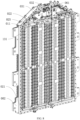
- a battery pack includes a housing, a battery module, a BMS board, and at least one of aforementioned cells contact system.
- the housing is provided with a first accommodating cavity and a second accommodating cavity arranged in a longitudinal direction; the battery module is arranged in the first accommodating cavity and includes multiple cell groups arranged in the longitudinal direction; the BMS board is arranged in the second accommodating cavity; and one of the cells contact sub-sheets is provided with a first signal output terminal connected to the BMS board.
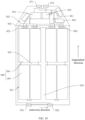
- FIG. 1 schematically shows a structure of a cells contact sheet 011 applicable to a battery module according to one or more embodiments of the present application.
- the battery module includes two cell groups.
- the cells contact sheet 011 includes two cells contact sub-sheets 111 and a flexible conductive connecting sheet 112.
- the two cells contact sub-sheets 111 are arranged successively in parallel.
- the two cells contact sub-sheets 111 are configured respectively to acquire work signals of the two cell groups.
- the connecting sheet 112 is arranged between the two cells contact sub-sheets 111.
- the two ends of the connecting sheet 112 are respectively connected with the two cells contact sub-sheets 111, and the connecting sheet 112 is provided with a first bending structure 1121, which is configured to deform when the two cell groups move away from or close to each other.
- the first bending structure 1121 when the two cell groups move away from each other or close to each other, the first bending structure 1121 will undergo flexible deformation due to the flexibility of the connecting sheet 112.
- the connecting sheet 112 is an elastic metal sheet
- the first bending structure 1121 also has an elastic deformation.
- the work signals are mainly voltage signals of the cells and temperature signals of the cell groups.
- the cells contact sheet is provided with a buffer part formed based on the first bending structure 1121, in this way, when the cell groups produce thermal expansion, the buffer part can be deformed to buffer the expansion between the cell groups to pull the cells contact sheet 011, and then improve the stability of the welding part between the cells contact sheet 11 and the cells, and avoid the cells contact sheet 011 being torn, and finally improve the reliability of the cells contact sheet 011.
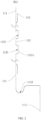
- FIG. 2 shows the side view of the cells contact sheet 011 according to one or more embodiments of the present application.
- the connecting sheet 112 includes a sheet body and a first bending structure 1121, and the first bending structure 1121 is convex to the cell groups from the location of the sheet body of the connecting sheet 112.
- the first bending structure 1121 is convex towards the cell group from the location of the sheet body of the connecting sheet 112, so that the cells contact sheet 011 can have a structure for buffering the pulling or squeezing of the cells contact sheet 011, and the first bending structure 1121 is overlapped with the busbar 131 on the axis of the cells, thus, avoiding the arranging of the first bending structure 1121 increases the height of the cells contact system 001, which is conducive to the layout of the electrical parts inside the battery pack.
- the first bending structure 1121 shown in FIG. 2 has a first surface 11211 located in the middle of the first bending structure 1121 and toward the cell groups.
- the first surface 11211 is parallel to the cells contact sub-sheet 111.
- the first bending structure 1121 is a U-shaped structure convex to the cell groups, where the side of the part facing the cell groups is the first surface 11211.
- the connecting sheet 112 includes two extension segments and a first bending structure 1121 located between the two extension segments.
- the two extension segments are respectively connected with two cells contact sub-sheets 111.
- the first bending structure 1121 includes a first bending segment, a second bending segment and a third bending segment successively connected.
- the first bending segment and the third bending segment are arranged relative to each other.
- the ends of the first bending segment and the third bending segment deviated from the second bending segment are connected to the two extension segments respectively.
- the first surface 11211 is on the side of the second bending segment facing the cell group.
- the first bending structure 1121 has a longer length in a certain space, so that the first bending structure 1121 has a larger buffer size, and then the first bending structure 1121 can achieve a better buffer effect in a limited space.
- the first signal output terminal 1111 is connected to the BMS board.
- the first signal output terminal 1111 is connected with the BMS board via a connector 063 to transmit the acquired work signals to the BMS board.
- the cells contact sub-sheet 111 closer to the BMS board is the output cells contact sub-sheet 111
- the end of the output cells contact sub-sheet 111 near the BMS board is the first signal output terminal 1111.
- the first signal output terminal 1111 Since the first signal output terminal 1111 is connected to the BMS board, the first signal output terminal 1111 is fixed. When the cells generate thermal expansion, it will pull on the joint between the first signal output terminal 1111 and the BMS board. Based on this, in the present embodiment, a second bending structure 1112 is provided at one end of the output cells contact sub-sheet 111 near the first signal output terminal 1111, so that the end of the output cells contact sub-sheet 111 near the first signal output terminal 1111 is provided with a structure for buffering the pulling of the first signal output terminal 1111 when the cell groups expand. Thus, the reliability of the connection between the cells contact sheet 011 and the BMS board is improved, and the cells contact sheet 011 is prevented from being torn.
- the second bending structure 1112 shown in FIG. 2 is an arc structure with concave surface away from the first signal output terminal 1111.
- the side of the second bending structure 1112 away from the first signal output terminal 1111 is tangent to the side of the cells contact sub-sheet 111 located at the second bending structure 1112 away from the first signal output terminal 1111.
- the stress of the second bending structure 1112 can be reduced, thereby improving the impact resistance of the cells contact sheet 011 and thereby improving the reliability of the cells contact sheet 011.
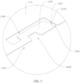
- FIG. 3 is an enlarged view of part A in FIG. 1 .
- the cells contact sub-sheet 111 has a voltage acquisition area 1113.
- the voltage acquisition area 1113 is provided with an acquisition notch 1114.
- An acquisition terminal sheet 1115 which is configured to acquire the voltage of the cell group is provided in the acquisition notch 1114.
- the acquisition terminal sheet 1115 has a first end and a second end opposite to each other, and the first end is connected with one surface of the acquisition notch 1114.
- the second end is connected with another surface of the acquisition notch 114. From the first end to the second end, there is a gap 1116 between the acquisition terminal sheet 1115 and the acquisition notch 1114.
- the cells contact sub-sheet 111 can acquire the voltage information of the cells; on the other hand, when the cells expands, the pulling force on the acquisition terminal sheet 1115 is mainly applicable to the first and second ends of the acquisition terminal sheet 1115, thus reducing the pulling force borne by the acquisition terminal sheet 1115, and then avoiding the weld between the acquisition terminal sheet 1115 and the busbar 131 falling off.
- the stability of the connection between the acquisition terminal sheet 1115 and the busbar 131 can be improved.
- connection structure by connecting the second end of the acquisition terminal sheet 1115 with the surface of the acquisition notch 1114 through the connection structure, when the acquisition terminal sheet 1115 bearing relatively large pulling force, the connection structure at one end of the acquisition terminal sheet 1115 can be disconnected through the pulling force to reduce the pulling force borne by the acquisition terminal sheet 1115.
- the weld between the acquisition terminal sheet 1115 and busbar 131 can be avoided from falling off, and the stability of the connection between the acquisition terminal sheet 1115 and busbar 131 can be improved.
- connection structure may adopt a structure thinner than the acquisition terminal sheet 1115, or a material with lower strength than the joint between the first end of the acquisition terminal sheet 1115 and the acquisition notch 1114.
- the connection structure includes a connection strip 1117.
- the two ends of the connection strip 1117 are respectively connected with the second end of the acquisition terminal sheet 1115 and a surface of the acquisition notch 1114.
- the middle part of the connection strip 1117 is provided with a cutting notch 11171.
- the cutting notch 11171 is configured to cause the connection strip 1117 to break when the cells contact sub-sheet 111 is pulled.
- the acquisition terminal sheet 1115 shown in FIG. 3 is provided with a buffer notch 11151.
- the buffer notch 11151 is arranged between the first end of the acquisition terminal sheet 1115 and the second end of the acquisition terminal sheet 1115.
- the stress of the acquisition terminal sheet 1115 during thermal expansion can be alleviated by arranging the buffer notch 11151, thereby improving the stability of the connection between the acquisition terminal sheet 1115 and the busbar 131.
- the edge of the cells contact sub-sheet 111 shown in FIG. 1 is connected with a bent terminal sheet 113 configured to acquire the temperature of the cell group.
- the deformability of the bent terminal sheet 113 can be used to buffer the pulling of the cells contact sheet 011 by the thermal expansion of the cells, thereby improving the load bearing capacity of the cells contact sheet 011, and thereby preventing the cells contact sheet 011 from being torn or the disconnection between the bent terminal sheet 113 and the cells contact sub-sheet 111.
- the reliability of the cells contact sheet 011 can be improved.
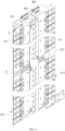
- FIG. 4 schematically shows the structure of the cells contact system 001 according to one or more embodiments of the present application.
- a cells contact system 001 is provided in embodiments of the present application.
- the cells contact system 001 includes a holder 012, busbar groups 013 and the aforementioned cells contact sheet 011.
- the busbar groups 013 include two busbar groups 013.
- the two busbar groups 013 are arranged successively on the holder 012.
- the two busbar groups 013 are configured to respectively connect with the two cell groups.
- Two cells contact sub-sheets 111 are connected to the two busbar groups 013 respectively.
- the connecting sheet 112 is located between the two adjacent busbar groups 013.
- first bending structures 1121 there are two first bending structures 1121 arranged at intervals along the arranging direction of the two cells contact sub-sheets 111.
- the first bending structure 1121 is convex from the position of the sheet body of the connecting sheet 112 towards the cell groups.
- the cells contact sub-sheet 111 is arranged on the holder 012.
- Groove 121 is provided on the holder 012.
- the two first bending structures 1121 are located in the two grooves 121 respectively, as shown in FIG. 5 , which is an enlarged view of part B in FIG. 4 .
- the first bending structure 1121 is fitted with gap 1116 of the groove 121.
- the gap 1116 between the first bending structure 1121 and the groove 121 is used to provide deformation space for a first bend of the first bending structure 1121, so that the deformation of the first bend of first bending structure 1121 is not hindered.
- the concave surface of the second bending structure 1112 faces the end face of the holder 012, as shown in FIF. 6, which is an enlarged view of part C in FIG. 4 .
- Two busbars 131 are connected with two cell groups 081 respectively.
- the two cells contact sub-sheets 111 one is the output cells contact sub-sheet 111.
- the first signal output terminal 1111 of the output cells contact sub-sheet 111 is connected to the BMS board. Specifically, the first signal output terminal 1111 is connected to the BMS board via connector 063.
Landscapes
- Chemical & Material Sciences (AREA)
- Chemical Kinetics & Catalysis (AREA)
- Electrochemistry (AREA)
- General Chemical & Material Sciences (AREA)
- Engineering & Computer Science (AREA)
- Manufacturing & Machinery (AREA)
- Microelectronics & Electronic Packaging (AREA)
- Battery Mounting, Suspending (AREA)
- Secondary Cells (AREA)
- Connection Of Batteries Or Terminals (AREA)
Applications Claiming Priority (2)
| Application Number | Priority Date | Filing Date | Title |
|---|---|---|---|
| CN202323671458.3U CN222126930U (zh) | 2023-12-31 | 2023-12-31 | 采集片、采集组件及电池包 |
| PCT/CN2024/084037 WO2025138468A1 (zh) | 2023-12-31 | 2024-03-27 | 采集片、采集组件及电池包 |
Publications (1)
| Publication Number | Publication Date |
|---|---|
| EP4583296A1 true EP4583296A1 (de) | 2025-07-09 |
Family
ID=93924445
Family Applications (1)
| Application Number | Title | Priority Date | Filing Date |
|---|---|---|---|
| EP24220032.7A Pending EP4583296A1 (de) | 2023-12-31 | 2024-12-16 | Zellenkontaktfolien, zellenkontaktsysteme und batteriepacks |
Country Status (3)
| Country | Link |
|---|---|
| US (1) | US20250219167A1 (de) |
| EP (1) | EP4583296A1 (de) |
| DE (1) | DE202024107163U1 (de) |
Citations (4)
| Publication number | Priority date | Publication date | Assignee | Title |
|---|---|---|---|---|
| US20120328920A1 (en) * | 2010-03-12 | 2012-12-27 | Autonetworks Technologies, Ltd. | Battery module |
| DE102019134469A1 (de) * | 2018-12-29 | 2020-07-02 | Molex, Llc | Batterie-Anschlussmodul |
| US20220255141A1 (en) * | 2021-02-09 | 2022-08-11 | Molex, Llc | Battery connection module |
| EP4195371A2 (de) * | 2021-12-13 | 2023-06-14 | Hyundai Motor Company | Batteriepack für ein fahrzeug |
-
2024
- 2024-12-10 DE DE202024107163.8U patent/DE202024107163U1/de active Active
- 2024-12-16 EP EP24220032.7A patent/EP4583296A1/de active Pending
- 2024-12-22 US US18/991,644 patent/US20250219167A1/en active Pending
Patent Citations (4)
| Publication number | Priority date | Publication date | Assignee | Title |
|---|---|---|---|---|
| US20120328920A1 (en) * | 2010-03-12 | 2012-12-27 | Autonetworks Technologies, Ltd. | Battery module |
| DE102019134469A1 (de) * | 2018-12-29 | 2020-07-02 | Molex, Llc | Batterie-Anschlussmodul |
| US20220255141A1 (en) * | 2021-02-09 | 2022-08-11 | Molex, Llc | Battery connection module |
| EP4195371A2 (de) * | 2021-12-13 | 2023-06-14 | Hyundai Motor Company | Batteriepack für ein fahrzeug |
Also Published As
| Publication number | Publication date |
|---|---|
| US20250219167A1 (en) | 2025-07-03 |
| DE202024107163U1 (de) | 2024-12-23 |
Similar Documents
| Publication | Publication Date | Title |
|---|---|---|
| KR102595362B1 (ko) | 배터리 팩 및 차량 | |
| US12148900B2 (en) | Sampling component, battery module, battery pack, and device | |
| CN112470335B (zh) | 电池模块和包括该电池模块的电池组 | |
| EP3907818A1 (de) | Batteriepack mit beweglicher sammelschienenanordnung und sekundärbatterie damit | |
| WO2020171629A1 (ko) | 유동 너트를 구비한 단자 연결구조를 갖는 전지 모듈과 이를 포함한 전지 팩 | |
| WO2019151716A1 (ko) | 배터리 모듈, 이를 포함하는 배터리 팩 및 자동차 | |
| EP4064417B1 (de) | Batteriemodul mit vereinfachter verbindung zwischen elektrodenleitung und spannungssensorelement sowie ein batteriesatz damit | |
| EP4071888B1 (de) | Batteriemodul mit vereinfachter verbindung zwischen elektrodenleitung und spannungsmesselement sowie batteriepack damit | |
| WO2020171627A1 (ko) | 연성 인쇄 회로 기판을 덮는 보호 커버를 포함하는 전지 모듈 | |
| US12113241B2 (en) | Battery module | |
| CN222126930U (zh) | 采集片、采集组件及电池包 | |
| EP4583296A1 (de) | Zellenkontaktfolien, zellenkontaktsysteme und batteriepacks | |
| CN218101500U (zh) | 电池模组结构 | |
| EP3926745B1 (de) | Batteriemodul | |
| CN115911720A (zh) | 电池包及车辆 | |
| US20240304933A1 (en) | Battery module | |
| CN223427702U (zh) | 电池装置及用电装置 | |
| CN223598965U (zh) | 一种电池包及用电设备 | |
| EP4687191A1 (de) | Erfassungsanordnung, batteriemodul und batteriekasten | |
| US20250141056A1 (en) | Battery module and manufacturing method thereof, battery pack, and electric device | |
| US20260024929A1 (en) | Multilayered flexible flat cable and manufacturing method thereof | |
| CN221057625U (zh) | 采样结构、电池模组及电池包 | |
| CN121035536B (zh) | 电池装置和用电装置 | |
| CN217656026U (zh) | 电池包和动力装置 | |
| CN218827708U (zh) | Ffc采集装置、汇流排组合装置、电池模组和电池包 |
Legal Events
| Date | Code | Title | Description |
|---|---|---|---|
| PUAI | Public reference made under article 153(3) epc to a published international application that has entered the european phase |
Free format text: ORIGINAL CODE: 0009012 |
|
| STAA | Information on the status of an ep patent application or granted ep patent |
Free format text: STATUS: REQUEST FOR EXAMINATION WAS MADE |
|
| 17P | Request for examination filed |
Effective date: 20241216 |
|
| AK | Designated contracting states |
Kind code of ref document: A1 Designated state(s): AL AT BE BG CH CY CZ DE DK EE ES FI FR GB GR HR HU IE IS IT LI LT LU LV MC ME MK MT NL NO PL PT RO RS SE SI SK SM TR |
|
| GRAP | Despatch of communication of intention to grant a patent |
Free format text: ORIGINAL CODE: EPIDOSNIGR1 |
|
| STAA | Information on the status of an ep patent application or granted ep patent |
Free format text: STATUS: GRANT OF PATENT IS INTENDED |
|
| INTG | Intention to grant announced |
Effective date: 20260126 |
|
| GRAS | Grant fee paid |
Free format text: ORIGINAL CODE: EPIDOSNIGR3 |
|
| GRAA | (expected) grant |
Free format text: ORIGINAL CODE: 0009210 |
|
| STAA | Information on the status of an ep patent application or granted ep patent |
Free format text: STATUS: THE PATENT HAS BEEN GRANTED |