EP4583215A1 - Battery and electronic apparatus - Google Patents
Battery and electronic apparatus Download PDFInfo
- Publication number
- EP4583215A1 EP4583215A1 EP23887713.8A EP23887713A EP4583215A1 EP 4583215 A1 EP4583215 A1 EP 4583215A1 EP 23887713 A EP23887713 A EP 23887713A EP 4583215 A1 EP4583215 A1 EP 4583215A1
- Authority
- EP
- European Patent Office
- Prior art keywords
- housing
- pole
- battery
- cell
- conductive member
- Prior art date
- Legal status (The legal status is an assumption and is not a legal conclusion. Google has not performed a legal analysis and makes no representation as to the accuracy of the status listed.)
- Pending
Links
Images


Classifications
-
- H—ELECTRICITY
- H01—ELECTRIC ELEMENTS
- H01M—PROCESSES OR MEANS, e.g. BATTERIES, FOR THE DIRECT CONVERSION OF CHEMICAL ENERGY INTO ELECTRICAL ENERGY
- H01M10/00—Secondary cells; Manufacture thereof
- H01M10/04—Construction or manufacture in general
- H01M10/0436—Small-sized flat cells or batteries for portable equipment
-
- H—ELECTRICITY
- H01—ELECTRIC ELEMENTS
- H01M—PROCESSES OR MEANS, e.g. BATTERIES, FOR THE DIRECT CONVERSION OF CHEMICAL ENERGY INTO ELECTRICAL ENERGY
- H01M50/00—Constructional details or processes of manufacture of the non-active parts of electrochemical cells other than fuel cells, e.g. hybrid cells
- H01M50/10—Primary casings; Jackets or wrappings
- H01M50/102—Primary casings; Jackets or wrappings characterised by their shape or physical structure
- H01M50/103—Primary casings; Jackets or wrappings characterised by their shape or physical structure prismatic or rectangular
-
- H—ELECTRICITY
- H01—ELECTRIC ELEMENTS
- H01M—PROCESSES OR MEANS, e.g. BATTERIES, FOR THE DIRECT CONVERSION OF CHEMICAL ENERGY INTO ELECTRICAL ENERGY
- H01M50/00—Constructional details or processes of manufacture of the non-active parts of electrochemical cells other than fuel cells, e.g. hybrid cells
- H01M50/10—Primary casings; Jackets or wrappings
- H01M50/172—Arrangements of electric connectors penetrating the casing
- H01M50/174—Arrangements of electric connectors penetrating the casing adapted for the shape of the cells
- H01M50/176—Arrangements of electric connectors penetrating the casing adapted for the shape of the cells for prismatic or rectangular cells
-
- H—ELECTRICITY
- H01—ELECTRIC ELEMENTS
- H01M—PROCESSES OR MEANS, e.g. BATTERIES, FOR THE DIRECT CONVERSION OF CHEMICAL ENERGY INTO ELECTRICAL ENERGY
- H01M50/00—Constructional details or processes of manufacture of the non-active parts of electrochemical cells other than fuel cells, e.g. hybrid cells
- H01M50/10—Primary casings; Jackets or wrappings
- H01M50/183—Sealing members
- H01M50/186—Sealing members characterised by the disposition of the sealing members
-
- H—ELECTRICITY
- H01—ELECTRIC ELEMENTS
- H01M—PROCESSES OR MEANS, e.g. BATTERIES, FOR THE DIRECT CONVERSION OF CHEMICAL ENERGY INTO ELECTRICAL ENERGY
- H01M50/00—Constructional details or processes of manufacture of the non-active parts of electrochemical cells other than fuel cells, e.g. hybrid cells
- H01M50/50—Current conducting connections for cells or batteries
- H01M50/531—Electrode connections inside a battery casing
- H01M50/533—Electrode connections inside a battery casing characterised by the shape of the leads or tabs
-
- H—ELECTRICITY
- H01—ELECTRIC ELEMENTS
- H01M—PROCESSES OR MEANS, e.g. BATTERIES, FOR THE DIRECT CONVERSION OF CHEMICAL ENERGY INTO ELECTRICAL ENERGY
- H01M50/00—Constructional details or processes of manufacture of the non-active parts of electrochemical cells other than fuel cells, e.g. hybrid cells
- H01M50/50—Current conducting connections for cells or batteries
- H01M50/531—Electrode connections inside a battery casing
- H01M50/54—Connection of several leads or tabs of plate-like electrode stacks, e.g. electrode pole straps or bridges
-
- H—ELECTRICITY
- H01—ELECTRIC ELEMENTS
- H01M—PROCESSES OR MEANS, e.g. BATTERIES, FOR THE DIRECT CONVERSION OF CHEMICAL ENERGY INTO ELECTRICAL ENERGY
- H01M50/00—Constructional details or processes of manufacture of the non-active parts of electrochemical cells other than fuel cells, e.g. hybrid cells
- H01M50/50—Current conducting connections for cells or batteries
- H01M50/543—Terminals
- H01M50/552—Terminals characterised by their shape
- H01M50/553—Terminals adapted for prismatic, pouch or rectangular cells
- H01M50/557—Plate-shaped terminals
-
- H—ELECTRICITY
- H01—ELECTRIC ELEMENTS
- H01M—PROCESSES OR MEANS, e.g. BATTERIES, FOR THE DIRECT CONVERSION OF CHEMICAL ENERGY INTO ELECTRICAL ENERGY
- H01M2220/00—Batteries for particular applications
- H01M2220/30—Batteries in portable systems, e.g. mobile phone, laptop
-
- Y—GENERAL TAGGING OF NEW TECHNOLOGICAL DEVELOPMENTS; GENERAL TAGGING OF CROSS-SECTIONAL TECHNOLOGIES SPANNING OVER SEVERAL SECTIONS OF THE IPC; TECHNICAL SUBJECTS COVERED BY FORMER USPC CROSS-REFERENCE ART COLLECTIONS [XRACs] AND DIGESTS
- Y02—TECHNOLOGIES OR APPLICATIONS FOR MITIGATION OR ADAPTATION AGAINST CLIMATE CHANGE
- Y02E—REDUCTION OF GREENHOUSE GAS [GHG] EMISSIONS, RELATED TO ENERGY GENERATION, TRANSMISSION OR DISTRIBUTION
- Y02E60/00—Enabling technologies; Technologies with a potential or indirect contribution to GHG emissions mitigation
- Y02E60/10—Energy storage using batteries
Definitions
- Some embodiments of this application relate to the field of energy storage technologies, and in particular, to a battery and an electronic apparatus.
- a battery is an apparatus that converts external energy into electric energy and stores the electric energy therein to supply power to an external device (for example, a portable electronic device) as needed.
- an external device for example, a portable electronic device
- batteries have been widely used in electronic devices such as mobile phones, tablets, and notebook computers.
- the battery further includes a circuit board and a first conductive member
- the housing includes a second surface adjacent to the first surface
- the circuit board is disposed on the second surface
- one end of the first conductive member is connected to the pole
- another end of the first conductive member is connected to the circuit board.
- the pole includes a connecting portion and a protruding edge portion protruding from the connecting portion, where the connecting portion is disposed at the first avoidance opening, the bonding member is disposed at one end of the protruding edge portion facing the first avoidance opening, and the bonding member bonds the protruding edge portion to an inner surface of the housing. Therefore, under the action of the protruding edge portion, the connecting portion is limited and cannot be directly separated from the housing, which helps to improve the reliability of connection between the pole and the housing.
- a battery 100 provided by an embodiment of this application includes a cell 200 and a circuit board 300, where the circuit board 300 is disposed at the cell 200.
- the housing 210 may be of multiple structures as long as it can accommodate the electrode assembly 220 and the pole 230.
- the housing 210 includes a first housing plate 211, a middle frame 212, and a second housing plate 213 sequentially connected.
- the first housing plate 211, the middle frame 212, and the second housing plate 213 jointly enclose an accommodating space, and the electrode assembly 220 is accommodated in the accommodating space.
- the second housing plate 213 and the middle frame 212 form an integral member, which may be prepared through process such as die casting or punching, and the first housing plate 211 covers the foregoing integral member to form an accommodating space.
- the electrode assembly 220 includes a first electrode plate 221, a second electrode plate 222, and a separator 223.
- the separator 223 is disposed between the first electrode plate 221 and the second electrode plate 222, and the separator 223 is configured to reduce the risk of short circuit between the first electrode plate 221 and the second electrode plate 222.
- the first electrode plate 221 and the second electrode plate 222 have different polarities. For example, if the first electrode plate 221 is a positive electrode plate, the second electrode plate 222 is a negative electrode plate; otherwise, if the first electrode plate 221 is a negative electrode plate, the second electrode plate 222 is a positive electrode plate.
- the electrode assembly 220 may be of a wound structure or a stacked structure, which is specifically determined based on requirements.
- the electrode assembly 220 is of a stacked structure.
- the separator 223 is disposed between the first electrode plate 221 and the second electrode plate 222 adjacent to each other, multiple first electrode plates 221 having the same polarity are interconnected, and multiple second electrode plates 222 are interconnected.
- the electrode assembly 220 is of a wound structure.
- the first electrode plate 221, the separator 223, and the second electrode plate 222 are stacked and wound.
- the thickness direction of the electrode assembly 220 and the thickness direction of the cell 200 may be the same or different.
- the electrode assembly 220 is of a stacked structure, and the thickness direction of the electrode assembly 220 and the thickness direction of the cell 200 are the same, the thickness direction of the cell 200 being the thickness direction of the battery 100.
- the thickness direction of the cell 200 is defined as a first direction X, and in the first direction X, the cell 200 has a size of t satisfying 1.5 mm ⁇ t ⁇ 3 mm.
- the first electrode plate 221 includes a first current collector 2211 and a first protrusion 2212 protruding from an edge of the first current collector 2211, where the surface of the first current collector 2211 is coated with a first active substance layer 2213.
- First protrusions 2212 of multiple first electrode plates 221 are interconnected.
- the second electrode plate 222 includes a second current collector 2221 and a second protrusion 2222 protruding from an edge of the second current collector 2221, where the surface of the second current collector 2221 is coated with a second active substance layer 2223.
- Second protrusions 2222 of multiple second electrode plates 222 are interconnected.
- multiple first protrusions 2212 and multiple second protrusions 2222 are all located on the same side, so as to reduce the overall size of the electrode assembly 220 and increase the energy density of the cell 200.
- the second insulating medium 2224 is configured to reduce the risk of the housing 210 being pierced by burrs on the surface of the second protrusion 2222, improving the safety performance of the cell 200.
- the first insulating medium 2214 and the second insulating medium 2224 are both insulating adhesive paper.
- the first insulating medium 2214 and the second insulating medium 2224 may alternatively be made of other materials, and are not limited to the insulating adhesive paper mentioned in this embodiment.
- the quantity of the poles 230 may be set based on requirements, and one or more poles may be provided.
- one pole 230 is provided, and the pole 230 may be connected to the first electrode plate 221 or the second electrode plate 222.
- the pole 230 is used as one of the electrodes of the cell 200.
- the solution of this application is described using an example in which the pole 230 is connected to the first electrode plate 221.
- the second electrode plate 222 is connected to the housing 210, and thus the housing 210 is used as another electrode of the cell 200.
- the housing 210 includes a first surface 2101 and a second surface 2102 adjacent to the first surface 2101.
- the housing 210 is provided with a first avoidance opening 2103 running through the first surface 2101 along the first direction X, and the pole 230 is disposed at the first avoidance opening 2103.
- the pole 230 may be at least partially disposed in the housing 210, and the pole 230 may be connected to the outside via the first avoidance opening 2103. This helps to reduce the impact of the pole 230 on the thickness of the cell 200 and manufacture the thinner cell 200, thus increasing the energy density of the battery 100. It should be understood that the size of the outer periphery of the protruding edge portion 232 needs to be greater than the size of the first avoidance opening 2103, reducing the possibility that the protruding edge portion 232 freely drops out of the housing 210.
- the bonding member 240 is a connecting member made of an adhesive insulating material, to reduce the risk of short circuit between the pole 230 and the housing 210 due to contact.
- the bonding member 240 is made of a PP material with maleic anhydride functional groups.
- the bonding member 240 may alternatively be another connecting member such as a double-sided tape.
- a gap is present between the protruding edge portion 232 and a wall surface of the first avoidance opening 2103, and the bonding member 240 fills the gap to seal the first avoidance opening 2103.
- the connecting portion 231 is located in the first avoidance opening 2103, and the bonding member 240 is disposed between the pole 230 and the first avoidance opening 2103, which can reduce the risk of short circuit between the connecting portion 231 and the housing 210, thus improving the safety performance of the cell 200.
- the circuit board 300 is disposed on the second surface 2102 of the housing 210, and the battery 100 further includes a first conductive member 400.
- One end of the first conductive member 400 is connected to the pole 230, and another end of the first conductive member 400 is connected to the circuit board 300.
- the circuit board 300 and the pole 230 are respectively located on two surfaces of the housing 210.
- the cell 200 may be designed thinner, helping to increase the energy density of the cell 200, thus widening the application range of the battery 100.
- the battery 100 further includes an insulating member 500.
- the insulating member 500 is disposed between the first surface 2101 and the first conductive member 400, and the insulating member 500 is configured to reduce the risk of short circuit between the first conductive member 400 and the first surface 2101 of the housing 210.
- the housing 210 is made of conductive metal. It should be understood that in the first direction X, the insulating member 500 is hollowed out above the first avoidance opening 2103, to allow the insulating member 500 to impede less the connection between the first conductive member 400 and the pole 230.
- the insulating member 500 may be mounted in different manners.
- the pole 230 when viewed from the third direction Z, one end of the pole 230 protrudes from the first surface 2101.
- the insulating member 500 fits around the pole 230.
- the pole 230 protrudes from the first surface 2101 by a height of h satisfying h ⁇ 0.3 mm.
- the pole 230 is located in the first avoidance opening 2103, that is, the pole 230 does not protrude from the first surface 2101.
- the first conductive member 400 is provided with a bulge 410, and the bulge 410 extends into the first avoidance opening 2103 to be connected to the pole 230.
- the insulating member 500 fits around the bulge 410.
- the size of the insulating member 500 is larger than the size of the first conductive member 400, helping to reduce the risk of short circuit between the first conductive member 400 and the housing 210, thus improving the safety performance of the battery 100.
- the battery 100 includes a conductive sheet 600 and a second conductive member 700.
- the conductive sheet 600 is mounted on the first surface 2101, one end of the second conductive member 700 is connected to the conductive sheet 600, and another end of the second conductive member 700 is connected to the circuit board 300.
- the second protrusion 2222 of the second electrode plate 222 is conductively connected to the housing 210.
- the housing 210 is made of conductive metal, and the housing 210 is directly used as another electrode of the cell 200, so as to electrically connect the housing 210 to the circuit board 300 under the action of the conductive sheet 600 and the second conductive member 700.
Landscapes
- Chemical & Material Sciences (AREA)
- Chemical Kinetics & Catalysis (AREA)
- Electrochemistry (AREA)
- General Chemical & Material Sciences (AREA)
- Engineering & Computer Science (AREA)
- Manufacturing & Machinery (AREA)
- Connection Of Batteries Or Terminals (AREA)
- Sealing Battery Cases Or Jackets (AREA)
Abstract
Description
- This application claims priority to
Chinese Patent Application No. 202211406648.X, filed with the China National Intellectual Property Administration on November 10, 2022 - Some embodiments of this application relate to the field of energy storage technologies, and in particular, to a battery and an electronic apparatus.
- A battery is an apparatus that converts external energy into electric energy and stores the electric energy therein to supply power to an external device (for example, a portable electronic device) as needed. At present, batteries have been widely used in electronic devices such as mobile phones, tablets, and notebook computers.
- Generally, the battery includes a cell, a circuit board, and a pole, where the pole and the circuit board are mounted on a same side of the cell. The cell is provided with an electrode assembly, the electrode assembly is connected to the pole, and the pole is connected to the circuit board, such that the circuit board can control the charging and discharging of the cell. However, the size of the pole limits the thickness of the cell, causing inconvenience.
- To resolve the foregoing technical problem, some embodiments of this application provide a battery and an electronic apparatus.
- The following technical solutions are adopted for some embodiments of this application to resolve the technical problem:
- A battery is provided, including a cell. The cell includes a housing, an electrode assembly accommodated in the housing, a bonding member, and a pole. The housing includes a first surface in a thickness direction of the battery, and the housing is provided with a first avoidance opening running through the first surface along the thickness direction of the battery; and the pole is provided at the first avoidance opening, the pole is connected to the electrode assembly, and the bonding member is disposed between the housing and the pole. In this way, the pole may be at least partially disposed in the housing, and the pole may be connected to the outside via the first avoidance opening. This helps to reduce the impact of the size of the pole on the thickness of the cell and manufacture the thinner cell, thus increasing the energy density of the battery.
- Optionally, the battery further includes a circuit board and a first conductive member, the housing includes a second surface adjacent to the first surface, the circuit board is disposed on the second surface, one end of the first conductive member is connected to the pole, and another end of the first conductive member is connected to the circuit board. In this way, as compared with the solution in which the circuit board is disposed on the first surface, the pole and the circuit board are respectively located on two surfaces of the housing, reducing the risk of impacting the thickness of the battery by the thickness of the circuit, thus helping to increase the energy density of the battery.
- Optionally, the pole includes a connecting portion and a protruding edge portion protruding from the connecting portion, where the connecting portion is disposed at the first avoidance opening, the bonding member is disposed at one end of the protruding edge portion facing the first avoidance opening, and the bonding member bonds the protruding edge portion to an inner surface of the housing. Therefore, under the action of the protruding edge portion, the connecting portion is limited and cannot be directly separated from the housing, which helps to improve the reliability of connection between the pole and the housing.
- Optionally, a gap is present between the connecting portion and a wall surface of the first avoidance opening, and the bonding member fills the gap, to seal the first avoidance opening. In this way, the bonding member can reduce the risk of short circuit between the connecting portion and the first avoidance opening, helping to improve the safety performance of the cell. In addition, the bonding member fills the gap between the wall surface of the first avoidance opening and the connecting portion, helping to improve the sealing performance of the cell.
- Optionally, the thickness direction of the cell is a first direction, a direction perpendicular to the second surface is a second direction, a direction perpendicular to the first direction and the second direction is a third direction, and when viewed from the third direction, one end of the pole protrudes from the first surface. The battery further includes an insulating member, where the insulating member fits around the pole, the insulating member is disposed between the first surface and the first conductive member, and the insulating member is configured to insulate the housing from the first conductive member. In this way, when the housing is used as one of electrodes of the cell, the provision of the insulating member between the first conductive member and the housing can reduce the risk of short circuit between the first conductive member and the housing, improving the safety performance of the cell.
- Optionally, the first conductive member is provided with a bulge, the bulge extending into the first avoidance opening to be connected to the pole, and the battery further includes an insulating member. The insulating member fits around the bulge, the insulating member is disposed between the first surface and the first conductive member, and the insulating member is configured to insulate the housing from the first conductive member. When the housing is used as one of electrodes of the cell, the provision of the insulating member between the first conductive member and the housing can reduce the risk of short circuit between the first conductive member and the housing, improving the safety performance of the cell.
- Optionally, the electrode assembly includes a first electrode plate, where the first electrode plate includes a first current collector and a first protrusion protruding from an edge of the first current collector, and the first protrusion is connected to the pole.
- Optionally, the electrode assembly further includes a second electrode plate, where the second electrode plate includes a second current collector and a second protrusion protruding from an edge of the second current collector. The battery further includes a conductive sheet and a second conductive member, where the conductive sheet is connected to the housing, the second protrusion is conductively connected to the housing, one end of the second conductive member is connected to the conductive sheet, and another end of the second conductive member is connected to the circuit board. In this way, when the housing is used as one of electrodes of the cell, compared with the direct connection between the second conductive member and the housing, the connection between the circuit board and the housing via the second conductive member and the conductive sheet reduces the risk of welding perforation of the housing when the second conductive member is welded to the housing, helping to improve the reliability of the battery.
- Optionally, the electrode assembly includes multiple first electrode plates, multiple separators, and multiple second electrode plates, where the multiple first electrode plates, the multiple separators, and the multiple second electrode plates are stacked along a first direction, and the separator is disposed between the first electrode plate and the second electrode plate adjacent to each other.
- Optionally, the housing includes a first housing plate, a middle frame, and a second housing plate. The first housing plate and the second housing plate are both connected to the middle frame, so as to form an accommodating cavity accommodating the electrode assembly.
- Optionally, in the first direction, the cell has a size of t satisfying 1.5 mm≤t≤3 mm.
- The following technical solutions are also adopted for some embodiments of this application to resolve the technical problem:
An electronic apparatus includes the foregoing battery. - Some embodiments of this application have beneficial effects as follows: The battery provided by some embodiments of this application includes a cell, where the cell includes a housing, an electrode assembly, a pole, and a bonding member, the electrode assembly being accommodated in the housing. The housing includes a first surface in a thickness direction of the battery, and the housing is provided with a first avoidance opening running through the first surface along the thickness direction of the battery. The pole is disposed at the first avoidance opening, the bonding member is disposed between the pole and the housing, and the bonding member is configured to bond the pole to the housing. In this way, the pole is at least partially disposed in the housing in the thickness direction of the battery, helping to reduce the impact of the size of the pole on the thickness of the cell and manufacture the thinner cell, thus increasing the energy density of the battery.
- One or more embodiments are used as examples for description by using figures in corresponding accompanying drawings. These example descriptions impose no limitation on these embodiments. Elements with a same reference sign in the accompanying drawings represent similar elements. Unless otherwise stated, the figures in the accompanying drawings impose no limitation on a scale.
-
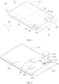
FIG. 1 is a schematic structural diagram of a battery according to an embodiment of this application; -
FIG. 2 is a structural exploded view ofFIG. 1 ; -
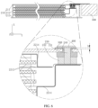
FIG. 3 is a schematic cross-sectional view along line AA inFIG. 1 ; -
FIG. 4 is a schematic diagram of an electrode assembly according to another embodiment of this application; -
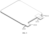
FIG. 5 is a schematic diagram of an electrode assembly being a stacked structure according to an embodiment of this application; -
FIG. 6 is a schematic cross-sectional view along line BB inFIG. 1 ; -
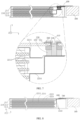
FIG. 7 is a schematic cross-sectional view along line BB inFIG. 1 in another case; -
FIG. 8 is a schematic cross-sectional view along line CC inFIG. 1 ; -
FIG. 9 is a schematic cross-sectional view along line CC inFIG. 1 in another case; and -
FIG. 10 is a structural block diagram of an electronic apparatus according to another embodiment of this application. - Reference numerals in the accompanying drawings are described as follows: 100. battery; 200. cell; 300. circuit board; 400. first conductive member; 500. insulating member; 600. conductive sheet; 700. second conductive member; and 900. electronic apparatus;
- 210. housing; 220. electrode assembly; 230. pole; 240. bonding member; 211. first housing plate; 212. middle frame; and 213. second housing plate;
- 221. first electrode plate; 222. second electrode plate; 223. separator; 231. connecting portion; 232. protruding edge portion; 2211. first current collector; 2212. first protrusion; 2213. first active substance layer; 2214. first insulating medium; 2221. second current collector; 2222. second protrusion; 2223. second active substance; 2224. second insulating medium; 2101. first surface; 2102. second surface; 2103. first avoidance opening; and 410. bulge.
- For ease of understanding of this application, the following describes this application in more detail with reference to the accompanying drawings and specific embodiments. It should be noted that when an element is "fixed to" another element, the element may be directly on the another element, or there may be one or more elements between the elements. When an element is "connected to" another element, the element may be directly connected to the another element, or there may be one or more elements between the elements. In the descriptions of this application, the orientations or positional relationships indicated by the terms "up", "down", "inside", "outside", "perpendicular", "horizontal", and the like are based on the orientations or positional relationships shown in the accompanying drawings. Such terms are intended merely for the ease and brevity of description of this application without indicating or implying that the apparatuses or components mentioned in this application must have specified orientations or must be constructed and operated in the specified orientations, and therefore shall not be construed as any limitations on this application. In addition, the terms "first" and "second" are merely intended for a purpose of description, and shall not be understood as an indication or implication of relative importance.
- Unless otherwise defined, all technical and scientific terms used in this specification shall have the same meanings as those commonly understood by a person skilled in the art to which this application pertains. The terms used in this specification of this application are only used to describe specific embodiments, and are not intended to limit this application. The term "and/or" used in this specification includes any and all combinations of one or more relevant listed items.
- In addition, technical features involved in different embodiments of this application that are described below may be combined as long as they do not conflict with each other.
- As shown in
FIGs. 1 and 2 , abattery 100 provided by an embodiment of this application includes acell 200 and acircuit board 300, where thecircuit board 300 is disposed at thecell 200. - As shown in
FIGs. 2 and3 , thecell 200 includes ahousing 210, anelectrode assembly 220, and apole 230. Theelectrode assembly 220 is accommodated in thehousing 210, thepole 230 is mounted in thehousing 210, and thepole 230 is connected to theelectrode assembly 220, thepole 230 being configured to be connected to thecircuit board 300. - The
housing 210 may be of multiple structures as long as it can accommodate theelectrode assembly 220 and thepole 230. In a case, as shown inFIG. 3 , thehousing 210 includes afirst housing plate 211, amiddle frame 212, and asecond housing plate 213 sequentially connected. Thefirst housing plate 211, themiddle frame 212, and thesecond housing plate 213 jointly enclose an accommodating space, and theelectrode assembly 220 is accommodated in the accommodating space. In another case, thesecond housing plate 213 and themiddle frame 212 form an integral member, which may be prepared through process such as die casting or punching, and thefirst housing plate 211 covers the foregoing integral member to form an accommodating space. - The
electrode assembly 220 includes afirst electrode plate 221, asecond electrode plate 222, and aseparator 223. Theseparator 223 is disposed between thefirst electrode plate 221 and thesecond electrode plate 222, and theseparator 223 is configured to reduce the risk of short circuit between thefirst electrode plate 221 and thesecond electrode plate 222. Thefirst electrode plate 221 and thesecond electrode plate 222 have different polarities. For example, if thefirst electrode plate 221 is a positive electrode plate, thesecond electrode plate 222 is a negative electrode plate; otherwise, if thefirst electrode plate 221 is a negative electrode plate, thesecond electrode plate 222 is a positive electrode plate. - It can be understood that the
electrode assembly 220 may be of a wound structure or a stacked structure, which is specifically determined based on requirements. As shown inFIG. 3 , theelectrode assembly 220 is of a stacked structure. In this case, there are multiplefirst electrode plates 221,separators 223, andsecond electrode plates 222, and the multiplefirst electrode plates 221,separators 223, andsecond electrode plates 222 are stacked. Theseparator 223 is disposed between thefirst electrode plate 221 and thesecond electrode plate 222 adjacent to each other, multiplefirst electrode plates 221 having the same polarity are interconnected, and multiplesecond electrode plates 222 are interconnected. In addition, as shown inFIG. 4 , theelectrode assembly 220 is of a wound structure. In this case, thefirst electrode plate 221, theseparator 223, and thesecond electrode plate 222 are stacked and wound. It should be understood that when theelectrode assembly 220 is of a stacked structure, the thickness direction of theelectrode assembly 220 and the thickness direction of thecell 200 may be the same or different. In this embodiment, theelectrode assembly 220 is of a stacked structure, and the thickness direction of theelectrode assembly 220 and the thickness direction of thecell 200 are the same, the thickness direction of thecell 200 being the thickness direction of thebattery 100. The thickness direction of thecell 200 is defined as a first direction X, and in the first direction X, thecell 200 has a size of t satisfying 1.5 mm≤t≤3 mm. - Referring to
FIGs. 5 and6 , thefirst electrode plate 221 includes a firstcurrent collector 2211 and afirst protrusion 2212 protruding from an edge of the firstcurrent collector 2211, where the surface of the firstcurrent collector 2211 is coated with a firstactive substance layer 2213.First protrusions 2212 of multiplefirst electrode plates 221 are interconnected. Similarly, referring toFIGs. 7 and 8 , thesecond electrode plate 222 includes a secondcurrent collector 2221 and asecond protrusion 2222 protruding from an edge of the secondcurrent collector 2221, where the surface of the secondcurrent collector 2221 is coated with a secondactive substance layer 2223.Second protrusions 2222 of multiplesecond electrode plates 222 are interconnected. In this embodiment, multiplefirst protrusions 2212 and multiplesecond protrusions 2222 are all located on the same side, so as to reduce the overall size of theelectrode assembly 220 and increase the energy density of thecell 200. - A direction of the
first protrusion 2212 protruding from the firstcurrent collector 2211 is defined as a second direction Y, the first direction X being perpendicular to the second direction Y, and a direction perpendicular to the first direction X and the second direction Y is a third direction Z. - It should be understood that in the first direction X, the surface on the outermost side of the
first protrusion 2212 is provided with a first insulatingmedium 2214. The firstinsulating medium 2214 is configured to insulate thefirst protrusion 2212 from thehousing 210, and the first insulatingmedium 2214 can further reduce the risk of thehousing 210 being pierced by burrs on the surface of thefirst protrusion 2212, improving the safety performance of thecell 200. Similarly, in the first direction X, the surface on the outermost side of thesecond protrusion 2222 is provided with a secondinsulating medium 2224. The secondinsulating medium 2224 is configured to reduce the risk of thehousing 210 being pierced by burrs on the surface of thesecond protrusion 2222, improving the safety performance of thecell 200. In this embodiment, the first insulatingmedium 2214 and the second insulating medium 2224 are both insulating adhesive paper. Certainly, the first insulatingmedium 2214 and the second insulating medium 2224 may alternatively be made of other materials, and are not limited to the insulating adhesive paper mentioned in this embodiment. - The quantity of the
poles 230 may be set based on requirements, and one or more poles may be provided. In this embodiment, onepole 230 is provided, and thepole 230 may be connected to thefirst electrode plate 221 or thesecond electrode plate 222. In this case, thepole 230 is used as one of the electrodes of thecell 200. For ease of description, the solution of this application is described using an example in which thepole 230 is connected to thefirst electrode plate 221. Thesecond electrode plate 222 is connected to thehousing 210, and thus thehousing 210 is used as another electrode of thecell 200. - In some embodiments, referring to
FIGs. 2 and6 , thehousing 210 includes afirst surface 2101 and asecond surface 2102 adjacent to thefirst surface 2101. Thehousing 210 is provided with afirst avoidance opening 2103 running through thefirst surface 2101 along the first direction X, and thepole 230 is disposed at thefirst avoidance opening 2103. - The
cell 200 further includes abonding member 240, where thebonding member 240 is disposed between thehousing 210 and thepole 230, and thebonding member 240 is configured to fixedly bond thepole 230 in thehousing 210. In this embodiment, thepole 230 includes a connectingportion 231 and a protrudingedge portion 232 protruding from the connectingportion 231. The connectingportion 231 is disposed at thefirst avoidance opening 2103, thebonding member 240 is disposed at one end of the protrudingedge portion 232 facing thefirst avoidance opening 2103, and thebonding member 240 bonds the protrudingedge portion 232 to an inner surface of thehousing 210, helping to quickly mount thepole 230 on thehousing 210. In this way, thepole 230 may be at least partially disposed in thehousing 210, and thepole 230 may be connected to the outside via thefirst avoidance opening 2103. This helps to reduce the impact of thepole 230 on the thickness of thecell 200 and manufacture thethinner cell 200, thus increasing the energy density of thebattery 100. It should be understood that the size of the outer periphery of the protrudingedge portion 232 needs to be greater than the size of thefirst avoidance opening 2103, reducing the possibility that the protrudingedge portion 232 freely drops out of thehousing 210. - The
bonding member 240 is a connecting member made of an adhesive insulating material, to reduce the risk of short circuit between thepole 230 and thehousing 210 due to contact. In this embodiment, thebonding member 240 is made of a PP material with maleic anhydride functional groups. Certainly, thebonding member 240 may alternatively be another connecting member such as a double-sided tape. - Further, as shown in
FIG. 6 , a gap is present between the protrudingedge portion 232 and a wall surface of thefirst avoidance opening 2103, and thebonding member 240 fills the gap to seal thefirst avoidance opening 2103. In other words, the connectingportion 231 is located in thefirst avoidance opening 2103, and thebonding member 240 is disposed between thepole 230 and thefirst avoidance opening 2103, which can reduce the risk of short circuit between the connectingportion 231 and thehousing 210, thus improving the safety performance of thecell 200. - In some embodiments, the
circuit board 300 is disposed on thesecond surface 2102 of thehousing 210, and thebattery 100 further includes a firstconductive member 400. One end of the firstconductive member 400 is connected to thepole 230, and another end of the firstconductive member 400 is connected to thecircuit board 300. In this way, thecircuit board 300 and thepole 230 are respectively located on two surfaces of thehousing 210. Without constraint from the size of thepole 230, thecell 200 may be designed thinner, helping to increase the energy density of thecell 200, thus widening the application range of thebattery 100. - In some embodiments, the
battery 100 further includes an insulatingmember 500. The insulatingmember 500 is disposed between thefirst surface 2101 and the firstconductive member 400, and the insulatingmember 500 is configured to reduce the risk of short circuit between the firstconductive member 400 and thefirst surface 2101 of thehousing 210. In this embodiment, thehousing 210 is made of conductive metal. It should be understood that in the first direction X, the insulatingmember 500 is hollowed out above thefirst avoidance opening 2103, to allow the insulatingmember 500 to impede less the connection between the firstconductive member 400 and thepole 230. - It should be understood that when the
pole 230 has different heights, the insulatingmember 500 may be mounted in different manners. In a case, as shown inFIG. 6 , when viewed from the third direction Z, one end of thepole 230 protrudes from thefirst surface 2101. In addition, the insulatingmember 500 fits around thepole 230. In this case, thepole 230 protrudes from thefirst surface 2101 by a height of h satisfying h≤0.3 mm. In another case, as shown inFIG. 7 , thepole 230 is located in thefirst avoidance opening 2103, that is, thepole 230 does not protrude from thefirst surface 2101. In this case, the firstconductive member 400 is provided with abulge 410, and thebulge 410 extends into thefirst avoidance opening 2103 to be connected to thepole 230. In this case, the insulatingmember 500 fits around thebulge 410. - In the foregoing two cases, when viewed from the second direction Y, in the third direction Z, the size of the insulating
member 500 is larger than the size of the firstconductive member 400, helping to reduce the risk of short circuit between the firstconductive member 400 and thehousing 210, thus improving the safety performance of thebattery 100. - In some embodiments, referring to
FIGs. 1 and8 , thebattery 100 includes aconductive sheet 600 and a secondconductive member 700. Theconductive sheet 600 is mounted on thefirst surface 2101, one end of the secondconductive member 700 is connected to theconductive sheet 600, and another end of the secondconductive member 700 is connected to thecircuit board 300. Thesecond protrusion 2222 of thesecond electrode plate 222 is conductively connected to thehousing 210. In this embodiment, thehousing 210 is made of conductive metal, and thehousing 210 is directly used as another electrode of thecell 200, so as to electrically connect thehousing 210 to thecircuit board 300 under the action of theconductive sheet 600 and the secondconductive member 700. - In some other embodiments, the
housing 210 is made of an insulating material, for example, plastic. In addition, thehousing 210 is provided with a second avoidance opening (not shown in the figure) running through thefirst surface 2101. As shown inFIG. 9 , anotherpole 230 and anotherbonding member 240 are mounted at the second avoidance opening, and the anotherbonding member 240 bonds the anotherpole 230 to the second avoidance opening. Asecond protrusion 2222 of thesecond electrode plate 222 is connected to the anotherpole 230, one end of the secondconductive member 700 is connected to the anotherpole 230, and another end of the secondconductive member 700 is connected to thecircuit board 300. In this embodiment, theconductive sheet 600 may be omitted. In this way, the another electrode of thecell 200 is also connected to thecircuit board 300. - The
battery 100 provided by some embodiments of this application includes acell 200. Thecell 200 includes ahousing 210, anelectrode assembly 220, apole 230, and abonding member 240, theelectrode assembly 220 being accommodated in thehousing 210. Thehousing 210 includes afirst surface 2101 in a thickness direction of thebattery 100, and thehousing 210 is provided with afirst avoidance opening 2103 running through thefirst surface 2101 along the first direction X. Thepole 230 is disposed at thefirst avoidance opening 2103, thebonding member 240 is disposed between thepole 230 and thehousing 210, and thebonding member 240 is configured to bond thepole 230 to thehousing 210. In this way, thepole 230 may be at least partially disposed in thehousing 210, and thepole 230 may be connected to the outside via thefirst avoidance opening 2103. This helps to reduce the impact of the size of thepole 230 on the thickness of thecell 200 and manufacture thethinner cell 200, thus increasing the energy density of thebattery 100. - As shown in
FIG. 10 , an electronic apparatus 900 provided in another embodiment of this application includes thebattery 100 of the foregoing embodiments. The electronic apparatus 900 in this application is not particularly limited, and the electronic apparatus may be any known electronic apparatus in the prior art. For example, the electronic apparatus 900 includes but is not limited to a notebook computer, a pen-input computer, a mobile computer, an electronic book player, a portable telephone, a portable fax machine, a portable copier, a portable printer, a stereo headset, a video recorder, a liquid crystal television, a portable cleaner, a portable CD player, a mini-disc, a transceiver, an electronic notepad, a calculator, a memory card, a portable recorder, a radio, a standby power source, a motor, an automobile, a motorcycle, a power-assisted bicycle, a bicycle, a lighting appliance, a toy, a game console, a clock, an electric tool, a flash lamp, a camera, a large household battery, or a lithium-ion capacitor. - The above description is only some embodiments of this application and does not limit the scope of this application. Any equivalent structures or equivalent process transformations made based on the description and drawings of this application, or their direct or indirect application in other related technical fields, are all included within the protection scope of this application.
Claims (12)
- A battery, comprising a cell, wherein the cell comprises a housing and an electrode assembly accommodated in the housing, whereinthe housing comprises a first surface in a thickness direction of the battery, and the housing is provided with a first avoidance opening running through the first surface along the thickness direction of the battery; andthe cell further comprises a bonding member and a pole, wherein the pole is provided at the first avoidance opening, the pole is connected to the electrode assembly, and the bonding member is disposed between the housing and the pole.
- The battery according to claim 1, wherein the battery further comprises a circuit board and a first conductive member, the housing comprises a second surface adjacent to the first surface, the circuit board is disposed on the second surface, one end of the first conductive member is connected to the pole, and another end of the first conductive member is connected to the circuit board.
- The battery according to claim 2, wherein the pole comprises a connecting portion and a protruding edge portion protruding from the connecting portion, wherein the connecting portion is disposed at the first avoidance opening, the bonding member is disposed at one end of the protruding edge portion facing the first avoidance opening, and the bonding member bonds the protruding edge portion to an inner surface of the housing.
- The battery according to claim 3, wherein a gap is present between the connecting portion and a wall surface of the first avoidance opening, and the bonding member fills the gap, to seal the first avoidance opening.
- The battery according to claim 2, wherein the thickness direction of the cell is a first direction, a direction perpendicular to the second surface is a second direction, a direction perpendicular to the first direction and the second direction is a third direction, and when viewed from the third direction, one end of the pole protrudes from the first surface, and
the battery further comprises an insulating member, wherein the insulating member fits around the pole, the insulating member is disposed between the first surface and the first conductive member, and the insulating member is configured to insulate the housing from the first conductive member. - The battery according to claim 2, wherein the first conductive member is provided with a bulge, the bulge extending into the first avoidance opening to be connected to the pole, and
the battery further comprises an insulating member, wherein the insulating member fits around the bulge, the insulating member is disposed between the first surface and the first conductive member, and the insulating member is configured to insulate the housing from the first conductive member. - The battery according to claim 1, wherein the electrode assembly comprises a first electrode plate, wherein the first electrode plate comprises a first current collector and a first protrusion protruding from an edge of the first current collector, and the first protrusion is connected to the pole.
- The battery according to claim 2, wherein the electrode assembly further comprises a second electrode plate, wherein the second electrode plate comprises a second current collector and a second protrusion protruding from an edge of the second current collector, and
the battery further comprises a conductive sheet and a second conductive member, wherein the conductive sheet is connected to the housing, the second protrusion is conductively connected to the housing, one end of the second conductive member is connected to the conductive sheet, and another end of the second conductive member is connected to the circuit board. - The battery according to claim 1, wherein the electrode assembly comprises multiple first electrode plates, multiple separators, and multiple second electrode plates, wherein the multiple first electrode plates, the multiple separators, and the multiple second electrode plates are stacked along a first direction, and the separator is disposed between the first electrode plate and the second electrode plate adjacent to each other, the first direction being the thickness direction of the cell.
- The battery according to any one of claims 1 to 9, wherein the housing comprises a first housing plate, a middle frame, and a second housing plate, wherein the first housing plate and the second housing plate are both connected to the middle frame, so as to form an accommodating cavity accommodating the electrode assembly.
- The battery according to claim 1, wherein the thickness direction of the cell is a first direction, and in the first direction, the cell has a size of t satisfying 1.5 mm≤t≤3 mm.
- An electronic apparatus, comprising the battery according to any one of claims 1 to 11.
Applications Claiming Priority (2)
| Application Number | Priority Date | Filing Date | Title |
|---|---|---|---|
| CN202211406648.XA CN115588769B (en) | 2022-11-10 | 2022-11-10 | A kind of battery and electronic device |
| PCT/CN2023/124023 WO2024099021A1 (en) | 2022-11-10 | 2023-10-11 | Battery and electronic apparatus |
Publications (2)
| Publication Number | Publication Date |
|---|---|
| EP4583215A1 true EP4583215A1 (en) | 2025-07-09 |
| EP4583215A4 EP4583215A4 (en) | 2026-04-22 |
Family
ID=84782142
Family Applications (1)
| Application Number | Title | Priority Date | Filing Date |
|---|---|---|---|
| EP23887713.8A Pending EP4583215A4 (en) | 2022-11-10 | 2023-10-11 | BATTERY AND ELECTRONIC DEVICE |
Country Status (4)
| Country | Link |
|---|---|
| US (1) | US20250266488A1 (en) |
| EP (1) | EP4583215A4 (en) |
| CN (1) | CN115588769B (en) |
| WO (1) | WO2024099021A1 (en) |
Families Citing this family (2)
| Publication number | Priority date | Publication date | Assignee | Title |
|---|---|---|---|---|
| CN115588769B (en) * | 2022-11-10 | 2023-03-14 | 宁德新能源科技有限公司 | A kind of battery and electronic device |
| CN115966820B (en) * | 2023-03-16 | 2023-07-18 | 宁德新能源科技有限公司 | Batteries and electrical equipment |
Family Cites Families (12)
| Publication number | Priority date | Publication date | Assignee | Title |
|---|---|---|---|---|
| KR100358805B1 (en) * | 2000-03-07 | 2002-10-25 | 삼성에스디아이 주식회사 | Negative active material for lithium secondary battery and method of preparing same |
| US8778530B2 (en) * | 2010-09-10 | 2014-07-15 | Samsung Sdi Co., Ltd. | Battery and battery pack using the same |
| CN206322803U (en) * | 2016-12-28 | 2017-07-11 | 东莞鑫电能源有限公司 | A lithium-ion battery with a high active material ratio |
| CN111370605A (en) * | 2018-12-25 | 2020-07-03 | 林州朗坤科技有限公司 | A kind of electrochemical device and preparation method thereof |
| CN211605201U (en) * | 2020-03-31 | 2020-09-29 | 宁德新能源科技有限公司 | Battery and powered device having the same |
| CN115885414B (en) * | 2020-07-02 | 2025-10-24 | 宁德新能源科技有限公司 | Batteries and electronic devices |
| CN212434755U (en) * | 2020-08-18 | 2021-01-29 | 嘉兴模度新能源有限公司 | Self-locking battery module |
| CN214411401U (en) * | 2021-03-15 | 2021-10-15 | 东莞新能德科技有限公司 | Steel shell battery and electronic device |
| CN114223077A (en) * | 2021-03-31 | 2022-03-22 | 宁德新能源科技有限公司 | Battery and electric equipment |
| CN114039172B (en) * | 2021-11-12 | 2025-08-08 | 欣旺达动力科技股份有限公司 | Single cells and battery packs |
| CN114583415B (en) * | 2022-04-15 | 2022-08-09 | 宁德新能源科技有限公司 | Battery and electronic device |
| CN115588769B (en) * | 2022-11-10 | 2023-03-14 | 宁德新能源科技有限公司 | A kind of battery and electronic device |
-
2022
- 2022-11-10 CN CN202211406648.XA patent/CN115588769B/en active Active
-
2023
- 2023-10-11 WO PCT/CN2023/124023 patent/WO2024099021A1/en not_active Ceased
- 2023-10-11 EP EP23887713.8A patent/EP4583215A4/en active Pending
-
2025
- 2025-05-09 US US19/203,497 patent/US20250266488A1/en active Pending
Also Published As
| Publication number | Publication date |
|---|---|
| CN115588769B (en) | 2023-03-14 |
| WO2024099021A1 (en) | 2024-05-16 |
| EP4583215A4 (en) | 2026-04-22 |
| US20250266488A1 (en) | 2025-08-21 |
| CN115588769A (en) | 2023-01-10 |
Similar Documents
| Publication | Publication Date | Title |
|---|---|---|
| EP4207477A1 (en) | Electrochemical device and electronic device | |
| US20250266488A1 (en) | Battery and electronic apparatus | |
| EP4109617A2 (en) | Electrochemical apparatus and electronic apparatus | |
| JP4628682B2 (en) | Battery unit and lithium secondary battery using the same | |
| CN104377339B (en) | Rechargeable battery | |
| US10553905B2 (en) | Battery cell of novel structure with improved safety | |
| CN102856523A (en) | Rechargeable battery | |
| WO2024104222A1 (en) | Battery and electrical device | |
| US20230261335A1 (en) | Battery and electronic device having same | |
| US20250046966A1 (en) | Battery and electronic device | |
| CN115332696A (en) | Battery and electric equipment | |
| CN214378578U (en) | Battery pack and electronic device | |
| WO2024140498A1 (en) | Electrochemical apparatus and electrical device | |
| CN116581396A (en) | Batteries and electrical equipment | |
| EP4583274A1 (en) | Battery module, battery pack, and electric apparatus | |
| EP4095990A1 (en) | Battery cell, battery pack, and electronic device | |
| WO2024221820A1 (en) | Negative electrode sheet, secondary battery, battery module, battery pack, and electric apparatus | |
| KR20150006649A (en) | Battery Pack | |
| CN223436664U (en) | Single cells and battery packs | |
| CN219286613U (en) | Electrochemical device and electronic device | |
| CN218769976U (en) | Battery and electronic equipment | |
| EP4503313A1 (en) | Battery module | |
| EP4651252A1 (en) | Battery cell and electrical device | |
| US20260045515A1 (en) | Carbon fiber electrode sheet, lithium metal battery, battery module, battery pack, and electric device | |
| WO2026007458A1 (en) | Battery cell, battery, electric device, and energy storage device |
Legal Events
| Date | Code | Title | Description |
|---|---|---|---|
| STAA | Information on the status of an ep patent application or granted ep patent |
Free format text: STATUS: THE INTERNATIONAL PUBLICATION HAS BEEN MADE |
|
| PUAI | Public reference made under article 153(3) epc to a published international application that has entered the european phase |
Free format text: ORIGINAL CODE: 0009012 |
|
| STAA | Information on the status of an ep patent application or granted ep patent |
Free format text: STATUS: REQUEST FOR EXAMINATION WAS MADE |
|
| 17P | Request for examination filed |
Effective date: 20250331 |
|
| AK | Designated contracting states |
Kind code of ref document: A1 Designated state(s): AL AT BE BG CH CY CZ DE DK EE ES FI FR GB GR HR HU IE IS IT LI LT LU LV MC ME MK MT NL NO PL PT RO RS SE SI SK SM TR |
|
| DAV | Request for validation of the european patent (deleted) | ||
| DAX | Request for extension of the european patent (deleted) | ||
| A4 | Supplementary search report drawn up and despatched |
Effective date: 20260324 |
|
| RIC1 | Information provided on ipc code assigned before grant |
Ipc: H01M 10/04 20060101AFI20260318BHEP Ipc: H01M 50/553 20210101ALI20260318BHEP Ipc: H01M 50/176 20210101ALI20260318BHEP Ipc: H01M 50/186 20210101ALI20260318BHEP Ipc: H01M 50/54 20210101ALI20260318BHEP Ipc: H01M 50/557 20210101ALI20260318BHEP Ipc: H01M 50/103 20210101ALI20260318BHEP |