EP4207477A1 - Electrochemical device and electronic device - Google Patents
Electrochemical device and electronic device Download PDFInfo
- Publication number
- EP4207477A1 EP4207477A1 EP22827421.3A EP22827421A EP4207477A1 EP 4207477 A1 EP4207477 A1 EP 4207477A1 EP 22827421 A EP22827421 A EP 22827421A EP 4207477 A1 EP4207477 A1 EP 4207477A1
- Authority
- EP
- European Patent Office
- Prior art keywords
- tabs
- electrode plate
- electrode assembly
- sub
- connecting portion
- Prior art date
- Legal status (The legal status is an assumption and is not a legal conclusion. Google has not performed a legal analysis and makes no representation as to the accuracy of the status listed.)
- Pending
Links
- 238000004804 winding Methods 0.000 claims abstract description 7
- 238000003466 welding Methods 0.000 claims description 28
- 238000005452 bending Methods 0.000 claims description 20
- 239000011149 active material Substances 0.000 claims description 7
- 239000010410 layer Substances 0.000 description 58
- 238000004519 manufacturing process Methods 0.000 description 7
- 239000003792 electrolyte Substances 0.000 description 5
- HBBGRARXTFLTSG-UHFFFAOYSA-N Lithium ion Chemical compound [Li+] HBBGRARXTFLTSG-UHFFFAOYSA-N 0.000 description 4
- 229910001416 lithium ion Inorganic materials 0.000 description 4
- 238000007789 sealing Methods 0.000 description 4
- 239000003990 capacitor Substances 0.000 description 3
- 239000011888 foil Substances 0.000 description 3
- 229910052744 lithium Inorganic materials 0.000 description 3
- WHXSMMKQMYFTQS-UHFFFAOYSA-N Lithium Chemical group [Li] WHXSMMKQMYFTQS-UHFFFAOYSA-N 0.000 description 2
- PXHVJJICTQNCMI-UHFFFAOYSA-N Nickel Chemical compound [Ni] PXHVJJICTQNCMI-UHFFFAOYSA-N 0.000 description 2
- 229910052751 metal Inorganic materials 0.000 description 2
- 239000002184 metal Substances 0.000 description 2
- 229920000642 polymer Polymers 0.000 description 2
- RYGMFSIKBFXOCR-UHFFFAOYSA-N Copper Chemical compound [Cu] RYGMFSIKBFXOCR-UHFFFAOYSA-N 0.000 description 1
- 239000012790 adhesive layer Substances 0.000 description 1
- 229910052782 aluminium Inorganic materials 0.000 description 1
- XAGFODPZIPBFFR-UHFFFAOYSA-N aluminium Chemical compound [Al] XAGFODPZIPBFFR-UHFFFAOYSA-N 0.000 description 1
- 239000011889 copper foil Substances 0.000 description 1
- 238000005520 cutting process Methods 0.000 description 1
- 230000007812 deficiency Effects 0.000 description 1
- 230000000593 degrading effect Effects 0.000 description 1
- 238000003487 electrochemical reaction Methods 0.000 description 1
- 238000004146 energy storage Methods 0.000 description 1
- 238000005516 engineering process Methods 0.000 description 1
- 239000000446 fuel Substances 0.000 description 1
- 238000003780 insertion Methods 0.000 description 1
- 230000037431 insertion Effects 0.000 description 1
- 239000004973 liquid crystal related substance Substances 0.000 description 1
- 238000012986 modification Methods 0.000 description 1
- 230000004048 modification Effects 0.000 description 1
- 238000004806 packaging method and process Methods 0.000 description 1
- 238000012856 packing Methods 0.000 description 1
- 239000002985 plastic film Substances 0.000 description 1
- 229920006255 plastic film Polymers 0.000 description 1
- 239000000779 smoke Substances 0.000 description 1
Images


Classifications
-
- H—ELECTRICITY
- H01—ELECTRIC ELEMENTS
- H01M—PROCESSES OR MEANS, e.g. BATTERIES, FOR THE DIRECT CONVERSION OF CHEMICAL ENERGY INTO ELECTRICAL ENERGY
- H01M50/00—Constructional details or processes of manufacture of the non-active parts of electrochemical cells other than fuel cells, e.g. hybrid cells
- H01M50/50—Current conducting connections for cells or batteries
- H01M50/528—Fixed electrical connections, i.e. not intended for disconnection
-
- H—ELECTRICITY
- H01—ELECTRIC ELEMENTS
- H01M—PROCESSES OR MEANS, e.g. BATTERIES, FOR THE DIRECT CONVERSION OF CHEMICAL ENERGY INTO ELECTRICAL ENERGY
- H01M10/00—Secondary cells; Manufacture thereof
- H01M10/04—Construction or manufacture in general
-
- H—ELECTRICITY
- H01—ELECTRIC ELEMENTS
- H01M—PROCESSES OR MEANS, e.g. BATTERIES, FOR THE DIRECT CONVERSION OF CHEMICAL ENERGY INTO ELECTRICAL ENERGY
- H01M10/00—Secondary cells; Manufacture thereof
- H01M10/04—Construction or manufacture in general
- H01M10/0431—Cells with wound or folded electrodes
-
- H—ELECTRICITY
- H01—ELECTRIC ELEMENTS
- H01M—PROCESSES OR MEANS, e.g. BATTERIES, FOR THE DIRECT CONVERSION OF CHEMICAL ENERGY INTO ELECTRICAL ENERGY
- H01M10/00—Secondary cells; Manufacture thereof
- H01M10/05—Accumulators with non-aqueous electrolyte
- H01M10/052—Li-accumulators
- H01M10/0525—Rocking-chair batteries, i.e. batteries with lithium insertion or intercalation in both electrodes; Lithium-ion batteries
-
- H—ELECTRICITY
- H01—ELECTRIC ELEMENTS
- H01M—PROCESSES OR MEANS, e.g. BATTERIES, FOR THE DIRECT CONVERSION OF CHEMICAL ENERGY INTO ELECTRICAL ENERGY
- H01M10/00—Secondary cells; Manufacture thereof
- H01M10/05—Accumulators with non-aqueous electrolyte
- H01M10/058—Construction or manufacture
- H01M10/0587—Construction or manufacture of accumulators having only wound construction elements, i.e. wound positive electrodes, wound negative electrodes and wound separators
-
- H—ELECTRICITY
- H01—ELECTRIC ELEMENTS
- H01M—PROCESSES OR MEANS, e.g. BATTERIES, FOR THE DIRECT CONVERSION OF CHEMICAL ENERGY INTO ELECTRICAL ENERGY
- H01M50/00—Constructional details or processes of manufacture of the non-active parts of electrochemical cells other than fuel cells, e.g. hybrid cells
- H01M50/10—Primary casings; Jackets or wrappings
- H01M50/102—Primary casings; Jackets or wrappings characterised by their shape or physical structure
- H01M50/103—Primary casings; Jackets or wrappings characterised by their shape or physical structure prismatic or rectangular
-
- H—ELECTRICITY
- H01—ELECTRIC ELEMENTS
- H01M—PROCESSES OR MEANS, e.g. BATTERIES, FOR THE DIRECT CONVERSION OF CHEMICAL ENERGY INTO ELECTRICAL ENERGY
- H01M50/00—Constructional details or processes of manufacture of the non-active parts of electrochemical cells other than fuel cells, e.g. hybrid cells
- H01M50/10—Primary casings; Jackets or wrappings
- H01M50/102—Primary casings; Jackets or wrappings characterised by their shape or physical structure
- H01M50/105—Pouches or flexible bags
-
- H—ELECTRICITY
- H01—ELECTRIC ELEMENTS
- H01M—PROCESSES OR MEANS, e.g. BATTERIES, FOR THE DIRECT CONVERSION OF CHEMICAL ENERGY INTO ELECTRICAL ENERGY
- H01M50/00—Constructional details or processes of manufacture of the non-active parts of electrochemical cells other than fuel cells, e.g. hybrid cells
- H01M50/10—Primary casings; Jackets or wrappings
- H01M50/116—Primary casings; Jackets or wrappings characterised by the material
- H01M50/117—Inorganic material
- H01M50/119—Metals
-
- H—ELECTRICITY
- H01—ELECTRIC ELEMENTS
- H01M—PROCESSES OR MEANS, e.g. BATTERIES, FOR THE DIRECT CONVERSION OF CHEMICAL ENERGY INTO ELECTRICAL ENERGY
- H01M50/00—Constructional details or processes of manufacture of the non-active parts of electrochemical cells other than fuel cells, e.g. hybrid cells
- H01M50/10—Primary casings; Jackets or wrappings
- H01M50/172—Arrangements of electric connectors penetrating the casing
- H01M50/174—Arrangements of electric connectors penetrating the casing adapted for the shape of the cells
- H01M50/178—Arrangements of electric connectors penetrating the casing adapted for the shape of the cells for pouch or flexible bag cells
-
- H—ELECTRICITY
- H01—ELECTRIC ELEMENTS
- H01M—PROCESSES OR MEANS, e.g. BATTERIES, FOR THE DIRECT CONVERSION OF CHEMICAL ENERGY INTO ELECTRICAL ENERGY
- H01M50/00—Constructional details or processes of manufacture of the non-active parts of electrochemical cells other than fuel cells, e.g. hybrid cells
- H01M50/50—Current conducting connections for cells or batteries
- H01M50/531—Electrode connections inside a battery casing
- H01M50/533—Electrode connections inside a battery casing characterised by the shape of the leads or tabs
-
- H—ELECTRICITY
- H01—ELECTRIC ELEMENTS
- H01M—PROCESSES OR MEANS, e.g. BATTERIES, FOR THE DIRECT CONVERSION OF CHEMICAL ENERGY INTO ELECTRICAL ENERGY
- H01M50/00—Constructional details or processes of manufacture of the non-active parts of electrochemical cells other than fuel cells, e.g. hybrid cells
- H01M50/50—Current conducting connections for cells or batteries
- H01M50/531—Electrode connections inside a battery casing
- H01M50/534—Electrode connections inside a battery casing characterised by the material of the leads or tabs
-
- H—ELECTRICITY
- H01—ELECTRIC ELEMENTS
- H01M—PROCESSES OR MEANS, e.g. BATTERIES, FOR THE DIRECT CONVERSION OF CHEMICAL ENERGY INTO ELECTRICAL ENERGY
- H01M50/00—Constructional details or processes of manufacture of the non-active parts of electrochemical cells other than fuel cells, e.g. hybrid cells
- H01M50/50—Current conducting connections for cells or batteries
- H01M50/531—Electrode connections inside a battery casing
- H01M50/536—Electrode connections inside a battery casing characterised by the method of fixing the leads to the electrodes, e.g. by welding
-
- H—ELECTRICITY
- H01—ELECTRIC ELEMENTS
- H01M—PROCESSES OR MEANS, e.g. BATTERIES, FOR THE DIRECT CONVERSION OF CHEMICAL ENERGY INTO ELECTRICAL ENERGY
- H01M50/00—Constructional details or processes of manufacture of the non-active parts of electrochemical cells other than fuel cells, e.g. hybrid cells
- H01M50/50—Current conducting connections for cells or batteries
- H01M50/531—Electrode connections inside a battery casing
- H01M50/538—Connection of several leads or tabs of wound or folded electrode stacks
-
- H—ELECTRICITY
- H01—ELECTRIC ELEMENTS
- H01M—PROCESSES OR MEANS, e.g. BATTERIES, FOR THE DIRECT CONVERSION OF CHEMICAL ENERGY INTO ELECTRICAL ENERGY
- H01M50/00—Constructional details or processes of manufacture of the non-active parts of electrochemical cells other than fuel cells, e.g. hybrid cells
- H01M50/50—Current conducting connections for cells or batteries
- H01M50/543—Terminals
- H01M50/547—Terminals characterised by the disposition of the terminals on the cells
- H01M50/55—Terminals characterised by the disposition of the terminals on the cells on the same side of the cell
-
- H—ELECTRICITY
- H01—ELECTRIC ELEMENTS
- H01M—PROCESSES OR MEANS, e.g. BATTERIES, FOR THE DIRECT CONVERSION OF CHEMICAL ENERGY INTO ELECTRICAL ENERGY
- H01M50/00—Constructional details or processes of manufacture of the non-active parts of electrochemical cells other than fuel cells, e.g. hybrid cells
- H01M50/50—Current conducting connections for cells or batteries
- H01M50/543—Terminals
- H01M50/552—Terminals characterised by their shape
- H01M50/553—Terminals adapted for prismatic, pouch or rectangular cells
- H01M50/557—Plate-shaped terminals
-
- H—ELECTRICITY
- H01—ELECTRIC ELEMENTS
- H01M—PROCESSES OR MEANS, e.g. BATTERIES, FOR THE DIRECT CONVERSION OF CHEMICAL ENERGY INTO ELECTRICAL ENERGY
- H01M50/00—Constructional details or processes of manufacture of the non-active parts of electrochemical cells other than fuel cells, e.g. hybrid cells
- H01M50/50—Current conducting connections for cells or batteries
- H01M50/543—Terminals
- H01M50/564—Terminals characterised by their manufacturing process
- H01M50/566—Terminals characterised by their manufacturing process by welding, soldering or brazing
-
- H—ELECTRICITY
- H01—ELECTRIC ELEMENTS
- H01M—PROCESSES OR MEANS, e.g. BATTERIES, FOR THE DIRECT CONVERSION OF CHEMICAL ENERGY INTO ELECTRICAL ENERGY
- H01M50/00—Constructional details or processes of manufacture of the non-active parts of electrochemical cells other than fuel cells, e.g. hybrid cells
- H01M50/50—Current conducting connections for cells or batteries
- H01M50/572—Means for preventing undesired use or discharge
- H01M50/584—Means for preventing undesired use or discharge for preventing incorrect connections inside or outside the batteries
- H01M50/59—Means for preventing undesired use or discharge for preventing incorrect connections inside or outside the batteries characterised by the protection means
- H01M50/593—Spacers; Insulating plates
-
- Y—GENERAL TAGGING OF NEW TECHNOLOGICAL DEVELOPMENTS; GENERAL TAGGING OF CROSS-SECTIONAL TECHNOLOGIES SPANNING OVER SEVERAL SECTIONS OF THE IPC; TECHNICAL SUBJECTS COVERED BY FORMER USPC CROSS-REFERENCE ART COLLECTIONS [XRACs] AND DIGESTS
- Y02—TECHNOLOGIES OR APPLICATIONS FOR MITIGATION OR ADAPTATION AGAINST CLIMATE CHANGE
- Y02E—REDUCTION OF GREENHOUSE GAS [GHG] EMISSIONS, RELATED TO ENERGY GENERATION, TRANSMISSION OR DISTRIBUTION
- Y02E60/00—Enabling technologies; Technologies with a potential or indirect contribution to GHG emissions mitigation
- Y02E60/10—Energy storage using batteries
-
- Y—GENERAL TAGGING OF NEW TECHNOLOGICAL DEVELOPMENTS; GENERAL TAGGING OF CROSS-SECTIONAL TECHNOLOGIES SPANNING OVER SEVERAL SECTIONS OF THE IPC; TECHNICAL SUBJECTS COVERED BY FORMER USPC CROSS-REFERENCE ART COLLECTIONS [XRACs] AND DIGESTS
- Y02—TECHNOLOGIES OR APPLICATIONS FOR MITIGATION OR ADAPTATION AGAINST CLIMATE CHANGE
- Y02P—CLIMATE CHANGE MITIGATION TECHNOLOGIES IN THE PRODUCTION OR PROCESSING OF GOODS
- Y02P70/00—Climate change mitigation technologies in the production process for final industrial or consumer products
- Y02P70/50—Manufacturing or production processes characterised by the final manufactured product
Definitions
- This application relates to the field of energy storage technologies, and in particular, to an electrochemical apparatus and an electronic apparatus including such electrochemical apparatus.
- This application provides an electrochemical apparatus, including a housing, an electrode assembly disposed inside the housing, a first tab group, and an adapting piece electrically connected to the first tab group and extending out of the housing.
- the electrode assembly is configured to be a winding structure and includes a first electrode plate.
- the first tab group includes M first tabs, and the first tabs are connected to the electrode plate.
- a thickness direction of the electrode assembly is defined as a first direction. In the first direction, the electrode assembly includes N layers of the first electrode plate, N being greater than M.
- the M first tabs are each connected to the first electrode plate.
- a plane passing through a winding center axis of the electrode assembly and perpendicular to the first direction is defined as a winding center plane.
- the M first tabs are disposed on two sides of the winding center plane.
- the first tab group includes a first connecting portion connected to the first adapting piece and a second connecting portion connected to the first electrode plate, where the M first tabs are stacked to form the first connecting portion. Part of the first tabs at the second connecting portion are connected to a side of the first connecting portion facing the electrode assembly.
- the number M of first tabs is set to be smaller than the layer number N of the first electrode plate, helping reduce difficulties of tab bending and welding, thereby simplifying a manufacturing process.
- the M first tabs are connected to M layers in the N layers of the first electrode plate respectively, and on the basis that the first tabs are disposed on the two sides of the winding center plane, the number M of first tabs may be changed as required. Therefore, internal resistance of the electrode plate may be adjusted to make the electrochemical apparatus meet the requirements of different charge-discharge rates.
- the first connecting portion has a more stable position and is not apt to insert inversely into the electrode assembly. Therefore, contact short circuit due to a tab being inversely inserted may be alleviated, improving safety of the electrochemical apparatus.
- layers of the first electrode plate connected to the first tabs and layers of the first electrode plate not connected to any of the first tabs are alternately arranged.
- the first electrode plate being alternately provided with the first tab makes part of the first tabs disposed on the side of the first connecting portion facing the electrode assembly, and because of the limiting function of that part of first tabs, risks of contact short circuit due to the first connecting portion being inversely inserted are reduced and safety is improved.
- first tabs is the same as the number of first tabs of an electrochemical apparatus with tab structures disposed on one side of its winding center plane, the number of first tabs added to ensure safety is reduced, where the additional first tabs cause difficulties in tab bending and welding in the manufacturing process.
- the first connecting portion forms a U-shaped structure.
- the first connecting portion includes a first sub-portion, a second sub-portion, and a third sub-portion.
- the first sub-portion is connected to the first adapting piece
- the second sub-portion is connected to the second connecting portion
- the third sub-portion is bent and connected between the first sub-portion and the second sub-portion.
- the first adapting piece is at least partly disposed inside a space delimited by the U-shaped structure.
- one outermost layer of the first electrode plate is connected to one of the first tabs, and another outermost layer of the first electrode plate is not connected to any of the first tabs.
- the electrochemical apparatus further includes a first bonding piece and a second bonding piece.
- the first bonding piece is bonded to a side of the first sub-portion facing opposite to the electrode assembly.
- the second bonding piece is bonded to a side of the second sub-portion facing opposite to the electrode assembly and to a side surface of the electrode assembly in the first direction.
- the first bonding piece is further disposed between two adjacent layers of the first electrode plate, and the second connecting portion is located between the first bonding piece and the second bonding piece.
- the first bonding piece and the second bonding piece may reduce risks of short circuit or electrolyte leakage caused by the housing being pierced by burrs and welding marks of the first connecting portion.
- the first bonding piece includes a bending portion disposed on a side of the second sub-portion facing the electrode assembly.
- the bending portion also has a limiting function on the first connecting portion, further reducing risks of contact short circuit due to the first connecting portion being inversely inserted.
- each layer of the first electrode plate disposed between the first bonding piece and the second bonding piece is connected to a first tab. In this manner, the number of first tabs may be further increased to increase a charge-discharge rate of the electrochemical apparatus.
- the M first tabs are welded together to form a welding region at the second sub-portion.
- the bending portion is disposed on a side of the welding region facing the electrode assembly. Because the M first tabs are fixed at the welding region of the second sub-portion by welding, risks may be reduced that the first connecting portion is inversely inserted because the first tabs at the second sub-portion are separated from each other, further improving safety of the electrochemical apparatus.
- two outermost layers of the first electrode plate are each connected to a first tab.
- the electrochemical apparatus further includes a first bonding piece and a second bonding piece.
- the first bonding piece is bonded to a side of the first sub-portion facing opposite to the electrode assembly and to a side surface of the electrode assembly in the first direction.
- the second bonding piece is bonded to the side of the second sub-portion facing opposite to the electrode assembly and to the other side surface of the electrode assembly in the first direction.
- the second connecting portion is located between the first bonding piece and the second bonding piece. The first bonding piece and the second bonding piece may reduce risks of short circuit or electrolyte leakage caused by the housing being pierced by burrs and welding marks of the first connecting portion.
- the M first tabs are welded together to form a welding region at the second sub-portion. Because the M first tabs are fixed at the welding region of the second sub-portion by welding, risks may be reduced that the first connecting portion is inversely inserted because the first tabs at the second sub-portion are separated from each other, further improving safety of the electrochemical apparatus.
- At least one of the first bonding piece or the second bonding piece is an insulating tape.
- the first electrode plate includes a current collector and an active material layer disposed on a surface of the current collector.
- the first tab and the current collector are integrally formed.
- This application further provides an electronic apparatus including the electrochemical apparatus described above.
- Electrochemical apparatus 1 Housing 10 Body 11 Sealing edge 12 Electrode assembly 20 Side surface 20a, 20b First electrode plate 21 Second electrode plate 22 Separator 23 First tab group 30 First tab 31 Second tab group 40 Second tab 41 First adapting piece 50 Second adapting piece 60 First bonding piece 70 Bending portion 71 Second bonding piece 80 Electrochemical apparatus 100, 200, and 300 First section 201 Second section 202 First bending section 203 Second bending section 204 First current collector 211 First active material layer 212 Second current collector 221 Second active material layer 222 First connecting portion 301 Second connecting portion 302 First sub-portion 3011 Second sub-portion 3012 Third sub-portion 3013 Welding region 3014 Space S Winding direction D First direction D 1 Second direction D 2 Winding center axis C Winding center plane P
- Spatial relation terms such as “above” may be used herein for ease of description to describe the relation between one element or feature and another element (multiple elements) or feature (multiple features) as illustrated in the drawings. It should be understood that spatial relation terms are intended to encompass different orientations of a device or an apparatus in use or operation in addition to the orientations depicted in the drawings. For example, if the device in the drawings is turned over, elements described as being “above” or “over” other elements or features would then be oriented “below” or “beneath” the other elements or features. Thus, the example term “above” may encompass both orientations of being above and below.
- first, second, third, or so on may be used herein to describe various elements, components, zones, layers, and/or portions, these elements, components, zones, layers, and/or portions should not be limited by these terms. These terms are used to distinguish one element, component, region, layer, or portion from another element, component, region, layer, or portion. Therefore, a first element, component, region, layer, or portion discussed below may be referred to as a second element, component, region, layer, or portion without departing from the teachings of the illustrative embodiments.
- an embodiment of this application provides an electrochemical apparatus 100, including a housing 10, an electrode assembly 20, a first tab group 30, a second tab group 40, a first adapting piece 50, and a second adapting piece 60.
- the electrode assembly 20, the first tab group 30, and the second tab group 40 are disposed inside the housing 10.
- the housing 10 may be a packing bag obtained through packaging using package film (for example, aluminum-plastic film), which means that the electrochemical apparatus 100 is a pouch cell.
- the housing 10 includes a body 11 for accommodating the electrode assembly 20 and a sealing edge 12 connected to the body 11.
- the electrochemical apparatus 100 is not limited to a pouch cell, but may alternatively be a steel-shell cell or an aluminum-shell cell, which is not limited in this application.
- the electrode assembly 20 includes a first electrode plate 21, a second electrode plate 22, and a separator 23 disposed between the first electrode plate 21 and the second electrode plate 22.
- the separator 23 is configured to prevent direct contact between the first electrode plate 21 and the second electrode plate 22, thereby reducing risks of short circuit of the electrode assembly 20.
- the electrode assembly 20 is configured to be a winding structure, that is, the first electrode plate 21, the separator 23, and the second electrode plate 22 are stacked in order with the stack wound to form the electrode assembly 20.
- the electrode assembly 20 has a winding center axis C perpendicular to the plane of paper.
- the winding direction D is a direction of rotating counterclockwise around the winding center axis C as shown in FIG. 2 .
- the first electrode plate 21 includes a first current collector 211 and a first active material layer 212 disposed on the first current collector 211.
- the second electrode plate 22 includes a second current collector 221 and a second active material layer 222 disposed on the second current collector 221.
- the first electrode plate 21 may be a negative electrode plate, and the second electrode plate 22 may be a positive electrode plate.
- the first current collector 211 may be, but is not limited to, a metal foil such as a copper foil or a nickel foil.
- the second current collector 221 may be, but is not limited to, a metal foil such as an aluminum foil or a nickel foil.
- the first electrode plate may be a positive electrode plate, and the second electrode plate 22 may be a negative electrode plate.
- the first tab group 30 includes M first tabs 31 (M is a natural number greater than 1), where the M first tabs 31 are connected to the first electrode plate 21. Specifically, the M first tabs 31 are all connected to the first current collector 211 of the first electrode plate 21. More specifically, the plurality of first tabs 31 may be integrally formed with the first current collector 211 (which means the first tabs 31 are formed by cutting the first current collector 211).
- the first adapting piece 50 is electrically connected to the first tab group 30 and extends out of the housing 10 at the sealing edge 12 to connect an external component (not shown in the figure).
- the electrode assembly 20 further has a first direction D1 and a second direction D2.
- the first direction D1 is a thickness direction of the electrode assembly 20.
- the second direction D2 is a direction of the first tab 31 extending out of the first electrode plate 21.
- the second direction D2 may be a length direction of the electrode assembly 20.
- the second tab group 40 includes a plurality of second tabs 41, and the second tabs 41 and the first tabs 31 have opposite polarities.
- the plurality of second tabs 41 are connected to the second electrode plate 22.
- the plurality of second tabs 41 are connected to the second current collector 221 of the second electrode plate 22. More specifically, the plurality of second tabs 41 may be integrally formed with the second current collector 221.
- the second adapting piece 60 is electrically connected to the second tab group 40 and extends out of the housing 10 at the sealing edge 12 to connect an external component.
- one layer of the first current collector 211 and the first active material layer 212 disposed on the surface of the first current collector 211 are defined as one layer of the first electrode plate 21.
- the electrode assembly 20 includes N layers of the first electrode plate 21 (N is a natural number greater than 1), N being greater than M.
- N is a natural number greater than 1
- FIG. 2 and FIG. 3 may only illustratively show partial layers of the first electrode plate 21 in the electrode assembly 20 while the other layers of the first electrode plate 21 are omitted. Therefore, it can be understood that the actual number of layers of the first electrode plate 21 is not limited to that shown in drawings.
- the layer number of the second electrode plate 22 is also not limited to that shown in the drawings.
- the M first tabs 31 are connected each to the first electrode plate 21.
- the M first tabs 31 are connected to M layers in N layers of the first electrode plate 21 respectively, and in the N layers of the first electrode plate 21, the other (N minus M) layers of the first electrode plate 21 are not connected to any of the first tabs 31.
- a plane passing through the winding center axis C of the electrode assembly 20 and perpendicular to the first direction D1 is defined as a winding center plane P.
- the M first tabs 31 are disposed on two sides of the winding center plane P.
- the electrode assembly 20 in the winding direction D, includes a first section 201, a first bending section 203, a second section 202, and a second bending section 204 that are connected in sequence.
- the first section 201 and the second section 202 may be flat and straight sections arranged in parallel.
- the first section 201 and the second section 202 may alternatively be bending sections. This is not limited in this application.
- the winding center plane P is located between the first section 201 and the second section 202.
- the M first tabs 31 being disposed on the two sides of the winding center plane P means that part of the M first tabs 31 are connected to the first electrode plate 21 at the first section 201, and the other part of the M first tabs 31 are connected to the first electrode plate 21 at the second section 202.
- the M first tabs 31 may be distributed arbitrarily on the two sides of the winding center plane P.
- the number of first tabs 31 located on one side of the winding center plane P is greater than or equal to 1
- the number of first tabs 31 located on the other side of the winding center plane P is greater than or equal to 1.
- the first tab group 30 includes a first connecting portion 301 and a second connecting portion 302.
- the first connecting portion 301 is connected to the first adapting piece 50, and the second connecting portion 302 is connected between the first electrode plate 21 and the first connecting portion 301.
- the M first tabs 31 are stacked to form the first connecting portion 301. In some embodiments, at least two of the M first tabs 31 are stacked in mutual contact, and may be regarded as a part of the first connecting portion 301. Part of the first tabs 31 at the second connecting portion 302 are connected to a side of the first connecting portion 301 facing the electrode assembly 20.
- a structure of the second tab group 40 may be similar to that of the first tab group 30, and therefore is not further described.
- one turn means a turn of the electrode assembly 20 along the winding direction D starting from a point thereof as a starting end and reaching another point as a terminating end, where the terminating end, the starting end, and the center of the turn are in one straight line and the starting end is located between the terminating end and the center of the turn.
- One turn forms two layers, which means one turn of the first electrode plate 21 includes two layers of the first electrode plate 21.
- the number M of first tabs 31 is set to be smaller than the layer number N of the first electrode plate 21, helping reduce difficulties of tab bending and welding, thereby simplifying a manufacturing process.
- the M first tabs 31 are connected to M layers in the N layers of the first electrode plate 21 respectively, where on the basis that the first tabs 31 are disposed on the two sides of the winding center plane P, the number M of first tabs 31 may be changed as required. Therefore, internal resistance of the electrode plate may be adjusted to make the electrochemical apparatus 100 meet the requirements of different charge-discharge rates.
- the first connecting portion 301 has a more stable position in the second direction D2 and is not apt to inversely insert under the action of the first adapting piece 50 when the first adapting piece 50 is inserted into the housing 10. Therefore, contact short circuit due to a tab being inversely inserted may be alleviated, improving safety of the electrochemical apparatus 100. Furthermore, an insulating adhesive layer in the prior art disposed for preventing inversely inserted tabs from contacting an end surface of the electrode assembly may be saved to decrease the cost.
- the first connecting portion 301 forms a U-shaped structure.
- the first portion 301 includes a first sub-portion 3011, a second sub-portion 3012 opposite to the first sub-portion 3011, and a third sub-portion 3013 bent and connected between the first sub-portion 3011 and the second sub-portion 3012.
- the first connecting portion 3011 is connected to the first adapting piece 50
- the second connecting portion 3012 is connected to the second connecting portion 302.
- the first connecting portion 301 delimits a space S with an opening facing the first adapting piece 50.
- the first adapting piece 50 is at least partly disposed inside the space S delimited by the U-shaped structure, and may be fixed to the first sub-portion 3011 by welding.
- first direction D1 layers of the first electrode plate 21 connected to the first tabs 31 and layers of the first electrode plate 21 not connected to any of the first tabs 31 are alternately arranged.
- the number M of first tabs 31 is N/2 rounded to the nearest whole number, where the number of first tabs 31 is substantially the same as the number of first tabs of an electrochemical apparatus having a half tab structure.
- N layers of the first electrode plate 21 being alternatively provided with a first tab 31 makes part of the first tabs 31 disposed on the side of the first connecting portion 301 facing the electrode assembly 20, and owing to the limiting function of that part of first tabs 31, risks of contact short circuit due to the first connecting portion 301 being inversely inserted are reduced and safety is improved. Also, because the number of first tabs 31 is the same as the number of first tabs of an electrochemical apparatus having a half tab structure, the number of first tabs 31 added to ensure safety is reduced, where the additional first tabs cause difficulties in tab bending and welding in the manufacturing process.
- the number M of first tabs 31 is greater than N/2, where the first tabs 31 may be connected to any M layers in the N layers of the electrode plate 21. In other words, the number M of first tabs 31 may be increased as required. Therefore, compared with the case that layers of the first electrode plate 21 connected to the first tabs 31 and layers of the first electrode plate 21 not connected to any of the first tabs 31 are alternately arranged, this may further reduce internal resistance of the first electrode plate 21, increasing the charge-discharge rate of the electrochemical apparatus 100.
- the electrochemical apparatus 100 further includes a first bonding piece 70 and a second bonding piece 80.
- the first bonding piece 70 is bonded to a side of the first sub-portion 3011 facing opposite to the electrode assembly 20 and to a side surface 20a of the electrode assembly 20 in the first direction D1.
- the side surface 20a of the electrode assembly 20 may be the first electrode plate 21, or the separator 23, or another bonding piece (not shown in the figure).
- the second bonding piece 80 is bonded to a side of the second sub-portion 3012 facing opposite to the electrode assembly 20 and to the other side surface 20b of the electrode assembly 20 in the first direction D1.
- the side surface 20b of the electrode assembly 20 may be the first electrode plate 21, or the separator 23, or another bonding piece (not shown in the figure).
- the second connecting portion 302 is located between the first bonding piece 70 and the second bonding piece 80. It can be understood that burrs may be produced when the first current collector 211 is cut to form the first tabs 31, and welding marks may also be produced when the first connecting portion 301 and the first adapting piece 50 are welded.
- the foregoing burrs and welding marks may pierce the housing 10, leading to short circuit or electrolyte leakage.
- Providing the first bonding piece 70 and the second bonding piece 80 may reduce risks of short circuit or electrolyte leakage caused by the housing 10 being pierced by burrs or welding marks of the first connecting portion 301.
- the first bonding piece 70 and/or the second bonding piece 80 may be an insulating tape.
- width of the first bonding piece 70 is greater than that of the first connecting portion 301. In some embodiments, a difference in width between the first bonding piece 70 and the first connecting portion 301 is 1 mm to 50 mm. Further, in some embodiments, in the first direction D1, width of the second bonding piece 80 is greater than that of the first connecting portion 301. In some embodiments, a difference in width between the second bonding piece 80 and the first connecting portion 301 is 1 mm to 50 mm. In some embodiments, in the second direction D2, length of the first bonding piece 70 bonded to the side surface 20a of the electrode assembly 20 is not less than 1 mm, making the first bonding piece 70 stably bonded to the electrode assembly 20.
- length of the second bonding piece 80 bonded to the side surface 20b of the electrode assembly 20 is not less than 1 mm, making the second bonding piece 80 stably bonded to the first electrode plate 21. In some embodiments, in the second direction D2, length of the first bonding piece 70 beyond an edge of the electrode assembly 20 is not less than 2 mm, making the first bonding piece 70 stably bonded to the first connecting portion 301. In some embodiments, in the second direction D2, length of the second bonding piece 80 beyond the edge of the electrode assembly 20 is not less than 2 mm, making the first bonding piece 80 stably bonded to the first connecting portion 301.
- the M first tabs 31 may be welded together to form a welding region 3014 at the second sub-portion 3012. It can be understood that if the M first tabs 31 are not fixed together at the first connecting portion 301, when the first adapting piece 50 is inserted into the housing 10, the first tabs 31 at the first connecting portion 301 are apt to separate from each other under the action of the first adapting piece 50. In this application, because the M first tabs 31 are fixed at the welding region 3014 of the second sub-portion 3012 by welding, risks may be further reduced that the first connecting portion 301 is inversely inserted because the first tabs 31 (for example, the first tabs 31 on the right side in the first direction D1 in FIG. 6 ) at the second sub-portion 3012 are separated from each other, further improving safety of the electrochemical apparatus 100.
- the welding region 3014 may be disposed at an end of the second sub-portion 3012 close to the third sub-portion 3013.
- another embodiment of this application further provides an electrochemical apparatus 200.
- the electrochemical apparatus 200 differs from the electrochemical apparatus 100 in that, in the first direction D1, in the N layers of the first electrode plate 21, one outermost layer of the first electrode plate 21 is connected to one of the first tabs 31, and another outermost layer of the first electrode plate 21 is not connected to any of the first tabs 31.
- the first bonding piece 70 is bonded to a side of the first sub-portion 3011 facing opposite to the electrode assembly 20. In the first direction D1, the first bonding piece 70 is also disposed between two adjacent layers of the electrode plate.
- the second bonding piece 80 is bonded to a side of the second sub-portion 3012 facing opposite to the electrode assembly 20 and to a side surface 20b of the electrode assembly 20 in the first direction D1.
- the second connecting portion 302 is located between the first bonding piece 70 and the second bonding piece 80.
- the first bonding piece 70 and the second bonding piece 80 may also reduce risks of short circuit or electrolyte leakage caused by the housing 10 being pierced by burrs of the first connecting portion 301.
- the first bonding piece 70 includes a bending portion 71, where the bending portion 71 is disposed on a side of the second sub-portion 3012 facing the electrode assembly 20. Therefore, the bending portion 71 also has a limiting function in a second direction D2 on the first connecting portion 301 to further reduce the risk of the contact short circuit caused by the inverse insertion of the first connecting portion 301. In addition, in the first direction D1, the first bonding piece 70 is also disposed between two adjacent layers of the electrode plate, reducing the thickness in the first direction D 1 and increasing energy density.
- each layer of a first electrode plate 21 disposed between a first bonding piece 70 and a second bonding piece 80 is connected to a first tab 31.
- the number of the first tab 31 may be further increased, increasing a charge-discharge rate of an electrochemical apparatus 100.
- the M first tabs 31 are welded together to form a welding region 3014 at the second sub-portion 3012, so that the risk may be reduced that the first connecting portion 301 is inversely inserted because the first tabs 31 of the second sub-portion 3012 are separated from each other.
- the bending portion 71 is disposed on a side of the welding region 3014 facing the electrode assembly 20.
- yet another embodiment of this application further provides an electrochemical apparatus 300.
- the electrochemical apparatus 300 differs from the electrochemical apparatus 100 in that the first connecting portion 301 is not a U-shaped structure, but runs in the second direction D2 as a whole. During manufacturing, it is only required to bend the first tab group 30 at a joint between the first connecting portion 301 and a second connecting portion 302, and the first connecting portion 301 itself does not need to be bent, helping simplify the manufacturing process.
- the electrochemical apparatus 100, 200, or 300 in this application includes all apparatuses capable of electrochemical reactions.
- the electrochemical apparatus 100, 200, or 300 includes all kinds of primary batteries, secondary batteries, fuel batteries, solar batteries, and capacitors (for example, super capacitors).
- the electrochemical apparatus 100, 200, or 300 may be a secondary lithium battery, including a secondary lithium metal battery, a secondary lithium-ion battery, a secondary lithium polymer battery, and a secondary lithium-ion polymer battery.
- an embodiment of this application further provides an electronic apparatus 1.
- the electronic apparatus 1 includes the electrochemical apparatus 100 (or the electrochemical apparatus 200 or 300).
- the electrochemical apparatus 100, 200, and 300 of this application are applicable to electronic apparatuses 1 in various fields.
- the electronic apparatus 1 of this application may be, but is not limited to, a notebook computer, a pen-input computer, a mobile computer, an electronic book player, a portable telephone, a portable fax machine, a portable copier, a portable printer, a stereo headset, a video recorder, a liquid crystal display television, a portable cleaner, a portable CD player, a mini-disc, a transceiver, an electronic notebook, a calculator, a memory card, a portable recorder, a radio, a standby power source, a motor, an automobile, a motorcycle, a motorized bicycle, a bicycle, a lighting appliance, a toy, a game console, a timepiece, an electric tool, a flash lamp, a camera, a large household battery, a lithium-ion capacitor, or the like.
Landscapes
- Chemical & Material Sciences (AREA)
- Chemical Kinetics & Catalysis (AREA)
- Electrochemistry (AREA)
- General Chemical & Material Sciences (AREA)
- Engineering & Computer Science (AREA)
- Manufacturing & Machinery (AREA)
- Materials Engineering (AREA)
- Inorganic Chemistry (AREA)
- Connection Of Batteries Or Terminals (AREA)
- Secondary Cells (AREA)
- Electric Double-Layer Capacitors Or The Like (AREA)
- Sealing Battery Cases Or Jackets (AREA)
Abstract
An electrochemical apparatus includes a housing, an electrode assembly disposed inside the housing, a first tab group, and a first adapting piece electrically connected to the first tab group and extending out from the housing. The electrode assembly is configured to be a winding structure including a first electrode plate. The first tab group includes M first tabs connected to the first electrode plate. A thickness direction of the electrode assembly is defined as a first direction. In the first direction, the electrode assembly includes N layers of the first electrode plate, N being greater than M. The M first tabs are each connected to the first electrode plate. A plane passing through a winding center axis of the electrode assembly and perpendicular to the first direction is defined as a winding center plane. The M first tabs are disposed on two sides of the winding center plane. The first tab group includes a first connecting portion connected to the first adapting piece and a second connecting portion connected to the first electrode plate. Part of the first tabs at the second connecting portion are connected to a side of the first connecting portion facing the electrode assembly. This application further provides an electronic apparatus. This application improves both high-rate charge-discharge performance and safety performance.
Description
- This application relates to the field of energy storage technologies, and in particular, to an electrochemical apparatus and an electronic apparatus including such electrochemical apparatus.
- With the popularity of consumer electronic products such as notebook computers, mobile phones, handheld game consoles, tablet computers, mobile power supplies, drones and electric cars, requirements for electrochemical apparatuses (for example, lithium-ion batteries) are increasingly stringent. However, it is hard for an electrochemical apparatus to have both good high-rate charge-discharge performance and good safety performance.
- In view of the deficiency in the prior art, it is necessary to propose an electrochemical apparatus.
- It is also necessary to provide an electronic apparatus including such electrochemical apparatus.
- This application provides an electrochemical apparatus, including a housing, an electrode assembly disposed inside the housing, a first tab group, and an adapting piece electrically connected to the first tab group and extending out of the housing. The electrode assembly is configured to be a winding structure and includes a first electrode plate. The first tab group includes M first tabs, and the first tabs are connected to the electrode plate. A thickness direction of the electrode assembly is defined as a first direction. In the first direction, the electrode assembly includes N layers of the first electrode plate, N being greater than M. The M first tabs are each connected to the first electrode plate. A plane passing through a winding center axis of the electrode assembly and perpendicular to the first direction is defined as a winding center plane. In the first direction, the M first tabs are disposed on two sides of the winding center plane. The first tab group includes a first connecting portion connected to the first adapting piece and a second connecting portion connected to the first electrode plate, where the M first tabs are stacked to form the first connecting portion. Part of the first tabs at the second connecting portion are connected to a side of the first connecting portion facing the electrode assembly.
- In this application, the number M of first tabs is set to be smaller than the layer number N of the first electrode plate, helping reduce difficulties of tab bending and welding, thereby simplifying a manufacturing process. In addition, the M first tabs are connected to M layers in the N layers of the first electrode plate respectively, and on the basis that the first tabs are disposed on the two sides of the winding center plane, the number M of first tabs may be changed as required. Therefore, internal resistance of the electrode plate may be adjusted to make the electrochemical apparatus meet the requirements of different charge-discharge rates. Furthermore, because part of the first tabs at the second connecting portion are connected to the side of the first connecting portion facing the electrode assembly, owing to a limiting function of that part of first tabs, the first connecting portion has a more stable position and is not apt to insert inversely into the electrode assembly. Therefore, contact short circuit due to a tab being inversely inserted may be alleviated, improving safety of the electrochemical apparatus.
- In some possible embodiments, in the first direction, layers of the first electrode plate connected to the first tabs and layers of the first electrode plate not connected to any of the first tabs are alternately arranged. Compared with the electrochemical apparatus with one side of the winding center plane provided with a tab structure, the first electrode plate being alternately provided with the first tab makes part of the first tabs disposed on the side of the first connecting portion facing the electrode assembly, and because of the limiting function of that part of first tabs, risks of contact short circuit due to the first connecting portion being inversely inserted are reduced and safety is improved. Also, because the number of first tabs is the same as the number of first tabs of an electrochemical apparatus with tab structures disposed on one side of its winding center plane, the number of first tabs added to ensure safety is reduced, where the additional first tabs cause difficulties in tab bending and welding in the manufacturing process.
- In some possible embodiments, the first connecting portion forms a U-shaped structure. The first connecting portion includes a first sub-portion, a second sub-portion, and a third sub-portion. The first sub-portion is connected to the first adapting piece, the second sub-portion is connected to the second connecting portion, and the third sub-portion is bent and connected between the first sub-portion and the second sub-portion. The first adapting piece is at least partly disposed inside a space delimited by the U-shaped structure.
- In some possible embodiments, in the first direction, in the N layers of the first electrode plate, one outermost layer of the first electrode plate is connected to one of the first tabs, and another outermost layer of the first electrode plate is not connected to any of the first tabs.
- In some possible embodiments, the electrochemical apparatus further includes a first bonding piece and a second bonding piece. The first bonding piece is bonded to a side of the first sub-portion facing opposite to the electrode assembly. The second bonding piece is bonded to a side of the second sub-portion facing opposite to the electrode assembly and to a side surface of the electrode assembly in the first direction. In the first direction, the first bonding piece is further disposed between two adjacent layers of the first electrode plate, and the second connecting portion is located between the first bonding piece and the second bonding piece. The first bonding piece and the second bonding piece may reduce risks of short circuit or electrolyte leakage caused by the housing being pierced by burrs and welding marks of the first connecting portion. The first bonding piece includes a bending portion disposed on a side of the second sub-portion facing the electrode assembly. The bending portion also has a limiting function on the first connecting portion, further reducing risks of contact short circuit due to the first connecting portion being inversely inserted.
- In some possible embodiments, each layer of the first electrode plate disposed between the first bonding piece and the second bonding piece is connected to a first tab. In this manner, the number of first tabs may be further increased to increase a charge-discharge rate of the electrochemical apparatus.
- In some possible embodiments, the M first tabs are welded together to form a welding region at the second sub-portion. The bending portion is disposed on a side of the welding region facing the electrode assembly. Because the M first tabs are fixed at the welding region of the second sub-portion by welding, risks may be reduced that the first connecting portion is inversely inserted because the first tabs at the second sub-portion are separated from each other, further improving safety of the electrochemical apparatus.
- In some possible embodiments, in the N layers of the first electrode plate, two outermost layers of the first electrode plate are each connected to a first tab.
- In some possible embodiments, the electrochemical apparatus further includes a first bonding piece and a second bonding piece. The first bonding piece is bonded to a side of the first sub-portion facing opposite to the electrode assembly and to a side surface of the electrode assembly in the first direction. The second bonding piece is bonded to the side of the second sub-portion facing opposite to the electrode assembly and to the other side surface of the electrode assembly in the first direction. In the first direction, the second connecting portion is located between the first bonding piece and the second bonding piece. The first bonding piece and the second bonding piece may reduce risks of short circuit or electrolyte leakage caused by the housing being pierced by burrs and welding marks of the first connecting portion.
- In some possible embodiments, the M first tabs are welded together to form a welding region at the second sub-portion. Because the M first tabs are fixed at the welding region of the second sub-portion by welding, risks may be reduced that the first connecting portion is inversely inserted because the first tabs at the second sub-portion are separated from each other, further improving safety of the electrochemical apparatus.
- In some possible embodiments, at least one of the first bonding piece or the second bonding piece is an insulating tape.
- In some possible embodiments, the first electrode plate includes a current collector and an active material layer disposed on a surface of the current collector. The first tab and the current collector are integrally formed.
- This application further provides an electronic apparatus including the electrochemical apparatus described above.
-
-
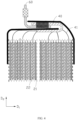
FIG. 1 is a front view of an electrochemical apparatus according to an embodiment of this application. -
FIG. 2 is a cross-sectional view of the electrochemical apparatus shown inFIG. 1 along line II-II with a housing removed. -
FIG. 3 is a cross-sectional view of the electrochemical apparatus shown inFIG. 1 along line III-III with a housing removed. -
FIG. 4 is a cross-sectional view of the electrochemical apparatus shown inFIG. 1 along line IV-IV with a housing removed. -
FIG. 5A is a top view of the electrochemical apparatus shown inFIG. 1 in some other embodiments with a housing removed. -
FIG. 5B is a cross-sectional view of the electrochemical apparatus shown inFIG. 1 in some other embodiments with a housing removed. -
FIG. 6 is a cross-sectional view of the electrochemical apparatus shown inFIG. 1 in still some other embodiments with a housing removed. -
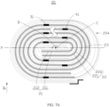
FIG. 7A is a top view of an electrochemical apparatus according to another embodiment of this application. -
FIG. 7B is a cross-sectional view of an electrochemical apparatus according to another embodiment of this application. -
FIG. 8 is a cross-sectional view of an electrochemical apparatus according to yet another embodiment of this application. -
FIG. 9 is a cross-sectional view of an electronic apparatus according to an embodiment of this application. -
Electronic apparatus 1 Housing 10 Body 11 Sealing edge 12 Electrode assembly 20 Side surface 20a, 20b First electrode plate 21 Second electrode plate 22 Separator 23 First tab group 30 First tab 31 Second tab group 40 Second tab 41 First adapting piece 50 Second adapting piece 60 First bonding piece 70 Bending portion 71 Second bonding piece 80 Electrochemical apparatus 100, 200, and 300 First section 201 Second section 202 First bending section 203 Second bending section 204 First current collector 211 First active material layer 212 Second current collector 221 Second active material layer 222 First connecting portion 301 Second connecting portion 302 First sub-portion 3011 Second sub-portion 3012 Third sub-portion 3013 Welding region 3014 Space S Winding direction D First direction D1 Second direction D2 Winding center axis C Winding center plane P - This application will be further described with reference to the accompanying drawings in the following specific embodiments.
- The technical solutions in the embodiments of this application are clearly described below in detail. Apparently, the described embodiments are some rather than all of the embodiments of this application. Unless otherwise defined, all technical and scientific terms used herein shall have the same meanings as commonly understood by those skilled in the art to which this application belongs. The terms used in the specification of this application are merely intended to describe specific embodiments but not intended to constitute any limitation on this application.
- The following describes the embodiments of this application in detail. However, this application may be embodied in many different forms and should not be construed as being limited to the illustrative embodiments set forth herein. Rather, these illustrative embodiments are provided so that this application may be conveyed to those skilled in the art thoroughly and in detail.
- In addition, in the accompanying drawings, sizes or thicknesses of various components and layers may be exaggerated for brevity and clarity. Throughout the application, the same numerical values represent the same elements. As used herein, the term "and/or" includes any and all combinations of one or more of the associated listed items. In addition, it should be understood that when an element A is referred to as being "connected to" an element B, the element A may be directly connected the element B or an intermediate element C may be present therebetween such that the element A and the element B are indirectly connected to each other.
- Further, the use of "may" in describing embodiments of this application refers to "one or more embodiments of this application".
- The terminologies used herein are merely intended to describe specific embodiments but not intended to constitute any limitation on this application. As used herein, the singular forms are intended to include the plural forms as well, unless the context clearly indicates otherwise. It should be further understood that the terms "comprise" or "include" and variations thereof, when used in this specification, specify the presence of stated features, numbers, steps, operations, elements, and/or components but do not preclude the presence or addition of one or more other features, numbers, steps, operations, elements, components, and/or combinations thereof.
- Spatial relation terms such as "above" may be used herein for ease of description to describe the relation between one element or feature and another element (multiple elements) or feature (multiple features) as illustrated in the drawings. It should be understood that spatial relation terms are intended to encompass different orientations of a device or an apparatus in use or operation in addition to the orientations depicted in the drawings. For example, if the device in the drawings is turned over, elements described as being "above" or "over" other elements or features would then be oriented "below" or "beneath" the other elements or features. Thus, the example term "above" may encompass both orientations of being above and below. It should be understood that although the terms first, second, third, or so on may be used herein to describe various elements, components, zones, layers, and/or portions, these elements, components, zones, layers, and/or portions should not be limited by these terms. These terms are used to distinguish one element, component, region, layer, or portion from another element, component, region, layer, or portion. Therefore, a first element, component, region, layer, or portion discussed below may be referred to as a second element, component, region, layer, or portion without departing from the teachings of the illustrative embodiments.
- Referring to
FIG. 1 to FIG. 3 , an embodiment of this application provides anelectrochemical apparatus 100, including ahousing 10, anelectrode assembly 20, afirst tab group 30, asecond tab group 40, afirst adapting piece 50, and asecond adapting piece 60. Theelectrode assembly 20, thefirst tab group 30, and thesecond tab group 40 are disposed inside thehousing 10. - As shown in
FIG. 1 , in some embodiments, thehousing 10 may be a packing bag obtained through packaging using package film (for example, aluminum-plastic film), which means that theelectrochemical apparatus 100 is a pouch cell. Thehousing 10 includes abody 11 for accommodating theelectrode assembly 20 and a sealingedge 12 connected to thebody 11. In some other embodiments, theelectrochemical apparatus 100 is not limited to a pouch cell, but may alternatively be a steel-shell cell or an aluminum-shell cell, which is not limited in this application. - As shown in
FIG. 2 andFIG. 3 , theelectrode assembly 20 includes afirst electrode plate 21, asecond electrode plate 22, and aseparator 23 disposed between thefirst electrode plate 21 and thesecond electrode plate 22. Theseparator 23 is configured to prevent direct contact between thefirst electrode plate 21 and thesecond electrode plate 22, thereby reducing risks of short circuit of theelectrode assembly 20. As shown inFIG. 2 , theelectrode assembly 20 is configured to be a winding structure, that is, thefirst electrode plate 21, theseparator 23, and thesecond electrode plate 22 are stacked in order with the stack wound to form theelectrode assembly 20. Theelectrode assembly 20 has a winding center axis C perpendicular to the plane of paper. The winding direction D is a direction of rotating counterclockwise around the winding center axis C as shown inFIG. 2 . - The
first electrode plate 21 includes a firstcurrent collector 211 and a firstactive material layer 212 disposed on the firstcurrent collector 211. Thesecond electrode plate 22 includes a secondcurrent collector 221 and a secondactive material layer 222 disposed on the secondcurrent collector 221. In some embodiments, thefirst electrode plate 21 may be a negative electrode plate, and thesecond electrode plate 22 may be a positive electrode plate. The firstcurrent collector 211 may be, but is not limited to, a metal foil such as a copper foil or a nickel foil. The secondcurrent collector 221 may be, but is not limited to, a metal foil such as an aluminum foil or a nickel foil. In some other embodiments, the first electrode plate may be a positive electrode plate, and thesecond electrode plate 22 may be a negative electrode plate. - The
first tab group 30 includes M first tabs 31 (M is a natural number greater than 1), where the Mfirst tabs 31 are connected to thefirst electrode plate 21. Specifically, the Mfirst tabs 31 are all connected to the firstcurrent collector 211 of thefirst electrode plate 21. More specifically, the plurality offirst tabs 31 may be integrally formed with the first current collector 211 (which means thefirst tabs 31 are formed by cutting the first current collector 211). Thefirst adapting piece 50 is electrically connected to thefirst tab group 30 and extends out of thehousing 10 at the sealingedge 12 to connect an external component (not shown in the figure). Theelectrode assembly 20 further has a first direction D1 and a second direction D2. The first direction D1 is a thickness direction of theelectrode assembly 20. The second direction D2 is a direction of thefirst tab 31 extending out of thefirst electrode plate 21. For example, the second direction D2 may be a length direction of theelectrode assembly 20. - As shown in
FIG. 2 andFIG. 4 , thesecond tab group 40 includes a plurality ofsecond tabs 41, and thesecond tabs 41 and thefirst tabs 31 have opposite polarities. The plurality ofsecond tabs 41 are connected to thesecond electrode plate 22. Specifically, the plurality ofsecond tabs 41 are connected to the secondcurrent collector 221 of thesecond electrode plate 22. More specifically, the plurality ofsecond tabs 41 may be integrally formed with the secondcurrent collector 221. Thesecond adapting piece 60 is electrically connected to thesecond tab group 40 and extends out of thehousing 10 at the sealingedge 12 to connect an external component. - As shown in
FIG. 2 andFIG. 3 , in the first direction D1, one layer of the firstcurrent collector 211 and the firstactive material layer 212 disposed on the surface of the firstcurrent collector 211 are defined as one layer of thefirst electrode plate 21. Then, theelectrode assembly 20 includes N layers of the first electrode plate 21 (N is a natural number greater than 1), N being greater than M. For simplicity,FIG. 2 andFIG. 3 may only illustratively show partial layers of thefirst electrode plate 21 in theelectrode assembly 20 while the other layers of thefirst electrode plate 21 are omitted. Therefore, it can be understood that the actual number of layers of thefirst electrode plate 21 is not limited to that shown in drawings. Similarly, the layer number of thesecond electrode plate 22 is also not limited to that shown in the drawings. The Mfirst tabs 31 are connected each to thefirst electrode plate 21. In other words, the Mfirst tabs 31 are connected to M layers in N layers of thefirst electrode plate 21 respectively, and in the N layers of thefirst electrode plate 21, the other (N minus M) layers of thefirst electrode plate 21 are not connected to any of thefirst tabs 31. A plane passing through the winding center axis C of theelectrode assembly 20 and perpendicular to the first direction D1 is defined as a winding center plane P. In the first direction D1, the Mfirst tabs 31 are disposed on two sides of the winding center plane P. - Specifically, as shown in
FIG. 2 , in the winding direction D, theelectrode assembly 20 includes afirst section 201, afirst bending section 203, asecond section 202, and asecond bending section 204 that are connected in sequence. In some embodiments, thefirst section 201 and thesecond section 202 may be flat and straight sections arranged in parallel. In some other embodiments, thefirst section 201 and thesecond section 202 may alternatively be bending sections. This is not limited in this application. The winding center plane P is located between thefirst section 201 and thesecond section 202. Therefore, the Mfirst tabs 31 being disposed on the two sides of the winding center plane P means that part of the Mfirst tabs 31 are connected to thefirst electrode plate 21 at thefirst section 201, and the other part of the Mfirst tabs 31 are connected to thefirst electrode plate 21 at thesecond section 202. - More specifically, when N/2<M<N, the M
first tabs 31 may be distributed arbitrarily on the two sides of the winding center plane P. When 2≤M≤N/2, the number offirst tabs 31 located on one side of the winding center plane P is greater than or equal to 1, and the number offirst tabs 31 located on the other side of the winding center plane P is greater than or equal to 1. - As shown in
FIG. 3 , thefirst tab group 30 includes a first connectingportion 301 and a second connectingportion 302. The first connectingportion 301 is connected to thefirst adapting piece 50, and the second connectingportion 302 is connected between thefirst electrode plate 21 and the first connectingportion 301. The Mfirst tabs 31 are stacked to form the first connectingportion 301. In some embodiments, at least two of the Mfirst tabs 31 are stacked in mutual contact, and may be regarded as a part of the first connectingportion 301. Part of thefirst tabs 31 at the second connectingportion 302 are connected to a side of the first connectingportion 301 facing theelectrode assembly 20. - A structure of the
second tab group 40 may be similar to that of thefirst tab group 30, and therefore is not further described. - Straight-out tabs take up space at the head of the electrode assembly, reducing energy density of the electrochemical apparatus. Therefore, before being welded to the adapting piece, the tabs need to be bent. For an electrochemical apparatus having a half tab structure (each turn of the electrode plate is connected to only one tab; for example, only the first electrode plate at the first section of the electrochemical apparatus is connected to first tabs), when an adapting piece is required to be inserted into the housing to a preset position so as to be welded to a bent tab, the bent tab is apt to inversely insert towards the electrode assembly and into the electrode assembly under the action of the adapting piece, causing short circuit and even smoke and fire during subsequent use, thereby degrading use safety of the electrochemical apparatus. An electrochemical apparatus having a full tab structure (each layer of the electrode plate is connected to one tab) helps increase the charge-discharge rate, but also increases difficulties of tab bending and welding, making a manufacturing process more costly.
- In this application, one turn means a turn of the
electrode assembly 20 along the winding direction D starting from a point thereof as a starting end and reaching another point as a terminating end, where the terminating end, the starting end, and the center of the turn are in one straight line and the starting end is located between the terminating end and the center of the turn. One turn forms two layers, which means one turn of thefirst electrode plate 21 includes two layers of thefirst electrode plate 21. - In this application, the number M of
first tabs 31 is set to be smaller than the layer number N of thefirst electrode plate 21, helping reduce difficulties of tab bending and welding, thereby simplifying a manufacturing process. In addition, the Mfirst tabs 31 are connected to M layers in the N layers of thefirst electrode plate 21 respectively, where on the basis that thefirst tabs 31 are disposed on the two sides of the winding center plane P, the number M offirst tabs 31 may be changed as required. Therefore, internal resistance of the electrode plate may be adjusted to make theelectrochemical apparatus 100 meet the requirements of different charge-discharge rates. Furthermore, because part of thefirst tabs 31 at the second connectingportion 302 are connected to the side of the first connectingportion 301 facing theelectrode assembly 20, owing to a limiting function of that part offirst tabs 31, the first connectingportion 301 has a more stable position in the second direction D2 and is not apt to inversely insert under the action of thefirst adapting piece 50 when thefirst adapting piece 50 is inserted into thehousing 10. Therefore, contact short circuit due to a tab being inversely inserted may be alleviated, improving safety of theelectrochemical apparatus 100. Furthermore, an insulating adhesive layer in the prior art disposed for preventing inversely inserted tabs from contacting an end surface of the electrode assembly may be saved to decrease the cost. - As shown in
FIG. 3 , in some embodiments, the first connectingportion 301 forms a U-shaped structure. Thefirst portion 301 includes afirst sub-portion 3011, asecond sub-portion 3012 opposite to thefirst sub-portion 3011, and athird sub-portion 3013 bent and connected between thefirst sub-portion 3011 and thesecond sub-portion 3012. The first connectingportion 3011 is connected to thefirst adapting piece 50, and the second connectingportion 3012 is connected to the second connectingportion 302. The first connectingportion 301 delimits a space S with an opening facing thefirst adapting piece 50. Thefirst adapting piece 50 is at least partly disposed inside the space S delimited by the U-shaped structure, and may be fixed to thefirst sub-portion 3011 by welding. - As shown in
FIG. 3 , furthermore, in some embodiments, in the first direction D1, layers of thefirst electrode plate 21 connected to thefirst tabs 31 and layers of thefirst electrode plate 21 not connected to any of thefirst tabs 31 are alternately arranged. In other words, the number M offirst tabs 31 is N/2 rounded to the nearest whole number, where the number offirst tabs 31 is substantially the same as the number of first tabs of an electrochemical apparatus having a half tab structure. Compared with an electrochemical apparatus having a half tab structure, N layers of thefirst electrode plate 21 being alternatively provided with afirst tab 31 makes part of thefirst tabs 31 disposed on the side of the first connectingportion 301 facing theelectrode assembly 20, and owing to the limiting function of that part offirst tabs 31, risks of contact short circuit due to the first connectingportion 301 being inversely inserted are reduced and safety is improved. Also, because the number offirst tabs 31 is the same as the number of first tabs of an electrochemical apparatus having a half tab structure, the number offirst tabs 31 added to ensure safety is reduced, where the additional first tabs cause difficulties in tab bending and welding in the manufacturing process. - Referring to
FIG. 5A andFIG. 5B , in some other embodiments, the number M offirst tabs 31 is greater than N/2, where thefirst tabs 31 may be connected to any M layers in the N layers of theelectrode plate 21. In other words, the number M offirst tabs 31 may be increased as required. Therefore, compared with the case that layers of thefirst electrode plate 21 connected to thefirst tabs 31 and layers of thefirst electrode plate 21 not connected to any of thefirst tabs 31 are alternately arranged, this may further reduce internal resistance of thefirst electrode plate 21, increasing the charge-discharge rate of theelectrochemical apparatus 100. - As shown in
FIG. 3 , in some embodiments, in the N layers of thefirst electrode plate 21, the two outermost layers of thefirst electrode plate 21 are each connected to afirst tab 31. Theelectrochemical apparatus 100 further includes afirst bonding piece 70 and asecond bonding piece 80. Thefirst bonding piece 70 is bonded to a side of thefirst sub-portion 3011 facing opposite to theelectrode assembly 20 and to aside surface 20a of theelectrode assembly 20 in the first direction D1. In some embodiments, theside surface 20a of theelectrode assembly 20 may be thefirst electrode plate 21, or theseparator 23, or another bonding piece (not shown in the figure). Thesecond bonding piece 80 is bonded to a side of thesecond sub-portion 3012 facing opposite to theelectrode assembly 20 and to theother side surface 20b of theelectrode assembly 20 in the first direction D1. In some embodiments, theside surface 20b of theelectrode assembly 20 may be thefirst electrode plate 21, or theseparator 23, or another bonding piece (not shown in the figure). In the first direction D1, the second connectingportion 302 is located between thefirst bonding piece 70 and thesecond bonding piece 80. It can be understood that burrs may be produced when the firstcurrent collector 211 is cut to form thefirst tabs 31, and welding marks may also be produced when the first connectingportion 301 and thefirst adapting piece 50 are welded. The foregoing burrs and welding marks may pierce thehousing 10, leading to short circuit or electrolyte leakage. Providing thefirst bonding piece 70 and thesecond bonding piece 80 may reduce risks of short circuit or electrolyte leakage caused by thehousing 10 being pierced by burrs or welding marks of the first connectingportion 301. Thefirst bonding piece 70 and/or thesecond bonding piece 80 may be an insulating tape. - Further, in some embodiments, in the first direction D1, width of the
first bonding piece 70 is greater than that of the first connectingportion 301. In some embodiments, a difference in width between thefirst bonding piece 70 and the first connectingportion 301 is 1 mm to 50 mm. Further, in some embodiments, in the first direction D1, width of thesecond bonding piece 80 is greater than that of the first connectingportion 301. In some embodiments, a difference in width between thesecond bonding piece 80 and the first connectingportion 301 is 1 mm to 50 mm. In some embodiments, in the second direction D2, length of thefirst bonding piece 70 bonded to theside surface 20a of theelectrode assembly 20 is not less than 1 mm, making thefirst bonding piece 70 stably bonded to theelectrode assembly 20. In some embodiments, in the second direction D2, length of thesecond bonding piece 80 bonded to theside surface 20b of theelectrode assembly 20 is not less than 1 mm, making thesecond bonding piece 80 stably bonded to thefirst electrode plate 21. In some embodiments, in the second direction D2, length of thefirst bonding piece 70 beyond an edge of theelectrode assembly 20 is not less than 2 mm, making thefirst bonding piece 70 stably bonded to the first connectingportion 301. In some embodiments, in the second direction D2, length of thesecond bonding piece 80 beyond the edge of theelectrode assembly 20 is not less than 2 mm, making thefirst bonding piece 80 stably bonded to the first connectingportion 301. It can be understood that to fully decrease direct contact between thefirst electrode plate 21 and thesecond electrode plate 22, in the second direction D2, an edge of theseparator 23 exceeds edges of thefirst electrode plate 21 and thesecond electrode plate 22. Therefore, in the second direction D2, the edge of theelectrode assembly 20 is typically the edge of theseparator 23. - Referring to
FIG. 6 , in some other embodiments, the Mfirst tabs 31 may be welded together to form awelding region 3014 at thesecond sub-portion 3012. It can be understood that if the Mfirst tabs 31 are not fixed together at the first connectingportion 301, when thefirst adapting piece 50 is inserted into thehousing 10, thefirst tabs 31 at the first connectingportion 301 are apt to separate from each other under the action of thefirst adapting piece 50. In this application, because the Mfirst tabs 31 are fixed at thewelding region 3014 of thesecond sub-portion 3012 by welding, risks may be further reduced that the first connectingportion 301 is inversely inserted because the first tabs 31 (for example, thefirst tabs 31 on the right side in the first direction D1 inFIG. 6 ) at thesecond sub-portion 3012 are separated from each other, further improving safety of theelectrochemical apparatus 100. In some embodiments, thewelding region 3014 may be disposed at an end of thesecond sub-portion 3012 close to thethird sub-portion 3013. - Referring to
FIG. 7A andFIG. 7B , another embodiment of this application further provides anelectrochemical apparatus 200. Theelectrochemical apparatus 200 differs from theelectrochemical apparatus 100 in that, in the first direction D1, in the N layers of thefirst electrode plate 21, one outermost layer of thefirst electrode plate 21 is connected to one of thefirst tabs 31, and another outermost layer of thefirst electrode plate 21 is not connected to any of thefirst tabs 31. - In this case, the
first bonding piece 70 is bonded to a side of thefirst sub-portion 3011 facing opposite to theelectrode assembly 20. In the first direction D1, thefirst bonding piece 70 is also disposed between two adjacent layers of the electrode plate. Thesecond bonding piece 80 is bonded to a side of thesecond sub-portion 3012 facing opposite to theelectrode assembly 20 and to aside surface 20b of theelectrode assembly 20 in the first direction D1. In the first direction D1, the second connectingportion 302 is located between thefirst bonding piece 70 and thesecond bonding piece 80. In this case, thefirst bonding piece 70 and thesecond bonding piece 80 may also reduce risks of short circuit or electrolyte leakage caused by thehousing 10 being pierced by burrs of the first connectingportion 301. Thefirst bonding piece 70 includes a bendingportion 71, where the bendingportion 71 is disposed on a side of thesecond sub-portion 3012 facing theelectrode assembly 20. Therefore, the bendingportion 71 also has a limiting function in a second direction D2 on the first connectingportion 301 to further reduce the risk of the contact short circuit caused by the inverse insertion of the first connectingportion 301. In addition, in the first direction D1, thefirst bonding piece 70 is also disposed between two adjacent layers of the electrode plate, reducing the thickness in thefirst direction D 1 and increasing energy density. - As shown in
FIG. 7B , furthermore, each layer of afirst electrode plate 21 disposed between afirst bonding piece 70 and asecond bonding piece 80 is connected to afirst tab 31. In this manner, the number of thefirst tab 31 may be further increased, increasing a charge-discharge rate of anelectrochemical apparatus 100. - In some embodiments, the M
first tabs 31 are welded together to form awelding region 3014 at thesecond sub-portion 3012, so that the risk may be reduced that the first connectingportion 301 is inversely inserted because thefirst tabs 31 of thesecond sub-portion 3012 are separated from each other. The bendingportion 71 is disposed on a side of thewelding region 3014 facing theelectrode assembly 20. - Referring to
FIG. 8 , yet another embodiment of this application further provides anelectrochemical apparatus 300. Theelectrochemical apparatus 300 differs from theelectrochemical apparatus 100 in that the first connectingportion 301 is not a U-shaped structure, but runs in the second direction D2 as a whole. During manufacturing, it is only required to bend thefirst tab group 30 at a joint between the first connectingportion 301 and a second connectingportion 302, and the first connectingportion 301 itself does not need to be bent, helping simplify the manufacturing process. - The
electrochemical apparatus electrochemical apparatus electrochemical apparatus - Referring to
FIG. 9 , an embodiment of this application further provides anelectronic apparatus 1. Theelectronic apparatus 1 includes the electrochemical apparatus 100 (or theelectrochemical apparatus 200 or 300). Theelectrochemical apparatus electronic apparatuses 1 in various fields. In an embodiment, theelectronic apparatus 1 of this application may be, but is not limited to, a notebook computer, a pen-input computer, a mobile computer, an electronic book player, a portable telephone, a portable fax machine, a portable copier, a portable printer, a stereo headset, a video recorder, a liquid crystal display television, a portable cleaner, a portable CD player, a mini-disc, a transceiver, an electronic notebook, a calculator, a memory card, a portable recorder, a radio, a standby power source, a motor, an automobile, a motorcycle, a motorized bicycle, a bicycle, a lighting appliance, a toy, a game console, a timepiece, an electric tool, a flash lamp, a camera, a large household battery, a lithium-ion capacitor, or the like. - Finally, it should be noted that the foregoing embodiments are merely intended to describe the technical solutions of this application, but not to constitute any limitation. Although this application is described in detail with reference to preferred embodiments, persons of ordinary skill in the art should understand that modifications or equivalent replacements can be made to the technical solutions of this application, without departing from the scope of the technical solutions of this application.
Claims (13)
- An electrochemical apparatus, comprising: a housing, an electrode assembly disposed inside the housing, a first tab group, and a first adapting piece electrically connected to the first tab group and extending out from the housing; wherein the electrode assembly is configured to be a winding structure and comprises a first electrode plate, the first tab group comprises M first tabs; characterized in that,a thickness direction of the electrode assembly is defined as a first direction, wherein in the first direction, the electrode assembly comprises N layers of the first electrode plate, N being greater than M, and the M first tabs are each connected to the first electrode plate; a plane passing through a winding center axis of the electrode assembly and perpendicular to the first direction is defined as a winding center plane, wherein in the first direction, the M first tabs are disposed on two sides of the winding center plane; andthe first tab group comprises a first connecting portion connected to the first adapting piece and a second connecting portion connected to the first electrode plate; wherein the M first tabs are stacked to form the first connecting portion, and part of the first tabs at the second connecting portion are connected to a side of the first connecting portion facing the electrode assembly.
- The electrochemical apparatus according to claim 1, characterized in that, in the first direction, layers of the first electrode plate connected to the first tabs and layers of the first electrode plate not connected to any of the first tabs are alternately arranged.
- The electrochemical apparatus according to claim 1, characterized in that, the first connecting portion forms a U-shaped structure, and the first connecting portion comprises a first sub-portion, a second sub-portion, and a third sub-portion; wherein the first sub-portion is connected to the first adapting piece, the second sub-portion is connected to the second connecting portion, the third sub-portion is bent and connected between the first sub-portion and the second sub-portion, and the first adapting piece is at least partly disposed in a space delimited by the U-shaped structure.
- The electrochemical apparatus according to claim 3, characterized in that, in the first direction, in the N layers of the first electrode plate, one outermost layer of the first electrode plate is connected to one of the first tabs, and another outermost layer of the first electrode plate is not connected to any of the first tabs.
- The electrochemical apparatus according to claim 4, characterized in that, the electrochemical apparatus (100, 200, or 300) further comprising:a first bonding piece bonded to a side of the first sub-portion facing opposite to the electrode assembly; anda second bonding piece bonded to a side of the second sub-portion facing opposite to the electrode assembly and to a side surface of the electrode assembly in the first direction; andin the first direction, the first bonding piece is disposed between two adjacent layers of the first electrode plate, and the second connecting portion is located between the first bonding piece and the second bonding piece; wherein the first bonding piece comprises a bending portion disposed on a side of the second sub-portion facing the electrode assembly.
- The electrochemical apparatus according to claim 5, characterized in that, the M first tabs are welded together to form a welding region at the second sub-portion, and the bending portion is disposed on a side of the welding region facing the electrode assembly.
- The electrochemical apparatus according to claim 5, characterized in that, each layer of the first electrode plate disposed between the first bonding piece and the second bonding piece is connected to one of the first tabs.
- The electrochemical apparatus according to claim 3, characterized in that, two outermost layers of the first electrode plate in the N layers of the first electrode plate are each connected to one of the first tabs.
- The electrochemical apparatus according to claim 8, characterized in that, the electrochemical apparatus (100, 200, or 300) further comprising:a first bonding piece bonded to a side of the first sub-portion facing opposite to the electrode assembly and to a side surface of the electrode assembly in the first direction; anda second bonding piece bonded to a side of the second sub-portion facing opposite to the electrode assembly and to another side surface of the electrode assembly in the first direction; wherein in the first direction, the second connecting portion is located between the first bonding piece and the second bonding piece.
- The electrochemical apparatus according to claim 9, characterized in that, the M first tabs are welded together to form a welding region at the second sub-portion.
- The electrochemical apparatus according to claim 5 or 9, characterized in that, at least one of the first bonding piece or the second bonding piece is an insulating tape.
- The electrochemical apparatus according to claim 1, characterized in that, the first electrode plate comprises a current collector and an active material layer disposed on a surface of the current collector, wherein the first tab and the current collector are integrally formed.
- An electronic apparatus, comprising the electrochemical apparatus according to any one of claims 1 to 12.
Applications Claiming Priority (2)
| Application Number | Priority Date | Filing Date | Title |
|---|---|---|---|
| CN202110698548.8A CN113437444B (en) | 2021-06-23 | 2021-06-23 | Electrochemical device and electronic device |
| PCT/CN2022/098472 WO2022267925A1 (en) | 2021-06-23 | 2022-06-13 | Electrochemical device and electronic device |
Publications (1)
| Publication Number | Publication Date |
|---|---|
| EP4207477A1 true EP4207477A1 (en) | 2023-07-05 |
Family
ID=77753626
Family Applications (1)
| Application Number | Title | Priority Date | Filing Date |
|---|---|---|---|
| EP22827421.3A Pending EP4207477A1 (en) | 2021-06-23 | 2022-06-13 | Electrochemical device and electronic device |
Country Status (5)
| Country | Link |
|---|---|
| US (1) | US20230238667A1 (en) |
| EP (1) | EP4207477A1 (en) |
| JP (1) | JP2023535128A (en) |
| CN (2) | CN117276816A (en) |
| WO (1) | WO2022267925A1 (en) |
Families Citing this family (11)
| Publication number | Priority date | Publication date | Assignee | Title |
|---|---|---|---|---|
| CN117276816A (en) * | 2021-06-23 | 2023-12-22 | 东莞新能安科技有限公司 | Electrochemical device and electronic device |
| CN113948711A (en) * | 2021-10-15 | 2022-01-18 | 东莞新能安科技有限公司 | Electrochemical device, battery pack, and electronic device |
| CN113972448B (en) * | 2021-10-19 | 2022-08-09 | 东莞新能安科技有限公司 | Electrochemical device and electronic device comprising same |
| WO2023123410A1 (en) * | 2021-12-31 | 2023-07-06 | 东莞新能源科技有限公司 | Battery cell, battery, and electrical device |
| WO2023141776A1 (en) * | 2022-01-25 | 2023-08-03 | 东莞新能安科技有限公司 | Battery and electronic device comprising same |
| CN114614210B (en) * | 2022-03-18 | 2024-02-20 | 东莞新能安科技有限公司 | Electrochemical device, battery module, and electronic apparatus |
| WO2023184267A1 (en) * | 2022-03-30 | 2023-10-05 | 宁德新能源科技有限公司 | Connecting device, battery, and battery manufacturing method |
| CN114420993B (en) * | 2022-03-30 | 2022-07-05 | 宁德新能源科技有限公司 | Electrochemical device and electronic apparatus |
| CN114665228B (en) * | 2022-03-31 | 2024-05-07 | 东莞新能安科技有限公司 | Electrochemical device and electronic device |
| CN114649559A (en) * | 2022-03-31 | 2022-06-21 | 东莞新能安科技有限公司 | Electrochemical device and electronic device |
| CN115064843A (en) * | 2022-07-20 | 2022-09-16 | 宁德新能源科技有限公司 | Battery and power consumption device thereof |
Family Cites Families (11)
| Publication number | Priority date | Publication date | Assignee | Title |
|---|---|---|---|---|
| CN200979897Y (en) * | 2006-10-31 | 2007-11-21 | 广州丰江电池新技术有限公司 | A winding type electrical core of a lithium battery |
| JP2017050069A (en) * | 2015-08-31 | 2017-03-09 | 株式会社豊田自動織機 | Power storage device |
| CN206490135U (en) * | 2016-12-27 | 2017-09-12 | 宁德新能源科技有限公司 | A kind of takeup type battery core |
| WO2020103014A1 (en) * | 2018-11-21 | 2020-05-28 | 深圳市马力科技有限公司 | Smart battery and lithium battery core thereof |
| CN111403789B (en) * | 2019-01-02 | 2021-12-10 | 东莞新能源科技有限公司 | Electrode assembly and battery |
| JP7150672B2 (en) * | 2019-07-19 | 2022-10-11 | 本田技研工業株式会社 | Secondary battery and manufacturing method thereof |
| CN111313102A (en) * | 2020-03-03 | 2020-06-19 | 宁德新能源科技有限公司 | Battery cell, electrochemical device comprising same and electronic device |
| CN212810347U (en) * | 2020-06-30 | 2021-03-26 | 宁德新能源科技有限公司 | Electrochemical device and electronic device including the same |
| CN113097660A (en) * | 2021-03-30 | 2021-07-09 | 东莞新能安科技有限公司 | Electrochemical device and power utilization device using same |
| WO2022205141A1 (en) * | 2021-03-31 | 2022-10-06 | 宁德新能源科技有限公司 | Electrode assembly, electrochemical device, and electrical apparatus |
| CN117276816A (en) * | 2021-06-23 | 2023-12-22 | 东莞新能安科技有限公司 | Electrochemical device and electronic device |
-
2021
- 2021-06-23 CN CN202311302868.2A patent/CN117276816A/en active Pending
- 2021-06-23 CN CN202110698548.8A patent/CN113437444B/en active Active
-
2022
- 2022-06-13 JP JP2022579830A patent/JP2023535128A/en active Pending
- 2022-06-13 EP EP22827421.3A patent/EP4207477A1/en active Pending
- 2022-06-13 WO PCT/CN2022/098472 patent/WO2022267925A1/en unknown
-
2023
- 2023-03-30 US US18/193,180 patent/US20230238667A1/en active Pending
Also Published As
| Publication number | Publication date |
|---|---|
| US20230238667A1 (en) | 2023-07-27 |
| CN113437444A (en) | 2021-09-24 |
| CN113437444B (en) | 2023-10-27 |
| WO2022267925A1 (en) | 2022-12-29 |
| JP2023535128A (en) | 2023-08-16 |
| CN117276816A (en) | 2023-12-22 |
Similar Documents
| Publication | Publication Date | Title |
|---|---|---|
| EP4207477A1 (en) | Electrochemical device and electronic device | |
| EP4109617A2 (en) | Electrochemical apparatus and electronic apparatus | |
| US11303000B2 (en) | Electrode assembly and secondary battery including the same | |
| US7201998B2 (en) | Pouch-type lithium secondary battery | |
| US9972868B2 (en) | Curved electrode stack and battery pack including the same | |
| US20050003264A1 (en) | Jelly-roll type electrode assembly and secondary battery employing the same | |
| JP2016502742A (en) | Electrode assembly including round corners | |
| US20230015190A1 (en) | Battery cell and electronic device | |
| US20240014484A1 (en) | Electrochemical apparatus, preparation method thereof, and electronic apparatus | |
| US20230261335A1 (en) | Battery and electronic device having same | |
| US20240030528A1 (en) | Cell and electric apparatus | |
| KR20040054113A (en) | Pouched-type case and lithium secondary battery applying the same | |
| KR100731436B1 (en) | Pouch type Lithium Secondary Battery | |
| CN115347291B (en) | Electrochemical device and electronic device | |
| CN215497001U (en) | Battery pack and electric equipment | |
| CN113948711A (en) | Electrochemical device, battery pack, and electronic device | |
| CN114586231A (en) | Battery and electric device with same | |
| CN113924674A (en) | Secondary battery | |
| CN214477543U (en) | Battery cell and power utilization device | |
| US20220407185A1 (en) | Rechargeable secondary battery | |
| CN215266413U (en) | Battery cell, battery and electric equipment | |
| US20240079737A1 (en) | Electrode assembly, electrochemical apparatus, and electric device | |
| US20220416331A1 (en) | Battery and electric device containing same | |
| EP4160793A1 (en) | Pouch type rechargeable-battery | |
| CN117996369A (en) | Secondary battery and electronic device |
Legal Events
| Date | Code | Title | Description |
|---|---|---|---|
| STAA | Information on the status of an ep patent application or granted ep patent |
Free format text: STATUS: THE INTERNATIONAL PUBLICATION HAS BEEN MADE |
|
| PUAI | Public reference made under article 153(3) epc to a published international application that has entered the european phase |
Free format text: ORIGINAL CODE: 0009012 |
|
| STAA | Information on the status of an ep patent application or granted ep patent |
Free format text: STATUS: REQUEST FOR EXAMINATION WAS MADE |
|
| 17P | Request for examination filed |
Effective date: 20230330 |
|
| AK | Designated contracting states |
Kind code of ref document: A1 Designated state(s): AL AT BE BG CH CY CZ DE DK EE ES FI FR GB GR HR HU IE IS IT LI LT LU LV MC MK MT NL NO PL PT RO RS SE SI SK SM TR |