EP4583174A1 - Electrode plate, electrode body, and battery - Google Patents
Electrode plate, electrode body, and battery Download PDFInfo
- Publication number
- EP4583174A1 EP4583174A1 EP23859754.6A EP23859754A EP4583174A1 EP 4583174 A1 EP4583174 A1 EP 4583174A1 EP 23859754 A EP23859754 A EP 23859754A EP 4583174 A1 EP4583174 A1 EP 4583174A1
- Authority
- EP
- European Patent Office
- Prior art keywords
- electrode plate
- principal surface
- electrode
- identification indication
- active material
- Prior art date
- Legal status (The legal status is an assumption and is not a legal conclusion. Google has not performed a legal analysis and makes no representation as to the accuracy of the status listed.)
- Pending
Links
Images



Classifications
-
- H—ELECTRICITY
- H01—ELECTRIC ELEMENTS
- H01G—CAPACITORS; CAPACITORS, RECTIFIERS, DETECTORS, SWITCHING DEVICES, LIGHT-SENSITIVE OR TEMPERATURE-SENSITIVE DEVICES OF THE ELECTROLYTIC TYPE
- H01G2/00—Details of capacitors not covered by a single one of groups H01G4/00-H01G11/00
- H01G2/24—Distinguishing marks, e.g. colour coding
-
- H—ELECTRICITY
- H01—ELECTRIC ELEMENTS
- H01G—CAPACITORS; CAPACITORS, RECTIFIERS, DETECTORS, SWITCHING DEVICES, LIGHT-SENSITIVE OR TEMPERATURE-SENSITIVE DEVICES OF THE ELECTROLYTIC TYPE
- H01G11/00—Hybrid capacitors, i.e. capacitors having different positive and negative electrodes; Electric double-layer [EDL] capacitors; Processes for the manufacture thereof or of parts thereof
- H01G11/04—Hybrid capacitors
- H01G11/06—Hybrid capacitors with one of the electrodes allowing ions to be reversibly doped thereinto, e.g. lithium ion capacitors [LIC]
-
- H—ELECTRICITY
- H01—ELECTRIC ELEMENTS
- H01G—CAPACITORS; CAPACITORS, RECTIFIERS, DETECTORS, SWITCHING DEVICES, LIGHT-SENSITIVE OR TEMPERATURE-SENSITIVE DEVICES OF THE ELECTROLYTIC TYPE
- H01G11/00—Hybrid capacitors, i.e. capacitors having different positive and negative electrodes; Electric double-layer [EDL] capacitors; Processes for the manufacture thereof or of parts thereof
- H01G11/66—Current collectors
- H01G11/70—Current collectors characterised by their structure
-
- H—ELECTRICITY
- H01—ELECTRIC ELEMENTS
- H01M—PROCESSES OR MEANS, e.g. BATTERIES, FOR THE DIRECT CONVERSION OF CHEMICAL ENERGY INTO ELECTRICAL ENERGY
- H01M10/00—Secondary cells; Manufacture thereof
- H01M10/05—Accumulators with non-aqueous electrolyte
- H01M10/052—Li-accumulators
- H01M10/0525—Rocking-chair batteries, i.e. batteries with lithium insertion or intercalation in both electrodes; Lithium-ion batteries
-
- H—ELECTRICITY
- H01—ELECTRIC ELEMENTS
- H01M—PROCESSES OR MEANS, e.g. BATTERIES, FOR THE DIRECT CONVERSION OF CHEMICAL ENERGY INTO ELECTRICAL ENERGY
- H01M10/00—Secondary cells; Manufacture thereof
- H01M10/05—Accumulators with non-aqueous electrolyte
- H01M10/058—Construction or manufacture
- H01M10/0587—Construction or manufacture of accumulators having only wound construction elements, i.e. wound positive electrodes, wound negative electrodes and wound separators
-
- H—ELECTRICITY
- H01—ELECTRIC ELEMENTS
- H01M—PROCESSES OR MEANS, e.g. BATTERIES, FOR THE DIRECT CONVERSION OF CHEMICAL ENERGY INTO ELECTRICAL ENERGY
- H01M10/00—Secondary cells; Manufacture thereof
- H01M10/42—Methods or arrangements for servicing or maintenance of secondary cells or secondary half-cells
- H01M10/48—Accumulators combined with arrangements for measuring, testing or indicating the condition of cells, e.g. the level or density of the electrolyte
- H01M10/488—Cells or batteries combined with indicating means for external visualization of the condition, e.g. by change of colour or of light density
-
- H—ELECTRICITY
- H01—ELECTRIC ELEMENTS
- H01M—PROCESSES OR MEANS, e.g. BATTERIES, FOR THE DIRECT CONVERSION OF CHEMICAL ENERGY INTO ELECTRICAL ENERGY
- H01M4/00—Electrodes
- H01M4/02—Electrodes composed of, or comprising, active material
- H01M4/13—Electrodes for accumulators with non-aqueous electrolyte, e.g. for lithium-accumulators; Processes of manufacture thereof
-
- H—ELECTRICITY
- H01—ELECTRIC ELEMENTS
- H01M—PROCESSES OR MEANS, e.g. BATTERIES, FOR THE DIRECT CONVERSION OF CHEMICAL ENERGY INTO ELECTRICAL ENERGY
- H01M4/00—Electrodes
- H01M4/02—Electrodes composed of, or comprising, active material
- H01M4/64—Carriers or collectors
- H01M4/70—Carriers or collectors characterised by shape or form
-
- H—ELECTRICITY
- H01—ELECTRIC ELEMENTS
- H01M—PROCESSES OR MEANS, e.g. BATTERIES, FOR THE DIRECT CONVERSION OF CHEMICAL ENERGY INTO ELECTRICAL ENERGY
- H01M50/00—Constructional details or processes of manufacture of the non-active parts of electrochemical cells other than fuel cells, e.g. hybrid cells
- H01M50/10—Primary casings; Jackets or wrappings
- H01M50/102—Primary casings; Jackets or wrappings characterised by their shape or physical structure
- H01M50/107—Primary casings; Jackets or wrappings characterised by their shape or physical structure having curved cross-section, e.g. round or elliptic
-
- H—ELECTRICITY
- H01—ELECTRIC ELEMENTS
- H01M—PROCESSES OR MEANS, e.g. BATTERIES, FOR THE DIRECT CONVERSION OF CHEMICAL ENERGY INTO ELECTRICAL ENERGY
- H01M10/00—Secondary cells; Manufacture thereof
- H01M10/04—Construction or manufacture in general
- H01M10/0431—Cells with wound or folded electrodes
-
- H—ELECTRICITY
- H01—ELECTRIC ELEMENTS
- H01M—PROCESSES OR MEANS, e.g. BATTERIES, FOR THE DIRECT CONVERSION OF CHEMICAL ENERGY INTO ELECTRICAL ENERGY
- H01M50/00—Constructional details or processes of manufacture of the non-active parts of electrochemical cells other than fuel cells, e.g. hybrid cells
- H01M50/50—Current conducting connections for cells or batteries
- H01M50/572—Means for preventing undesired use or discharge
- H01M50/584—Means for preventing undesired use or discharge for preventing incorrect connections inside or outside the batteries
- H01M50/59—Means for preventing undesired use or discharge for preventing incorrect connections inside or outside the batteries characterised by the protection means
- H01M50/595—Tapes
-
- Y—GENERAL TAGGING OF NEW TECHNOLOGICAL DEVELOPMENTS; GENERAL TAGGING OF CROSS-SECTIONAL TECHNOLOGIES SPANNING OVER SEVERAL SECTIONS OF THE IPC; TECHNICAL SUBJECTS COVERED BY FORMER USPC CROSS-REFERENCE ART COLLECTIONS [XRACs] AND DIGESTS
- Y02—TECHNOLOGIES OR APPLICATIONS FOR MITIGATION OR ADAPTATION AGAINST CLIMATE CHANGE
- Y02E—REDUCTION OF GREENHOUSE GAS [GHG] EMISSIONS, RELATED TO ENERGY GENERATION, TRANSMISSION OR DISTRIBUTION
- Y02E60/00—Enabling technologies; Technologies with a potential or indirect contribution to GHG emissions mitigation
- Y02E60/10—Energy storage using batteries
-
- Y—GENERAL TAGGING OF NEW TECHNOLOGICAL DEVELOPMENTS; GENERAL TAGGING OF CROSS-SECTIONAL TECHNOLOGIES SPANNING OVER SEVERAL SECTIONS OF THE IPC; TECHNICAL SUBJECTS COVERED BY FORMER USPC CROSS-REFERENCE ART COLLECTIONS [XRACs] AND DIGESTS
- Y02—TECHNOLOGIES OR APPLICATIONS FOR MITIGATION OR ADAPTATION AGAINST CLIMATE CHANGE
- Y02P—CLIMATE CHANGE MITIGATION TECHNOLOGIES IN THE PRODUCTION OR PROCESSING OF GOODS
- Y02P70/00—Climate change mitigation technologies in the production process for final industrial or consumer products
- Y02P70/50—Manufacturing or production processes characterised by the final manufactured product
Definitions
- the present disclosure relates to an electrode plate, an electrode body, and a battery.
- Patent Literature 1 An electrode plate described in Patent Literature 1 includes a band-shaped core body, and active material layers formed on both sides of the core body.
- the core body includes an exposed part to which a current collector lead is connected, and an identification indication part that enables identification of a manufacturing process history is formed on a portion of the exposed part.
- Patent Literature 1 WO 2019/193869
- the identification indication part described in Patent Literature 1 is disposed in a region located toward an end portion of the exposed part (toward one end of the core body in the width direction thereof), as shown in, for example, FIG. 4 of the literature.
- the region located toward the end portion of the exposed part is likely to bend during a process of forming the identification indication part, and it is not easy to accurately form the identification indication part in such a region that is likely to bend. Under such circumstances, it is an object of the present disclosure to accurately form an identification indication part.
- the electrode plate includes: a band-shaped core body having a first principal surface and a second principal surface; and an active material layer formed on each of the first principal surface and the second principal surface, wherein the core body includes a double-side coated part on which the active material layer is formed on each of the first principal surface and the second principal surface, and an exposed part provided continuously with the double-side coated part and on which the active material layer is not formed on at least the first principal surface, and the first principal surface on the exposed part has an identification indication part formed thereon in a region within 90% of an area located toward a center in a width direction of the core body.
- the electrode body includes: a first electrode plate and a second electrode plate that are wound with a separator interposed therebetween, wherein the first electrode plate is the above-described electrode plate.
- the battery includes: the above-described electrode body; and a bottomed tubular exterior can that accommodates the electrode body.
- Embodiments of the electrode plate, the electrode body, and the battery according to the present disclosure will be described below by way of examples. However, the present disclosure is not limited to the examples described below. Although examples of specific numerical values and materials may be given in the following description, other numerical values and materials may be used as long as the effects of the present disclosure can be achieved.
- An electrode plate according to the present disclosure includes a band-shaped core body, and an active material layer.
- an electrode plate for use in a non-aqueous electrolyte secondary battery e.g., a lithium ion secondary battery
- the use of the electrode plate is not limited thereto.
- a power storage device e.g., a lithium ion capacitor
- the core body has a first principal surface and a second principal surface.
- the core body may be, for example, a metal foil made of aluminum, an aluminum alloy, stainless steel, titanium, a titanium alloy, or the like.
- the core body may be, for example, a metal foil made of copper, a copper alloy, nickel, a nickel alloy, or the like.
- the active material layer is formed on each of the first principal surface and the second principal surface of the core body.
- the active material layer is a positive electrode active material layer, and may contain, in addition to a positive electrode active material, a conductive agent, a binder, a thickener, and the like.
- the active material layer is a negative electrode active material layer, and may contain, in addition to a negative electrode active material, a conductive agent, a binder, a thickener, and the like.
- the above-described core body includes a double-side coated part, and an exposed part provided continuously with the double-side coated part.
- the double-side coated part has the active material layer formed on each of the first principal surface and the second principal surface.
- the exposed part does not have the active material layer formed thereon at least on the first principal surface.
- the exposed part may be a single-side coated part on which the active material layer is not formed on the first principal surface while the active material layer is formed on the second principal surface, a double-side exposed part on which the active material layer is not formed on the first principal surface and the second principal surface, or a combination of the single-side coated part and the double-side exposed part.
- the exposed part may be disposed on one end of the core body in the longitudinal direction thereof.
- the identification indication part 28 is disposed in the vicinity of the double-side coated part 25. Specifically, the identification indication part 28 is formed in a region within 30% of an area located toward the double-side coated part 25 (preferably a region within 20% of an area located toward the double-side coated part 25) of the exposed part 26 in the longitudinal direction (the lateral direction in FIG. 5 ) of the core body 22.
- An electrode body including:
- a height dimension of the identification indication part is smaller than a height dimension of the pair of tapes.
- a battery including:
- the present disclosure is applicable to electrode plates, electrode assemblies, and batteries.
Landscapes
- Engineering & Computer Science (AREA)
- Chemical & Material Sciences (AREA)
- Chemical Kinetics & Catalysis (AREA)
- Electrochemistry (AREA)
- General Chemical & Material Sciences (AREA)
- Power Engineering (AREA)
- Manufacturing & Machinery (AREA)
- Materials Engineering (AREA)
- Microelectronics & Electronic Packaging (AREA)
- Battery Electrode And Active Subsutance (AREA)
Abstract
Description
- The present disclosure relates to an electrode plate, an electrode body, and a battery.
- Conventionally, techniques for indicating information on electrode plates included in batteries are known (e.g., Patent Literature 1). An electrode plate described in
Patent Literature 1 includes a band-shaped core body, and active material layers formed on both sides of the core body. The core body includes an exposed part to which a current collector lead is connected, and an identification indication part that enables identification of a manufacturing process history is formed on a portion of the exposed part. - Patent Literature 1:
WO 2019/193869 - However, the identification indication part described in
Patent Literature 1 is disposed in a region located toward an end portion of the exposed part (toward one end of the core body in the width direction thereof), as shown in, for example,FIG. 4 of the literature. The region located toward the end portion of the exposed part is likely to bend during a process of forming the identification indication part, and it is not easy to accurately form the identification indication part in such a region that is likely to bend. Under such circumstances, it is an object of the present disclosure to accurately form an identification indication part. - An aspect of the present disclosure relates to an electrode plate. The electrode plate includes: a band-shaped core body having a first principal surface and a second principal surface; and an active material layer formed on each of the first principal surface and the second principal surface, wherein the core body includes a double-side coated part on which the active material layer is formed on each of the first principal surface and the second principal surface, and an exposed part provided continuously with the double-side coated part and on which the active material layer is not formed on at least the first principal surface, and the first principal surface on the exposed part has an identification indication part formed thereon in a region within 90% of an area located toward a center in a width direction of the core body.
- Another aspect of the present disclosure relates to an electrode body. The electrode body includes: a first electrode plate and a second electrode plate that are wound with a separator interposed therebetween, wherein the first electrode plate is the above-described electrode plate.
- Yet another aspect of the present disclosure relates to a battery. The battery includes: the above-described electrode body; and a bottomed tubular exterior can that accommodates the electrode body.
- According to the present disclosure, it is possible to accurately form an identification indication part.
- While the novel features of the invention are set forth in the appended claims, the invention, both as to organization and content, will be better understood and appreciated, along with other objects and features thereof, from the following detailed description taken in conjunction with the drawings.
-
- [
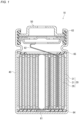
FIG. 1 ] A vertical cross-sectional view schematically showing a battery according toEmbodiment 1. - [
FIG. 2 ] A perspective view schematically showing an electrode body according toEmbodiment 1. - [
FIG. 3 ] Views schematically showing a first electrode plate (electrode plate) according toEmbodiment 1, withFIG. 3(a) showing a plan view, andFIG. 3(b) showing a cross-sectional view taken along the line III-III. - [
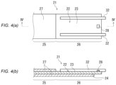
FIG. 4 ] Views schematically showing a first electrode plate (electrode plate) according to Embodiment 2, withFIG. 4(a) showing a plan view, andFIG. 4(b) showing a cross-sectional view taken along the line IV-IV. - [
FIG. 5 ] Views schematically showing a first electrode plate (electrode plate) according to Embodiment 3, withFIG. 5(a) showing a plan view, andFIG. 5(b) showing a cross-sectional view taken along the line V-V - Embodiments of the electrode plate, the electrode body, and the battery according to the present disclosure will be described below by way of examples. However, the present disclosure is not limited to the examples described below. Although examples of specific numerical values and materials may be given in the following description, other numerical values and materials may be used as long as the effects of the present disclosure can be achieved.
- An electrode plate according to the present disclosure includes a band-shaped core body, and an active material layer. Although the following description will be given, taking, as an example, an electrode plate for use in a non-aqueous electrolyte secondary battery (e.g., a lithium ion secondary battery), the use of the electrode plate is not limited thereto. Note that in the present disclosure, a power storage device (e.g., a lithium ion capacitor) in which at least one of a positive electrode and a negative electrode is an electrode that develops a capacity by a Faradaic reaction also falls under the category of secondary batteries.
- The core body has a first principal surface and a second principal surface. When the electrode plate is used as a positive electrode plate, the core body may be, for example, a metal foil made of aluminum, an aluminum alloy, stainless steel, titanium, a titanium alloy, or the like. When the electrode plate is used as a negative electrode plate, the core body may be, for example, a metal foil made of copper, a copper alloy, nickel, a nickel alloy, or the like.
- The active material layer is formed on each of the first principal surface and the second principal surface of the core body. When the electrode plate is used as a positive electrode plate, the active material layer is a positive electrode active material layer, and may contain, in addition to a positive electrode active material, a conductive agent, a binder, a thickener, and the like. When the electrode plate is used as a negative electrode plate, the active material layer is a negative electrode active material layer, and may contain, in addition to a negative electrode active material, a conductive agent, a binder, a thickener, and the like.
- For example, examples of the positive electrode active material that can be used include composite metal oxides of lithium and transition metals such as cobalt, manganese, and nickel. The positive electrode active materials may be used alone or in a combination of two or more. Examples of the negative electrode active material include carbon materials such as natural graphite, spherical or fibrous artificial graphite, non-graphitizable carbon (hard carbon), and graphitizable carbon (soft carbon).
- Carbon black such as acetylene black, Ketjen black, channel black, furnace black, lamp black, and thermal black; conductive fibers such as carbon fibers and metal fibers, and the like can be used as the conductive agent. Various graphites such as natural graphite and artificial graphite can also be used as the conductive agent of the positive electrode.
- The binder is not particularly limited as long as the binder can be dissolved or dispersed in a dispersing medium through kneading. Examples of the binder include a fluorocarbon resin, rubbers, an acrylic polymer or a vinyl polymer (a homopolymer or copolymer of monomers, including, an acrylic monomer such as methyl acrylate and acrylonitrile, and a vinyl monomer such as vinyl acetate). Examples of the fluorocarbon resin include polyvinylidene fluoride, a copolymer of vinylidene fluoride and hexafluoropropylene, and polytetrafluoroethylene. Examples of the rubbers include an acrylic rubber, a modified acrylonitrile rubber, and a styrenebutadiene rubber (SBR). The binders may be used alone or in a combination of two or more. In general, a fluorocarbon resin is preferred as the binder of the positive electrode, and a fluorocarbon resin and rubbers are preferred as the binder of the negative electrode.
- The above-described core body includes a double-side coated part, and an exposed part provided continuously with the double-side coated part. The double-side coated part has the active material layer formed on each of the first principal surface and the second principal surface. The exposed part does not have the active material layer formed thereon at least on the first principal surface. For example, the exposed part may be a single-side coated part on which the active material layer is not formed on the first principal surface while the active material layer is formed on the second principal surface, a double-side exposed part on which the active material layer is not formed on the first principal surface and the second principal surface, or a combination of the single-side coated part and the double-side exposed part. The exposed part may be disposed on one end of the core body in the longitudinal direction thereof.
- The first principal surface of the exposed part has an identification indication part formed thereon in a region within 90% of an area located toward the center in the width direction of the core body (hereinafter also referred to as a region A). The region A can also be regarded as a region of the first principal surface on the exposed part, other than a region in 5% of an area located toward one end and a region in 5% of an area located toward the other end in the width direction of the core body. The region A is less likely to bend during the process of forming the identification indication part, and it is thus possible to accurately form the identification indication part. The identification indication part may be an identification indication part that enables identification of a manufacturing process history. The identification indication part may be, but is not limited to, a QR code (registered trademark), which is a two-dimensional code. For example, the identification indication part may be composed of number, characters, or a combination of numbers and characters, or may be composed of projections, holes, or a combination of projections and holes. The identification indication part may be a one-dimensional code such as a bar code. The identification indication part may be formed, for example, by irradiating the first principal surface of the exposed part with laser.
- The first principal surface on the exposed part may have the identification indication part formed thereon in a region within 80%, 70%, 60%, 50%, 40%, or 30% of an area located toward the center in the width direction of the core body. This enables the identification indication part to be formed even more accurately. Note that a region within X% of an area located toward the center refers to a collection of points that include a central point in the width direction of the core body, and that are symmetrical with respect to the central point in the width direction of the core body.
- The second principal surface on the exposed part may have the active material layer formed thereon at a position at which the identification indication part is formed. That is, a region of the exposed part in which the identification indication part is formed may be the above-described single-side coated part. With this configuration, the strength of the region in which the identification indication part is formed can be increased by the active material layer formed on the second principal surface. The region in which the identification indication part is formed is further less likely to bend, so that the identification indication part can be even more accurately formed.
- The second principal surface on the exposed part may not have the active material layer formed thereon at the position at which the identification indication part is formed. That is, a region of the exposed part in which the identification indication part is formed may be the above-described double-side exposed part. Such a double-side exposed part may be disposed at one end of the core body in the longitudinal direction thereof.
- The identification indication part may be formed on the exposed part in a region (hereinafter also referred to as a region B) within 30% of an area located toward the double-side coated part in the longitudinal direction of the core body. The region B is present in the vicinity of the double-side coated part having a high strength due to the active material layers formed on both sides thereof, and therefore is further less likely to bend during the process of forming the identification indication part. Accordingly, the identification indication part can be even more accurately formed in the region B.
- In the thickness direction of the core body, the height dimension of the identification indication part may be smaller than the height dimension of the active material layer. With this configuration, for example, when the electrode plate interferes with another member (e.g., an exterior can of a battery), the identification indication part having a smaller height dimension than the active material layer is less likely to come into direct contact with the other member. Thus, it is possible to suppress the identification indication part from being deformed or damaged.
- An electrode body according to the present disclosure includes a first electrode plate and a second electrode plate that are wound with a separator interposed therebetween. That is, the electrode body according to the present disclosure is a wound electrode body. The first electrode plate is the above-described electrode plate. The first electrode plate may be a negative electrode plate or a positive electrode plate. The separator may be formed in a band shape. A polyolefin-based material, or a porous film of a combination of a polyolefin-based material and a heat resistant material can be used as the material of the separator. Examples of the porous film of a polyolefin-based material include porous films of polyethylene, polypropylene, and an ethylene-propylene copolymer. Theses resins may be used alone or in a combination of two or more. If necessary, another thermoplastic polymer may be used in combination with polyolefin. Examples of the heat resistant material include a heat-resistant resin and an inorganic filler. The porous film may be a monolayer film or a multilayer film. The multilayer film may include a film of a mixture of a heat-resistant resin and an inorganic filler.
- At a winding end portion of the electrode body, a first region is present in which the first electrode plate is wound while the second electrode plate is not wound. The identification indication part may be disposed in the first region. That is, at the winding end portion of the electrode body, the winding of the second electrode plate is completed before the first region, and the identification indication part is disposed in the first region in which the first electrode plate and the second electrode plate do not overlap. With this configuration, even if the identification indication part formed on the first electrode plate undergoes oxidation or deformation, the oxidation or the deformation will not result in a nonuniform reaction between the first electrode plate and the second electrode plate, so that the safety of the electrode body in terms of the design can be maintained.
- The electrode body may further include a pair of tapes that are attached to the first electrode plate, and that hold the electrode body in a wound state. The pair of tapes may be disposed toward both ends, respectively, of the first electrode plate in a width direction thereof. The identification indication part may be disposed between the pair of tapes. The region between the pair of tapes is less likely to bend during the process of forming the identification indication part, so that the identification indication part can be accurately formed. In the width direction of the first electrode plate, the dimension of each of the tapes may be, for example, 3 mm or more and 10 mm or less. In the width direction of the first electrode plate, the dimension of each of the tapes may be, for example, 5% or more and 15% or less of the dimension of the first electrode plate.
- In the thickness direction of the first electrode plate, the height dimension of the identification indication part may be smaller than the height dimension of the pair of tapes. With this configuration, for example, when the electrode body interferes with another member (e.g., an exterior can of a battery), the identification indication part having a smaller height dimension than the pair of tapes is less likely to come into direct contact with the other member. Thus, it is possible to suppress the identification indication part from being deformed or damaged.
- A battery according to the present disclosure includes the above-described electrode body, and a bottomed tubular exterior can that accommodates the electrode body. The exterior can may be bottomed tubular or bottomed rectangular tubular. The first principal surface of the exposed part of the core body may be in contact with an inner surface of the exterior can. The exterior can may accommodate a non-aqueous electrolyte together with the electrode body. The non-aqueous electrolyte can be prepared by dissolving a lithium salt in a non-aqueous solvent. Examples of the non-aqueous solvent include cyclic carbonate such as ethylene carbonate, propylene carbonate, and butylene carbonate; chain carbonate such as dimethyl carbonate and diethyl carbonate; and lactone such as γ-butyrolactone. The non-aqueous solvents may be used alone or in a combination of two or more.
- Examples of the lithium salt include strongly electron-withdrawing lithium salts such as LiPF6, LiBF4, LiClO4, LiAsF6, LiCF3SO3, LiN(SO2CF3)2, LiN(SO2C2F5)2, and LiC(SO2CF3)3. The lithium salts may be used alone or in a combination of two or more. The concentration of the lithium salt in the non-aqueous electrolyte is, for example, 0.5 to 1.5 M, and preferably 0.7 to 1.2 M.
- The non-aqueous electrolyte may contain additives as appropriate. For example, in order for good films to be formed on the positive and negative electrodes, vinylene carbonate (VC), cyclohexylbenzene (CHB), and modified forms thereof may be used. For example, terphenyl, cyclohexylbenzene, and diphenyl ether may be used as additives that act when non-aqueous electrolyte secondary batteries are overcharged. The additives may be used alone or in a combination of two or more. The rates of these additives are are not particularly limited, but are, for example, about 0.05 to 10 wt% with respect to the non-aqueous electrolyte.
- As described thus far, according to the present disclosure, it is possible to accurately form an identification indication part by using a portion of an electrode plate that is less likely to bend.
- In the following, examples of the electrode plate, the electrode body, and the battery according to the present disclosure will be described in detail with reference to the drawings. The above-described constituent elements can be applied to constituent elements of the examples of the electrode plate, the electrode body, and the battery described below. The constituent elements of the electrode plate, the electrode body, and the battery described below can be changed based on the above-described description. The matters described below may be applied to the above-described embodiment. Of the constituent elements of the examples of the electrode plate, the electrode body, and the battery described below, constituent elements that are not essential to the electrode plate, the electrode body, and the battery according to the present disclosure may be omitted. Note that the drawings described below are schematic views, and do not accurately reflect the actual shapes and the actual numbers of members.
-
Embodiment 1 of the present disclosure will now be described. Abattery 10 according to the present embodiment is configured as a lithium ion secondary battery; however, the present disclosure is not limited thereto. As shown inFIGS. 1 to 3 , thebattery 10 includes awound electrode body 20, a bottomed cylindrical exterior can 40, and a sealingplate 50. - The
electrode body 20 is formed by winding afirst electrode plate 21 and asecond electrode plate 29 each having a band shape, with a band-shapedseparator 31 interposed therebetween. In addition, theelectrode body 20 includes a pair oftapes 32 that are disposed toward both ends, respectively, (toward upper and lower ends inFIG. 2 ) of thefirst electrode plate 21 in the width direction thereof, and that hold theelectrode body 20 in a wound state. In the present embodiment, thefirst electrode plate 21 is a negative electrode, and thesecond electrode plate 29 is a positive electrode; however, the present disclosure is not limited thereto. Thefirst electrode plate 21 is exposed at the entire perimeter of an outermost peripheral portion of theelectrode body 20; however, the present disclosure is not limited thereto. At the outermost peripheral portion of theelectrode body 20, a firstprincipal surface 23 of a core body 22 (described below) included in thefirst electrode plate 21 is in contact with an inner surface of the exterior can 40. - As shown in
FIG. 3 , thefirst electrode plate 21 includers a band-shapedcore body 22 having a firstprincipal surface 23 and a secondprincipal surface 24, and a firstactive material layer 27 formed on each of the firstprincipal surface 23 and the secondprincipal surface 24. The firstactive material layer 27 of the present embodiment is a negative electrode active material layer. Thefirst electrode plate 21 is an example of the electrode plate, and the firstactive material layer 27 is an example of the active material layer. - The
core body 22 includes a double-side coatedpart 25 on which the firstactive material layer 27 is formed on each of the firstprincipal surface 23 and the secondprincipal surface 24, and an exposedpart 26 provided continuously with the double-side coatedpart 25 and on which the firstactive material layer 27 is not formed on the firstprincipal surface 23. The firstactive material layer 27 is formed on the entire length of the secondprincipal surface 24 on the exposedpart 26. Accordingly, at a position at which anidentification indication part 28 described below is formed, the firstactive material layer 27 is formed on the secondprincipal surface 24 on the exposedpart 26. Thecore body 22 is formed of, for example, a copper foil or a copper alloy foil. - The first
principal surface 23 of the exposedpart 26 has anidentification indication part 28 formed thereon in a region within 90% of an area located toward the center (e.g., a region within 40% of an area located toward the center) in the width direction of thecore body 22, theidentification indication part 28 enabling identification of a manufacturing process history. Here, at a winding end portion of theelectrode body 20, afirst region 33 is present in which thefirst electrode plate 21 is wound while thesecond electrode plate 29 is not wound. Theidentification indication part 28 is disposed in thefirst region 33. Also, theidentification indication part 28 is disposed between the pair oftapes 32. In the thickness direction (the vertical direction inFIG. 3(b) ) of thefirst electrode plate 21, the height dimension of theidentification indication part 28 is smaller than the height dimension of the firstactive material layer 27 and the height dimension of the pair oftapes 32. AlthoughFIG. 3(b) illustrates theidentification indication part 28 as protruding from the firstprincipal surface 23, theidentification indication part 28 need not protrude from the firstprincipal surface 23. - Although not shown in the drawings, the
second electrode plate 29 includes a band-shaped core body having two principal surfaces, and a second active material layer formed on each of the principal surfaces. The core body is formed of, for example, an aluminum foil or an aluminum alloy foil. The second active material layer according to the present embodiment is a positive electrode active material layer. In the present embodiment, the length dimension of thesecond electrode plate 29 is smaller than the length dimension of thefirst electrode plate 21; however, the present disclosure is not limited thereto. - The exterior can 40 accommodates the
electrode body 20 and a non-aqueous electrolyte (not shown). The exterior can 40 is made of metal, and is formed in a bottomed cylindrical shape having an opening at one end (the upper end inFIG. 1 ). Afirst lead 61 connected to thefirst electrode plate 21 is connected to a bottom surface of the exterior can 40. Accordingly, the exterior can 40 according to the present embodiment functions as an external negative electrode terminal. A ring-shaped first insulatingplate 64 is provided between an inner bottom surface of the exterior can 40 and theelectrode body 20. - The sealing
plate 50 seals the opening of the exterior can 40. Agasket 63 is disposed on a peripheral edge portion of the sealingplate 50, and the opening end portion of the exterior can 40 is crimped together with thegasket 63, whereby the interior of the exterior can 40 is hermetically sealed. The sealingplate 50 is electrically connected to thesecond electrode plate 29 via asecond lead 62. Thus, the sealingplate 50 of the present embodiment functions as an external positive electrode terminal. A ring-shaped second insulatingplate 65 is provided between the sealingplate 50 and theelectrode body 20. - Embodiment 2 of the present disclosure will now be described. A
battery 10 according to the present embodiment differs fromEmbodiment 1 described above with regard to the configuration of thefirst electrode plate 21. The following description focuses mainly on differences fromEmbodiment 1 described above. - As shown in
FIG. 4 , the exposedpart 26 of thefirst electrode plate 21 does not have the firstactive material layer 27 formed thereon at a portion of the secondprincipal surface 24. Theidentification indication part 28 is formed on the firstprincipal surface 23 at a portion thereof located on the back side of the portion of the secondprincipal surface 24 on which the firstactive material layer 27 is not formed. That is, at the position at which theidentification indication part 28 is formed, the firstactive material layer 27 is not formed on the secondprincipal surface 24 on the exposedpart 26. Alternatively, of the single-side coated part and the double-side exposed part of the exposedpart 26, theidentification indication part 28 is formed on the latter. - Embodiment 3 of the present disclosure will now be described. A
battery 10 according to the present embodiment differs fromEmbodiment 1 described above with regard to the configuration of thefirst electrode plate 21. The following description focuses mainly on differences fromEmbodiment 1 described above. - As shown in
FIG. 5 , theidentification indication part 28 is disposed in the vicinity of the double-side coatedpart 25. Specifically, theidentification indication part 28 is formed in a region within 30% of an area located toward the double-side coated part 25 (preferably a region within 20% of an area located toward the double-side coated part 25) of the exposedpart 26 in the longitudinal direction (the lateral direction inFIG. 5 ) of thecore body 22. - The above description of the embodiments discloses the following techniques.
- An electrode plate including:
- a band-shaped core body having a first principal surface and a second principal surface; and
- an active material layer formed on each of the first principal surface and the second principal surface, wherein
- the core body includes a double-side coated part on which the active material layer is formed on each of the first principal surface and the second principal surface, and an exposed part provided continuously with the double-side coated part and on which the active material layer is not formed on at least the first principal surface, and
- the first principal surface on the exposed part has an identification indication part formed thereon in a region within 90% of an area located toward a center in a width direction of the core body.
- The electrode plate according to
technique 1, wherein the second principal surface on the exposed part has the active material layer formed thereon at a position at which the identification indication part is formed. - The electrode plate according to
technique 1, wherein the second principal surface on the exposed part does not have the active material layer formed thereon at a position at which the identification indication part is formed. - The electrode plate according to any one of
techniques 1 to 3, wherein the identification indication part is formed on the exposed part in a region within 30% of an area located toward the double-side coated part in a longitudinal direction of the core body. - The electrode plate according to any one of
techniques 1 to 4, wherein, in a thickness direction of the core body, a height dimension of the identification indication part is smaller than a height dimension of the active material layer. - An electrode body including:
- a first electrode plate and a second electrode plate that are wound with a separator interposed therebetween, wherein
- the first electrode plate is the electrode plate according to any one of
techniques 1 to 5. - The electrode body according to technique 6, wherein,
- at a winding end portion of the electrode body, a first region is present in which the first electrode plate is wound while the second electrode plate is not wound, and
- the identification indication part is disposed in the first region.
- The electrode body according to technique 6 or 7, further including
- a pair of tapes that are attached to the first electrode plate, and that hold the electrode body in a wound state, wherein
- the pair of tapes are disposed toward both ends, respectively, of the first electrode plate in a width direction thereof, and
- the identification indication part is disposed between the pair of tapes.
- The electrode body according to technique 8, wherein, in a thickness direction of the first electrode plate, a height dimension of the identification indication part is smaller than a height dimension of the pair of tapes.
- A battery including:
- the electrode body according to any one of techniques 6 to 9; and
- a bottomed tubular exterior can that accommodates the electrode body.
- Although the present invention has been described in terms of the presently preferred embodiments, it is to be understood that such disclosure is not to be interpreted as limiting. Various alterations and modifications will no doubt become apparent to those skilled in the art to which the present invention pertains, after having read the above disclosure. Accordingly, it is intended that the appended claims be interpreted as covering all alterations and modifications as fall within the true spirit and scope of the invention.
- The present disclosure is applicable to electrode plates, electrode assemblies, and batteries.
- 10: Battery
- 20: Electrode body
- 21: First electrode plate (electrode plate)
- 22: Core body
- 23: First principal surface
- 24: Second principal surface
- 25: Double-side coated part
- 26: Exposed part
- 27: First active material layer (active material layer)
- 28: Identification indication part
- 22: Core body
- 29: Second electrode plate
- 31: Separator
- 32: Tape
- 33: First region
- 21: First electrode plate (electrode plate)
- 40: Exterior can
- 50: Sealing plate
- 61: First lead
- 62: Second lead
- 63: Gasket
- 64: First insulating plate
- 65: Second insulating plate
Claims (10)
- An electrode plate comprising:a band-shaped core body having a first principal surface and a second principal surface; andan active material layer formed on each of the first principal surface and the second principal surface, whereinthe core body includes a double-side coated part on which the active material layer is formed on each of the first principal surface and the second principal surface, and an exposed part provided continuously with the double-side coated part and on which the active material layer is not formed on at least the first principal surface, andthe first principal surface on the exposed part has an identification indication part formed thereon in a region within 90% of an area located toward a center in a width direction of the core body.
- The electrode plate according to claim 1, wherein the second principal surface on the exposed part has the active material layer formed thereon at a position at which the identification indication part is formed.
- The electrode plate according to claim 1, wherein the second principal surface on the exposed part does not have the active material layer formed thereon at a position at which the identification indication part is formed.
- The electrode plate according to any one of claims 1 to 3, wherein the identification indication part is formed on the exposed part in a region within 30% of an area located toward the double-side coated part in a longitudinal direction of the core body.
- The electrode plate according to any one of claims 1 to 3, wherein, in a thickness direction of the core body, a height dimension of the identification indication part is smaller than a height dimension of the active material layer.
- An electrode body comprising:a first electrode plate and a second electrode plate that are wound with a separator interposed therebetween, whereinthe first electrode plate is the electrode plate according to any one of claims 1 to 3.
- The electrode body according to claim 6, wherein,at a winding end portion of the electrode body, a first region is present in which the first electrode plate is wound while the second electrode plate is not wound, andthe identification indication part is disposed in the first region.
- The electrode body according to claim 6, further comprisinga pair of tapes that are attached to the first electrode plate, and that hold the electrode body in a wound state, whereinthe pair of tapes are disposed toward both ends, respectively, of the first electrode plate in a width direction thereof, andthe identification indication part is disposed between the pair of tapes.
- The electrode body according to claim 8, wherein, in a thickness direction of the first electrode plate, a height dimension of the identification indication part is smaller than a height dimension of the pair of tapes.
- A battery comprising:the electrode body according to claim 6; anda bottomed tubular exterior can that accommodates the electrode body.
Applications Claiming Priority (2)
| Application Number | Priority Date | Filing Date | Title |
|---|---|---|---|
| JP2022136245 | 2022-08-29 | ||
| PCT/JP2023/020500 WO2024047984A1 (en) | 2022-08-29 | 2023-06-01 | Electrode plate, electrode body, and battery |
Publications (2)
| Publication Number | Publication Date |
|---|---|
| EP4583174A1 true EP4583174A1 (en) | 2025-07-09 |
| EP4583174A4 EP4583174A4 (en) | 2026-01-21 |
Family
ID=90099296
Family Applications (1)
| Application Number | Title | Priority Date | Filing Date |
|---|---|---|---|
| EP23859754.6A Pending EP4583174A4 (en) | 2022-08-29 | 2023-06-01 | Electrode plate, electrode body and battery |
Country Status (5)
| Country | Link |
|---|---|
| US (1) | US20260066356A1 (en) |
| EP (1) | EP4583174A4 (en) |
| JP (1) | JPWO2024047984A1 (en) |
| CN (1) | CN119744447A (en) |
| WO (1) | WO2024047984A1 (en) |
Family Cites Families (8)
| Publication number | Priority date | Publication date | Assignee | Title |
|---|---|---|---|---|
| KR100601562B1 (en) * | 2004-07-29 | 2006-07-19 | 삼성에스디아이 주식회사 | Electrode Assembly and Lithium Secondary Battery Using the Same |
| JP5670757B2 (en) * | 2011-01-04 | 2015-02-18 | 日立マクセル株式会社 | Lithium ion secondary battery |
| US10236497B2 (en) * | 2013-08-06 | 2019-03-19 | Nec Energy Devices, Ltd. | Intermittently coated battery electrode manufacturing method |
| WO2019003641A1 (en) * | 2017-06-30 | 2019-01-03 | パナソニックIpマネジメント株式会社 | Non-aqueous electrolyte secondary battery |
| CN112005405B (en) | 2018-04-06 | 2023-09-01 | 松下知识产权经营株式会社 | Manufacturing method of electrode plate, electrode body and battery |
| JP2020068050A (en) * | 2018-10-19 | 2020-04-30 | パナソニックIpマネジメント株式会社 | Battery and stacked battery |
| JP7395304B2 (en) * | 2019-09-30 | 2023-12-11 | キヤノン株式会社 | composite sheet |
| EP3933963B1 (en) * | 2020-07-01 | 2025-09-24 | VARTA Microbattery GmbH | Method and apparatus for manufacturing electrochemical cells and electrode for an electrochemical cell |
-
2023
- 2023-06-01 US US19/106,827 patent/US20260066356A1/en active Pending
- 2023-06-01 WO PCT/JP2023/020500 patent/WO2024047984A1/en not_active Ceased
- 2023-06-01 JP JP2024543793A patent/JPWO2024047984A1/ja active Pending
- 2023-06-01 EP EP23859754.6A patent/EP4583174A4/en active Pending
- 2023-06-01 CN CN202380060681.8A patent/CN119744447A/en active Pending
Also Published As
| Publication number | Publication date |
|---|---|
| WO2024047984A1 (en) | 2024-03-07 |
| CN119744447A (en) | 2025-04-01 |
| JPWO2024047984A1 (en) | 2024-03-07 |
| US20260066356A1 (en) | 2026-03-05 |
| EP4583174A4 (en) | 2026-01-21 |
Similar Documents
| Publication | Publication Date | Title |
|---|---|---|
| EP3188301B1 (en) | Flexible secondary battery and method for manufacturing the same | |
| US5989743A (en) | Non-aqueous battery | |
| EP2642560B1 (en) | Cylindrical secondary battery | |
| KR101292252B1 (en) | Lithium-ion secondary battery | |
| EP2063474A1 (en) | Battery spacer | |
| WO2012042830A1 (en) | Nonaqueous electrolyte secondary battery | |
| EP0780920B1 (en) | Non-aqueous battery | |
| KR100601513B1 (en) | Lithium secondary battery | |
| JP2007103356A (en) | Non-aqueous secondary battery | |
| US20100035131A1 (en) | Electrochemical device ensuring a good safety | |
| KR100646529B1 (en) | Lithium secondary battery | |
| JP4200277B2 (en) | Sealed secondary battery | |
| JP2003168404A (en) | Non-aqueous electrolyte battery | |
| KR20240110828A (en) | Energy storage cells, arrays and manufacturing processes of energy storage cells | |
| US20260066356A1 (en) | Electrode plate, electrode body, and battery | |
| JP4830295B2 (en) | Non-aqueous electrolyte secondary battery | |
| KR20150000159A (en) | Electrode assembly and secondary battery comprising the same | |
| JP2003297432A (en) | Non-aqueous electrolyte secondary battery | |
| JP2003346761A (en) | Square sealed battery | |
| WO2025047157A1 (en) | Method for manufacturing electrode plate, electrode plate, electrode body, and battery | |
| KR101586793B1 (en) | Electrode assembly and method for preparing the same | |
| JP4055395B2 (en) | Sealed battery | |
| EP4496113A1 (en) | Jelly roll, secondary battery, battery pack, and automobile | |
| US20250112324A1 (en) | Battery and battery pack | |
| JP4501180B2 (en) | Non-aqueous polymer secondary battery |
Legal Events
| Date | Code | Title | Description |
|---|---|---|---|
| STAA | Information on the status of an ep patent application or granted ep patent |
Free format text: STATUS: THE INTERNATIONAL PUBLICATION HAS BEEN MADE |
|
| PUAI | Public reference made under article 153(3) epc to a published international application that has entered the european phase |
Free format text: ORIGINAL CODE: 0009012 |
|
| STAA | Information on the status of an ep patent application or granted ep patent |
Free format text: STATUS: REQUEST FOR EXAMINATION WAS MADE |
|
| 17P | Request for examination filed |
Effective date: 20250220 |
|
| AK | Designated contracting states |
Kind code of ref document: A1 Designated state(s): AL AT BE BG CH CY CZ DE DK EE ES FI FR GB GR HR HU IE IS IT LI LT LU LV MC ME MK MT NL NO PL PT RO RS SE SI SK SM TR |
|
| DAV | Request for validation of the european patent (deleted) | ||
| DAX | Request for extension of the european patent (deleted) | ||
| A4 | Supplementary search report drawn up and despatched |
Effective date: 20251218 |
|
| RIC1 | Information provided on ipc code assigned before grant |
Ipc: H01M 4/02 20060101AFI20251212BHEP Ipc: H01G 2/24 20060101ALI20251212BHEP Ipc: H01M 50/107 20210101ALI20251212BHEP Ipc: H01G 11/06 20130101ALI20251212BHEP Ipc: H01M 10/0587 20100101ALI20251212BHEP Ipc: H01G 11/70 20130101ALI20251212BHEP Ipc: H01M 4/13 20100101ALI20251212BHEP Ipc: H01M 10/48 20060101ALI20251212BHEP Ipc: H01M 4/70 20060101ALI20251212BHEP Ipc: H01M 50/595 20210101ALN20251212BHEP Ipc: H01M 10/04 20060101ALN20251212BHEP |