EP4583128A1 - Charging gun cable, charging gun, and charging pile - Google Patents
Charging gun cable, charging gun, and charging pile Download PDFInfo
- Publication number
- EP4583128A1 EP4583128A1 EP23858979.0A EP23858979A EP4583128A1 EP 4583128 A1 EP4583128 A1 EP 4583128A1 EP 23858979 A EP23858979 A EP 23858979A EP 4583128 A1 EP4583128 A1 EP 4583128A1
- Authority
- EP
- European Patent Office
- Prior art keywords
- wire
- charging
- charging gun
- charging pile
- controller
- Prior art date
- Legal status (The legal status is an assumption and is not a legal conclusion. Google has not performed a legal analysis and makes no representation as to the accuracy of the status listed.)
- Pending
Links
Images

Classifications
-
- B—PERFORMING OPERATIONS; TRANSPORTING
- B60—VEHICLES IN GENERAL
- B60L—PROPULSION OF ELECTRICALLY-PROPELLED VEHICLES; SUPPLYING ELECTRIC POWER FOR AUXILIARY EQUIPMENT OF ELECTRICALLY-PROPELLED VEHICLES; ELECTRODYNAMIC BRAKE SYSTEMS FOR VEHICLES IN GENERAL; MAGNETIC SUSPENSION OR LEVITATION FOR VEHICLES; MONITORING OPERATING VARIABLES OF ELECTRICALLY-PROPELLED VEHICLES; ELECTRIC SAFETY DEVICES FOR ELECTRICALLY-PROPELLED VEHICLES
- B60L53/00—Methods of charging batteries, specially adapted for electric vehicles; Charging stations or on-board charging equipment therefor; Exchange of energy storage elements in electric vehicles
- B60L53/10—Methods of charging batteries, specially adapted for electric vehicles; Charging stations or on-board charging equipment therefor; Exchange of energy storage elements in electric vehicles characterised by the energy transfer between the charging station and the vehicle
- B60L53/14—Conductive energy transfer
- B60L53/16—Connectors, e.g. plugs or sockets, specially adapted for charging electric vehicles
-
- B—PERFORMING OPERATIONS; TRANSPORTING
- B60—VEHICLES IN GENERAL
- B60L—PROPULSION OF ELECTRICALLY-PROPELLED VEHICLES; SUPPLYING ELECTRIC POWER FOR AUXILIARY EQUIPMENT OF ELECTRICALLY-PROPELLED VEHICLES; ELECTRODYNAMIC BRAKE SYSTEMS FOR VEHICLES IN GENERAL; MAGNETIC SUSPENSION OR LEVITATION FOR VEHICLES; MONITORING OPERATING VARIABLES OF ELECTRICALLY-PROPELLED VEHICLES; ELECTRIC SAFETY DEVICES FOR ELECTRICALLY-PROPELLED VEHICLES
- B60L53/00—Methods of charging batteries, specially adapted for electric vehicles; Charging stations or on-board charging equipment therefor; Exchange of energy storage elements in electric vehicles
- B60L53/10—Methods of charging batteries, specially adapted for electric vehicles; Charging stations or on-board charging equipment therefor; Exchange of energy storage elements in electric vehicles characterised by the energy transfer between the charging station and the vehicle
- B60L53/14—Conductive energy transfer
- B60L53/18—Cables specially adapted for charging electric vehicles
-
- H—ELECTRICITY
- H01—ELECTRIC ELEMENTS
- H01B—CABLES; CONDUCTORS; INSULATORS; SELECTION OF MATERIALS FOR THEIR CONDUCTIVE, INSULATING OR DIELECTRIC PROPERTIES
- H01B11/00—Communication cables or conductors
- H01B11/02—Cables with twisted pairs or quads
- H01B11/06—Cables with twisted pairs or quads with means for reducing effects of electromagnetic or electrostatic disturbances, e.g. screens
-
- H—ELECTRICITY
- H01—ELECTRIC ELEMENTS
- H01B—CABLES; CONDUCTORS; INSULATORS; SELECTION OF MATERIALS FOR THEIR CONDUCTIVE, INSULATING OR DIELECTRIC PROPERTIES
- H01B7/00—Insulated conductors or cables characterised by their form
- H01B7/17—Protection against damage caused by external factors, e.g. sheaths or armouring
- H01B7/18—Protection against damage caused by wear, mechanical force or pressure; Sheaths; Armouring
- H01B7/22—Metal wires or tapes, e.g. made of steel
-
- Y—GENERAL TAGGING OF NEW TECHNOLOGICAL DEVELOPMENTS; GENERAL TAGGING OF CROSS-SECTIONAL TECHNOLOGIES SPANNING OVER SEVERAL SECTIONS OF THE IPC; TECHNICAL SUBJECTS COVERED BY FORMER USPC CROSS-REFERENCE ART COLLECTIONS [XRACs] AND DIGESTS
- Y02—TECHNOLOGIES OR APPLICATIONS FOR MITIGATION OR ADAPTATION AGAINST CLIMATE CHANGE
- Y02T—CLIMATE CHANGE MITIGATION TECHNOLOGIES RELATED TO TRANSPORTATION
- Y02T10/00—Road transport of goods or passengers
- Y02T10/60—Other road transportation technologies with climate change mitigation effect
- Y02T10/70—Energy storage systems for electromobility, e.g. batteries
-
- Y—GENERAL TAGGING OF NEW TECHNOLOGICAL DEVELOPMENTS; GENERAL TAGGING OF CROSS-SECTIONAL TECHNOLOGIES SPANNING OVER SEVERAL SECTIONS OF THE IPC; TECHNICAL SUBJECTS COVERED BY FORMER USPC CROSS-REFERENCE ART COLLECTIONS [XRACs] AND DIGESTS
- Y02—TECHNOLOGIES OR APPLICATIONS FOR MITIGATION OR ADAPTATION AGAINST CLIMATE CHANGE
- Y02T—CLIMATE CHANGE MITIGATION TECHNOLOGIES RELATED TO TRANSPORTATION
- Y02T10/00—Road transport of goods or passengers
- Y02T10/60—Other road transportation technologies with climate change mitigation effect
- Y02T10/7072—Electromobility specific charging systems or methods for batteries, ultracapacitors, supercapacitors or double-layer capacitors
-
- Y—GENERAL TAGGING OF NEW TECHNOLOGICAL DEVELOPMENTS; GENERAL TAGGING OF CROSS-SECTIONAL TECHNOLOGIES SPANNING OVER SEVERAL SECTIONS OF THE IPC; TECHNICAL SUBJECTS COVERED BY FORMER USPC CROSS-REFERENCE ART COLLECTIONS [XRACs] AND DIGESTS
- Y02—TECHNOLOGIES OR APPLICATIONS FOR MITIGATION OR ADAPTATION AGAINST CLIMATE CHANGE
- Y02T—CLIMATE CHANGE MITIGATION TECHNOLOGIES RELATED TO TRANSPORTATION
- Y02T90/00—Enabling technologies or technologies with a potential or indirect contribution to GHG emissions mitigation
- Y02T90/10—Technologies relating to charging of electric vehicles
- Y02T90/14—Plug-in electric vehicles
Definitions
- the present disclosure relates to a charging gun cable, a charging gun, and a charging pile.
- the existing charging gun is provided with a CP wire.
- signal transmission in the CP wire is susceptible to interference. Since the CP wire is crucial for alternating current (AC) charging, interference with the CP wire affects normal charging, resulting in a failure of charging start or abnormal stop during charging.
- AC alternating current
- An object of the present disclosure is to provide a charging gun cable, a charging gun, and a charging pile, so as to resolve a problem of a failure of charging start or abnormal stop during charging as a result of a CP wire of the charging gun being interfered in the related art.
- a charging gun cable is provided.
- the charging gun cable includes
- the CP wire is located in the hollow hole of the PE wire.
- the first L wire, the N wire, and the PE wire are arranged adjacent to each other in pairs.
- the PE wire is a shielding layer of the CP wire.
- the PE wire is a metal layer that wraps the CP wire.
- CP wire and the PE wire are coaxially arranged.
- the CP wire extends through the hole on the PE wire and connects to a controller in the charging pile.
- the charging gun cable further includes
- the first L wire, the second L wire, the third L wire, the N wire, and the PE wire are arranged adjacent to each other in sequence.
- a charging gun including a charging gun body, and a charging gun head.
- the charging gun head includes the charging gun cable described in the first aspect.
- the present disclosure provides a charging gun cable, a charging gun, and a charging pile.
- the charging gun cable includes a first L wire, an N wire, a PE wire, and a CP wire.
- the PE wire is provided with a hollow hole, and the CP wire is located in the hollow hole of the PE wire.
- the CP wire is arranged in the hollow hole of the PE wire, so that the PE wire not only realizes the grounding function, but also shields the CP wire.
- the PE wire is reused as the shielding wire, to prevent the CP wire from being interfered when transmitting a signal.
Landscapes
- Engineering & Computer Science (AREA)
- Power Engineering (AREA)
- Transportation (AREA)
- Mechanical Engineering (AREA)
- Physics & Mathematics (AREA)
- Electromagnetism (AREA)
- Charge And Discharge Circuits For Batteries Or The Like (AREA)
- Electric Propulsion And Braking For Vehicles (AREA)
- Communication Cables (AREA)
Abstract
Description
- The present disclosure claims priority to
Chinese Patent Application No. 202222297996.X, filed on August 30, 2022 - The present disclosure relates to a charging gun cable, a charging gun, and a charging pile.
- The existing charging gun is provided with a CP wire. During operation of the charging gun, signal transmission in the CP wire is susceptible to interference. Since the CP wire is crucial for alternating current (AC) charging, interference with the CP wire affects normal charging, resulting in a failure of charging start or abnormal stop during charging.
- An object of the present disclosure is to provide a charging gun cable, a charging gun, and a charging pile, so as to resolve a problem of a failure of charging start or abnormal stop during charging as a result of a CP wire of the charging gun being interfered in the related art.
- According to a first aspect of the present disclosure, a charging gun cable is provided. The charging gun cable includes
- a first L wire,
- an N wire,
- a PE wire, and a CP wire. The PE wire is provided with a hollow hole.
- The CP wire is located in the hollow hole of the PE wire.
- The first L wire, the N wire, and the PE wire are arranged adjacent to each other in pairs.
- Further, the PE wire is a shielding layer of the CP wire.
- Further, the PE wire is a metal layer that wraps the CP wire.
- Further, the CP wire and the PE wire are coaxially arranged.
- Further, the CP wire extends through the hole on the PE wire and connects to a controller in the charging pile.
- Further, the charging gun cable further includes
- a second L wire, and
- a third L wire.
- The first L wire, the second L wire, the third L wire, the N wire, and the PE wire are arranged adjacent to each other in sequence.
- According to a second aspect of the present disclosure, a charging gun is provided, including a charging gun body, and
a charging gun head. The charging gun head includes the charging gun cable described in the first aspect. - According to a third aspect of the present disclosure, a charging pile is provided, including a charging pile body and the charging gun provided in the second aspect.
- Further, the charging pile is a single-phase charging pile, and the charging pile body includes:
a switching device and a controller. The switching device is configured to connect the first L wire and the N wire. - A communication terminal of the controller is connected to the CP wire. A ground terminal of the controller is connected to the PE wire.
- Further, the charging pile is a three-phase charging pile. The charging pile body includes
a switching device and a controller. The switching device is configured to connect the first L wire, a second L wire, a third L wire, and the N wire. - A communication terminal of the controller is connected to the CP wire. A ground terminal of the controller is connected to the PE wire.
- The present disclosure provides a charging gun cable, a charging gun, and a charging pile. The charging gun cable includes a first L wire, an N wire, a PE wire, and a CP wire. The PE wire is provided with a hollow hole, and the CP wire is located in the hollow hole of the PE wire. According to the present disclosure, the CP wire is arranged in the hollow hole of the PE wire, so that the PE wire not only realizes the grounding function, but also shields the CP wire. The PE wire is reused as the shielding wire, to prevent the CP wire from being interfered when transmitting a signal. In addition, the PE wire with the same original wire diameter is used as the shielding wire, so that the function of the original PE wire is not affected, which resolves the problem of the failure of charging start or abnormal stop during charging as a result of the CP wire of the charging gun being interfered in the related art.
- To describe the technical solutions of embodiments of the present disclosure more clearly, the following briefly introduces the accompanying drawings required for describing the embodiments or the related art. Apparently, the accompanying drawings in the following description show only some embodiments of the present disclosure, and a person of ordinary skill in the art may still derive other drawings from these accompanying drawings without creative efforts.
-
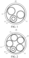
FIG. 1 is a schematic structural diagram of a charging gun cable according to Embodiment I of the present disclosure; -
FIG. 2 is another schematic structural diagram of a charging gun cable according to Embodiment I of the present disclosure; and -
FIG. 3 is a schematic structural diagram of a charging pile according to Embodiment III of the present disclosure. - To make the objectives, technical solutions, and advantages of the present disclosure clearer, the following further describes the present disclosure in detail with reference to the accompanying drawings and the embodiments. It should be understood that specific embodiments described herein are merely used to explain the present disclosure and are not intended to limit the present disclosure.
- Unless otherwise defined, a technical term or a scientific term used in the present disclosure is to have a general meaning understood by a person of ordinary skill in the art of the present disclosure. A similar term such as "include" or "comprise" used in the present disclosure means that an element or object appearing before the term covers an element or object listed after the term and equivalents thereof, but do not exclude other elements or objects. Similar terms such as "connection" or "connected" are not limited to a physical or mechanical connection, but may also include an electrical connection, whether direct or indirect. Terms such as "up", "down", "left", and "right" are only used to indicate a relative positional relationship. When an absolute position of the described object changes, the relative positional relationship may also change accordingly.
- To keep the following description of the embodiments of the present disclosure clear and concise, detailed descriptions of known functions and known components are omitted in the present disclosure.
- To describe the technical solutions of the present disclosure, a description is provided through specific embodiments below.
- Embodiment I of the present disclosure provides a
charging gun cable 10. As shown inFIG. 1 , the charginggun cable 10 includes afirst L wire 11, anN wire 14, aPE wire 12, and aCP wire 13. Thefirst L wire 11, theN wire 14, and thePE wire 12 are arranged adjacent to each other in pairs. ThePE wire 12 is provided with a hollow hole. TheCP wire 13 is located in the hollow hole of thePE wire 12. - The
first L wire 11 refers to a single-phase alternating current (AC) wire. TheN wire 14 refers to an AC neutral wire. ThePE wire 12 refers to an earth wire on the charging gun configured to connect the charging gun and a vehicle to a common ground. TheCP wire 13 refers to a control guide cable for monitoring an interaction function between an electric vehicle and an electric vehicle power supply device. - The
PE wire 12 being provided with a hollow hole means that thePE wire 12 is a hollow wire, the middle of a wire harness is hollow, and theCP wire 13 is located in the hollow hole of thePE wire 12, so that thePE wire 12 forms a shielding layer of theCP wire 13. - The present disclosure provides a charging
gun cable 10. The charginggun cable 10 includes afirst L wire 11, anN wire 14, aPE wire 12, and aCP wire 13. ThePE wire 12 is provided with a hollow hole, and theCP wire 13 is located in the hollow hole of thePE wire 12. According to the present disclosure, theCP wire 13 is arranged in the hollow hole of thePE wire 12, so that thePE wire 12 not only realizes the grounding function, but also shields theCP wire 13. ThePE wire 12 is reused as the shielding wire, to prevent theCP wire 13 from being interfered when transmitting a signal. In addition, thePE wire 12 with the same original wire diameter is used as the shielding wire, so that the function of theoriginal PE wire 12 is not affected. - Regarding a positional relationship between the
PE wire 12 and theCP wire 13, theCP wire 13 is located inside thePE wire 12, and an outer surface of theCP wire 13 may partially contact an inner surface of thePE wire 12, or may completely contact the inner surface of thePE wire 12. As an implementation, thePE wire 12 is a metal layer that wraps theCP wire 13. Preferably, TheCP wire 13 and thePE wire 12 are coaxially arranged, and the technical effect of this implementation is that thePE wire 12 tightly wraps theCP wire 13, thereby improving a shielding effect on theCP wire 13. - For a connection relationship between the
CP wire 13 and another module, theCP wire 13 extends through the hole on thePE wire 12 and connects to the controller in the charging pile. A hole is provided on thePE wire 12 near the controller inside the charging pile for theCP wire 13 to pass through, so as to realize the connection between theCP wire 13 and another module. - Regarding a category of the charging
gun cable 10, as shown inFIG. 1 , when the category of the charginggun cable 10 is a single-phase AC charging cable, the charging gun cable includes only thefirst L wire 11. As shown inFIG. 2 , when the category of the charginggun cable 10 is a three-phase AC charging cable, the charginggun cable 10 further includes asecond L wire 15 and athird L wire 16. Thefirst L wire 11, thesecond L wire 15, thethird L wire 16, theN wire 14, and thePE wire 12 are arranged adjacent to each other in sequence. One arrangement manner is that thefirst L wire 11, thesecond L wire 15, thethird L wire 16, theN wire 14, and thePE wire 12 form a ring. Another arrangement manner is a double-row arrangement, in which thefirst L wire 11, thesecond L wire 15, and thethird L wire 16 are located in a first row, and theN wire 14 and thePE wire 12 are located in a second row. The charginggun cable 10 provided in this embodiment may be used as both a single-phase AC charging cable and a three-phase AC charging cable. - Embodiment II of the present disclosure provides a charging gun, including a charging gun body and a charging gun head. The charging gun head includes the charging gun cable provided in Embodiment I. The charging gun cable extends through the charging gun body and connects to the charging pile.
- Embodiment III of the present disclosure provides a charging pile, including a charging
pile body 30 and the charginggun 20 provided in Embodiment II. - As an implementation, as shown in
FIG. 3 , the charging pile is a single-phase charging pile, and the chargingpile body 30 includes aswitching device 31 and acontroller 32. The switchingdevice 31 connects a first L wire to an N wire. A communication terminal of thecontroller 32 is connected to a CP wire, and a ground terminal of thecontroller 32 is connected to a PE wire. - In this implementation, in the single-phase charging pile, the CP wire is arranged in a hollow hole of the PE wire, so that the PE wire not only realizes the grounding function, but also shields the CP wire. The PE wire is reused as a shielding wire, to prevent the CP wire from being interfered when transmitting a signal.
- As another implementation, the charging pile is a three-phase charging pile. The charging pile body includes a switching device and a controller. The switching device connects the first L wire, a second L wire, a third L wire, and the N wire. A communication terminal of the controller is connected to a CP wire, and a ground terminal of the controller is connected to the PE wire.
- In this implementation, in the three-phase charging pile, the CP wire is arranged in the hollow hole of the PE wire, so that the PE wire not only realizes the grounding function, but also shields the CP wire. The PE wire is reused as the shielding wire, to prevent the CP wire from being interfered when transmitting a signal.
- The foregoing content is a further detailed description of the present disclosure with reference to specific preferred implementations, and it should not be considered that the specific implementation of the present disclosure is limited to these descriptions. All equivalent substitutions or obvious variations made by a person of ordinary skill in the art of the present disclosure without departing from the concept of the present disclosure and having the same performance or use should be deemed to fall within the patent protection scope determined by the submitted claims of the present disclosure.
Claims (10)
- A charging gun cable, comprising:a first L wire (11);an N wire (14);a PE wire (12), the PE wire (12) being provided with a hollow hole; anda CP wire (13), the CP wire (13) being located in the hollow hole of the PE wire (12),wherein the first L wire (11), the N wire (14), and the PE wire (12) are arranged adjacent to each other in pairs.
- The charging gun cable according to claim 1, wherein the PE wire (12) is a shielding layer of the CP wire (13).
- The charging gun cable according to claim 2, wherein the PE wire (12) is a metal layer that wraps the CP wire (13).
- The charging gun cable according to claim 3, wherein the CP wire (13) and the PE wire (12) are coaxially arranged.
- The charging gun cable according to claim 1, wherein the CP wire (13) extends through the hole on the PE wire (12) and connects to a controller in the charging pile.
- The charging gun cable according to claim 1, further comprising:a second L wire (15); anda third L wire (16),wherein the first L wire (11), the second L wire (15), the third L wire (16), the N wire (14), and the PE wire (12) are arranged adjacent to each other in sequence.
- A charging gun, comprising:a charging gun body; anda charging gun head, the charging gun head comprising the charging gun cable according to any of claims 1 to 6.
- A charging pile, comprising a charging pile body (30) and the charging gun (20) according to claim 7.
- The charging pile according to claim 8, wherein the charging pile is a single-phase charging pile, and the charging pile body (30) comprises:a switching device (31), the switching device (31) being configured to connect the first L wire (11) and the N wire (14); anda controller (32), a communication terminal of the controller (32) being connected to the CP wire (13), and a ground terminal of the controller (32) being connected to the PE wire (12).
- The charging pile according to claim 8, wherein the charging pile is a three-phase charging pile, and the charging pile body (30) comprises:a switching device (31), the switching device (31) being configured to connect the first L wire (11), the second L wire (15), the third L wire (16), and the N wire (14); anda controller (32), a communication terminal of the controller (32) being connected to the CP wire (13), and a ground terminal of the controller (32) being connected to the PE wire (12).
Applications Claiming Priority (2)
| Application Number | Priority Date | Filing Date | Title |
|---|---|---|---|
| CN202222297996.XU CN218471664U (en) | 2022-08-30 | 2022-08-30 | Charging cable, charging gun and charging pile |
| PCT/CN2023/108509 WO2024045943A1 (en) | 2022-08-30 | 2023-07-21 | Charging gun cable, charging gun, and charging pile |
Publications (2)
| Publication Number | Publication Date |
|---|---|
| EP4583128A1 true EP4583128A1 (en) | 2025-07-09 |
| EP4583128A4 EP4583128A4 (en) | 2025-12-10 |
Family
ID=85140588
Family Applications (1)
| Application Number | Title | Priority Date | Filing Date |
|---|---|---|---|
| EP23858979.0A Pending EP4583128A4 (en) | 2022-08-30 | 2023-07-21 | CHARGING GUN CABLE, CHARGING GUN AND CHARGING BATTERY |
Country Status (6)
| Country | Link |
|---|---|
| US (1) | US20250187466A1 (en) |
| EP (1) | EP4583128A4 (en) |
| JP (1) | JP2025526960A (en) |
| KR (1) | KR20250034160A (en) |
| CN (1) | CN218471664U (en) |
| WO (1) | WO2024045943A1 (en) |
Families Citing this family (2)
| Publication number | Priority date | Publication date | Assignee | Title |
|---|---|---|---|---|
| CN218471664U (en) * | 2022-08-30 | 2023-02-10 | 比亚迪股份有限公司 | Charging cable, charging gun and charging pile |
| FR3149420B1 (en) * | 2023-05-31 | 2025-04-18 | Psa Automobiles Sa | CHARGING CABLE WITH WIRE SECTION OPTIMIZED FOR CHARGING AN ELECTRIC VEHICLE |
Family Cites Families (9)
| Publication number | Priority date | Publication date | Assignee | Title |
|---|---|---|---|---|
| CN203617029U (en) * | 2013-12-10 | 2014-05-28 | 四川川东电缆有限责任公司 | 5-core electric automobile alternating current charging cable |
| CN203617035U (en) * | 2013-12-10 | 2014-05-28 | 四川川东电缆有限责任公司 | Electric automobile charging cable |
| JP2018152249A (en) * | 2017-03-13 | 2018-09-27 | 株式会社フジクラ | Cable with shield layer |
| CN207449663U (en) * | 2017-11-27 | 2018-06-05 | 北京新能源汽车股份有限公司 | Charging pile |
| CN108454440B (en) * | 2018-03-27 | 2021-04-13 | 浙江吉利控股集团有限公司 | A vehicle-to-vehicle charging device and method |
| CN113246755A (en) * | 2020-02-11 | 2021-08-13 | 武汉路特斯汽车有限公司 | Alternating-current charging control system for low-voltage battery of electric automobile |
| CN216697890U (en) * | 2021-11-01 | 2022-06-07 | 蔚来汽车科技(安徽)有限公司 | Charging cable, charging gun and charging equipment |
| CN216389856U (en) * | 2021-11-22 | 2022-04-26 | 江苏福迪新能源技术有限公司 | A European standard electric vehicle double-ended AC charging gun |
| CN218471664U (en) * | 2022-08-30 | 2023-02-10 | 比亚迪股份有限公司 | Charging cable, charging gun and charging pile |
-
2022
- 2022-08-30 CN CN202222297996.XU patent/CN218471664U/en active Active
-
2023
- 2023-07-21 EP EP23858979.0A patent/EP4583128A4/en active Pending
- 2023-07-21 WO PCT/CN2023/108509 patent/WO2024045943A1/en not_active Ceased
- 2023-07-21 JP JP2025510388A patent/JP2025526960A/en active Pending
- 2023-07-21 KR KR1020257004468A patent/KR20250034160A/en active Pending
-
2025
- 2025-02-25 US US19/062,990 patent/US20250187466A1/en active Pending
Also Published As
| Publication number | Publication date |
|---|---|
| JP2025526960A (en) | 2025-08-15 |
| WO2024045943A1 (en) | 2024-03-07 |
| US20250187466A1 (en) | 2025-06-12 |
| CN218471664U (en) | 2023-02-10 |
| EP4583128A4 (en) | 2025-12-10 |
| KR20250034160A (en) | 2025-03-10 |
Similar Documents
| Publication | Publication Date | Title |
|---|---|---|
| US20250187466A1 (en) | Charging gun cable, charging gun, and charging pile | |
| US4657342A (en) | Flexible power cable with profiled core and support member | |
| KR102420885B1 (en) | An electric power system for supplying electric energy to a vessel | |
| EP2523199B1 (en) | Network apparatus and communication module | |
| EP2960001B1 (en) | Welding system and communication method for welding system | |
| WO2012032932A1 (en) | Power line communication system, power line communication device, and connector device | |
| EP3754803B1 (en) | Joint structure for high-voltage cable | |
| US10513232B2 (en) | Electrical connecting device for transmitting electrical energy and/or data, on-board electrical system and motor vehicle | |
| KR200218788Y1 (en) | High Voltage Ignition Leads Eliminate High Voltage Ignition Noise in Automotive / Motorcycles | |
| EP1160801B1 (en) | High-frequency current multiconductor cable and power feeding equipment for one or more movable bodies using said cable | |
| EP2787516B1 (en) | Transformer and transformer device including same | |
| WO2017013809A1 (en) | Conduction path with noise filter | |
| CN215577784U (en) | Special cable for aramid fiber woven low-temperature rubber vulcanization top drive | |
| US9633762B2 (en) | Cable | |
| CN212724778U (en) | Engine wiring harness and engine | |
| CN110972509A (en) | Power cords, power packs and drones | |
| JP2015047042A (en) | Power supply device | |
| KR20200129366A (en) | Multi output power supplying apparatus | |
| JP2018125800A (en) | Communication system, and welding system | |
| CN114888844A (en) | Mechanical arm | |
| KR20210060592A (en) | Rotating connector device | |
| CN109003717B (en) | Anti-interference control cable | |
| KR20180034465A (en) | Circuits for data communication via supply lines | |
| US11407312B2 (en) | Charging cable for a motor vehicle which can be operated by electricity | |
| CN218983517U (en) | Output circuit of mig-mma-cut multifunctional machine |
Legal Events
| Date | Code | Title | Description |
|---|---|---|---|
| STAA | Information on the status of an ep patent application or granted ep patent |
Free format text: STATUS: THE INTERNATIONAL PUBLICATION HAS BEEN MADE |
|
| PUAI | Public reference made under article 153(3) epc to a published international application that has entered the european phase |
Free format text: ORIGINAL CODE: 0009012 |
|
| STAA | Information on the status of an ep patent application or granted ep patent |
Free format text: STATUS: REQUEST FOR EXAMINATION WAS MADE |
|
| 17P | Request for examination filed |
Effective date: 20250328 |
|
| AK | Designated contracting states |
Kind code of ref document: A1 Designated state(s): AL AT BE BG CH CY CZ DE DK EE ES FI FR GB GR HR HU IE IS IT LI LT LU LV MC ME MK MT NL NO PL PT RO RS SE SI SK SM TR |
|
| DAV | Request for validation of the european patent (deleted) | ||
| DAX | Request for extension of the european patent (deleted) | ||
| A4 | Supplementary search report drawn up and despatched |
Effective date: 20251112 |
|
| RIC1 | Information provided on ipc code assigned before grant |
Ipc: H01B 11/06 20060101AFI20251106BHEP |