EP4583102A2 - Mehrkanal-signalgenerator, audiocodierer und zugehörige verfahren auf der basis eines mischrauschsignals - Google Patents
Mehrkanal-signalgenerator, audiocodierer und zugehörige verfahren auf der basis eines mischrauschsignals Download PDFInfo
- Publication number
- EP4583102A2 EP4583102A2 EP25170947.3A EP25170947A EP4583102A2 EP 4583102 A2 EP4583102 A2 EP 4583102A2 EP 25170947 A EP25170947 A EP 25170947A EP 4583102 A2 EP4583102 A2 EP 4583102A2
- Authority
- EP
- European Patent Office
- Prior art keywords
- channel
- noise
- coherence
- frame
- data
- Prior art date
- Legal status (The legal status is an assumption and is not a legal conclusion. Google has not performed a legal analysis and makes no representation as to the accuracy of the status listed.)
- Pending
Links
Images




Classifications
-
- G—PHYSICS
- G10—MUSICAL INSTRUMENTS; ACOUSTICS
- G10L—SPEECH ANALYSIS TECHNIQUES OR SPEECH SYNTHESIS; SPEECH RECOGNITION; SPEECH OR VOICE PROCESSING TECHNIQUES; SPEECH OR AUDIO CODING OR DECODING
- G10L19/00—Speech or audio signals analysis-synthesis techniques for redundancy reduction, e.g. in vocoders; Coding or decoding of speech or audio signals, using source filter models or psychoacoustic analysis
- G10L19/008—Multichannel audio signal coding or decoding using interchannel correlation to reduce redundancy, e.g. joint-stereo, intensity-coding or matrixing
-
- G—PHYSICS
- G10—MUSICAL INSTRUMENTS; ACOUSTICS
- G10L—SPEECH ANALYSIS TECHNIQUES OR SPEECH SYNTHESIS; SPEECH RECOGNITION; SPEECH OR VOICE PROCESSING TECHNIQUES; SPEECH OR AUDIO CODING OR DECODING
- G10L19/00—Speech or audio signals analysis-synthesis techniques for redundancy reduction, e.g. in vocoders; Coding or decoding of speech or audio signals, using source filter models or psychoacoustic analysis
- G10L19/012—Comfort noise or silence coding
-
- G—PHYSICS
- G10—MUSICAL INSTRUMENTS; ACOUSTICS
- G10L—SPEECH ANALYSIS TECHNIQUES OR SPEECH SYNTHESIS; SPEECH RECOGNITION; SPEECH OR VOICE PROCESSING TECHNIQUES; SPEECH OR AUDIO CODING OR DECODING
- G10L21/00—Speech or voice signal processing techniques to produce another audible or non-audible signal, e.g. visual or tactile, in order to modify its quality or its intelligibility
- G10L21/02—Speech enhancement, e.g. noise reduction or echo cancellation
- G10L21/0208—Noise filtering
- G10L21/0264—Noise filtering characterised by the type of parameter measurement, e.g. correlation techniques, zero crossing techniques or predictive techniques
-
- G—PHYSICS
- G10—MUSICAL INSTRUMENTS; ACOUSTICS
- G10L—SPEECH ANALYSIS TECHNIQUES OR SPEECH SYNTHESIS; SPEECH RECOGNITION; SPEECH OR VOICE PROCESSING TECHNIQUES; SPEECH OR AUDIO CODING OR DECODING
- G10L25/00—Speech or voice analysis techniques not restricted to a single one of groups G10L15/00 - G10L21/00
- G10L25/78—Detection of presence or absence of voice signals
Definitions
- the present invention is related, inter alia, to Comfort Noise Generation (CNG) for enabling Discontinuous Transmission (DTX) in Stereo Codecs.
- CNG Comfort Noise Generation
- the invention also refers to Multi-Channel Signal Generator, Audio Encoder and Related Methods e.g. Relying on a Mixing Noise Signal.
- the invention may be implemented in a device, an apparatus, a system, in a method, in a non-transitory storage unit storing instructions which, when executed by a computer (processor, controller) cause the computer (processor, controller) cause to perform a particular method, and in an encoded multi-channel audio signal.
- Comfort noise generators are usually used in discontinuous transmission (DTX) of audio signals, in particular of audio signals containing speech.
- DTX discontinuous transmission
- the audio signal is first classified in active and inactive frames by a voice activity detector (VAD). Based on the VAD result, only the active speech frames are coded and transmitted at the nominal bit-rate.
- VAD voice activity detector
- SID frames silence insertion descriptor frames
- the noise is generated during the inactive frames at the decoder side by a comfort noise generator (CNG).
- CNG comfort noise generator
- the size of an SID frame is very limited in practice. Therefore, the number of parameters describing the background noise has to be kept as small as possible.
- the noise estimation is not applied directly on the output of the spectral transforms. Instead, it is applied at a lower spectral resolution by averaging the input power spectrum among groups of bands, e.g., following the Bark scale. The averaging can be achieved either by arithmetic or geometric means.
- the limited number of parameters transmitted in the SID frames does not allow to capture the fine spectral structure of the background noise. Hence only the smooth spectral envelope of the noise can be reproduced by the CNG.
- the discrepancy between the smooth spectrum of the reconstructed comfort noise and the spectrum of the actual background noise can become very audible at the transitions between active frames (involving regular coding and decoding of a noisy speech portion of the signal) and CNG frames.
- the 3GPP telecommunications codec for the Enhanced Voice Services (EVS) of LTE [6] is equipped with a Discontinuous Transmission (DTX) mode applying Comfort Noise Generation (CNG) for inactive frames, i.e. frames that are determined to consist of background noise only.
- CNG Comfort Noise Generation
- a low-rate parametric representation of the signal is conveyed by Silence Insertion Descriptor (SID) frames at most every 8 frames (160 ms). This allows the CNG in the decoder to produce an artificial noise signal resembling the actual background noise.
- SID Silence Insertion Descriptor
- CNG can be achieved using either a linear predictive scheme (LP-CNG) or a frequency-domain scheme (FD-CNG), depending on the spectral characteristics of the background noise.
- L-CNG linear predictive scheme
- FD-CNG frequency-domain scheme
- the LP-CNG approach in EVS [7] operates on a split-band basis with the coding consisting of both a low-band and a high-band analysis/synthesis encoding stage.
- the low-band encoding no parameter modeling of the high-band noise spectrum is performed for the high-band signal. Only the energy of high-band signal is encoded and transmitted to the decoder and the high-band noise spectrum is generated purely at the decoder side.
- Both the low-band and the high-band CN is synthesized by filtering an excitation through a synthesis filter. The low-band excitation is derived from the received low-band excitation energy and the low-band excitation frequency envelope.
- the low-band synthesis filter is derived from the received LP parameters in the form of line spectral frequency (LSF) coefficients.
- LSF line spectral frequency
- the high-band excitation is obtained using energy which is extrapolated from the low-band energy and the high-band synthesis filter is derived from a decoder side LSF interpolation.
- the high-band synthesis is spectrally flipped and added to the low-band synthesis to form the final CN signal.
- the FD-CNG approach [8] [9] makes use of a frequency-domain noise estimation algorithm followed by a vector quantization of the background noise's smoothed spectral envelope.
- the decoded envelope is refined in the decoder by running a second frequency-domain noise estimator. Since a purely parametric representation is used during inactive frames, the noise signal is not available at the decoder in this case.
- noise estimation is performed in every frame (active and inactive) at encoder and decoder sides based on the minimum statistics algorithm.
- a method for generating comfort noise in the case of two (or more) channels is described in [10].
- a system for stereo DTX and CNG is described that combines a mono SID with a band-wise coherence measure calculated on the two input stereo channels in the encoder.
- the mono CNG information and the coherence values are decoded from the bitstream and the target coherence in a number of frequency bands is synthesized.
- the coherence values are encoded using a predictive scheme followed by an entropy coding with variable bit rate.
- Comfort noise is generated for each channel with the methods described in the previous paragraphs and then the two CNs are mixed band-wise using a formula with weighting based on transmitted band coherence values included in the SID frame.
- Stereo signals can be coded in a parametrical fashion where a mono downmix of the two stereo channels is applied and this single downmix channel is coded and transmitted to the receiver along with side information that is used to approximate the original stereo signal in the decoder.
- Another approach is to employ discrete stereo coding which aims at removing redundancy between the channels to achieve a more compact two-channel representation of the original signal by means of some signal pre-processing. The two processed channels are then coded and transmitted. At the decoder, an inverse processing is applied. Still, side info relevant for the stereo processing can be transmitted along the two channels. The main difference between parametric and discrete stereo coding methods is therefore in the number of transmitted channels.
- an audio encoder for generating an encoded multi-channel audio signal for a sequence of frames comprising an active frame and an inactive frame, the audio encoder comprising:
- the coherence calculator is configured to quantize the coherence value using a uniform quantizer to obtain the quantized coherence value as an n bit number as the coherence data.
- the noise parameter calculator is configured to calculate: the first gain information by comparing:
- the first audio source is a first noise source and the first audio signal
- the mixer is configured to generate the first channel and the second channel so that an amount of the mixing noise signal in the first channel is equal to an amount of the mixing noise signal in the second channel or is within a range of 80 percent to 120 percent of the amount of the mixing noise signal in the second channel.
- the mixer comprises a control input for receiving a control parameter, and wherein the mixer is configured to control an amount of the mixing noise signal in the first channel and the second channel in response to the control parameter.
- each of the first audio source, the second audio source and the mixing noise source is a Gaussian noise source.
- the first audio source comprises a first noise generator to generate the first audio signal as a first noise signal
- the second audio source comprises a decorrelator for decorrelating the first noise signal to generate the second audio signal as a second noise signal
- the mixing noise source comprises a second noise generator
- one of the first audio source, the second audio source and the mixing noise source comprises a pseudo random number sequence generator configured for generating a pseudo random number sequence in response to a seed, and wherein at least two of the first audio source, the second audio source and the mixing noise source are configured to initialize the pseudo random number sequence generator using different seeds.
- At least one of the first audio source, the second audio source and the mixing noise source is configured to operate using a pre-stored noise table, or
- the mixer comprises:
- the mixer comprises a third amplitude element for influencing an amplitude of the mixing noise signal, wherein an amount of influencing performed by the third amplitude element depends on the amount of influencing performed by the first amplitude element or the second amplitude element, so that the amount of influencing performed by the third amplitude element becomes greater when the amount of influencing performed by the first amplitude element or the amount of influencing performed by the second amplitude element becomes smaller.
- the multi-channel signal generator further comprising:
- the encoded audio data for the inactive frame comprises silence insertion descriptor data comprising comfort noise data indicating a signal energy for each channel of the two channels for the inactive frame and indicating a coherence between the first channel and the second channel in the inactive frame, and
- the audio data for the inactive frame comprises:
- a spectrum-time converter for converting a resulting first channel and a resulting second channel being spectrally adjusted and coherence-adjusted, into corresponding time domain representations to be combined with or concatenated to time domain representations of corresponding channels of the decoded multi-channel signal for the active frame.
- the audio data for the inactive frame comprises:
- the first audio source is a first noise source and the first audio signal is a first noise signal
- the second audio source is a second noise source and the second audio signal is a second noise signal
- the method of generating a multi-channel signal having a first channel and a second channel comprising:
- an audio encoder for generating an encoded multi-channel audio signal for a sequence of frames comprising an active frame and an inactive frame, the audio encoder comprising:
- the coherence calculator is configured to calculate a coherence value and to quantize the coherence value to obtain a quantized coherence value, wherein the output interface is configured to use the quantized coherence value as the coherence data in the encoded multi-channel signal.
- the coherence calculator is configured:
- the coherence calculator is configured to calculate the real intermediate value as a sum over real parts of products of complex spectral values for corresponding frequency bins of the first channel and the second channel in the inactive frame, or to calculate the imaginary intermediate value as a sum over imaginary parts of products of the complex spectral values for corresponding frequency bins of the first channel and the second channel in the inactive frame.
- the coherence calculator is configured to square a smoothed real intermediate value and to square a smoothed imaginary intermediate value and to add the squared values to obtain a first component number, wherein the coherence calculator is configured to multiply the smoothed first and second energy values to obtain a second component number, and to combine the first and the second component numbers to obtain a result number for the coherence value, on which the coherence data is based.
- an audio encoder wherein the coherence calculator is configured to calculate a square root of the result number to obtain a coherence value on which the coherence data is based.
- the coherence calculator is configured to quantize the coherence value using a uniform quantizer to obtain the quantized coherence value as an N bit number as the coherence data.
- an audio encoder configured to:
- the uniform quantizer is configured to calculate an N bit number so that the value for N is equal to a value of bits occupied by the comfort noise generation side information for the first silence insertion descriptor frame.
- the method of audio encoding for generating an encoded multi-channel audio signal for a sequence of frames comprising an active frame and an inactive frame comprising:
- the encoded multi-channel audio signal organized in a sequence of frames, the sequence of frames comprising an active frame and an inactive frame, the encoded multi-channel audio signal comprising: encoded audio data for the active frame;
- At least one of the blocks below may be controlled by a controller.
- the encoder it is not necessary for the encoder to provide the complete audio signal for the inactive frame, but only the coherence value and the parametric representation of the noise shape, thereby reducing the amount of bits to be encoded in the bitstream.
- Figs. 3a-3f show examples of a CNG, or more in general a multi-channel signal generator 200, for generating a multi-channel signal 204 having a first channel 201 and a second channel 203.
- generated audio signals 221 and 223 are considered to be noise but different kinds of signals are also possible which are not noise.
- Fig. 3f which is general, while Figs. 3a-3e show particular examples.
- a first audio source 211 may be a first noise source and may be indicated here to generate the first audio signal 221, which may be a first noise signal.
- the mixing noise source 212 may generate a mixing noise signal 222.
- the second audio source 213 may generate a second audio signal 223 which may be a second noise signal.
- the multi-channel signal generator 200 may mix the first audio signal (first noise signal) 221 with the mixing noise signal 222 and the second audio signal (second noise signal) 223 with the mixing noise signal 222.
- the first audio signal 221 may be mixed with a version 221a of the mixing noise signal 222
- the second audio signal 223 may be mixed with a version 221b of the mixing noise signal 222, wherein the versions 221a and 221b may differ, for example, for a 20% from each other; each of the versions 221a and 221b may be, for example, an upscaled and/or downscaled version of a common signal 222).
- a first channel 201 of the multi-channel signal 204 may be obtained from the first audio signal (first noise signal) 221 and the mixing noise signal 222.
- the second channel 203 of the multi-channel signal 204 may be obtained from the second audio signal 223 mixed with the mixing noise signal 222.
- the signals may be here in the frequency domain, and k refers to the particular index or coefficient (associated with a particular frequency bin).
- the first audio signal 221, the mixing noise signal 222 and the second audio signal 223 may be decorrelated with each other. This may be obtained, for example, by decorrelating the same signal (e.g. at a decorrelator) and/or by independently generating noise (examples are provided below).
- a mixer 208 may be implemented for mixing the first audio signal 221 and the second audio signal 223 with the mixing noise signal 222.
- the mixing may be of the type of adding signals (e.g. at adder stages 206-1 and 206-3) after that the first audio signal 221, the mixing noise signal 222 and the second audio signal 223 have been weighted by scaling (e.g., at amplitude elements 208-1, 208-2, 208-3).
- Mixing is of the type "adding together after weighting”.
- Figs. 3a-3f show the actual signal processing that is applied to generate the noise signals N l [k] and N r [k] with the addition (+) element denoting the sample-wise addition of two signals (k is the index of the frequency bin).
- the amplitude elements (or weighting elements or scaling elements) 208-1, 208-2 and 208-3 may be obtained, for example, by scaling the first audio signal 221, the mixing noise signal 222, and the second audio signal 223 by suitable coefficients, and may output a weighted version 221' of the first audio signal 221, a weighted version 222' of the mixing noise signal 222, and a weighted version 223' of the second audio signal 223.
- the suitable coefficients may be sqrt(coh) and sqrt(1-coh) and may be obtained, for example, from coherence information encoded in signaling a particular descriptor frame (see also below) (sqrt refers here to the square root operation).
- the coherence "coh” is below discussed in detail, and may be, for example, that indicated with “c” or “c ind “ or “c q " below, e.g. encoded in a coherence information 404 of a bitstream 232 (see below, in combination with Figs. 2 and 4 ).
- the mixing noise signal 222 may be subjected, for example, to a scaling by a weight which is a square root of a coherence value, while the first audio signal 221 and the second audio signal 222 may be scaled by a weight which is the square root of the value complementary to one of the coherence coh.
- the mixing noise signal 222 may be considered as a common mode signal, a portion of which is mixed to the weighted version 221' of the first audio signal 221 and the weighted version 223' of the second audio signal 223 so as to obtain the first channel 201 of the multi-channel signal 204 and the second channel 203 of the multi-channel signal 204, respectively.
- the first noise source 211 or the second noise source 213 may be configured to generate the first noise signal 221 or the second noise signal 223 so that the first noise signal 221 and/or the second noise signal 223 is decorrelated from the mixing noise signal 222 (see below with reference to Figs. 3b-3e ).
- At least one (or each of) the first audio source 211, the second audio source 213 and the mixing noise source 212) may be a Gaussian noise source.
- At least one of the first audio source 211 (211a), the second audio source 213 (213a) and the mixing noise source 212 (212a) may operate using a pre-stored noise table, which may therefore provide a random sequence.
- Each audio source 211, 212, 213 may include at least one audio source generator (noise generator) which generates the noise, for example, in terms of N 1 [k], N 2 [k], Ns[k].
- audio source generator noise generator
- the multi-channel signal generator 200 of Figs. 3a-3f may be used, for example, for a decoder 200a, 200b (200').
- the multi-channel signal generator 200 can be seen as a part of the comfort noise generator (CNG) 220 in Fig. 4 .
- the decoder 200 may be used in general for decoding signals which have been encoded by an encoder, or by generating signals which to be shaped by energy information obtained from a bitstream, so as to generate an audio signal which corresponds to an original input audio signal input to the encoder.
- the silence insertion descriptor frames (the so-called “inactive frames 308", which may be encoded as SID frames 241 and/or 243, for example) are provided in general below bit rate information and are therefore less frequently provided than the normal speech frames (the so-called “active frames 306", see also below). Further, the information which is present in the silence insertion description frames (SID, inactive frames 308) is in general limited (and may substantially correspond to energy information on the signal).
- the audio sources 211, 212, 213 may process signals (e.g., noise) which may be independent and uncorrelated with each other.
- the first audio signal 221, the mixing noise signal 222 and the second audio signal 223 may notwithstanding be scaled by coherence information provided by the encoder and inserted in the bitstream. As can be seen from Figs.
- the coherence value may be the same of the mixing noise signal 222 provides a common mode signal to both the first audio signal 221 and the second audio signal 223, hence permitting to obtain the first channel 201 and the second channel 203 of the multi-channel signal 204.
- the coherence signal is in general a value between 0 and 1:
- the first audio source (211) may be a first noise source and the first audio signal (221) may be a first noise signal, or the second audio source (213) is a second noise source and the second audio signal (223) is a second noise signal.
- the first noise source (211) or the second noise source (213) may be configured to generate the first noise signal (221) or the second noise signal (223), so that the first noise signal (221) or the second noise signal (223) is decorrelated from the mixing noise signal (222).
- the mixer (206) may be configured to generate the first channel (201) and the second channel (203) so that the amount of the mixing noise signal (222) in the first channel (201) is equal to the amount of the mixing noise signal (222) in the second channel (203), or is within a range of 80 percent to 120 percent of the amount of the mixing noise signal (222) in the second channel (203) (e.g. its portions 221a and 221b are different within a range of 80 percent to 120 percent from each other and from the original mixing noise signal 222).
- the mixer (206) and/or the CNG 220 may comprise a control input for receiving a control parameter (404, c).
- the mixer (206) may therefore be configured to control the amount of the mixing noise signal (222) in the first channel (201) and the second channel (203) in response to the control parameter (404, c).
- Figs. 3a-3f it is shown that the mixing noise signal 222 is subjected to a coefficient sqrt(coh), and the first and second audio signals 221, 223 are subjected to a coefficient sqrt(1-coh).
- Fig. 3a shows a CNG 220a in which the first source 211a (211), the second source 213a (213) and the mixing noise source 212a (212) comprise different generators. This is not strictly necessary, and several variants are possible.
- the decoder 200' may include, besides the CNG 220 of Fig. 3 , also an input interface 210 for receiving encoded audio data in a sequence of frames comprising an active frame and an inactive frame following the active frame; and an audio decoder for decoding coded audio data for the active frame to generate a decoded multi-channel signal for the active frame, wherein the first audio source 211, the second audio source 213, the mixing noise source 212 and the mixer 206 are active in the inactive frame to generate the multi-channel signal for the inactive frame.
- the active frames are those which are classified by the encoder as having speech (or any other kind of non-noise sound) and the inactive frames are those which are classified to have silence or only noise.
- Any of the examples of the CNG 220 (220a-220e) may be controlled by a suitable controller.
- the encoder may encode active frames and inactive frames.
- the encoder may encode parametric noise data (e.g. noise shape and/or coherence value) without encoding the audio signal entirely.
- the encoding of the inactive audio frames may be reduced with respect to the active audio frames, so as to reduce the amount of information to be encoded in the bitstream.
- the parametric noise data e.g. noise shape
- the parametric noise data may be given in the left/right domain or in another domain (e.g. mid/side domain), e.g.
- first linear combination between parametric noise data of the first and second channels and a second linear combination between parametric noise data of the first and second channels (in some cases, it is also possible to provide gain information which are not associated to the first and second linear combinations, but are given in the left/right domain).
- the first and second linear combinations are in general linearly independent from each other.
- the encoder may include an activity detector which classifies whether a frame is active or inactive.
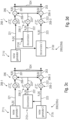
- Figs. 1 , 2 and 4 show examples of encoders 300a and 300b (which are also referred to as 300 when it is not necessary to distinguish between the encoder 300a from the encoder 300b).
- Each audio encoder 300 may generate an encoded multi-channel audio signal 232 for a sequence of frames of an input signal 304.
- the input signal 304 is here considered to be divided between a first channel 301 (also indicated as left channel or "I", where "I” is the letter whose capital version is "L” and is the first letter of "left” in English) and a second channel 303 (or “r", where "r” is the letter whose capital version is "R” and is the first letter of "right” in English).
- the encoded multi-channel audio signal 232 may be defined in a sequence of frames, which may be, for example, in the time domain (e.g. each sample "n" may refer to a particular time instant and the samples of one frame may form a sequence, e.g., a sampling sequence of an input audio signal or a sequence after having filtered an input audio signal).
- Encoder 300 may include an activity detector 380, which is not shown in Figs. 2 and 4 (despite being in some examples implemented therein), but is shown in Fig. 1.
- Fig. 1 shows that each frame of the input signal 304 may be classified either an "active frame 306" or an "inactive frame 308".
- An inactive frame 308 is so that the signal is considered to be silence (and, for example, there is only silence or noise), while the active frame 306 may have some detection of no-noise audio signal (e.g., speech, music, etc.).
- the information on whether the frame is an active frame 306 or a silence frame 308 may be signalled for example in the so-called “comfort noise generation side information” 402 (p_frame), also called “side information”.
- Fig. 1 shows a pre-processing stage 360 which may determine (e.g. classify) whether a frame is an active frame 306 or silent frame 308.
- the channels 301 and 303 of the input signal 304 are indicated with capital letters, like L (301, left channel) and R (303, right channel) to indicate that they are in the frequency domain.
- a spectral analysis step stage 370 may be applied (a first spectral analysis 370-1 to the first channel 301, L; and a second stage 370-3 for the second channel 303, R).
- the spectral analysis stage 370 may be performed for each frame of the input signal 304 and may be based, for example, on harmonicity measurements.
- the spectral analysis is performed by stage 370 on the first channel 301 may be performed separately from the spectral analysis performed on second channel 303 of the same frame.
- the spectral analysis stage 370 may include the calculation of energy-related parameters, such as the average energy for a range of predefined frequency bands and the total average energy.
- An activity detection stage 380 (which may be considered a voice activity detection in the case of the voice is searched for) can be applied.
- a first activity detection stage 380-1 may be applied to the first channel 301 (and in particular to the measurements performed on the first channel), and the second activity detection stage 380-3 may be applied to the second channel 303 (and in particular to the measurements performed on the second channel).
- the activity detection stage 380 may estimate the energy of the background noise in the input signal 304 and use that estimate to calculate a signal-to-noise ratio, which is compared to a signal-to-noise-ratio threshold to determine whether the frame is classified to be active or inactive (i.e.
- the stage 380 may compare the harmonicity as obtained by the spectral analysis stages 370-1 and 370-3, respectively, with one or two harmonicity thresholds (e.g., a first threshold for the first channel 301 and a second threshold for the second channel 303). In both cases, it may be possible to classify not only each frame, but also each channel of each frame as being either an active channel or an inactive channel.
- a decision 381 may be performed, and on the basis of it, it is possible to decide (as identified by switch 381') whether to perform a discrete stereo processing 306a or a stereo discontinuous transmission processing (stereo DTX) 306b.
- a discrete stereo processing 306a or a stereo discontinuous transmission processing (stereo DTX) 306b.
- the encoding can be performed according to any strategy or processing standard or process, and is therefore here not further analyzed in detail. Most of the discussion below will regard to the stereo DTX 306b.
- a frame is classified (at stage 381) as inactive frame only if both channels 301 and 303 are classified as inactive by stages 380-1 and 380-3, respectively. Therefore, problems are avoided in the activity detection decision as discussed above. In particular, it is not necessary to signal the classification of active/inactive for each channel for each frame (thereby reducing the signalling), and a synchronization between the channels is inherently obtained. Further, where the decoder is as discussed in the present document, it is possible to make use of the coherence between the first and second channels 301 and 303 and to generate some noise signals, which are correlated/decorrelated according to the coherence obtained for the signal 304. Now, the elements of the encoder 300 (300a, 300b) which are used for encoding the inactive frame are discussed in detail. As explained, any other technique may be used for encoding the active frames 308, and is therefore not discussed here.
- the encoder 300a, 300b (300) may include a noise parameter calculator 3040 for calculating parametric noise data 401, 403 for the first and second channels 301, 303.
- the noise parameter calculator 3040 may calculate parametric noise data 401, 403 (e.g. indices and/or gains) for the first channel 301 and the second channel 303.
- the noise parameter calculator 3040 may therefore provide encoded audio data 232 in a sequence of frames which may comprise active frames 306 and inactive frames 308 (which may follow the active frames 306).
- the encoded audio data 232 may be encoded as one or two silence insertion description frames (SID) 241, 243. In some examples (e.g. in Fig. 2 ), there is only one single SID frame, in some other, there are two SID frames (e.g. in Fig. 4 ).
- An inactive frame 308 may include, in particular, at least one of:
- a first silence insertion descriptor frame 241 may include the first two items of the list above, and a second silence insertion descriptor frame 243 may include the last two features in the specific data fields.
- different protocols may provide different data fields or different organization of the bitstream.
- the coherence information may include one single value (e.g., encoded in few bits, like four bits) which indicates coherence information (e.g., correlation data), e.g. the coherence between the first channel 301 and the second channel 303 of the same inactive frame 308.
- the comfort noise parameter data 401, 403 may indicate, for each channel 301, 303, signal energy for the inactive frame 308 (e.g., it may substantially provide an envelope), or anyway may provide noise shape information.
- the envelope or the noise shape information may be in the form of multiple coefficients for frequency bins and a gain for each channel.
- the noise shape information may be obtained at stage 312 (see below) using the original input channels (301, 303) and then the mid/side encoding is done on the noise shape parameter vectors. It will be shown that in the decoder it may be possible to generate some noise channels (e.g. 201, 203 as in Fig. 3 ) which may be influenced by the coherence information 404.
- the noise channels 201, 203 generated by the CNG 220 (220a-220) may therefore be modified by a signal modifier 250 controlled by the control noise data (comfort noise parameter data 401, 403, 2312) which indicate signal energies for the first audio channel L out and the second audio channel R out .
- the audio encoder 300 may include a coherence calculator 320, which may obtain the coherence information (404) to be encoded in the bitstream (e.g. signal 232, frame 241 or 243).
- the coherence information (c, 404) may indicate a coherence situation between the first channel 301 (e.g. left channel) and the second channel 303 (e.g. right channel) in the inactive frame 308. Examples thereof will be discussed later.
- the encoder 300 may include an output interface 310 configured for generating the multi-channel audio signal 232 (bitstream) with the encoded audio data for the active frame 306 and, for the inactive frame 308, the first parametric data (comfort noise parametric data) 401 (p_noise, left) the second parametric noise data (p_noise,right 403) and the coherence data c (404).
- the first parametric data 401 may be parametric data of the first channel (e.g. left channel) or a first linear combination of the first and second channel (e.g. mid channel).
- the second parametric data 403 may be parametric data of the second channel (e.g. right channel) or a second linear combination of the first and second channel (e.g. side channel) different from the first linear combination.
- bitstream 232 there may also be side information 402, including an indication for whether the current frame is an active frame 306 or an inactive frame 308, e.g. to inform the decoder of the decoding techniques to be used.
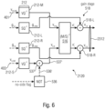
- Fig. 4 shows the noise parameter calculator (compute noise parameter stage) 3040 as including a first noise parameter calculator stage 304-1 in which the comfort noise parameter data 401 for the first channel 301 may be computed, and a second noise parameter calculator stage 304-3, in which the second comfort noise parameter 403 for the second channel 303 may be computed.
- Figure 2 shows an example where the noise parameters are processed and quantized jointly. Internal parts (e.g. conversion of the noise shape vectors into M/S representation) are shown in figure 5 .
- a coherence calculator 320 may calculate the coherence data (coherence information) c (404) which indicates the coherence situation between the first channel L and the second channel R. In this case, the coherence calculator 320 may operate in the frequency domain.
- the coherence calculator 320 may include a compute channel coherence stage 320' in which coherence value c (404) is obtained. Downstream thereto, a uniform quantizer stage 320" may be used. Hence, it may be obtained a quantized version c ind of the coherence value c.
- the coherence calculator 320 may, in some examples:
- the coherence calculator 320 may square a smoothed real intermediate value and to square a smoothed imaginary intermediate value and to add the squared values to obtain a first component number.
- the coherence calculator 320 may multiply the smoothed first and second energy values to obtain a second component number, and combine the first and the second component numbers to obtain a result number for the coherence value, on which the coherence data is based.
- the coherence calculator 320 may calculate a square root of the result number to obtain a coherence value on which the coherence data is based. Examples of formulas are provided below.
- noise shape or other signal energy
- What will be encoded is basically the shape (or other information relating to the energy) of the noise of the original input signal 302, which at the decoder will be applied to generated noise 203 and will shape it, so as to render a noise 252 (output audio signal) which resembles the original noise of the signal 304.
- noise information e.g., energy information, envelope information
- the signal 304 may be encoded in the bitstream 232, so as to subsequently generate a noise signal which has the noise shape encoded by the encoder.
- a get noise shape block 312 may be applied to the input signal 304 of the encoder.
- the "get noise shape” block 312 may calculate a low-resolution parametrical representation 1312 of the spectral envelope of the noise in the input signal 304. This can be done, for example, by calculating energy values in frequency bands of the frequency domain representation of the input signal 304. The energy values may be converted into a logarithmic representation (if necessary) and may be condensed into a lower number (N) of parameters that are later used in the decoder to generate the comfort noise.
- These low-resolution representations of the noise are here referred to as "noise shapes" 1312.
- gains g l and g r may be calculated. Notably, the gains are valid for all the samples of the noise shape of the same channel (v' l and v' r ) of the same inactive frame 306.
- the gains g l and g r may be obtained by taking into consideration the totality (or almost the totality) of the frequency bins in the noise shape representations v' l and v' r .
- the gain g l may be obtained by comparing:
- the gain g r may be obtained by comparing:
- the gain may be, in the linear domain, for example, proportional to a geometrical average of a multiplicity of fractions, each fraction being a fraction between the coefficients of noise shape of a particular channel in the L/R domain (upstream to the L/R-to-M/S converter 314) and the coefficients of the same channel once reconverted in the L/R domain downstream to the M/S-to-L/R converter 324.
- the gain may be obtained as being proportional to an algebraic average between the differences between the coefficients the coefficients of the FD version of the noise shape in the L/R domain (upstream to the L/R-to-M/S converter 314) and the coefficients of the noise shape once reconverted in the L/R domain downstream to the M/S-to-L/R converter 324.
- the gain may provide a relationship between a version of the noise shape of the left or right channel before L/R-to-M/S conversion and quantization with a version of the noise shape of the left or right channel after dequantization and M/S-to-L/R reconversion.
- a quantization stage 328 may be applied to the gain g l to obtain a quantized version thereof indicated with g l,q , to the gain g r to obtain a quantized version thereof indicated with g r,q which may be obtained from the non-quantized gain g r .
- the gains g l,q and g r,q may be encoded in the bitstream 232 (e.g. as comfort noise parameter data 401 and/or 403) to be read by the decoder.
- ⁇ which may be a positive real value
- ⁇ which in this case is 0.1, but could also be a different value, such as a value between 0.05 and 0.15.
- the flag may be 1 or 0 according the particular application in case the energy is exactly equal to the energy threshold.
- Block 436 negates the binary value of the no-side flag 436 (if the input of block 436 is 1, then the output 436' is 0; if the input of block 436 is 0, then the output 436' is 1).
- Block 436 is shown as providing as output 436' the opposite value of the flag.
- the value 436' may be 1, and if the energy of the side representation v s of the noise shape is less than the predetermined threshold, then the value 436' is 0. It is noted that the dequantized value v s,q may be multiplied by the binary value 436'. This is simply one possible way for obtaining that, if the energy of the side representation v s of the noise shape is less than the predetermined energy threshold ⁇ , then the bins of the dequantized side representation v s,q of the noise shape are artificially zeroed (the output 437' of the block 437 would be 0).
- the output 437' of the block 437 may be exactly the same as v s,q . Accordingly, if the energy of the side representation v s of the noise shape is less than the predetermined energy threshold ⁇ , the side representation v s of the noise shape (and in particular its dequantized version v s,q ) is not taken into consideration obtaining the left/right representations of the noise shape. (It will be shown that in addition or alternative also the decoder may have a similar mechanism which zeroes the coefficients of the side representation of the noise shape). It is noted that the no-side flag may also be encoded in the bitstream 232 as part of the side information 402.
- the energy of the side representation of the noise shape is shown as being measured (by block 435) before normalization of the noise shape (at block 316), and the energy is not normalized before comparing it to the threshold. It may, in principle, also be measured by block 435 after normalizing the noise shape (e.g., the block 435 could be input by the v s,n instead of v s ).
- the value 0.1 can be, in some examples, arbitrarily chosen.
- the threshold ⁇ may be chosen after experimentation and tuning (e.g. through calibration).
- the threshold ⁇ may be an implementation-specific parameter which may be input after a calibration.
- output interface (310) may be configured:
- a reduced resolution may be used for the inactive frames, hence further reducing the amount of bits used for encoding the bitstream.
- Any of the examples of the encoder may be controlled by a suitable controller.
- a decoder may include, for example, a comfort noise generator 220 (220a-220e) discussed above, e.g. shown in Figs. 3a-3f .
- the comfort noise 204 multi-channel audio signal
- the comfort noise 204 may be shaped at a signal modifier 250, to obtain the output signal 252.
- Fig. 4 shows a first example of decoder 200', here indicated with 200' (200b).
- the decoder 200' includes a comfort noise generator 220 which may include a generator 220 (220a-220e) according to any of Figs. 3a-3f .
- a signal modifier 250 (not shown, but shown in Fig. 4 ) may be present, to shape the generated multi-channel noise 204 according to energy parameters encoded in comfort noise parameter data (401, 403).
- the decoder 200' may obtain from the bitstream 232 the comfort noise parameter data (401, 403), which may include comfort noise parameter data describing the energy of the signal (e.g., for a first channel and a second channel, or for a first linear combination and second linear combination of the first and second channels, the first and second linear combinations being linearly independent from each other).
- the decoder 200' may obtain coherence data 404, which indicate the coherence between different channels. Fig.
- the output of the decoder 200b is a multi-channel output
- a decoder 200' (here called indicated with 200a) which is an example of the decoder 200, which can be used for generating the output signal 252, e.g. in form of noise.
- the decoder 200a (200') may include an input interface 210 for receiving the encoded audio data 232 (bitstream) in the sequence of frames 306, 308, as encoded by the encoder 300a or 300b, for example.
- the decoder 200a (200') may be, or more in general be part of, a multi-channel signal generator 200 which may be or include the comfort noise generator 220 (220a-220e) of any of Figs. 3a-3f , for example.
- Fig. 2 shows a stereo, comfort noise generator (CNG) 220 (220a-220e).
- the comfort noise generator 220 (220a-220e) may be like that of Figs. 3a-3f or one of its variants.
- a coherence information 404 e.g., c, or more precisely c q also indicated with "coh” or c ind ), as obtained from the encoder 300a or 300b may be used for generating the multi-channel signal 204 (in the channels 201, 203) which have been discussed before.
- the multi-channel signal 204 as generated by the CNG 220 (220a-220e) may be actually further modified, e.g.
- the comfort noise parameter data 401 and 403 e.g. noise shape information for a first (left) channel and a second (right) channel of the multi-channel signal to be shaped.
- the side information 402 may permit to determine whether the current frame is an active frame 306 or an inactive frame 308.
- the elements of Fig. 2 refer to the processing of the inactive frames 308, and it is intended that any technique may be used for the generation of the output signal in the active frames 306, which are therefore not an object of the present document.
- comfort noise data may include, as explained above, coherence information (data) 404, parameters 401 and 403 (v m, ind and v s, ind ) indicating noise shape, and/or gains (g l,q and g r,q ).
- Stage 212-C may dequantize the quantized version c ind of the coherence information 404, to obtain the dequantized coherence information c q .
- Stage 2120 may permit to dequantize the other comfort noise data obtained from the bitstream 232.
- a dequantization stage 212 is formed by other dequantization stages here indicated with 212-M, 212-S, 212-R, 212-L.
- Stage 212-M may dequantize the mid channel noise shape parameters 401 and 403, to obtain the dequantized noise shape parameters v m,q and v s,q .
- the stage 212-S may provide the dequantized version v s, q of the side channel noise shape parameters 403 (v s, ind ).
- the no-side flag so as to zero the output of stage 212-S in case the energy of the noise shape vector v s is recognized, by block 435 at the encoder 300a, as being less than the predetermined threshold ⁇ .
- the dequantized version v s,q of the noise shape vector v s may be zeroed (which conceptually is shown as a multiplication by a flag 536' obtained from a block 536 which has the same function of encoder's block 436, even though block 536 actually reads a no-side flag encoded in the side information of the bitstream 232, without performing any comparison with the threshold ⁇ ).
- the dequantized version v s,q of the noise shape vector v s is artificially zeroed and the value at the output 537' of the scaler block 537 is zero. Otherwise, if the energy is greater than the predetermined threshold, then the output 537' is the same of the quantized version v s, q of the side indices 403 (v s, ind ) of the noise shape of the side channel. In other terms, the values of the noise shape vector v s, ind are neglected in case of energy of the side channel being below the predetermined energy threshold ⁇ .
- an M/S-to-L/R conversion is performed, so as to obtain an L/R version v' l , v' r of the parametric data (noise shape).
- a gain stage 518 (formed by stages 518-L and 518-L) may be used, so that at stage 518-L the channel v' l is scaled by the gain g l,d , while at stage 518-R, the channel v' r is scaled by the gain g r,q . Therefore, the energy channels v l, q and v r, q may be obtained as output of the gain stage 518.
- the stages block 518-L and 518-R are shown with the "+” because the transmission of the values is imagined to be in the logarithmic domain, and the scaling of values is therefore indicated in addition.
- the gain stage 518 indicates that the reconstructed noise shape vectors v l, q and v r, q are scaled.
- the reconstructed noise shape vectors v l, q and v r, q are here complexively indicated with 2312 and are the reconstructed version of the noise shape 1312 as originally obtained by the "get noise shape" block 312 at the encoder.
- each gain is constant for all the indices (coefficients) of the same channel of the same inactive frame.
- the indices v m, ind , v s, ind and gains g l,q , g r,q are coefficients of noise shape and give information on the energy of the frame. They basically refer to parametric data associated to the input signal 304 which are used to generate the signal 252, but they do not represent the signal 304 or the signal 252 to be generated. Said another way, the noise channels v r, q and v l, q describe an envelope to be applied to the multi-channel signal 204 generated by the CNG 220.
- the reconstructed noise shape vectors v l, q and v r, q (2312) are used at the signal modifier 250, to obtain a modified signal 252 by shaping the noise 204.
- the first channel 201 of the generated noise 204 may be shaped by the channel v l, q at stage 250-L, and the channel 203 of the generated noise 204 at at stage 250-R to obtain the output multi-channel audio signal 252 (L out and R out ).
- the comfort noise signal 204 itself is not generated in the logarithmic domain: only the noise shapes may use a logarithmic representation. A conversion from the logarithmic domain to the linear domain may be performed (although not shown).
- the decoder 200' may also comprise a spectrum-time converter (e.g. the signal modifier 250) for converting the resulting first channel 201 and the resulting second channel 203 being spectrally adjusted and coherence-adjusted, into corresponding time domain representations to be combined with or concatenated to time domain representations of corresponding channels of the decoded multi-channel signal for the active frame.
- a spectrum-time converter e.g. the signal modifier 250
- This conversion of the generated comfort noise into a time-domain signal happens after the signal modifier block 250 in Fig. 2 .
- the "combination with or concatenation to" part basically means that before or after an inactive frame which employs one of these CNG techniques, there can also be active frames (other processing path in Fig. 1 ) and to generate a continuous output without any gaps or audible clicks etc., the frames need to be correctly concatenated.
- the first number of frequency bins may be greater than the second number of frequency bins.
- any of the examples of the decoder may be controlled by a suitable controller.
- the noise parameters coded in the two SID frames for the two channels are computed as in EVS [6] such as LP-CNG or FD-CNG or both. Shaping of the Noise energy in the decoder is also the same as in EVS, such as LP-CNG or FD-CNG or both.
- the coherence of the two channels is computed, uniformly quantized using four bits and sent in the bitstream 232.
- the CNG operation may then be controlled by the transmitted coherence value 404.
- Three Gaussian noise sources N 1 , N 2 , N 3 (211a, 212a, 213a; 211b, 212b, 213b; 211c, 212c, 213c; 211d, 212d, 213d; 211e, 212e, 213e) may be used as shown Figs. 3a-3f .
- mainly correlated noise may be added to both channels 221' and 223', while more uncorrelated noise is added if the coherence 404 is low.
- parameters for comfort noise generation may be constantly estimated in the encoder (e.g. 300, 300a, 300b). This may be done, for example, by applying the Frequency-domain noise estimation algorithm (e.g. [8]) e.g. as described in [6] separately on both input channels (e.g. 301, 303) to compute two sets of Noise Parameters (e.g. 401, 403), which are also explained as parametric noise data. Additionally, the coherence (c, 404) of the two channels may be computed (e.g.
- M 256
- ⁇ denotes the real part of a complex number
- ⁇ denotes the imaginary part of a complex number
- ⁇ * denotes complex conjugation.
- This passage may be part of the "Compute Channel Coherence" block 320' at the encoder. This is a temporal smoothing of internal parameters, to avoid large sudden jumps in the parameters between frames. In other terms, a lowpass filter is applied here to the parameters.
- Encoding of the estimated noise parameters 1312, 2312 for both channels may be done separately, e.g. as specified in [6].
- Two SID frames 241, 243 may then be encoded and sent to the decoder.
- the first SID frame 241 may contain the estimated noise parameters 401 of channel L and (e.g. four) bits of side information 402, e.g. as described in [6].
- the noise parameters 403 of channel R may be sent along with the four-bit-quantized coherence value c, 404 (different amounts of bits may be chosen in different examples).
- both SID frame's noise parameters (401, 403) and the first frame's side information 402 may be decoded, e.g. as described in [6].
- noise sources 211, 212, 213 may be used as shown in figure 3 .
- the noise sources 211, 212, 213 may be adaptively summed together (e.g. at adder stages 206-1 and 206-3) e.g. based on the coherence value (c, 404).
- N l k 1 ⁇ c ⁇ ⁇ N 1 k + j ⁇ N 1 k + M + c ⁇ ⁇ N 2 k + j ⁇ N 2 k + M
- N l and N r are complex-valued vectors of length M
- N1, N2 and N3 are real-valued vectors of length 2 ⁇ M.
- the noise signal 204 in the two channels are spectrally shaped (e.g. within stages 250-L, 250-R in Fig. 2 ) using their corresponding noise parameters (2312) decoded from the respective SID frame and subsequently transformed back to the time domain (e.g. as described in [6]) for the frequency-domain comfort noise generation.
- Any of the examples of the processing may be performed by a suitable controller.
- FIG. 1 A block diagram of the generic framework of the encoder is depicted in Fig. 1 .
- the current signal may be classified as either active or inactive by running a VAD on each channel separately as described in [6].
- the VAD decision may then be synchronized between the two channels.
- a frame is classified as an inactive frame 308 only if both channels are classified as inactive. Otherwise, it is classified as active and both channels are jointly coded in an MDCT-based system using band-wise M/S as described in [10].
- the signals may enter the SID encoding path as shown in Fig. 3 .
- Noise Parameters for comfort noise generation (e.g. Noise Parameters) may be constantly estimated in the encoder (e.g. 300, 300a, 300b) for both active and inactive frames (306, 308). This may be done, e.g., by applying a Frequency-domain noise estimation process like the one discussed in [8] and/or as described in [6], e.g. separately on both input channels 301, 303 to compute two sets of Noise Parameters, including spectral noise shapes (M i 401 and/or I s or 403), e.g. in logarithmic domain for each channel.
- spectral noise shapes M i 401 and/or I s or 403
- M 256 (other values for M may be used), ⁇ denotes the real part of a complex number, ⁇ denotes the imaginary part of a complex number and ⁇ * denotes complex conjugation.
- the encoding of the estimated noise shapes of both channels can be done jointly.
- different channels may be obtained (e.g., through linear combination), such as a mid channel(v m ) noise shape and a side channel (v s ) noise shape may be computed, (e.g.
- v m v l , 1 + v r , 1 2 , ... , v l , N + v r , N 2
- v s v l , 1 ⁇ v r , 1 2 , ... , v l , N ⁇ v r , N 2
- N denotes the length of the noise shape vectors (e.g. for each inactive frame 308), e.g. in the frequency domain.
- N denotes the length of the noise shape vector e.g. as estimated as in EVS [6], which can be between 17 and 24.
- the noise shape vectors can be seen as a more compact representation of the spectral envelope of the noise in an input frame. Or, more abstractly, a parametric spectral description of the noise signal using N parameters. N is not related to the transform length of an FFT or a DFT.
- noise shapes may then be normalized (e.g. at stage 316) and/or quantized. For example, they may be vector-quantized (e.g. at stage 318), e.g. using MultiStage Vector Quantizers (MSVQ) (an example is described in [6, p 442]).
- MSVQ MultiStage Vector Quantizers
- the MSVQ used at stage 318 to quantize the v m shape may have 6 stages (but another number of stages is possible) and/or use 37 bits (but another amount of bits is possible), e.g. as implemented for mono channels in [6], while the MSVQ used, at stage 318, to quantize the v s shape (to obtain v s, ind 403) may have been reduced to 4 stages (or in any case a number of stages less than the number of stages used at stage 318) and/or may use in total 25 bits (or in any case an amount of bits less than the amount of bits used at stage 318 for coding the shape v m ).
- Codebook indices of the MSVQs may be transmitted in the bitstream (e.g. in the data 232, and more in particularly in the comfort noise parameter data 401, 403).
- the indices are then dequantized resulting in the dequantized noise shapes v m, q and v m, q .
- the estimated noise shapes of both channels v m, v s are expected to be very similar or even equal.
- the resulting S channel noise shape will then contain only zeros.
- the vector quantizer (stage 322) used to quantize v s current implementation may be such that it cannot model an all-zero vector and after dequantization, the dequantized v s noise shape (v s, q ) could result to not be all-zero anymore. This can lead to perceptual problems with representing such centered background noises.
- a no_side value may be computed (and may also be signalled in the bitstream) depending on the energy of the unquantized v s shape vector (e.g., the energy of the v s noise shape vector after stage 314 and/or before stage 316).
- the energy threshold ⁇ could be, just to give an example, 0.1 or another value in the interval [0.05, 0.15].
- the threshold ⁇ may be arbitrary and in an implementation may be dependent on the number format used (e.g. fix point or floating point) and/or on possibly used signal normalizations. In examples, a positive real value could be used, depending on how harsh the employed definition of a "silent" S channel is. Therefore, the interval may be (0, 1).
- no_side value may be used to indicate whether an v s noise shape should be used for reconstructing the v l and v r channel noise shapes (e.g. at the decoder). If no_side is 1, the dequantized v s shape is set to zero (e.g.
- inverse M/S-transform (e.g. stage 324) may be applied to the dequantized noise shape vectors v m, q and v s, q (the latter being substituted, for example, by 0 in case the energy is low, hence indicated with 437' in Fig.
- v l ′ v m , q , 1 + v m , q , 1 2 , ... , v m , q , N + v s , q , N 2
- v r ′ v m , q , 1 ⁇ v s , q , 1 2 , ... , v m , q , N ⁇ v s , q , N 2
- the quantized gains may be encoded in the SID bitstream (e.g. as part of the comfort noise parameter data 401 or 403, and more in particular g l,q may be part of the first parametric noise data, and g r,q may be part of the second parametric noise data), e.g. using seven bits for the gain value g l,q and/or seven bits for the gain value g r,q (different amounts are also possible for each gain value).
- the quantized noise shape vectors may be dequantized, e.g. at stage 212 (in particular, in any of substages 212-M, 212-S).
- no_side flag (in the side information 402) is 1, the dequantized v s shape v s, q is set to zero (value 537') before calculating the intermediate vectors v' l and v' r (e.g. at stage 516).
- three gaussian noise sources N 1 , N 2 , N 3 may be used as shown in any of Figs. 3a-3f (or any of the other techniques may be used).
- a gaussian noise sources e.g. 211a, 212a, 213a in Fig. 3a , 211b, 212b, 212c in Fig. 3b , etc.
- the channel coherence is high, mainly correlated noise is added to both channels, while more uncorrelated noise is added if the coherence is low.
- M denotes the blocklength of the DFT.
- N 1 , N 2 and N 3 (at respectively 211, 212, 213 in Fig. 3f ) can be seen as real-valued noise vectors having a length of 2 ⁇ M while N r and N k (respectively at 201, 203) are complex-valued vectors of length M.
- the noise signals in the two channels may be spectrally shaped (e.g. at the signal modifier 252) using their corresponding noise shape (v l, q or v r, q ) decoded from the bitstream 232 and subsequently transformed back from the logarithmic domain to the scalar domain, and from the frequency domain to the time domain, e.g. as described in [6] to generate a stereophonic comfort noise signal.
- Any of the examples of the processing may be performed by a suitable controller.
- the present invention may provide a technique for stereo comfort noise generation especially suitable for discrete stereo coding schemes.
- stereo CNG can be applied without the need for a mono downmix.
- the mixing of one common and two individual noise sources controlled by a single coherence value allows for faithful reconstruction of the background noise's stereo image without needing to transmit fine-grained stereo parameters which are typically only present in parametric audio coders. Since only this one parameter is employed, encoding of the SID is straightforward without the need for sophisticated compression methods while still keeping the SID frame size low.
- the invention may also be implemented in a non-transitory storage unit storing instructions which, when executed by a computer (or processor, or controller) cause the computer (or processor, or controller) to perform the method above.
- the invention may also be implemented in a multi-channel audio signal organized in a sequence of frames, the sequence of frames comprising an active frame and an inactive frame, the encoded multi-channel audio signal comprising:
- Embodiments of the invention can also be considered as a procedure to generate comfort noise for stereophonic signal by mixing three Gaussian noise sources, one for each channel and the third common noise source to create correlated background noise, or additionally or separately, to control the mixing of the noise sources with the coherence value that is transmitted with the SID frame, or additionally or separately, as follows:
- generating the background noise separately leads to completely uncorrelated noise which sounds unpleasant and is very different from the actual background noise causing abrupt audible transitions when we switch to/from active mode background to DTX mode backgrounds.
- the coherence of the two channels is computed, uniformly quantized and added to the SID frame.
- the CNG operation is then controlled by the transmitted coherence value.
- Three Gaussian noise sources N_1, N_2, N_3 are used; when the channel coherence is high, mainly correlated noise is added to both channels, while more uncorrelated noise is added if the coherence is low.
- An inventively encoded signal can be stored on a digital storage medium or a non-transitory storage medium or can be transmitted on a transmission medium such as a wireless transmission medium or a wired transmission medium such as the Internet.
- aspects have been described in the context of an apparatus, it is clear that these aspects also represent a description of the corresponding method, where a block or device corresponds to a method step or a feature of a method step. Analogously, aspects described in the context of a method step also represent a description of a corresponding block or item or feature of a corresponding apparatus.
- embodiments of the invention can be implemented in hardware or in software.
- the implementation can be performed using a digital storage medium, for example a floppy disk, a DVD, a CD, a ROM, a PROM, an EPROM, an EEPROM or a FLASH memory, having electronically readable control signals stored thereon, which cooperate (or are capable of cooperating) with a programmable computer system such that the respective method is performed.
- a digital storage medium for example a floppy disk, a DVD, a CD, a ROM, a PROM, an EPROM, an EEPROM or a FLASH memory, having electronically readable control signals stored thereon, which cooperate (or are capable of cooperating) with a programmable computer system such that the respective method is performed.
- Some embodiments according to the invention comprise a data carrier having electronically readable control signals, which are capable of cooperating with a programmable computer system, such that one of the methods described herein is performed.
- embodiments of the present invention can be implemented as a computer program product with a program code, the program code being operative for performing one of the methods when the computer program product runs on a computer.
- the program code may for example be stored on a machine readable carrier.
- inventions comprise the computer program for performing one of the methods described herein, stored on a machine readable carrier or a non-transitory storage medium.
- an embodiment of the inventive method is, therefore, a computer program having a program code for performing one of the methods described herein, when the computer program runs on a computer.
- a further embodiment of the inventive methods is, therefore, a data carrier (or a digital storage medium, or a computer-readable medium) comprising, recorded thereon, the computer program for performing one of the methods described herein.
- a further embodiment of the inventive method is, therefore, a data stream or a sequence of signals representing the computer program for performing one of the methods described herein.
- the data stream or the sequence of signals may for example be configured to be transferred via a data communication connection, for example via the Internet.
- a further embodiment comprises a processing means, for example a computer, or a programmable logic device, configured to or adapted to perform one of the methods described herein.
- a processing means for example a computer, or a programmable logic device, configured to or adapted to perform one of the methods described herein.
- a further embodiment comprises a computer having installed thereon the computer program for performing one of the methods described herein.
- a programmable logic device for example a field programmable gate array
- a field programmable gate array may cooperate with a microprocessor in order to perform one of the methods described herein.
- the methods are preferably performed by any hardware apparatus.
- a multi-channel signal generator for generating a multi-channel signal (e.g., 204) having a first channel (e.g., 201) and a second channel (e.g., 203) comprises:
- the first audio source e.g., 211
- the first audio signal e.g., 221
- the second audio source e.g., 213
- the second audio signal e.g., 223
- the first noise source e.g., 211
- the second noise source e.g., 213
- the mixer e.g., 206 is configured to generate the first channel (e.g., 201) and the second channel (e.g., 203) so that an amount of the mixing noise signal (e.g., 222) in the first channel (e.g., 201) is equal to an amount of the mixing noise signal (e.g., 222) in the second channel (e.g., 203) or is within a range of 80 percent to 120 percent of the amount of the mixing noise signal (e.g., 222) in the second channel (e.g., 203).
- the mixer e.g., 206 comprises a control input for receiving a control parameter (e.g., 404, c), and wherein the mixer (e.g., 206) is configured to control an amount of the mixing noise signal (e.g., 222) in the first channel (e.g., 201) and the second channel (e.g., 203) in response to the control parameter (e.g., 404, c).
- a control parameter e.g., 404, c
- the mixer e.g., 206 is configured to control an amount of the mixing noise signal (e.g., 222) in the first channel (e.g., 201) and the second channel (e.g., 203) in response to the control parameter (e.g., 404, c).
- each of the first audio source (e.g., 211), the second audio source (e.g., 213) and the mixing noise source (e.g., 212) is a Gaussian noise source.
- one of the first audio source (e.g., 211), the second audio source (e.g., 213) and the mixing noise source (e.g., 212) comprises a pseudo random number sequence generator configured for generating a pseudo random number sequence in response to a seed, and wherein at least two of the first audio source (e.g., 211), the second audio source (e.g., 213) and the mixing noise source (e.g., 212) are configured to initialize the pseudo random number sequence generator using different seeds.
- the mixer (e.g., 206) comprises:
- the mixer e.g., 206
- the mixer comprises a third amplitude element (e.g., 208-2) for influencing an amplitude of the mixing noise signal (e.g., 222), wherein an amount of influencing performed by the third amplitude element (e.g., 208-2) depends on the amount of influencing performed by the first amplitude element (e.g., 208-1) or the second amplitude element (e.g., 208-3), so that the amount of influencing performed by the third amplitude element (e.g., 208-2) becomes greater when the amount of influencing performed by the first amplitude element or the amount of influencing performed by the second amplitude element (e.g., 208-3) becomes smaller.
- a third amplitude element e.g., 208-2 for influencing an amplitude of the mixing noise signal (e.g., 222)
- an amount of influencing performed by the third amplitude element e.g., 208-2
- the amount of influencing performed by the third amplitude element is the square root of a predetermined value (e.g., c q ) and an amount of influencing performed by the first amplitude element (e.g., 208-1) and an amount of influencing performed by the second amplitude element (e.g., 208-3) is the square root of the difference between one and the predetermined value (e.g., c q ).
- the multi-channel signal generator further comprises:
- the audio data (e.g., 232) for the inactive frame comprises:
- the audio data (e.g., 232) for the inactive frame comprises:
- the multi-channel signal generator further comprises a spectrum-time converter for converting a resulting first channel and a resulting second channel being spectrally adjusted and coherence-adjusted, into corresponding time domain representations to be combined with or concatenated to time domain representations of corresponding channels of the decoded multi-channel signal for the active frame.
- the audio data for the inactive frame comprises:
- the multi-channel signal generator is configured, in case the audio data contain signalling indicating that the energy in the side channel is smaller than a predetermined threshold, to zero (e.g., 337) the coefficients of the side channel (e.g., v s, q ).
- the audio data for the inactive frame comprises:
- the multi-channel signal generator is further configured to scale signal energy coefficients (e.g., 1312, v' l , v' r ) for the first and second channel by gain information (e.g., g l,q , q r,q ), encoded with the comfort noise parameter data (e.g., 401, 403) for the first and second channel.
- gain information e.g., g l,q , q r,q
- the multi-channel signal generator is configured to convert the generated multi-channel signal (e.g., 252) from a frequency domain version to a time domain version.
- the first audio source e.g., 211
- the first audio signal e.g., 221
- the second audio source e.g., 213
- the second audio signal e.g., 223
- a 25 th aspect relates to a method of generating a multi-channel signal having a first channel and a second channel (e.g., 203), comprising:
- a 26 th aspect relates to an audio encoder (e.g., 300, 300a, 300b) for generating an encoded multi-channel audio signal (e.g., 232) for a sequence of frames comprising an active frame (e.g., 306) and an inactive frame (e.g., 308), the audio encoder comprising:
- the coherence calculator (e.g., 320) is configured to calculate (e.g., 320') a coherence value (e.g., 404, c) and to quantize (e.g., 320") the coherence value (e.g., 320') to obtain a quantized coherence value (e.g., c ind ), wherein the output interface (e.g., 310) is configured to use the quantized coherence value (e.g., c ind ) as the coherence data in the encoded multi-channel signal.
- the coherence calculator (e.g., 320) is configured:
- the coherence calculator is configured to calculate a square root of the result number to obtain a coherence value on which the coherence data is based.
- the coherence calculator (e.g., 320) is configured to quantize the coherence value (e.g., 404, c) using a uniform quantizer (e.g., 320") to obtain the quantized coherence value (e.g., c ind ) as an n bit number as the coherence data.
- a uniform quantizer e.g., 320
- the output interface (e.g., 310) is configured to generate a first silence insertion descriptor frame (e.g., 241) for the first channel (e.g., 301, L) and a second silence insertion descriptor frame (e.g., 243) for the second channel (e.g., 303, R), wherein the first silence insertion descriptor frame (e.g., 241) comprises comfort noise parameter data (e.g., p_noise) for the first channel (e.g., 301, L) and comfort noise generation side information (e.g., p_frame) for the first channel (e.g., 301, L) and the second channel (e.g., 303, R), and wherein the second silence insertion descriptor frame (e.g., 243) comprises comfort noise parameter data (e.g., p_noise) for the second channel (e.g.
- the uniform quantizer (e.g., 320") is configured to calculate an n bit number so that the value for n is equal to a value of bits occupied by the comfort noise generation side information (e.g., p_frame) for the first silence insertion descriptor frame (e.g., 241).
- the activity detector e.g., 380 is configured, for at least one frame of the sequence of frames, to
- the noise parameter calculator (e.g., 3040) is configured for calculating first gain information (e.g., g l ) for the first channel (e.g., 301) and second gain information (e.g., g s ) for the second channel (e.g., g l ), and to provide parametric noise data as first gain information (e.g., g l ) for the first channel (e.g., 301) and second gain information (e.g., g s ).
- first gain information e.g., g l
- second gain information e.g., g s
- the noise parameter calculator (e.g., 3040) is configured to convert at least some of the first parametric noise data and second parametric noise data from a left/right representation to a mid/side representation with a mid channel and a side channel.
- the noise parameter calculator (e.g., 3040) is configured to reconvert the mid/side representation (e.g., M, S) of at least some of the first parametric noise data and second parametric noise data onto a left/right representation, wherein the noise parameter calculator (e.g., 3040) is configured to calculate, from the reconverted left/right representation, a first gain information (e.g., g l ) for the first channel (e.g., 301) and second gain information (e.g., g r ) for the second channel (e.g., 303), and to provide, included in the first parametric noise data, the first gain information (e.g., g l ) for the first channel (e.g., 301), and, included in the second parametric noise data, the second gain information (e.g., g r ).
- a first gain information e.g., g l
- second gain information e.g., g r
- the noise parameter calculator (e.g., 3040) is configured to calculate:
- the noise parameter calculator (e.g., 3040) is configured for comparing an energy of the second linear combination between the first parametric noise data and the second parametric noise data with a predetermined energy threshold (e.g., ⁇ ), and:
- the audio encoder is configured to encode the second linear combination between the first parametric noise data and the second parametric noise data with a smaller amount of bits than an amount of bit through which the first linear combination between the first parametric noise data and the second parametric noise data is encoded.
- the output interface (e.g., 310) is configured:
- a 43 rd aspect relates to a method of audio encoding for generating an encoded multi-channel audio signal for a sequence of frames comprising an active frame and an inactive frame, the method comprising:
- a 44 th aspect relates to a computer program for performing, when running on a computer or a processor, the method of the 25 th aspect or the method of the 43 rd aspect.
- a 45 th aspect relates to an encoded multi-channel audio signal organized in a sequence of frames, the sequence of frames comprising an active frame and an inactive frame, the encoded multi-channel audio signal comprising:
Landscapes
- Engineering & Computer Science (AREA)
- Physics & Mathematics (AREA)
- Multimedia (AREA)
- Audiology, Speech & Language Pathology (AREA)
- Human Computer Interaction (AREA)
- Signal Processing (AREA)
- Acoustics & Sound (AREA)
- Computational Linguistics (AREA)
- Health & Medical Sciences (AREA)
- Mathematical Physics (AREA)
- Quality & Reliability (AREA)
- Stereophonic System (AREA)
- Compression, Expansion, Code Conversion, And Decoders (AREA)
- Stereo-Broadcasting Methods (AREA)
- Tone Control, Compression And Expansion, Limiting Amplitude (AREA)
- Circuits Of Receivers In General (AREA)
- Soundproofing, Sound Blocking, And Sound Damping (AREA)
Applications Claiming Priority (3)
| Application Number | Priority Date | Filing Date | Title |
|---|---|---|---|
| EP20193716 | 2020-08-31 | ||
| PCT/EP2021/068079 WO2022042908A1 (en) | 2020-08-31 | 2021-06-30 | Multi-channel signal generator, audio encoder and related methods relying on a mixing noise signal |
| EP21739085.5A EP4205107B1 (de) | 2020-08-31 | 2021-06-30 | Mehrkanal-signalgenerator, audiocodierer und zugehörige verfahren auf der basis eines mischrauschsignals |
Related Parent Applications (1)
| Application Number | Title | Priority Date | Filing Date |
|---|---|---|---|
| EP21739085.5A Division EP4205107B1 (de) | 2020-08-31 | 2021-06-30 | Mehrkanal-signalgenerator, audiocodierer und zugehörige verfahren auf der basis eines mischrauschsignals |
Publications (2)
| Publication Number | Publication Date |
|---|---|
| EP4583102A2 true EP4583102A2 (de) | 2025-07-09 |
| EP4583102A3 EP4583102A3 (de) | 2025-10-15 |
Family
ID=72432694
Family Applications (2)
| Application Number | Title | Priority Date | Filing Date |
|---|---|---|---|
| EP21739085.5A Active EP4205107B1 (de) | 2020-08-31 | 2021-06-30 | Mehrkanal-signalgenerator, audiocodierer und zugehörige verfahren auf der basis eines mischrauschsignals |
| EP25170947.3A Pending EP4583102A3 (de) | 2020-08-31 | 2021-06-30 | Mehrkanal-signalgenerator, audiocodierer und zugehörige verfahren auf der basis eines mischrauschsignals |
Family Applications Before (1)
| Application Number | Title | Priority Date | Filing Date |
|---|---|---|---|
| EP21739085.5A Active EP4205107B1 (de) | 2020-08-31 | 2021-06-30 | Mehrkanal-signalgenerator, audiocodierer und zugehörige verfahren auf der basis eines mischrauschsignals |
Country Status (14)
| Country | Link |
|---|---|
| US (1) | US12597430B2 (de) |
| EP (2) | EP4205107B1 (de) |
| JP (1) | JP7584631B2 (de) |
| KR (1) | KR20230058705A (de) |
| CN (1) | CN116075889A (de) |
| AU (2) | AU2021331096B2 (de) |
| BR (1) | BR112023003557A2 (de) |
| CA (1) | CA3190884A1 (de) |
| ES (1) | ES3028541T3 (de) |
| MX (1) | MX2023002238A (de) |
| PL (1) | PL4205107T3 (de) |
| TW (2) | TWI840892B (de) |
| WO (1) | WO2022042908A1 (de) |
| ZA (1) | ZA202303737B (de) |
Families Citing this family (5)
| Publication number | Priority date | Publication date | Assignee | Title |
|---|---|---|---|---|
| WO2024051954A1 (en) * | 2022-09-09 | 2024-03-14 | Fraunhofer-Gesellschaft zur Förderung der angewandten Forschung e.V. | Encoder and encoding method for discontinuous transmission of parametrically coded independent streams with metadata |
| WO2024051955A1 (en) * | 2022-09-09 | 2024-03-14 | Fraunhofer-Gesellschaft zur Förderung der angewandten Forschung e.V. | Decoder and decoding method for discontinuous transmission of parametrically coded independent streams with metadata |
| EP4599439A1 (de) * | 2022-10-05 | 2025-08-13 | Telefonaktiebolaget LM Ericsson (publ) | Kohärenzberechnung für stereo-diskontinuierliche übertragung (dtx) |
| CN120226074A (zh) * | 2022-11-18 | 2025-06-27 | 沃伊斯亚吉公司 | 基于对象的音频编解码器中不连续传输的方法和设备 |
| TWI841229B (zh) * | 2023-02-09 | 2024-05-01 | 大陸商星宸科技股份有限公司 | 語音增強方法及執行語音增強方法的處理電路 |
Citations (2)
| Publication number | Priority date | Publication date | Assignee | Title |
|---|---|---|---|---|
| US9583114B2 (en) | 2012-12-21 | 2017-02-28 | Fraunhofer-Gesellschaft Zur Foerderung Der Angewandten Forschung E.V. | Generation of a comfort noise with high spectro-temporal resolution in discontinuous transmission of audio signals |
| WO2019193149A1 (en) | 2018-04-05 | 2019-10-10 | Telefonaktiebolaget Lm Ericsson (Publ) | Support for generation of comfort noise, and generation of comfort noise |
Family Cites Families (17)
| Publication number | Priority date | Publication date | Assignee | Title |
|---|---|---|---|---|
| US9454974B2 (en) | 2006-07-31 | 2016-09-27 | Qualcomm Incorporated | Systems, methods, and apparatus for gain factor limiting |
| AU2007312597B2 (en) * | 2006-10-16 | 2011-04-14 | Dolby International Ab | Apparatus and method for multi -channel parameter transformation |
| DE102007048973B4 (de) | 2007-10-12 | 2010-11-18 | Fraunhofer-Gesellschaft zur Förderung der angewandten Forschung e.V. | Vorrichtung und Verfahren zum Erzeugen eines Multikanalsignals mit einer Sprachsignalverarbeitung |
| ES2753899T3 (es) | 2008-03-04 | 2020-04-14 | Fraunhofer Ges Forschung | Mezclado de trenes de datos de entrada y generación de un tren de datos de salida a partir de los mismos |
| US8930197B2 (en) * | 2008-05-09 | 2015-01-06 | Nokia Corporation | Apparatus and method for encoding and reproduction of speech and audio signals |
| MY167980A (en) | 2009-10-20 | 2018-10-09 | Fraunhofer Ges Forschung | Multi- mode audio codec and celp coding adapted therefore |
| CN102063905A (zh) * | 2009-11-13 | 2011-05-18 | 数维科技(北京)有限公司 | 一种用于音频解码的盲噪声填充方法及其装置 |
| JP5753540B2 (ja) * | 2010-11-17 | 2015-07-22 | パナソニック インテレクチュアル プロパティ コーポレーション オブアメリカPanasonic Intellectual Property Corporation of America | ステレオ信号符号化装置、ステレオ信号復号装置、ステレオ信号符号化方法及びステレオ信号復号方法 |
| EP2845191B1 (de) | 2012-05-04 | 2019-03-13 | Xmos Inc. | Systeme und verfahren zur trennung von quellsignalen |
| CN111145767B (zh) * | 2012-12-21 | 2023-07-25 | 弗劳恩霍夫应用研究促进协会 | 解码器及用于产生和处理编码频比特流的系统 |
| CN104050969A (zh) * | 2013-03-14 | 2014-09-17 | 杜比实验室特许公司 | 空间舒适噪声 |
| GB201401689D0 (en) * | 2014-01-31 | 2014-03-19 | Microsoft Corp | Audio signal processing |
| MX367544B (es) * | 2014-02-14 | 2019-08-27 | Ericsson Telefon Ab L M | Generación de ruido de confort. |
| CN113035212B (zh) * | 2015-05-20 | 2025-06-17 | 瑞典爱立信有限公司 | 多声道音频信号的编码 |
| EP3208800A1 (de) * | 2016-02-17 | 2017-08-23 | Fraunhofer-Gesellschaft zur Förderung der angewandten Forschung e.V. | Vorrichtung und verfahren zur stereoablage bei mehrkanaliger codierung |
| KR102417047B1 (ko) * | 2016-06-24 | 2022-07-06 | 삼성전자주식회사 | 잡음 환경에 적응적인 신호 처리방법 및 장치와 이를 채용하는 단말장치 |
| TWI714046B (zh) | 2018-04-05 | 2020-12-21 | 弗勞恩霍夫爾協會 | 用於估計聲道間時間差的裝置、方法或計算機程式 |
-
2021
- 2021-06-30 EP EP21739085.5A patent/EP4205107B1/de active Active
- 2021-06-30 PL PL21739085.5T patent/PL4205107T3/pl unknown
- 2021-06-30 WO PCT/EP2021/068079 patent/WO2022042908A1/en not_active Ceased
- 2021-06-30 CN CN202180053712.8A patent/CN116075889A/zh active Pending
- 2021-06-30 JP JP2023514100A patent/JP7584631B2/ja active Active
- 2021-06-30 KR KR1020237011262A patent/KR20230058705A/ko active Pending
- 2021-06-30 ES ES21739085T patent/ES3028541T3/es active Active
- 2021-06-30 EP EP25170947.3A patent/EP4583102A3/de active Pending
- 2021-06-30 CA CA3190884A patent/CA3190884A1/en active Pending
- 2021-06-30 MX MX2023002238A patent/MX2023002238A/es unknown
- 2021-06-30 BR BR112023003557A patent/BR112023003557A2/pt unknown
- 2021-06-30 AU AU2021331096A patent/AU2021331096B2/en active Active
- 2021-08-23 TW TW111127307A patent/TWI840892B/zh active
- 2021-08-23 TW TW110131072A patent/TWI785753B/zh active
-
2023
- 2023-02-27 US US18/175,355 patent/US12597430B2/en active Active
- 2023-03-22 ZA ZA2023/03737A patent/ZA202303737B/en unknown
- 2023-10-25 AU AU2023254936A patent/AU2023254936B2/en active Active
Patent Citations (2)
| Publication number | Priority date | Publication date | Assignee | Title |
|---|---|---|---|---|
| US9583114B2 (en) | 2012-12-21 | 2017-02-28 | Fraunhofer-Gesellschaft Zur Foerderung Der Angewandten Forschung E.V. | Generation of a comfort noise with high spectro-temporal resolution in discontinuous transmission of audio signals |
| WO2019193149A1 (en) | 2018-04-05 | 2019-10-10 | Telefonaktiebolaget Lm Ericsson (Publ) | Support for generation of comfort noise, and generation of comfort noise |
Non-Patent Citations (4)
| Title |
|---|
| "ITU-T G. 718 Frame error robust narrow-band and wideband embedded variable bit-rate coding of speech and audio from 8-32 kbit/s", INTERNATIONAL TELECOMMUNICATION UNION (ITU) SERIES G, 2008 |
| "Mandatory Speech Codec speech processing functions; Adaptive Multi-Rate (AMR) speech codec", TRANSCODING FUNCTIONS, 3GPP TECHNICAL SPECIFICATION TS 26.090, 2014 |
| A. LOMBARDS. WILDEE. RAVELLIS. DOHLAG. FUCHSM. DIETZ: "Frequency-domain Comfort Noise Generation for Discontinuous Transmission in EVS", IEEE INTERNATIONAL CONFERENCE ON ACOUSTICS, SPEECH AND SIGNAL PROCESSING (ICASSP), 2015 |
| Z. WANG: "Linear prediction based comfort noise generation in the EVS codec", IEEE INTERNATIONAL CONFERENCE ON ACOUSTICS, SPEECH AND SIGNAL PROCESSING (ICASSP, 2015 |
Also Published As
| Publication number | Publication date |
|---|---|
| TWI785753B (zh) | 2022-12-01 |
| JP2023539348A (ja) | 2023-09-13 |
| US20230206930A1 (en) | 2023-06-29 |
| MX2023002238A (es) | 2023-04-21 |
| EP4205107C0 (de) | 2025-04-23 |
| EP4205107B1 (de) | 2025-04-23 |
| WO2022042908A1 (en) | 2022-03-03 |
| AU2023254936B2 (en) | 2025-03-27 |
| TWI840892B (zh) | 2024-05-01 |
| ZA202303737B (en) | 2025-09-25 |
| AU2021331096B2 (en) | 2023-11-16 |
| EP4583102A3 (de) | 2025-10-15 |
| ES3028541T3 (en) | 2025-06-19 |
| AU2021331096A1 (en) | 2023-03-23 |
| EP4205107A1 (de) | 2023-07-05 |
| CA3190884A1 (en) | 2022-03-03 |
| KR20230058705A (ko) | 2023-05-03 |
| JP7584631B2 (ja) | 2024-11-15 |
| CN116075889A (zh) | 2023-05-05 |
| TW202320057A (zh) | 2023-05-16 |
| TW202215417A (zh) | 2022-04-16 |
| US12597430B2 (en) | 2026-04-07 |
| AU2023254936A1 (en) | 2023-11-16 |
| BR112023003557A2 (pt) | 2023-04-04 |
| PL4205107T3 (pl) | 2025-08-18 |
Similar Documents
| Publication | Publication Date | Title |
|---|---|---|
| US10885926B2 (en) | Classification between time-domain coding and frequency domain coding for high bit rates | |
| EP4205107B1 (de) | Mehrkanal-signalgenerator, audiocodierer und zugehörige verfahren auf der basis eines mischrauschsignals | |
| US9715883B2 (en) | Multi-mode audio codec and CELP coding adapted therefore | |
| US7272556B1 (en) | Scalable and embedded codec for speech and audio signals | |
| CN1957398B (zh) | 在基于代数码激励线性预测/变换编码激励的音频压缩期间低频加重的方法和设备 | |
| KR101278546B1 (ko) | 대역폭 확장 출력 데이터를 생성하기 위한 장치 및 방법 | |
| RU2669079C2 (ru) | Кодер, декодер и способы для обратно совместимого пространственного кодирования аудиообъектов с переменным разрешением | |
| RU2809646C1 (ru) | Генератор многоканальных сигналов, аудиокодер и соответствующие способы, основанные на шумовом сигнале микширования | |
| HK40088493B (en) | Multi-channel signal generator, audio encoder and related methods relying on a mixing noise signal | |
| HK40088493A (en) | Multi-channel signal generator, audio encoder and related methods relying on a mixing noise signal | |
| WO2024051955A1 (en) | Decoder and decoding method for discontinuous transmission of parametrically coded independent streams with metadata | |
| Bayer | Mixing perceptual coded audio streams | |
| HK1175293B (en) | Multi-mode audio codec |
Legal Events
| Date | Code | Title | Description |
|---|---|---|---|
| PUAI | Public reference made under article 153(3) epc to a published international application that has entered the european phase |
Free format text: ORIGINAL CODE: 0009012 |
|
| STAA | Information on the status of an ep patent application or granted ep patent |
Free format text: STATUS: THE APPLICATION HAS BEEN PUBLISHED |
|
| AC | Divisional application: reference to earlier application |
Ref document number: 4205107 Country of ref document: EP Kind code of ref document: P |
|
| AK | Designated contracting states |
Kind code of ref document: A2 Designated state(s): AL AT BE BG CH CY CZ DE DK EE ES FI FR GB GR HR HU IE IS IT LI LT LU LV MC MK MT NL NO PL PT RO RS SE SI SK SM TR |
|
| REG | Reference to a national code |
Ref country code: DE Ref legal event code: R079 Free format text: PREVIOUS MAIN CLASS: G10L0019008000 Ipc: G10L0019012000 |
|
| PUAL | Search report despatched |
Free format text: ORIGINAL CODE: 0009013 |
|
| AK | Designated contracting states |
Kind code of ref document: A3 Designated state(s): AL AT BE BG CH CY CZ DE DK EE ES FI FR GB GR HR HU IE IS IT LI LT LU LV MC MK MT NL NO PL PT RO RS SE SI SK SM TR |
|
| RIC1 | Information provided on ipc code assigned before grant |
Ipc: G10L 19/012 20130101AFI20250909BHEP Ipc: G10L 19/008 20130101ALI20250909BHEP |
|
| STAA | Information on the status of an ep patent application or granted ep patent |
Free format text: STATUS: REQUEST FOR EXAMINATION WAS MADE |