EP4583000A2 - Methods for processing horizontal stripes of data in an efficient convolutional engine - Google Patents
Methods for processing horizontal stripes of data in an efficient convolutional engine Download PDFInfo
- Publication number
- EP4583000A2 EP4583000A2 EP25177620.9A EP25177620A EP4583000A2 EP 4583000 A2 EP4583000 A2 EP 4583000A2 EP 25177620 A EP25177620 A EP 25177620A EP 4583000 A2 EP4583000 A2 EP 4583000A2
- Authority
- EP
- European Patent Office
- Prior art keywords
- product
- storage element
- data storage
- multiplier
- data value
- Prior art date
- Legal status (The legal status is an assumption and is not a legal conclusion. Google has not performed a legal analysis and makes no representation as to the accuracy of the status listed.)
- Pending
Links
Images


Classifications
-
- G—PHYSICS
- G06—COMPUTING OR CALCULATING; COUNTING
- G06N—COMPUTING ARRANGEMENTS BASED ON SPECIFIC COMPUTATIONAL MODELS
- G06N3/00—Computing arrangements based on biological models
- G06N3/02—Neural networks
- G06N3/06—Physical realisation, i.e. hardware implementation of neural networks, neurons or parts of neurons
- G06N3/063—Physical realisation, i.e. hardware implementation of neural networks, neurons or parts of neurons using electronic means
-
- G—PHYSICS
- G06—COMPUTING OR CALCULATING; COUNTING
- G06F—ELECTRIC DIGITAL DATA PROCESSING
- G06F17/00—Digital computing or data processing equipment or methods, specially adapted for specific functions
- G06F17/10—Complex mathematical operations
- G06F17/15—Correlation function computation including computation of convolution operations
-
- G—PHYSICS
- G06—COMPUTING OR CALCULATING; COUNTING
- G06F—ELECTRIC DIGITAL DATA PROCESSING
- G06F5/00—Methods or arrangements for data conversion without changing the order or content of the data handled
- G06F5/01—Methods or arrangements for data conversion without changing the order or content of the data handled for shifting, e.g. justifying, scaling, normalising
-
- G—PHYSICS
- G06—COMPUTING OR CALCULATING; COUNTING
- G06N—COMPUTING ARRANGEMENTS BASED ON SPECIFIC COMPUTATIONAL MODELS
- G06N3/00—Computing arrangements based on biological models
- G06N3/02—Neural networks
- G06N3/04—Architecture, e.g. interconnection topology
-
- G—PHYSICS
- G06—COMPUTING OR CALCULATING; COUNTING
- G06N—COMPUTING ARRANGEMENTS BASED ON SPECIFIC COMPUTATIONAL MODELS
- G06N3/00—Computing arrangements based on biological models
- G06N3/02—Neural networks
- G06N3/04—Architecture, e.g. interconnection topology
- G06N3/0464—Convolutional networks [CNN, ConvNet]
-
- G—PHYSICS
- G06—COMPUTING OR CALCULATING; COUNTING
- G06N—COMPUTING ARRANGEMENTS BASED ON SPECIFIC COMPUTATIONAL MODELS
- G06N3/00—Computing arrangements based on biological models
- G06N3/02—Neural networks
- G06N3/04—Architecture, e.g. interconnection topology
- G06N3/0495—Quantised networks; Sparse networks; Compressed networks
-
- G—PHYSICS
- G06—COMPUTING OR CALCULATING; COUNTING
- G06N—COMPUTING ARRANGEMENTS BASED ON SPECIFIC COMPUTATIONAL MODELS
- G06N5/00—Computing arrangements using knowledge-based models
- G06N5/04—Inference or reasoning models
- G06N5/046—Forward inferencing; Production systems
Definitions
- neural networks in particular convolution neural networks
- convolution neural networks are widely used for performing image recognition/classification, object recognition/classification and image segmentation. While having numerous applications (e.g., object identification for self-driving cars, facial recognition for social networks, etc.), neural networks require intensive computational processing and frequent memory accesses. Described herein is an efficient hardware architecture for implementing a convolutional neural network.
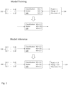
- Figure 1 depicts a diagram providing an overview of the training phase and the inference phase in a neural network.
- pairs of input and known (or desired) output may be provided to train model parameters (also called "weights") of classification model 104.
- train model parameters also called "weights”
- input 102 is a matrix of numbers (which may represent the pixels of an image)
- known output 106 is a vector of classification probabilities (e.g., the probability that the input image is a cat is 1, the probability that the input image is a dog is 0, and the probability that the input image is a human is 0).
- the classification probabilities may be provided by a human (e.g., a human can recognize that the input image depicts a cat and assign the classification probabilities accordingly).
- the model parameters may simply be the parameters that minimize the error between the model's classification (or the model's classification probabilities) of a given set of input with the known classification (or known classification probabilities), while at the same time avoiding "model overfitting".
- classification model 104 In the inference (or prediction or feed-forward) phase, classification model 104 with trained parameters (i.e., parameters trained during the training phase) is used to classify a set of input.
- the trained classification model 104 provides the classification output 110 of a vector of probabilities (e.g., the probability that the input image is a cat is 0.3, the probability that the input image is a dog is 0.6, and the probability that the input image is a human is 0.1) in response to input 108.
- classification model 104 is a convolutional neural network.
- a basic building block of a convolution neural network is a convolution operation, which is described in Figures 2-7 .
- a convolution operation may refer to a 2-dimensional convolution operation with 2-dimensional input and a 2-dimensional filter, a 3-dimensional convolution operation with 3-dimensional input and a 3-dimensional filter, etc.
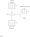
- Figure 2 depicts a diagram of the input, model parameters and output of a 2-dimensional convolution operation.
- the input includes a 2-dimensional matrix of numerical values (each of the numerical values abstractly represented by "•").
- the matrix in the example of Figure 2 is a 4x4 matrix, but other input could have different dimensions (e.g., could be a 100x100 square matrix, a 20x70 rectangular matrix, etc.). Later presented examples will illustrate that the input may even be a 3-dimensional object. In fact, the input may be an object of any number of dimensions.
- the input may represent pixel values of an image or may represent the output of a previous convolution operation.
- the model parameters may include a filter and a bias.
- the filter is a 3x3 matrix of values (the values also called "weights") and the bias is a scalar value.
- weights the values also called "weights”
- the example in Figure 2 includes one filter, so there is one corresponding bias. However, in certain embodiments, if there were 5 filters, there would be 5 associated biases, one for each of the filters.
- the convolution operator 208 receives input 202 and the model parameters 204, 206, and generates output 210 called an activation map or a feature map. Each value of the activation map is generated as the sum of a dot product between of input 202 and filter 204 (at a certain spatial location relative to input 202) and bias 206.
- the computations to arrive at activation map 210 are described in more detail below in Figure 3 .
- the center of filter 204 is spatially aligned with the element at position (1, 1) of input 202.
- Such computation assumes the use of "zero padding" in which the input 202 is implicitly surrounded by a border of zeros.
- zero padding is that the dimensions of input 202 and output activation map 210 remain constant when using a 3x3 filter.
- a dot product is computed between filter 204 and the four values of input 202 that spatially align with filter 204. The dot product is then summed with bias b to arrive at the element at position (1, 1) of activation map 210.
- the second row of Figure 3 describes the computation of the element at position (1, 2) of activation map 210.
- the center of filter 204 is spatially aligned with the element at position (1, 2) of input 202.
- a dot product is computed between filter 204 and the six values of input 202 that spatially align with filter 204.
- the dot product is then summed with bias b to arrive at the element at position (1, 2) of activation map 210.
- the third row of Figure 3 describes the computation of the element at position (1, 3) of activation map 210.
- the center of filter 204 is spatially aligned with the element at position (1, 3) of input 202.
- a dot product is computed between filter 204 and the six values of input 202 that spatially align with filter 204.
- the dot product is then summed with bias b to arrive at the element at position (1, 3) of activation map 210.
- the fourth row of Figure 3 describes the computation of the element at position (4, 4) of activation map 210.
- the center of filter 204 is spatially aligned with the element at position (4, 4) of input 202.
- a dot product is computed between filter 204 and these four values of input 202 that spatially align with filter 204.
- the dot product is then summed with bias b to arrive at the element at position (4, 4) of activation map 210.
- the convolution operation comprises a plurality of shift (or align), dot product and bias (or sum) steps.
- the filter was shifted by 1 spatial position between dot product computations (called the step size or stride), but other step sizes of 2, 3, etc. are possible.
- Figure 4 is similar to Figure 2 , except that there are F filters 404, F biases 406 and F activation maps 410 instead of a single filter 204, a single bias 206 and a single activation map 210.
- the relation between the F filters 404, F biases 406 and F activation maps 410 is as follows: Filter f 1 , bias b 1 and input 402 are used to compute activation map y 1 (in very much the same way that filter 204, bias 206 and input 202 were used to compute activation map 210 in Figure 2 ); filter f 2 , bias b 2 and input 402 are used to compute activation map y 2 ; and so on.
- FIG. 5 is similar to Figure 2 , except that instead of a 2-dimensional input 202 and a 2-dimensional filter 204, a 3-dimensional input 502 and a 3-dimensional filter 504 are used.
- the computations to arrive at activation map 510 are described in more detail below in Figure 6 .
- input 502 and filter 504 are 3-dimensional
- activation map 510 is 2-dimensional, as will become clearer in the associated description of Figure 6 .
- Each "slice" of filter 504 (analogous to a "channel" of input 502) may be called a kernel.
- filter 504 is composed of five kernels
- input 502 is composed of five channels.
- the number of kernels of filter 504 (or the size of the "z" dimension of filter 504) must match the number of channels of input 502 (or the size of the "z” dimension of input 502).
- channel 1 of input 502 aligns with kernel 1 of filter 504;
- channel 2 of input 502 aligns with kernel 2 of filter 504; and so on.
- the central axis 506 of filter 504 (with central axis drawn parallel to the z-axis) is aligned with the elements at positions (1, 1, z) for z ⁇ 1, ..., 5 ⁇ of input 502.
- a dot product is computed between filter 504 and the twenty values of input 502 that spatially align with filter 504 (4 aligned values per channel x 5 channels).
- the dot product is then summed with bias b to arrive at the element at position (1, 1) of activation map 510.
- the second row of Figure 6 describes the computation of the element at position (1, 2) of activation map 510.
- the central axis 506 of filter 504 is aligned with the elements at positions (1, 2, z) for z ⁇ 1, ..., 5 ⁇ of input 502.
- a dot product is computed between filter 504 and the thirty values of input 502 that spatially align with filter 504 (6 aligned values per channel x 5 channels).
- the dot product is then summed with bias b to arrive at the element at position (1, 2) of activation map 510.
- the third row of Figure 6 describes the computation of the element at position (1, 3) of activation map 510.
- the central axis 506 of filter 504 is aligned with the elements at positions (1, 3, z) for z ⁇ 1, ..., 5 ⁇ of input 502.
- a dot product is computed between filter 504 and the thirty values of input 502 that spatially align with filter 504 (6 aligned values per channel x 5 channels).
- the dot product is then summed with bias b to arrive at the element at position (1, 3) of activation map 510.
- the fourth row of Figure 6 describes the computation of the element at position (4, 4) of activation map 510.
- the central axis 506 of filter 504 is aligned with the elements at positions (4, 4, z) for z ⁇ 1, ..., 5 ⁇ of input 502.
- a dot product is computed between filter 504 and the twenty values of input 502 that spatially align with filter 504 (4 aligned values per channel x 5 channels).
- the dot product is then summed with bias b to arrive at the element at position (4, 4) of activation map 510.
- Figure 7 is similar to Figure 5 , except that there are F 3-dimensional filters 704, F biases 706 and F activation maps 710 ( F > 1), instead of a single 3-dimensional filter 504, a single bias 506 and a single activation map 510.
- the relation between the F 3-dimensional filters 704, F biases 706 and F activation maps 710 is as follows: Filter f 1 , bias b 1 and input 702 are used to compute activation map y 1 (in very much the same way that filter 504, bias 506 and input 502 were used to compute activation map 510 in Figure 5 ); filter f 2 , bias b 2 and input 702 are used to compute activation map y 2 ; and so on.
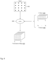
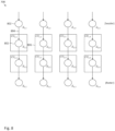
- FIG. 8 depicts convolutional engine 708, in accordance with one embodiment of the invention.
- Convolutional engine 708 (depicted in Figure 8 ) is a hardware architecture of the convolution operator (“conv") 708 (depicted in Figure 7 ).
- Convolutional engine 708 may include a 2-D shift register with an array of data storage elements: d 1 , 1 d 1 , 2 d 1 , 2 d 1 , 4 d 2 , 1 d 2 , 2 d 2 , 3 d 2 , 4 d 3 , 1 d 3 , 2 d 3 , 3 d 3 , 4 d 4 , 1 d 4 , 2 d 4 , 3 d 4 , 4
- the array is a four by four array.
- Each of the data storage elements may be formed by a plurality of D flip-flops (i.e., one D flip-flop to store each bit of a data signal). Therefore, if data storage element d 1,1 were to store eight bits, d 1,1 may be formed from eight D flip-flops.
- Each of the arrows between pairs of data storage elements represents an electrical connection (i.e., may be implemented as a wire). For example, data storage element d 1,1 (ref. num. 802) may be electrically coupled to storage element d 2,1 (ref. num. 802) via electrical connection 804.
- the arrow may represent a one-directional flow of data (i.e., data being transmitted from data storage element d 1,1 to data storage element d 2,1 , but not from d 2,1 to data storage element d 1,1 ).
- data being transmitted from data storage element d 1,1 to data storage element d 2,1 , but not from d 2,1 to data storage element d 1,1 .
- the first row of data storage elements may be called a "header”
- the last row of data storage elements may be called a "footer”.
- n+2 rows within the bolded and dashed rectangle are loaded into convolutional engine 708.
- the n+ 2 rows include a zero padding row, n rows of horizontal stripe 902a and a data padding row (equivalent to row n of horizontal stripe 902b).
- Each of the multipliers is further configured to receive a weight.
- multipliers 2102a, 2102b, 2102c, 2102d, 2102e, 2102f, 2102g, 2102h, and 2102i are configured to receive weights w 1 , w 2 , w 3 , w 4 , w 5 , w 6 , w 7 , w 8 , and w 9 , respectively.
- a different set of weights may be loaded for each channel of input data 702. For example, in the context of Figure 9C , w 1 would equal w 1 1 , 1 ; in the context of Figure 14C , w 1 would equal w 1 1 , 2 ; and so on.
- multipliers 2102a, 2102b, 2102c, 2102d, 2102e, 2102f, 2102g, 2102h, and 2102i may multiply data values x 1 , x 2 , x 3 , x 4 , x 5 , x 6 , x 7 , x 8 , and x 9 with weights w 1 , w 2 , w 3 , w 4 , w 5 , w 6 , w 7 , w 8 , and w 9 so as to generate the products w 1 x 1 , w 2 x 2 , w 3 x 3 , w 4 x 4 , w 5 x 5 , w 6 x 6 , w 7 x 7 , w 8 x 8 , and w 9 x 9 , respectively.
- a specialized multiplier may be implemented using a bit-shifter and an adder (the specialized multiplier further performing a log-to-linear transformation).
- the specialized multiplier further performing a log-to-linear transformation.
- the partial sum is then stored in one of the accumulators 1104a, 1104b, etc. depending on which row of a horizontal stripe the data values are from. If the data values are from row n, the partial sum would be stored in accumulator 1104a; if the data values are from row n-1, the partial sum would be stored in accumulator 1104b; and so on.
- control signal s1 may be set to 1, causing output selector 2106 to deliver a previously computed partial sum to adder 2104h.
- the previously computed partial sum stored in accumulator 1104a would be provided to adder 2104h; if the data values are from row n-1, the previously computed partial sum stored in accumulator 1104b would be provided to adder 2104h; and so on.
- output selector 2106 may be configured to deliver a partial sum from an accumulator to adder 2104j, which sums the partial sum with bias b k .
- the resulting sum may be stored back into the accumulator from which the partial sum was read.
- an entire vector of partial sums may be read from the accumulator array (1104a, 1104b, ...), summed with bias b k , and the vector (now with biasing) may be stored back into the accumulator array.
- Such computation may implement the biasing operation described for CU 1,2 in Figure 20 .
- the computations of all nine multipliers (or their equivalents in the log domain) and nine adders (or their equivalents in the log domain) take place all within one clock cycle. That is, if data values are stored in the nine data storage elements at clock cycle n, the partial sum is stored in the accumulators at clock cycle n+1. Further, for increased throughput, new data values may be stored in the nine data storage elements at clock cycle n+1 while the partial sum is stored. Therefore the computation of a new partial sum may be performed during every clock cycle.
- the stride (or the step size) is the number of pixels or data values that the filter is shifted between dot product operations.
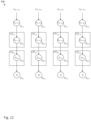
- Figure 22 illustrates that by setting every odd row and every odd column of convolver units to be active and setting every even row and every even column of convolver units to be non-active (by means of control signals provided by controller 2202), a stride of 2 may be achieved. It should be apparent how other stride values can be set.
- rows 3x+1 for x ⁇ ⁇ 0, 1, 2, ... ⁇ of convolver units and columns 3x+1 for x ⁇ ⁇ 0, 1, 2, ... ⁇ of convolver units may be set to be active and all other rows and columns may be set to be non-active. Even strides of less than 1 are possible. For example, for a stride of 1 ⁇ 2, input 702 can be interpolated before it is loaded into convolutional engine 708.
- a 2x2 input matrix of a b c d the following 3x3 interpolated matrix can be provided as input to convolutional engine 708 in order to achieve a stride of 1 ⁇ 2: a a + b 2 b a + c 2 a + b + c + d 4 b + d 2 c c + d 2 d
- a linear interpolation was used in the present example, it is understood that other forms of interpolation (e.g., polynomial interpolation, spline interpolation, etc.) are also possible.
- a convolutional neural network typically involves other types of operations, such as the max pool and rectification operators.
- the convolver unit was presented first for ease of understanding, but now a more generalized form of a convolver unit, called a "functional unit" will now be described for handling other types of operations common in a convolutional neural network in addition to the convolution operation.
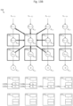
- FIG. 23 depicts convolutional engine 2300 including a 2-D shift register and an array of functional units, in accordance with one embodiment of the invention.
- Convolutional engine 2300 is similar to the above-described convolutional engine 708, except that the convolver units have been replaced with functional units.
- One of the functional unit, FU 1,2 is labeled as 2302 and its hardware architecture is described below in Figure 23 .
- Figure 24 depicts internal components of functional unit 2302, in accordance with one embodiment of the invention. There are two main differences between functional unit 2302 and convolver unit 806. First, functional unit 2302 has the ability to compute the maximum of a sum (needed to perform the max pool operation). Second, functional unit 2302 has the ability to compute the rectification of a value. In order to compute the maximum of a sum, each of the nine adders (2104a, ..., 2104i) of the convolver unit may be replaced with a function selector (2404a, ..., 2404i). The function selector receives control signal s2, allowing the selection between an adder and a comparator (see inset in Figure 24 ).
- the functional unit is transformed back into the hardware architecture of convolver unit 806, and functional unit 2302 is configured to perform the above-described convolution operation.
- functional unit 2302 is configured to compute max( w 1 x 1 , w 2 z 2 , w 3 x 3 , w 4 x 4 , w 5 x 5 , w 6 x 6 , w 7 x 7 , w 8 x 8 , w 9 x 9 ) when control signal s1 is set to 0, and max( w 1 x 1 , w 2 x 2 , w 3 x 3 , w 4 x 4 , w 5 x 5 , w 6 x 6 , w 7 x 7 , w 8 x 8 , w 9 x 9 , previous partial sum) when control signal s1 is set to 1.
- the maximum of the pointwise multiplication of a three dimensional filter (e. g., f 1 ) with a three dimensional volume of input (i.e., a volume of input that aligns with the filter - as described in Figure 6 ) may be computed.
- the max pool operator may be implemented with the comparators of a functional unit selected and the stride set equal to the magnitude of one dimension of a kernel of the filter (e.g., for a 3x3 kernel, the stride would be set to be 3).
- control signal s1 When the control signal s1 is set to 2, functional unit is configured to perform the rectification operation.
- rectifier 2408 can be configured to return 0 whenever the sign bit indicates a negative number or if the zero bit is set, and return the magnitude otherwise.
- control signal s1 When the control signal s1 is set to 3, functional unit is configured to add a bias value to the data stored in accumulators 1104a, 1104b, etc. similar to the operation of convolver unit 806.
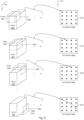
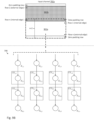
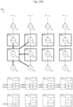
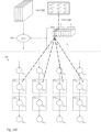
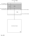
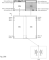
- Figure 25 depicts three scenarios of data values being loaded from input channel 702a into convolutional engine 708 having m columns of convolver units, with scenario (a) illustrating input channel 702a having m columns of data values, scenario (b) illustrating input channel 702a having 3m-4 columns of data values, and scenario (c) illustrating input channel 702a having m / 2 columns of data values, in accordance with one embodiment of the invention.
- Scenario (a) was previously described in Figure 9B , but will be more fully discussed in Figures 26A-26B .
- Scenario (b) discusses an example in which the number of columns of input channel 702a is greater than the number of columns of the convolver array.
- Scenario (c) discusses an example in which the number of columns of input channel 702a is less than the number of columns of the convolver array. While a convolutional engine is more abstractly depicted, it should be understood that the architecture of a convolutional engine may be similar to earlier described examples, with a 2-D shift register and a convolver array.
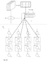
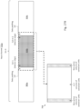
- Figure 26A depicts the loading of a zero padding row, horizontal stripe 902a and a data padding row (corresponding to row n of horizontal stripe 902b) into convolutional engine 708.
- the bolded dashed rectangle denotes the portion of input channel 702a being loaded into convolutional engine 708.
- the zero padding row is first loaded into the 2-D shift register of convolutional engine 708, followed by row n of horizontal stripe 902a, followed by row n-1 of horizontal stripe 902a, ... followed by row 1 of horizontal stripe 902a, and followed by the data padding row.
- each time a row of data storage elements stores row n of a horizontal stripe the convolver units corresponding to that row of data storage elements are activated.
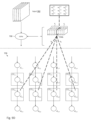
- Figure 26B depicts the loading of one data padding row (corresponding to row 1 of horizontal stripe 902a), horizontal stripe 902b and a zero padding row into convolutional engine 708. More specifically, the data padding row is first loaded into the 2-D shift register of convolutional engine 708, followed by row n of horizontal stripe 902b, followed by row n-1 of horizontal stripe 902b, ... followed by row 1 of horizontal stripe 902b, and followed by the zero padding row.
- While input channel 702a included two horizontal stripes to illustrate the concept of a single "horizontal cut line" through the input data (conceptually located at the boundary of horizontal stripes 902a and 902b), it is understood that an input channel would have more horizontal stripes if there were more horizontal cut lines. For a horizontal stripe that is bordered above and below by other horizontal stripes, the loading of that horizontal stripe would be preceded by a data padding row and followed by another data padding row.
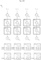
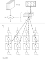
- Figures 27A-27C illustrate a scenario in which "vertical cut lines" through input channel 702a are needed, and how to handle the vertical cut lines.
- a vertical cut line is needed whenever the number of columns of the input channel is greater than the number of columns of the convolver array.
- the present example discusses the scenario in which the number of columns of the input channel is equal to 3m-4, where m is the number of columns of the convolver array.
- the convolver array is utilized in an efficient manner (no unused convolver units), but if this relationship does not hold, the concepts described below still apply, but the convolver array will be utilized in a less efficient manner (will have unused convolver units).
- horizontal cut lines, zero padding rows, data padding rows are not discussed in the example of Figures 27A-27C . Nevertheless, it is expected that one of ordinary skill in the art will be able to combine concepts from Figures 26A-26B and 27A-27B in order to handle scenarios in which there are both horizontal and vertical cut lines.
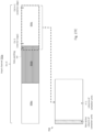
- Figure 27B depicts m columns (including the m-2 columns of vertical stripe 906b bordered on the right and left sides by a data padding column) being loaded into convolutional engine 708.
- the left most and right most columns of convolver units (which align with the data padding columns) are non-active, for reasons similar to those provided above.
- the remaining m-2 columns of the convolver units operate in a similar manner as the convolver units that have been previously described.
Landscapes
- Engineering & Computer Science (AREA)
- Physics & Mathematics (AREA)
- Theoretical Computer Science (AREA)
- General Physics & Mathematics (AREA)
- Mathematical Physics (AREA)
- General Engineering & Computer Science (AREA)
- Data Mining & Analysis (AREA)
- Software Systems (AREA)
- Computing Systems (AREA)
- Biophysics (AREA)
- Biomedical Technology (AREA)
- Life Sciences & Earth Sciences (AREA)
- Health & Medical Sciences (AREA)
- Computational Linguistics (AREA)
- Evolutionary Computation (AREA)
- Artificial Intelligence (AREA)
- Molecular Biology (AREA)
- General Health & Medical Sciences (AREA)
- Mathematical Analysis (AREA)
- Computational Mathematics (AREA)
- Mathematical Optimization (AREA)
- Pure & Applied Mathematics (AREA)
- Neurology (AREA)
- Algebra (AREA)
- Databases & Information Systems (AREA)
- Complex Calculations (AREA)
- Lubrication Of Internal Combustion Engines (AREA)
- Image Processing (AREA)
- Image Analysis (AREA)
Abstract
Description
- This application claims priority to
U.S. Provisional Application No. 62/642,578, filed 13 March 2018 U.S. Provisional Application No. 62/694,290, filed 5 July 2018 - The present invention relates to a hardware architecture for a convolutional engine, and more particularly relates to an efficient way to provide data values to compute units (called convolver units or functional units) of the convolutional engine.
- Today, neural networks (in particular convolution neural networks) are widely used for performing image recognition/classification, object recognition/classification and image segmentation. While having numerous applications (e.g., object identification for self-driving cars, facial recognition for social networks, etc.), neural networks require intensive computational processing and frequent memory accesses. Described herein is an efficient hardware architecture for implementing a convolutional neural network.
-
-
Figure 1 depicts a diagram providing an overview of model training and model application in a neural network. -
Figure 2 depicts a diagram of the input, model parameters and output of a convolution operation, the model parameters including a single 2-dimensional filter. -
Figure 3 depicts a diagram that explains the computation of a convolution operation using a 2-dimensional filter. -
Figure 4 depicts a diagram of the input, model parameters and output of a convolution operation, the model parameters including a plurality of 2-dimensional filters. -
Figure 5 depicts a diagram of the input, model parameters and output of a convolution operation, the model parameters including a single 3-dimensional filter. -
Figure 6 depicts a diagram that explains the computation of a convolution operation using a 3-dimensional filter. -
Figure 7 depicts a diagram of the input, model parameters and output of a convolution operation, the model parameters including a plurality of 3-dimensional filters. -
Figure 8 depicts a convolutional engine including a 2-D shift register and an array of convolver units, in accordance with one embodiment of the invention. -
Figures 9A-9B depict the loading of data values into the convolutional engine, in accordance with one embodiment of the invention. -
Figures 9C-9D depict the loading of filter weights into the convolutional engine, in accordance with one embodiment of the invention. -
Figures 10A-10B depict the loading of a zero padding row into the 2-D shift register, in accordance with one embodiment of the invention. -
Figures 10B-10D depict the loading of data values into the 2-D shift register, in accordance with one embodiment of the invention. -
Figures 11A and11B describe the processing of two convolver units for the spatial orientation of the data values depicted inFigure 10D , in accordance with one embodiment of the invention. -
Figure 11C depicts the resulting partial sums following the processing of all active convolver units for the spatial orientation of the data values depicted inFigure 10D , in accordance with one embodiment of the invention. -
Figure 12 depicts the data values after they have been shifted down one row of the 2-D shift register, as compared to the spatial orientation of the data values depicted inFigure 10D . -
Figures 13A-13D describe the processing of four convolver units for the spatial orientation of the data values depicted inFigure 12 , in accordance with one embodiment of the invention. -
Figure 13E depicts the resulting partial sums following the processing of all active convolver units for the spatial orientation of the data values depicted inFigure 12 , in accordance with one embodiment of the invention. -
Figures 14A-14B depict the loading of data values into the convolutional engine, in accordance with one embodiment of the invention. -
Figures 14C-14D depict the loading of filter weights into the convolutional engine, in accordance with one embodiment of the invention. -
Figures 15A-15B depict the loading of a zero padding row into the 2-D shift register, in accordance with one embodiment of the invention. -
Figures 15B-15D depict the loading of data values into the 2-D shift register, in accordance with one embodiment of the invention. -
Figures 16A-16B describe the processing of two convolver units for the spatial orientation of the data values depicted inFigure 15D , in accordance with one embodiment of the invention. -
Figure 16C depicts the resulting partial sums following the processing of all active convolver units for the spatial orientation of the data values depicted inFigure 15D , in accordance with one embodiment of the invention. -
Figure 17 depicts the data values after they have been shifted down one row of the 2-D shift register as compared to the spatial orientation of the data values depicted inFigure 15D . -
Figures 18A-18B describe the processing of two convolver units for the spatial orientation of the data values depicted inFigure 17 , in accordance with one embodiment of the invention. -
Figure 18C depicts the resulting partial sums following the processing of all active convolver units for the spatial orientation of the data values depicted inFigure 17 , in accordance with one embodiment of the invention. -
Figures 19A-9B depict the loading of bias values into the convolutional engine, in accordance with one embodiment of the invention. -
Figure 20 depicts the output of each of the convolver units, after the partial sums have been biased with bias values, in accordance with one embodiment of the invention. -
Figure 21 depicts internal components of a convolver unit, in accordance with one embodiment of the invention. -
Figure 22 depicts control circuitry for controlling the stride of a convolution operation, in accordance with one embodiment of the invention. -
Figure 23 depicts a generalized convolutional engine including a 2-D shift register and an array of functional units, in accordance with one embodiment of the invention. -
Figure 24 depicts internal components of a functional unit, in accordance with one embodiment of the invention. -
Figure 25 depicts three scenarios of data values being loaded from an input channel into a convolutional engine having m columns of convolver units, with scenario (a) illustrating the input channel having m columns of data values, scenario (b) illustrating the input channel having 3m-4 columns of data values, and scenario (c) illustrating the input channel having m/2 columns of data values, in accordance with one embodiment of the invention. -
Figures 26A-26B depict the loading of data values into the convolutional engine for scenario (a), in accordance with one embodiment of the invention. -
Figures 27A-27C depict the loading of data values into the convolutional engine for scenario (b), in accordance with one embodiment of the invention. -
Figure 28 depicts the loading of data values into the convolutional engine for scenario (c), in accordance with one embodiment of the invention. -
Figures 29A-29B depict an alternate scheme for loading data values into the convolutional engine for scenario (c), in accordance with one embodiment of the invention. -
Figure 30 depicts a convolutional engine as one component of a larger system, in accordance with one embodiment of the invention. -
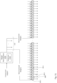
Figure 31 depicts a block diagram of a component for decompressing filter weights before the weights are provided to the convolver units, in accordance with one embodiment of the invention. - In the following detailed description of the preferred embodiments, reference is made to the accompanying drawings that form a part hereof, and in which are shown by way of illustration specific embodiments in which the invention may be practiced. It is understood that other embodiments may be utilized and structural changes may be made without departing from the scope of the present invention. Description associated with any one of the figures may be applied to a different figure containing like or similar components/steps.
-
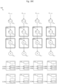
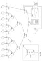
Figure 1 depicts a diagram providing an overview of the training phase and the inference phase in a neural network. In the training phase, pairs of input and known (or desired) output may be provided to train model parameters (also called "weights") ofclassification model 104. For conciseness, only one input and output pair (102, 106) is depicted inFigure 1 , but in practice many known input and output pairs will be used to trainclassification model 104. In the example ofFigure 1 ,input 102 is a matrix of numbers (which may represent the pixels of an image) andknown output 106 is a vector of classification probabilities (e.g., the probability that the input image is a cat is 1, the probability that the input image is a dog is 0, and the probability that the input image is a human is 0). In one possible training process, the classification probabilities may be provided by a human (e.g., a human can recognize that the input image depicts a cat and assign the classification probabilities accordingly). At the conclusion of the model training process, the model parameters will have been estimated (e.g., W1 = 1.2, W2 = 3.8, W3 = 2.7). Sometimes, there may be intuitive ways to interpret the model parameters, but many times no intuition may be associated therewith, and the model parameters may simply be the parameters that minimize the error between the model's classification (or the model's classification probabilities) of a given set of input with the known classification (or known classification probabilities), while at the same time avoiding "model overfitting". - In the inference (or prediction or feed-forward) phase,
classification model 104 with trained parameters (i.e., parameters trained during the training phase) is used to classify a set of input. In the instant application, the trainedclassification model 104 provides theclassification output 110 of a vector of probabilities (e.g., the probability that the input image is a cat is 0.3, the probability that the input image is a dog is 0.6, and the probability that the input image is a human is 0.1) in response toinput 108. - One embodiment of
classification model 104 is a convolutional neural network. A basic building block of a convolution neural network is a convolution operation, which is described inFigures 2-7 . As further described below, a convolution operation may refer to a 2-dimensional convolution operation with 2-dimensional input and a 2-dimensional filter, a 3-dimensional convolution operation with 3-dimensional input and a 3-dimensional filter, etc. -
Figure 2 depicts a diagram of the input, model parameters and output of a 2-dimensional convolution operation. In the example ofFigure 2 , the input includes a 2-dimensional matrix of numerical values (each of the numerical values abstractly represented by "•"). The matrix in the example ofFigure 2 is a 4x4 matrix, but other input could have different dimensions (e.g., could be a 100x100 square matrix, a 20x70 rectangular matrix, etc.). Later presented examples will illustrate that the input may even be a 3-dimensional object. In fact, the input may be an object of any number of dimensions. The input may represent pixel values of an image or may represent the output of a previous convolution operation. - The model parameters may include a filter and a bias. In the example of
Figure 2 , the filter is a 3x3 matrix of values (the values also called "weights") and the bias is a scalar value. Typically, there is one bias associated with each filter. The example inFigure 2 includes one filter, so there is one corresponding bias. However, in certain embodiments, if there were 5 filters, there would be 5 associated biases, one for each of the filters. - The convolution operator 208 (abbreviated "conv") receives
input 202 and themodel parameters output 210 called an activation map or a feature map. Each value of the activation map is generated as the sum of a dot product between ofinput 202 and filter 204 (at a certain spatial location relative to input 202) andbias 206. The computations to arrive atactivation map 210 are described in more detail below inFigure 3 . - The first row of
Figure 3 describes the computation of the element at position (x=1, y=1) ofactivation map 210. As shown in the first row, the center offilter 204 is spatially aligned with the element at position (1, 1) ofinput 202. Such computation assumes the use of "zero padding" in which theinput 202 is implicitly surrounded by a border of zeros. The advantage of using zero padding is that the dimensions ofinput 202 andoutput activation map 210 remain constant when using a 3x3 filter. A dot product is computed betweenfilter 204 and the four values ofinput 202 that spatially align withfilter 204. The dot product is then summed with bias b to arrive at the element at position (1, 1) ofactivation map 210. - The second row of
Figure 3 describes the computation of the element at position (1, 2) ofactivation map 210. As shown in the second row, the center offilter 204 is spatially aligned with the element at position (1, 2) ofinput 202. A dot product is computed betweenfilter 204 and the six values ofinput 202 that spatially align withfilter 204. The dot product is then summed with bias b to arrive at the element at position (1, 2) ofactivation map 210. - The third row of
Figure 3 describes the computation of the element at position (1, 3) ofactivation map 210. As shown in the third row, the center offilter 204 is spatially aligned with the element at position (1, 3) ofinput 202. A dot product is computed betweenfilter 204 and the six values ofinput 202 that spatially align withfilter 204. The dot product is then summed with bias b to arrive at the element at position (1, 3) ofactivation map 210. - The fourth row of
Figure 3 describes the computation of the element at position (4, 4) ofactivation map 210. As shown in the fourth row, the center offilter 204 is spatially aligned with the element at position (4, 4) ofinput 202. A dot product is computed betweenfilter 204 and these four values ofinput 202 that spatially align withfilter 204. The dot product is then summed with bias b to arrive at the element at position (4, 4) ofactivation map 210. In general, the convolution operation comprises a plurality of shift (or align), dot product and bias (or sum) steps. In the present example, the filter was shifted by 1 spatial position between dot product computations (called the step size or stride), but other step sizes of 2, 3, etc. are possible. -
Figure 4 is similar toFigure 2 , except that there areF filters 404,F biases 406 and F activation maps 410 instead of asingle filter 204, asingle bias 206 and asingle activation map 210. The relation between the F filters 404,F biases 406 and F activation maps 410 is as follows: Filter f1 , bias b1 andinput 402 are used to compute activation map y1 (in very much the same way that filter 204,bias 206 andinput 202 were used to computeactivation map 210 inFigure 2 ); filter f2, bias b2 andinput 402 are used to compute activation map y2 ; and so on. -
Figure 5 is similar toFigure 2 , except that instead of a 2-dimensional input 202 and a 2-dimensional filter 204, a 3-dimensional input 502 and a 3-dimensional filter 504 are used. The computations to arrive atactivation map 510 are described in more detail below inFigure 6 . Whileinput 502 and filter 504 are 3-dimensional,activation map 510 is 2-dimensional, as will become clearer in the associated description ofFigure 6 . Each "slice" of filter 504 (analogous to a "channel" of input 502) may be called a kernel. InFigure 5 ,filter 504 is composed of five kernels, andinput 502 is composed of five channels. If not already apparent, the number of kernels of filter 504 (or the size of the "z" dimension of filter 504) must match the number of channels of input 502 (or the size of the "z" dimension of input 502). During a convolution operation,channel 1 ofinput 502 aligns withkernel 1 offilter 504;channel 2 ofinput 502 aligns withkernel 2 offilter 504; and so on. Typically, there is no translation offilter 504 with respect toinput 502 in the z-dimension during a convolution operation. - The first row of
Figure 6 describes the computation of the element at position (x=1, y=1) ofactivation map 510. As shown in the first row, thecentral axis 506 of filter 504 (with central axis drawn parallel to the z-axis) is aligned with the elements at positions (1, 1, z) for z∈{1, ..., 5} ofinput 502. A dot product is computed betweenfilter 504 and the twenty values ofinput 502 that spatially align with filter 504 (4 aligned values per channel x 5 channels). The dot product is then summed with bias b to arrive at the element at position (1, 1) ofactivation map 510. - The second row of
Figure 6 describes the computation of the element at position (1, 2) ofactivation map 510. As shown in second first row, thecentral axis 506 offilter 504 is aligned with the elements at positions (1, 2, z) for z∈{1, ..., 5} ofinput 502. A dot product is computed betweenfilter 504 and the thirty values ofinput 502 that spatially align with filter 504 (6 aligned values per channel x 5 channels). The dot product is then summed with bias b to arrive at the element at position (1, 2) ofactivation map 510. - The third row of
Figure 6 describes the computation of the element at position (1, 3) ofactivation map 510. As shown in the third row, thecentral axis 506 offilter 504 is aligned with the elements at positions (1, 3, z) for z∈{1, ..., 5} ofinput 502. A dot product is computed betweenfilter 504 and the thirty values ofinput 502 that spatially align with filter 504 (6 aligned values per channel x 5 channels). The dot product is then summed with bias b to arrive at the element at position (1, 3) ofactivation map 510. - The fourth row of
Figure 6 describes the computation of the element at position (4, 4) ofactivation map 510. As shown in the fourth row, thecentral axis 506 offilter 504 is aligned with the elements at positions (4, 4, z) for z∈{1, ..., 5} ofinput 502. A dot product is computed betweenfilter 504 and the twenty values ofinput 502 that spatially align with filter 504 (4 aligned values per channel x 5 channels). The dot product is then summed with bias b to arrive at the element at position (4, 4) ofactivation map 510. -
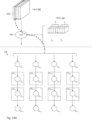
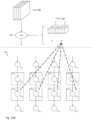
Figure 7 is similar toFigure 5 , except that there are F 3-dimensional filters 704,F biases 706 and F activation maps 710 (F > 1), instead of a single 3-dimensional filter 504, asingle bias 506 and asingle activation map 510. The relation between the F 3-dimensional filters 704,F biases 706 and F activation maps 710 is as follows: Filter f1 , bias b1 andinput 702 are used to compute activation map y1 (in very much the same way that filter 504,bias 506 andinput 502 were used to computeactivation map 510 inFigure 5 ); filter f2 , bias b2 andinput 702 are used to compute activation map y2 ; and so on. - The following figures describe a hardware architecture to perform the convolution operation of
Figure 7 . Many of the examples assume the use of two filters, F = 2, for simplicity. The examples further assume that thefilters 704 are constructed using 3x3 kernels (i.e., each kernel being composed of 9 weights). It is understood, however, that the concepts/architectures described herein can be modified to accommodate kernels with other dimensions. -
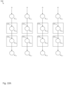
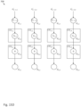
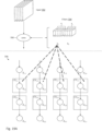
Figure 8 depictsconvolutional engine 708, in accordance with one embodiment of the invention. Convolutional engine 708 (depicted inFigure 8 ) is a hardware architecture of the convolution operator ("conv") 708 (depicted inFigure 7 ).Convolutional engine 708 may include a 2-D shift register with an array of data storage elements:
Figure 8 , the array is a four by four array. Each of the data storage elements may be formed by a plurality of D flip-flops (i.e., one D flip-flop to store each bit of a data signal). Therefore, if data storage element d 1,1 were to store eight bits, d 1,1 may be formed from eight D flip-flops. Each of the arrows between pairs of data storage elements represents an electrical connection (i.e., may be implemented as a wire). For example, data storage element d 1,1 (ref. num. 802) may be electrically coupled to storage element d 2,1 (ref. num. 802) viaelectrical connection 804. Further, the arrow may represent a one-directional flow of data (i.e., data being transmitted from data storage element d 1,1 to data storage element d 2,1, but not from d 2,1 to data storage element d 1,1). In the discussion that follows, the first row of data storage elements may be called a "header", and the last row of data storage elements may be called a "footer". -
Convolutional engine 708 may further include an array of convolver units: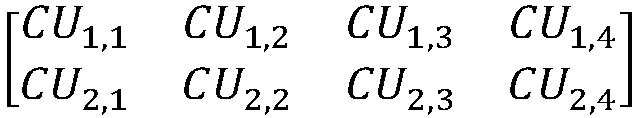
- For conciseness, an array of convolver units may be called "a convolver array". In the simplified example of
Figure 8 , the convolver array is a two by four array. Convolver unit CU 1,2 has been labeled with reference numeral 806 (to facilitate later discussion). It is understood that a more typical embodiment will contain many more convolver units, such as in the example embodiment ofFigure 30 . The operation of the 2-D shift register and the operation of the convolver units will be described in detail in the following figures. -
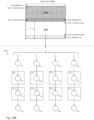
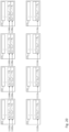
Figure 9A depicts the loading of data values intoconvolutional engine 708, in accordance with one embodiment of the invention. Each channel of input may be loaded intoconvolutional engine 708 in a serial fashion.Figure 9A depicts the loading of thefirst channel 702a ofinput 702 into convolutional engine 708 (assuming that the channels are numbered from 1 to 5 in the left to right direction). As will be described inFigures 10B-10D , the rows of a particular channel may be loaded intoconvolutional engine 708 in a serial fashion. It is noted that terms such as a "row" and a "column" will be/are being used for convenience and with respect to how elements are depicted in the figures. Nevertheless, the meaning of such terms may or may not translate into how circuit elements are laid out on a chip, where a row could be interpreted as a column and vice versa, depending on the viewer's orientation with respect to the chip. - For simplicity, this first example describing the hardware architecture of a convolutional engine will handle the case in which the number of columns of an input channel is equal to the number of columns of the convolver array. In
Figure 9B , the number of columns ofinput channel 702a is assumed to equal the number of columns of the convolver array. For instance,input channel 702a may be a ten by four matrix of data values.Figures 27A-27C describe how to handle the scenario in which the number of columns of an input channel is greater than the number of columns of the convolver array.Figures 28 ,29A and29B describe two schemes for handling the case in which the number of columns of an input channel is less than the number of columns of the convolver array. - Typically, due to memory constraints of each convolver unit,
convolutional engine 708 can only compute the convolution operation for a certain number of contiguous rows of the data values before the output needs to be saved (copied to a memory location separate from the convolver units - see memory 3002 inFigure 30 ). Once the output is saved, theconvolutional engine 708 can continue onto the next set of contiguous rows. In particular, if each convolver unit is constructed with n accumulators,convolution engine 708 can compute the output of n contiguous input rows (plus two padding rows explained below). For simplicity of explanation, n contiguous input rows will be called a "horizontal stripe" of data. In the simplified example ofFigure 9B , there are twohorizontal stripes convolutional engine 708 may process the horizontal stripes serially. In the example ofFigure 9B ,horizontal stripe 902a is processed first, followed byhorizontal stripe 902b. - For reasons that will be more apparent below, the loading of a leading row (i.e., first row of a horizontal stripe to be loaded) that is an external edge may be preceded by the loading of a zero padding row (as in row n of
horizontal stripe 902a); the loading of a trailing row (i.e., last row of a horizontal stripe to be loaded) that is an external edge may be followed by the loading of a zero padding row (as inrow 1 ofhorizontal stripe 902b); the loading of a leading row that is an internal edge may be preceded by the loading of a data padding row (as in row n ofhorizontal stripe 902b); and the loading of a trailing row that is an internal edge may be followed by the loading of a data padding row (as inrow 1 ofhorizontal stripe 902a). If not already apparent, an "external edge" refers to a leading or trailing row of a horizontal stripe that forms an external boundary of an input channel, whereas an internal edge refers to a leading or trailing row of a horizontal stripe that is not part of an external boundary of an input channel. The reason for the zero or data padding row is tied to the 3x3 filter requiring data from a row above and a row below the row of interest to compute the convolution output. For a 5x5 filter, two padding rows (for the top row of a stripe) and two padding rows (for the bottom row of a stripe) or a total of four padding rows would have been needed. - In the particular example of
Figure 9B , the n+2 rows within the bolded and dashed rectangle are loaded intoconvolutional engine 708. The n+2 rows include a zero padding row, n rows ofhorizontal stripe 902a and a data padding row (equivalent to row n ofhorizontal stripe 902b). -
Figures 9C-9D depict the loading of filter weights toconvolutional engine 708, in accordance with one embodiment of the invention. More specifically,Figure 9C depicts the loading of the nine weights of kernel 704a into each of the convolver units of the first row of the convolver array (i.e., CU 1,1 , CU 1,2 , CU 1,3 and CU 1,4 ), andFigure 9D depicts the loading of the nine weights ofkernel 704b into each of the convolver units of the second row of the convolver array (i.e., CU 2,1 , CU 2,2 , CU 2,3 and CU 2,4). Kernel 704a is the first kernel of filter f1, and each of its weights is labeled with the superscript "1,1", which is shorthand for (filter f1, kernel 1).Kernel 704b is the first kernel of filter f2, and each of its weights is labeled with the superscript "2,1", which is shorthand for (filter f2 , kernel 1). -
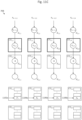
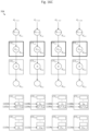
Figures 10A-10B depict the loading of a row of zero values into the 2-D shift register.Figures 10B-10D depict a row-by-row loading of data values from thefirst input channel 702a into the 2-D shift register and a row-to-row shifting of the data values through the 2-D shift register. Data values x n,1, x n,2, x n,3 and x n,4 may represent values from row n ofhorizontal stripe 902a ofinput channel 702a. Data values x n-1,1, x n-1,2, x n-1,3 and x n-1,4 may represent values from row n-1 ofhorizontal stripe 902a ofinput channel 702a. Data values x n-2,1, x n-2,2, x n-2,3 and x n-2,4 may represent values from row n-2 ofhorizontal stripe 902a ofinput channel 702a. - Upon row n of
horizontal stripe 902a being loaded into the second row of data storage elements (i.e., d 2,1, d 2,2, d 2,3 and d 2,4), the first row of convolver units (i.e., CU 1,1 , CU 1,2 , CU 1,3 and CU 1,4) corresponding to the second row of data storage elements may be activated. By "corresponding", it is meant that there is a logical correspondence between convolver unit CU 1,1 and data storage element d 2,1, convolver unit CU 1,2 and data storage element d 2,2, and so on. The correspondences between the data storage element and convolver units are shown in the figures by the data storage element being drawn within the corresponding convolver unit. In a more typical embodiment with a high number of convolver units, most of the convolver units will receive data values from its corresponding data storage element and eight spatial neighbors (i.e., data storage element neighbors) of the corresponding data storage element. Such relationship is more difficult to appreciate from the example convolutional engine ofFigure 11A in which there is a small number of convolver units. - Active convolver units are drawn in
Figure 11A in bolded lines while non-active convolver units are drawn inFigure 11A using non-bolded lines. In one embodiment, "active" means that a convolver unit is powered on, whereas "non-active" means that a convolver unit is powered off to save power. A controller (depicted as controller 2202 inFigure 22 andcontroller 3006 inFigure 30 , but not depicted in other figures for conciseness of presentation) may be responsible for powering on and off convolver units. The controller may power on a row of convolver units once the data from row n of a horizontal stripe has been loaded into the data storage elements corresponding to the row of convolver units. The controller may power off a row of convolver units once data fromrow 1 of a horizontal stripe has been transferred out of the data storage elements corresponding to the row of convolver units. -
Figures 11A and11B describe the processing of two out of the four active convolver units for the spatial orientation of the data values depicted inFigure 10D . While the processing of the two convolver units is described in two separate figures, it is understood that such processing typically occurs in parallel (i.e., at the same time) in order to increase the number of computations per clock cycle. - As depicted in
Figure 11A , convolver unit CU 1,1 (typical for convolver units located on the left and right edges of the convolver array) receives data and/or zero values from five neighboring data storage elements and one data value from the data storage element corresponding to convolver unit CU 1,1 . More specifically, convolver unit CU 1,1 receives: - ➢ data value x n-1,1 from data storage element d 1,1 via
electrical connection 1100a, - ➢ data value x n-1,2 from data storage element d 1,2 via
electrical connection 1100b, - ➢ data value x n,1 from data storage element d 2,1 via an electrical connection (not depicted)
- ➢ data value x n,2 from data storage element d 2,2 via electrical connection 1100c,
- > the zero value from data storage element d 3,1 via
electrical connection 1100d, and - ➢ the zero value from data storage element d 3,2 via electrical connection 1100e.
- Once the data and/or zero values have been received, convolver unit CU 1,1 may compute the partial sum y1 defined by


Figure 9C ) and store the partial sum y 1 inaccumulator 1102a of convolver unit CU 1,1 .Accumulator 1102a may be part of a linear array of n accumulators, where n is the number of rows of withinhorizontal stripe 902a.Accumulator 1102a may be configured to store the partial sums corresponding to row n of a horizontal stripe;accumulator 1102b may be configured to store the partial sums corresponding to row n-1 of a horizontal stripe; and so on. For clarity of explanation, it is noted that the bottom instance of convolver unit CU 1,1 and the top instance of convolver unit CU 1,1 are one and the same convolver unit, with the bottom instance showing additional details of the top instance. - As depicted in
Figure 11B , convolver unit CU 1,2 receives data and/or zero values from eight neighboring data storage elements and one data value from the data storage element corresponding to convolver unit CU 1,2 . More specifically, convolver unit CU 1,2 receives: - ➢ data value x n-1,1 from data storage element d 1,1 via
electrical connection 1100f, - ➢ data value x n-1,2 from data storage element d 1,2 via
electrical connection 1100g, - ➢ data value x n-1,3 from data storage element d 1,3 via
electrical connection 1100h, - ➢ data value x n,1 from data storage element d 2,1 via an
electrical connection 1100i, - ➢ data value x n,2 from data storage element d 2,2 via electrical connection (not depicted),
- ➢ data value x n,3 from data storage element d 2,3 via
electrical connection 1100j, - ➢ the zero value from data storage element d 3,1 via
electrical connection 1100k, - ➢ the zero value from data storage element d 3,2 via electrical connection 1100l, and
- ➢ the zero value from data storage element d 3,3 via
electrical connection 1100m. - Once the data values have been received, convolver unit CU 1,2 may compute the partial sum y 2 defined by


Figure 9C ) and store the partial sum y 2 inaccumulator 1104a of convolver unit CU 1,2. - Similar processing is performed by CU 1,3 and CU 1,4 , so the details of these computations have been omitted for conciseness. At the conclusion of the processing by the four active convolver units for the spatial orientation of data values shown in
Figure 10D , four partial sums are computed and stored inaccumulators Figure 11C . -
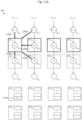
Figure 12 depicts the 2-D shift register after the data and/or zero values have been shifted down one row of data storage elements, and data values x n-2,1, x n-2,2, x n-2,3 and x n-2,4 from the n-2 row of thehorizontal stripe 902a have been loaded into the 2-D shift register. Once row n ofhorizontal stripe 902a has been loaded into data storage elements d 3,1, d 3,2, d 3,3, and d 3,4, the corresponding convolver units CU 2,1 , CU 2,2 , CU 2,3 and CU 2,4 are activated, in addition to CU 1,1 , CU 1,2 , CU 1,3 and CU 1,4 (as shown inFigure 13A ). -
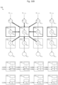
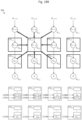
Figures 13A-13D describe the processing of four of the eight active convolver units, in accordance with one embodiment of the invention. While the processing of the four convolver units is described in four separate figures, it is understood that such processing typically occurs in parallel (i.e., at the same time) in order to increase the number of computations per clock cycle. - As depicted in
Figure 13A , convolver unit CU 1,1 may receive data values from the five neighboring data storage elements and the one corresponding data storage element. Convolver unit CU 1,1 may compute the partial sum y 5 defined by

accumulator 1102b of convolver unit CU 1,1 . - As depicted in
Figure 13B , convolver unit CU 1,2 may receive data values from the eight neighboring data storage elements and the one corresponding data storage element. Convolver unit CU 1,2 may compute the partial sum y6 defined by

accumulator 1104b of convolver unit CU 1,2. - As depicted in
Figure 13C , convolver unit CU 1,3 may receive data values from the eight neighboring data storage elements and the one corresponding data storage element. Convolver unit CU 1,3 may compute the partial sum y7 defined by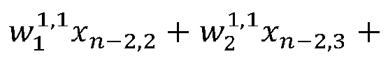

accumulator 1106b of convolver unit CU 1,3 . - As depicted in
Figure 13D , convolver unit CU 2,1 may receive data and/or zero values from the five neighboring data storage elements and the one corresponding data storage element. Convolver unit CU 2,1 may then compute the partial sum y 9 defined by


kernel 704b depicted inFigure 9D ) and store the partial sum y9 inaccumulator 1110a of convolver unit CU 2,1 . - Similar processing may be performed by CU 1,4 , CU 2,2 , CU 2,3 and CU 2,4 , so the details of these computations have been omitted for conciseness. At the conclusion of the processing by the active convolver units for the spatial orientation of data values shown in
Figure 12 , eight (additional) partial sums have been computed and stored inaccumulators Figure 13E . - The processing of the 2-D shift register and the plurality of convolutional units continues in a similar fashion until
row 1 ofhorizontal stripe 902a has been shifted through the 2-D shift register. At this point, data values of the next input channel and parameters (i.e., weights) of the kernels corresponding to the next input channel may be loaded into the convolutional engine, as depicted inFigures 14A-14D . -
Figure 14A depicts the loading of data values from thesecond input channel 702b intoconvolutional engine 708, in accordance with one embodiment of the invention. As depicted in greater detail inFigure 14B , thesecond input channel 702b may includehorizontal stripes 904a and 904b, andhorizontal stripe 904a may be loaded intoconvolutional engine 708 in a similar manner ashorizontal stripe 902a was loaded. -
Figures 14C-14D depict the loading of filter weights intoconvolutional engine 708, in accordance with one embodiment of the invention. More specifically,Figure 14C depicts the loading of the nine weights ofkernel 704c into each of the convolver units of the first row of the convolver array (i.e., CU 1,1 , CU 1,2 , CU 1,3 and CU 1,4), andFigure 14D depicts the loading of the nine weights ofkernel 704b into each of the convolver units of the second row of the convolver array (i.e., CU 2,1 , CU 2,2 , CU 2,3 and CU 2,4).Kernel 704c is the second kernel of filter f1, and each of its weights is labeled with the superscript "1,2", which is shorthand for (filter f1, kernel 2).Kernel 704d is the second kernel of filter f2, and each of its weights is labeled with the superscript "2,2", which is shorthand for (filter f2 , kernel 2). -
Figures 15A-15B depict the loading of a row of zero values into the 2-D shift register.Figures 15B-15D depict a row-by-row loading of data values from thesecond input channel 702b into the 2-D shift register and a row-to-row shifting of the data values through the 2-D shift register. Data values

horizontal stripe 904a ofinput channel 702b. Data values

horizontal stripe 904a ofinput channel 702b. Data values

horizontal stripe 904a ofinput channel 702b. Upon row n ofhorizontal stripe 904a being loaded into the second row of data storage elements, the first row of convolver units may be activated (as shown inFigure 16A ). -
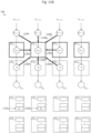
Figures 16A and16B describe the processing of two out of the four active convolver units for the spatial orientation of the data values depicted inFigure 15D . As depicted inFigure 16A , convolver unit CU 1,1 may receive data and/or zero values from the five neighboring data storage elements and one data value from the data storage element corresponding to convolver unit CU 1,1 . Once the data values have been received, convolver unit CU 1,1 may compute the partial sum y13 defined by


kernel 704c depicted inFigure 14C ). The partial sum y 13 may be summed with y 1 (the partial sum previously computed by convolver unit CU 1,1 for row n) and the new partial sum y 1 + y13 may be stored inaccumulator 1102a. - As depicted in
Figure 16B , convolver unit CU 1,2 may receive data and/or zero values from the eight neighboring data storage elements and one data value from the data storage element corresponding to convolver unit CU 1,2 . Once the data and/or zero values have been received, convolver unit CU 1,2 may compute the partial sum y14 defined by


kernel 704c depicted inFigure 14C ). The partial sum y 14 may be summed with y 2 (the partial sum previously computed by convolver unit CU 1,2 for row n) and the new partial sum y 2 + y14 may be stored inaccumulator 1104a. - Similar processing is performed by CU 1,3 and CU 1,4 , so the details of these computations have been omitted for conciseness. At the conclusion of the processing by the four active convolver units for the spatial orientation of data values shown in
Figure 15D , four partial sums have been updated and stored inaccumulators Figure 16C . -
Figure 17 depicts the 2-D shift register after the data and/or zero values have been shifted down one row of data storage elements, and data values

horizontal stripe 904a have been loaded into the 2-D shift register. Once row n ofhorizontal stripe 904a has been loaded into data storage elements d 3,1, d 3,2, d 3,3 and d 3,4, the corresponding convolver units CU 2,1 , CU 2,2 , CU 2,3 and CU 2,4 are activated, in addition to CU 1,1 , CU 1,2 , CU 1,3 and CU 1,4 (as shown inFigure 18A ). -
Figures 18A-18B describe the processing of two of the eight active convolver units, in accordance with one embodiment of the invention. As depicted inFigure 18A , convolver unit CU 1,1 may receive data values from the five neighboring data storage elements and the one corresponding data storage element. Convolver unit CU 1,1 may then compute the partial sum y 17 defined by

accumulator 1102b. - As depicted in
Figure 18B , convolver unit CU 1,2 may receive data values from the eight neighboring data storage elements and the one corresponding data storage element. Convolver unit CU 1,2 may then compute the partial sum y 18 defined by


accumulator 1104b. - Similar processing is performed by convolver units CU 1,3 , CU 1,4 , CU 2,1 , CU 2,2 , CU 2,3 and CU 2,4 , so the details of these computations have been omitted for conciseness. At the conclusion of the processing by the active convolver units for the spatial orientation of data values shown in
Figure 17 , eight (additional) partial sums have been updated and stored inaccumulators Figure 18C . - The processing of the 2-D shift register and the plurality of convolutional units continues in a similar fashion until
row 1 ofhorizontal stripe 904a has been shifted through the 2-D shift register. The processing of the 2-D shift register and the plurality of convolutional units then continues until all of the remaining input channels have been processed in a manner similar to the processing of the first two input channels. - At this point (or earlier in the process), bias values may be loaded into the convolutional units. More specifically,
Figure 19A depicts the loading of bias value b1 into the first row of convolver units (CU 1,1 , CU 1,2 , CU 1,3 and CU 1,4) andFigure 19B depicts the loading of bias value b2 into the second row of convolver units (CU 2,1 , CU 2,2 , CU 2,3 and CU 2,4). The partial sums computed by the first row of convolver units may be biased by bias value b1, and the partial sums computed by the second row of convolver units may be biased by bias value b2 (as depicted inFigure 20 ) to yield the output of the convolution operation. - In the examples so far, it was assumed that the number of rows of the convolver array equals the number filters. This relationship, however, does not always hold. If the number of filters were less than the number of rows of the convolver array, unused rows of the convolver array could be deactivated. If the number of filters were more than the number of rows of the convolver array, the convolution operations would essentially need to be repeated. For instance, if there were six filters and only three rows of convolver units, then the convolution operations could be performed for filters 1-3, and the some convolution operations would be repeated, except that filters 1-3 would be substituted with filters 4-6.
- Some motivation is now provided for the above-described architecture of the convolutional engine. The architecture essentially attempts to strike a balance between the fan-out of data storage elements (related to the sizing of circuit components) and the number of computations per clock cycle (related to the speed of computation). At one extreme of solely maximizing the computations per clock cycle, the 2-D shift register could have been reduced to three rows of data storage elements, with CU 1,1 , CU 2,1 , CU 3,1 , ... wired to the same six data storage elements; CU 1,2 , CU 2,2 , CU 3,2 , ... wired to the same nine data storage elements, etc. While the computations per clock cycle would be greater than the above-described architecture, the fan-out of the data storage elements would be much greater (requiring larger circuit components to drive the increased output capacitance). At the other extreme of solely minimizing the fan-out, three contiguous rows of the 2-D shift register could have been used exclusively for
filter 1, three contiguous rows of the 2-D shift register could have been used exclusively forfilter 2, and so on. While the fan-out would be lower than the above-described architecture, the number of computations per clock cycle would essentially be reduced by two-thirds, as compared to the above-described architecture. In light of this explanation, the motivation for the above-described architecture should now be more apparent as one which strikes a balance between the fan-out of data storage elements and the number of computations per clock cycle. -
Figure 21 depicts internal components of convolver unit 806 (i.e., CU 1,2), in accordance with one embodiment of the invention.Convolver unit 806 may include nine multipliers (2102a, ... , 2102i). Each of the multipliers may be electrically coupled to a data storage element (i.e., one of the data storage elements of the 2-D shift register) and may be configured to receive a data value stored in the corresponding data storage element. In particular,multipliers data storage elements Figure 10C , x 1 would equal x n,1; inFigure 10D , x 1 would equal x n-1,1; and so on. Same comment for the other data values. - Each of the multipliers is further configured to receive a weight. In particular,
multipliers input data 702. For example, in the context ofFigure 9C , w 1 would equal
Figure 14C , w 1 would equal
- Each of the multipliers may multiply two values so as to generate the product of the two values. In particular,
multipliers -
Convolver unit 806 may further include a plurality of adders and the values that are summed by the adders may depend on control signal s1. When the data values x 1 , ..., x 9 are from thefirst input channel 702a, control signal s1 may be set to 0, causingoutput selector 2106 to deliver the zero value to adder 2104h. In this mode of operation, the partial sum w 1 x 1 + w 2 x 2 + w 3 x 3 + w 4 x 4 + w 5 x 5 + w 6 x 6 + w 7 x 7 + w 8 x 8 + w 9 x 9 is computed, and is not based on any previous partial sums. The partial sum is then stored in one of theaccumulators accumulator 1104a; if the data values are from row n-1, the partial sum would be stored inaccumulator 1104b; and so on. - When the data values x 1 , ..., x 9 are from one of the subsequent input channels (e.g., 702b, etc.), control signal s1 may be set to 1, causing
output selector 2106 to deliver a previously computed partial sum to adder 2104h. In particular, if the data values are from row n of a horizontal stripe, the previously computed partial sum stored inaccumulator 1104a would be provided toadder 2104h; if the data values are from row n-1, the previously computed partial sum stored inaccumulator 1104b would be provided toadder 2104h; and so on. - When control signal s1 is set to 2,
output selector 2106 may be configured to deliver a partial sum from an accumulator toadder 2104j, which sums the partial sum with bias bk. The resulting sum may be stored back into the accumulator from which the partial sum was read. For an efficient implementation, an entire vector of partial sums may be read from the accumulator array (1104a, 1104b, ...), summed with bias bk, and the vector (now with biasing) may be stored back into the accumulator array. Such computation may implement the biasing operation described for CU 1,2 inFigure 20 . - It is further noted that in embodiment in which signal values are represented in the log domain, specialized adders (built using comparators, bit-shifters and adders) may receive two values in the linear domain (since the preceding specialized multipliers performed a log-to-linear transformation) and return the resulting sum in the log domain. Details of such specialized adders may also be found in Daisuke Miyashita et al. "Convolutional Neural Networks using Logarithmic Data Representation" arXiv preprint arXiv:1603.01025, 2016.
- Any of the convolver units that receive nine data values (and nine weights) may have a similar hardware architecture as convolver unit CU 1,2 , and hence will not be described for conciseness. For convolver units that receive less than nine data values, the hardware architecture could still be similar to the hardware architecture of convolver unit CU 1,2 , except that some of the inputs to the multipliers could be hardwired to the zero value (data input or weight could be set to the zero value). For example, since CU 1,1 does not receive data values x 1 , x 4 and x 7 , weights w 1 , w 4 and w 7 could be set to zero. In another embodiment, some of the multipliers could even be omitted. For example, since CU 1,1 does not receive data values x 1 , x 4 and x 7 ,
multipliers - In one embodiment of the invention, the computations of all nine multipliers (or their equivalents in the log domain) and nine adders (or their equivalents in the log domain) take place all within one clock cycle. That is, if data values are stored in the nine data storage elements at clock cycle n, the partial sum is stored in the accumulators at clock
cycle n+ 1. Further, for increased throughput, new data values may be stored in the nine data storage elements at clock cycle n+1 while the partial sum is stored. Therefore the computation of a new partial sum may be performed during every clock cycle. - Details are now provided as to how the stride of the convolution operation can be set using the hardware architecture. Recall, the stride (or the step size) is the number of pixels or data values that the filter is shifted between dot product operations.
Figure 22 illustrates that by setting every odd row and every odd column of convolver units to be active and setting every even row and every even column of convolver units to be non-active (by means of control signals provided by controller 2202), a stride of 2 may be achieved. It should be apparent how other stride values can be set. For a stride of 3, rows 3x+1 for x ∈ {0, 1, 2, ...} of convolver units and columns 3x+1 for x ∈ {0, 1, 2, ...} of convolver units may be set to be active and all other rows and columns may be set to be non-active. Even strides of less than 1 are possible. For example, for a stride of ½,input 702 can be interpolated before it is loaded intoconvolutional engine 708. For a 2x2 input matrix of
convolutional engine 708 in order to achieve a stride of ½:
- While the discussion so far has focused on the convolution operation, a convolutional neural network typically involves other types of operations, such as the max pool and rectification operators. The convolver unit was presented first for ease of understanding, but now a more generalized form of a convolver unit, called a "functional unit" will now be described for handling other types of operations common in a convolutional neural network in addition to the convolution operation.
-
Figure 23 depictsconvolutional engine 2300 including a 2-D shift register and an array of functional units, in accordance with one embodiment of the invention.Convolutional engine 2300 is similar to the above-describedconvolutional engine 708, except that the convolver units have been replaced with functional units. One of the functional unit, FU 1,2 , is labeled as 2302 and its hardware architecture is described below inFigure 23 . -
Figure 24 depicts internal components offunctional unit 2302, in accordance with one embodiment of the invention. There are two main differences betweenfunctional unit 2302 andconvolver unit 806. First,functional unit 2302 has the ability to compute the maximum of a sum (needed to perform the max pool operation). Second,functional unit 2302 has the ability to compute the rectification of a value. In order to compute the maximum of a sum, each of the nine adders (2104a, ..., 2104i) of the convolver unit may be replaced with a function selector (2404a, ..., 2404i). The function selector receives control signal s2, allowing the selection between an adder and a comparator (see inset inFigure 24 ). With the adder selected, the functional unit, for the most part, is transformed back into the hardware architecture ofconvolver unit 806, andfunctional unit 2302 is configured to perform the above-described convolution operation. With the comparator selected,functional unit 2302 is configured to compute max(w 1 x 1, w 2 z 2 , w 3 x 3 , w 4 x 4 , w 5 x 5, w 6 x 6, w 7 x 7, w 8 x 8, w 9 x 9) when control signal s1 is set to 0, and max(w 1 x 1, w 2 x 2, w 3 x 3 , w 4 x 4 , w 5 x 5, w 6 x 6, w 7 x 7, w 8 x 8, w 9 x 9 , previous partial sum) when control signal s1 is set to 1. Therefore, when operating theconvolutional engine 2302 in a manner similar toFigures 8 - 18C , except with the comparator selected, the maximum of the pointwise multiplication of a three dimensional filter (e.g., f1 ) with a three dimensional volume of input (i.e., a volume of input that aligns with the filter - as described inFigure 6 ) may be computed. It should now be apparent that the max pool operator may be implemented with the comparators of a functional unit selected and the stride set equal to the magnitude of one dimension of a kernel of the filter (e.g., for a 3x3 kernel, the stride would be set to be 3). - When the control signal s1 is set to 2, functional unit is configured to perform the rectification operation. Control signal s1 being set to 2 causes
output selector 2406 to provide the value stored in one or more of theaccumulators rectifier 2408, which performs the following rectification operation: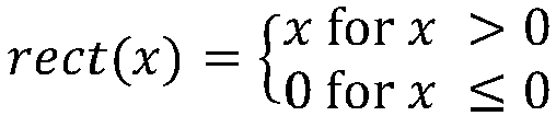
- In a data representation in which a data value is represented by a zero bit (indicating whether the data value is 0), a sign bit (indicating the whether the data value is positive or negative) and the magnitude (indicating the magnitude of the data value),
rectifier 2408 can be configured to return 0 whenever the sign bit indicates a negative number or if the zero bit is set, and return the magnitude otherwise. - When the control signal s1 is set to 3, functional unit is configured to add a bias value to the data stored in
accumulators convolver unit 806. -
Figure 25 depicts three scenarios of data values being loaded frominput channel 702a intoconvolutional engine 708 having m columns of convolver units, with scenario (a) illustratinginput channel 702a having m columns of data values, scenario (b) illustratinginput channel 702a having 3m-4 columns of data values, and scenario (c) illustratinginput channel 702a having m/2 columns of data values, in accordance with one embodiment of the invention. Scenario (a) was previously described inFigure 9B , but will be more fully discussed inFigures 26A-26B . Scenario (b) discusses an example in which the number of columns ofinput channel 702a is greater than the number of columns of the convolver array. Scenario (c) discusses an example in which the number of columns ofinput channel 702a is less than the number of columns of the convolver array. While a convolutional engine is more abstractly depicted, it should be understood that the architecture of a convolutional engine may be similar to earlier described examples, with a 2-D shift register and a convolver array. -
Figure 26A depicts the loading of a zero padding row,horizontal stripe 902a and a data padding row (corresponding to row n ofhorizontal stripe 902b) intoconvolutional engine 708. (If not already apparent, the bolded dashed rectangle denotes the portion ofinput channel 702a being loaded intoconvolutional engine 708.) More specifically, the zero padding row is first loaded into the 2-D shift register ofconvolutional engine 708, followed by row n ofhorizontal stripe 902a, followed by row n-1 ofhorizontal stripe 902a, ... followed byrow 1 ofhorizontal stripe 902a, and followed by the data padding row. As described above, each time a row of data storage elements stores row n of a horizontal stripe, the convolver units corresponding to that row of data storage elements are activated. Eachtime row 1 of a horizontal stripe is shifted out of a row of data storage elements, the convolver units corresponding to that row of data storage elements are de-activated. -
Figure 26B depicts the loading of one data padding row (corresponding to row 1 ofhorizontal stripe 902a),horizontal stripe 902b and a zero padding row intoconvolutional engine 708. More specifically, the data padding row is first loaded into the 2-D shift register ofconvolutional engine 708, followed by row n ofhorizontal stripe 902b, followed by row n-1 ofhorizontal stripe 902b, ... followed byrow 1 ofhorizontal stripe 902b, and followed by the zero padding row. - While
input channel 702a included two horizontal stripes to illustrate the concept of a single "horizontal cut line" through the input data (conceptually located at the boundary ofhorizontal stripes -
Figures 27A-27C illustrate a scenario in which "vertical cut lines" throughinput channel 702a are needed, and how to handle the vertical cut lines. Generally, a vertical cut line is needed whenever the number of columns of the input channel is greater than the number of columns of the convolver array. The present example discusses the scenario in which the number of columns of the input channel is equal to 3m-4, where m is the number of columns of the convolver array. Whenever the number of columns of the input channel is equal to two more than a multiple of m-2 (as is true in the present example), the convolver array is utilized in an efficient manner (no unused convolver units), but if this relationship does not hold, the concepts described below still apply, but the convolver array will be utilized in a less efficient manner (will have unused convolver units). Further, for the sake of clarity of illustration and explanation, horizontal cut lines, zero padding rows, data padding rows are not discussed in the example ofFigures 27A-27C . Nevertheless, it is expected that one of ordinary skill in the art will be able to combine concepts fromFigures 26A-26B and 27A-27B in order to handle scenarios in which there are both horizontal and vertical cut lines. - In
Figure 27A ,input channel 702a is divided intovertical stripes vertical stripe 906a from vertical stripe 906b, and a second vertical cut line separating vertical stripe 906b from 906c. In an efficient use of the convolutional engine, interior vertical stripes (such as 906b) contain m-2 columns, whereas exterior vertical stripes (such as 906a and 906c) contain m-1 columns.Figure 27A depicts m columns (including the m-1 columns ofvertical stripe 906a and one data padding column) being loaded intoconvolutional engine 708. The right most column of convolver units (which aligns with the data padding column) is non-active, as the output of these convolver units would have produced a convolution output treating the data padding column as an external column (which is not true in the current scenario). The remaining m-1 columns of the convolver units operate in a similar manner as the convolver units that have been previously described. -
Figure 27B depicts m columns (including the m-2 columns of vertical stripe 906b bordered on the right and left sides by a data padding column) being loaded intoconvolutional engine 708. The left most and right most columns of convolver units (which align with the data padding columns) are non-active, for reasons similar to those provided above. The remaining m-2 columns of the convolver units operate in a similar manner as the convolver units that have been previously described. -
Figure 27C depicts m columns (including one data padding column and the m-1 columns ofvertical stripe 906c) being loaded intoconvolutional engine 708. The left most column of convolver units (which aligns with the data padding column) is non-active, for reasons similar to those provided above. The remaining m-1 columns of the convolver units operate in a similar manner as the convolver units that have been previously described. -
Figure 28 describes the scenario in which the number of columns of theinput channel 702a is equal to m/2, in which m is the number of columns of the convolutional engine. The variable m is assumed to be an even number for the example ofFigure 28 , but need not be an even number in general. Whenever the number of columns of the input channel is equal to a divisor of m (as is true in the present example), the convolver array is utilized in an efficient manner (i.e., will have no unused convolver units), but if this relationship does not hold, the concepts described below still apply, but the convolver array will be utilized in a less efficient manner (i.e., will have unused convolver units). - The example of
Figure 28 illustrates the concept of a "vertical cut line" through theconvolutional engine 708, in which there is no transfer of data betweenregion 708a (which includes the first half of the "columns" of the convolutional engine) andregion 708b (which includes the second half of the "columns" of the convolutional engine). The term column, when used in the context of a convolutional engine, includes a column of the 2-D shift register and the corresponding column of convolutional units. Conceptually, one can imagine a vertical cut line that separatesregion 708a fromregion 708b.Region 708a essentially functions independently fromregion 708b, allowingregion 708a to be configured to perform a convolution with a first set of filters (e.g., filters 1 through 10), andregion 708b to be configured to perform the convolution with a second set of filters (e.g., filters 11-20). The number of filters (10 in each region) was chosen for clarity of explanation, and it is understood that there could have been a different number of filters in one or both of the two regions. The partitioning of the convolutional engine into independent regions (2 regions in this case, but could be more regions in other cases), allows for an increased throughput for the convolutional engine (in this case a doubling of the throughput). - As a concrete example, suppose that convolutional engine has 14 columns of convolver units. The weights of
filter 1 would be loaded in each of convolver units 1-7 of the first row of convolver units, and the weights offilter 11 would be loaded in each of convolver units 8-14 of the first row of convolver units. - To configure
convolutional engine 708 to operate with a "vertical cut line", convolver units in the right most column ofregion 708a have weights w 3 , w 6 and w 9 set to zero (regardless of what those weights might be from the filter kernels), and convolver units in the left most column ofregion 708b have weights w 1 , w 4 and w 7 set to zero (regardless of what those weights might be from the filter kernels). Such setting of weights results in the data flow shown in the inset ofFigure 28 , in which convolver units in the right most column ofregion 708a do not receive any data values from its "right neighbors", and the convolver units in the left most column ofregion 708b do not receive any data values from its "left neighbors". - When
input channel 702a is loaded intoconvolutional engine 708, it is loaded intoregion 708a row-by-row, and at the same time, it is loaded intoregion 708b row-by-row. If the propagation of data throughconvolutional engine 708 could conceptually be viewed as a ticker time traversing in the vertical direction, there would be one ticker tape traversing downregion 708a, and there would be a mirror image of that ticker tape traversing downregion 708b. - While
Figure 28 illustrated an example with one vertical cut line through the convolutional engine, it should be apparent how a convolutional engine could be modified to have multiple vertical cut lines. Further, for the sake of clarity of illustration and explanation, horizontal cut lines, zero padding rows, data padding rows are not discussed in the example ofFigure 28 . Nevertheless, it is expected that one of ordinary skill in the art will be able to combine concepts fromFigures 26A-26B and28 together to handle scenarios in which there are both horizontal and vertical cut lines. -
Figures 29A-29B illustrate another scheme for handling the scenario in which the number of columns of theinput channel 702a is equal to m/2, in which m is the number of columns ofconvolutional engine 708. The scheme involves combining the concept of a horizontal cut line through the input data (described inFigures 26A-26B ) and the concept of a vertical cut line through the convolver array (described inFigure 28 ). In theFigures 26A-26B , the two horizontal stripes were processed one after another (i.e., serially). However, in the example ofFigures 29A-29B , thehorizontal stripes 908a and 908b are processed in parallel, withhorizontal stripe 908a processed inregion 708a, and horizontal stripe 908b processed inregion 708b. The same filters are populated inregions Figure 28 . - Since there are several overlapping rectangles in
Figure 29A , the scheme is conceptually redrawn inFigure 29B , which more clearly shows the data loaded intoregion 708a andregion 708b. If not already apparent, it is noted thatrow 1 ofhorizontal stripe 908a is identical to the data padding row that precedes horizontal stripe 908b, and the data padding row that followshorizontal stripe 908a is identical to row n of horizontal stripe 908b. - Similar to the scheme of
Figures 28 , the scheme ofFigures 29A-29B also has the effect of doubling the throughput. At this point, since there are two possible schemes for handling the m/2 scenario, one might wonder which scheme is preferable. One consideration between the scheme ofFigure 28 and the scheme ofFigures 29A-29B is the number of filters versus the number of rows of the input channel. If there are many more filters than the number of rows of the input channel, then the scheme ofFigure 28 might be preferred, whereas if there are many more rows of the input channel than the number of filters, then the scheme ofFigures 29A-29B might be preferred. Intuitively, the former case would be analogous to a long skinny column of filters, in which it would be advantageous to cut the long skinny column of filters in half (place one half inregion 708a and the other half inregion 708b), whereas the latter case would be analogous to a long skinny column of input data, in which it would be advantageous to cut the long skinny column of input data in half and process the two halves of input data in parallel. - Other considerations for favoring one scheme over the another might also include the number of filters relative to the number of rows of convolver units. If the number of filters were less than the number of rows of convolver units, then the scheme of
Figure 29A-29B might be preferred, whereas if the number of filters were more than the number of rows of convolver units, then the scheme ofFigure 28 might be preferred. -
Figure 30 depictsconvolutional engine 708 as one component ofsystem 3000, in accordance with one embodiment of the invention.System 3000 may include memory 3002, shift andformat module 3004,convolutional engine 708 andcontroller 3006. - Memory 3002 may be implemented using static random-access memory (SRAM), and may store
input data 702, and the output of the convolutional engine 708 (e.g., convolution output, max pool output, rectified output, etc.). - Shift and
format module 3004 is an interface between memory 3002 andconvolutional engine 708 and is configured to shift and format the data. For instance, in the example ofFigure 29A , providing horizontal stripe 908b toregion 708b of the convolutional engine would be one task performed by shift andformat module 3004. Achieving a stride of ½ (or a stride less than one) could also involve shift andformat module 3004, in which the above-described interpolation could be performed by the shift andformat module 3004. - In the embodiment of
Figure 30 ,convolutional engine 708 contains a more typical number of data storage elements and convolver units.Figure 30 depicts a convolutional engine with a 64 by 256 array ofconvolver units 806 and a 66 by 256 array of data storage elements configured as a 2-D shift register. Similar to the previously-described embodiments, the first row of convolver units logically corresponds with the second row of data storage elements, and the last row of convolver units logically corresponds with the second to last row of data storage elements. -
Controller 3006 may be responsible for performing many of the above-described control operations. For example,controller 3006 may provide the control signals that set convolver units to be active and non-active (and hence, the above-described controller 2202 may be part of controller 3006)Controller 3006 may be responsible for providing control signal s1 (described inFigures 21 and24 ) for controlling the output ofoutput selectors Controller 3006 may be responsible for providing control signal s2 (described inFigure 24 ) for controlling whether a functional unit is programmed to output a convolution output or a max pool output.Controller 3006 may logically partition an input channel into horizontal stripes, vertical stripes (more appropriately called chunks when there are vertical and horizontal cut lines) based on the dimensions of the input channel relative to the dimensions of the convolver array.Controller 3006 may control shift andformat module 3004 to perform the necessary shift and format operations.Controller 3006 may determine which weights are to be loaded to which convolutional units.Controller 3006 may determine whether to override filter weights with zero values in order to logically partition the convolutional engine into multiple independent regions (as depicted inFigures 28 ,29A and29B ).Controller 3006 may also contain the logic that determines, for the loading of a horizontal stripe into the convolutional engine, whether a horizontal stripe is to be preceded by a zero padding row or a data padding row, whether a horizontal stripe is to be followed by a zero padding row or a data padding row. These are merely some examples of the functions that may be performed bycontroller 3006. -
Figure 31 depicts a block diagram ofweight decompressor 3100 for decompressing filter weights before the weights are provided to the convolver units, in accordance with one embodiment of the invention.Weight decompressor 3100 may utilizedictionary 3102 to decompress weights. In one embodiment, compressed weights are keys to a look-up table (an embodiment of the dictionary), and the records corresponding to the keys in the look-up table are the decompressed weights. The 256 convolver units may be logically and/or physically grouped into 16 groups, each group including 16 convolver units. The decompressed weights may be provided to each of the 16 groups of convolver units. - Thus, an efficient convolutional engine has been described. In one embodiment, the convolutional engine includes a two-dimensional shift register having a three by four array of data storage elements:

- data storage element d 1,1 stores data value x 1,1,
- data storage element d 1,2 stores data value x 1,2,
- data storage element d 1,3 stores data value x 1,3,
- data storage element d 1,4 stores data value x 1,4,
- data storage element d 2,1 stores data value x 2,1,
- data storage element d 2,2 stores data value x 2,2,
- data storage element d 2,3 stores data value x 2,3,
- data storage element d 2,4 stores data value x 2,4,
- data storage element d 3,1 stores data value x 3,1,
- data storage element d 3,2 stores data value x 3,2,
- data storage element d 3,3 stores data value x 3,3, and
- data storage element d 3,4 stores data value x 3,4.
-
multiplier 
-
multiplier 
-
multiplier 
-
multiplier 
-
multiplier 
-
multiplier 
-
multiplier 
-
multiplier 
-
multiplier 
-
multiplier 
-
multiplier 
-
multiplier 
-
multiplier 
-
multiplier 
-
multiplier 
-
multiplier 
-
multiplier 
-
multiplier 
- In various embodiments, the first convolver unit may be configured to generate a sum of terms, the terms including at least the product w 1 x 1,1, the product w 2 x 1,2, the product w 3 x 1,3, the product w 4 x 2,1, the product w 5 x 2,2, the product w 6 x 2,3, the product w 7 x 3,1, the product w 8 x 3,2, the product w 9 x 3,3 and b 1, wherein b 1 is a bias value. Further, the second convolver unit may be configured to compute a sum of terms, the terms including at least the product w 1 x 1,2, the product w 2 x 1,3, the product w 3 x 1,4,the product w 4 x 2,2, the product w 5 x 2,3, the product w 6 x 2,4, the product w 7 x 3,2, the product w 8 x 3,3, the product w 9 x 3,4 and b 1, wherein b 1 is a bias value.
- In some instances:
- data storage element d 1,1 is electrically coupled to data storage element d 2,1,
- data storage element d 2,1 is electrically coupled to data storage element d 3,1,
- data storage element d 1,2 is electrically coupled to data storage element d 2,2,
- data storage element d 2,2 is electrically coupled to data storage element d 3,2,
- data storage element d 1,3 is electrically coupled to data storage element d 2,3,
- data storage element d 2,3 is electrically coupled to data storage element d 3,3,
- data storage element d 1,4 is electrically coupled to data storage element d 2,4, and
- data storage element d 2,4 is electrically coupled to data storage element d 3,4.
- Further embodiments of the invention provide an apparatus, that includes a two-dimensional shift register having a four by four array of data storage elements:

- data storage element d 1,1 stores data value x 1,1,
- data storage element d 1,2 stores data value x 1,2,
- data storage element d 1,3 stores data value x 1,3,
- data storage element d 1,4 stores data value x 1,4,
- data storage element d 2,1 stores data value x 2,1,
- data storage element d 2,2 stores data value x 2,2,
- data storage element d 2,3 stores data value x 2,3,
- data storage element d 2,4 stores data value x 2,4,
- data storage element d 3,1 stores data value x 3,1,
- data storage element d 3,2 stores data value x 3,2,
- data storage element d 3,3 stores data value x 3,3,
- data storage element d 3,4 stores data value x 3,4,
- data storage element d 4,1 stores data value x 4,1,
- data storage element d 4,2 stores data value x 4,2,
- data storage element d 4,3 stores data value x 4,3, and
- data storage element d 4,4 stores data value x 4,4.
-
multiplier 
-
multiplier 
-
multiplier 
-
multiplier 
-
multiplier 
-
multiplier 
-
multiplier 
-
multiplier 
-
multiplier 
-
multiplier 
-
multiplier 
-
multiplier 
-
multiplier 
-
multiplier 
-
multiplier 
-
multiplier 
-
multiplier 
-
multiplier 
-
multiplier 
-
multiplier 
-
multiplier 
-
multiplier 
-
multiplier 
-
multiplier 
-
multiplier 
-
multiplier 
-
multiplier 
-
multiplier 
-
multiplier 
-
multiplier 
-
multiplier 
-
multiplier 
-
multiplier 
-
multiplier 
-
multiplier 
-
multiplier 
- In some embodiments, the first convolver unit of this apparatus may be configured to generate a sum of terms, the terms including at least the product w 1 x 1,1, the product w 2 x 1,2, the product w 3 x 1,3, the product w 4 x 2,1, the product w 5 x 2,2, the product w 6 x 2,3, the product w 7 x 3,1, the product w 8 x 3,2, the product w 9 x 3,3 and b 1, wherein b 1 is a bias value. Also, the second convolver unit may be configured to compute a sum of terms, the terms including at least the product w 1 x 1,2, the product w 2 x 1,3, the product w 3 x 1,4, the product w 4 x 2,2, the product w 5 x 2,3, the product w 6 x 2,4, the product w 7 x 3,2, the product w 8 x 3,3, the product w 9 x 3,4 and b 1, wherein b 1 is a bias value.
- In still further embodiments, the third convolver unit may be configured to generate a sum of terms, the terms including at least the product w 10 x 2,1, the product w 11 x 2,2, the product w 12 x 2,3, the product w 13 x 3,1, the product w 14 x 3,2, the product w 15 x 3,3, the product w 16 x 4,1 , the product w 17 x 4,2, the product w 18 x 4,3 and b 2, wherein b 2 is a bias value. Also, the fourth convolver unit may be configured to compute a sum of terms, the terms including at least the product w 10 x 2,2, the product w11 x 2,3, the product w 12 x 2,4, the product w 13 x 3,2, the product w 14 x 3,3, the product w 15 x 3,4, the product w 16 x 4,2, the product w 17 x 4,3, the product w 18 x 4,4 and b 2, wherein b 2 is a bias value.
- In various embodiments:
- data storage element d 1,1 is electrically coupled to data storage element d 2,1,
- data storage element d 2,1 is electrically coupled to data storage element d 3,1,
- data storage element d 3,1 is electrically coupled to data storage element d 4,1,
- data storage element d 1,2 is electrically coupled to data storage element d 2,2,
- data storage element d 2,2 is electrically coupled to data storage element d 3,2,
- data storage element d 3,2 is electrically coupled to data storage element d 4,2,
- data storage element d 1,3 is electrically coupled to data storage element d 2,3,
- data storage element d 2,3 is electrically coupled to data storage element d 3,3,
- data storage element d 3,3 is electrically coupled to data storage element d 4,3,
- data storage element d 1,4 is electrically coupled to data storage element d 2,4,
- data storage element d 2,4 is electrically coupled to data storage element d 3,4, and
- data storage element d 3,4 is electrically coupled to data storage element d 4,4.
- Still another embodiment of the invention provides an apparatus that includes a two-dimensional synchronous shift register comprising a p by q array of data storage elements:

- (i) a first input of CUi,j is electrically coupled to data storage element d i,j-1,
- (ii) a second input of CUi,j is electrically coupled to data storage element di+1,j-1,
- (iii) a third input of CUi,j is electrically coupled to data storage element d i+2,j-1,
- (iv) a fourth input of CUi,j is electrically coupled to data storage element di,j,
- (v) a fifth input of CUi,j is electrically coupled to data storage element d i+1,j ,
- (vi) a sixth input of CUi,j is electrically coupled to data storage element d i+2,j ,
- (vii) a seventh input of CUi,j is electrically coupled to data storage element d i,j+1,
- (viii) an eighth input of CUi,j is electrically coupled to data storage element d i+1,j+1, and
- (ix) a ninth input of CUi,j is electrically coupled to data storage element d i+2,j+1.
- In some embodiments, for convolver units CU i,1, 1 ≤ i ≤ p - 2,
- (i) at least one of a first input of CU i,1 or a weight associated with the first input is set to logical zero,
- (ii) at least one of a second input of CU i,1 or a weight associated with the second input is set to logical zero,
- (iii) at least one of a third input of CU i,1 or a weight associated with the third input is set to logical zero,
- (iv) a fourth input of CU i,1 is electrically coupled to data storage element d i,1,
- (v) a fifth input of CU i,1 is electrically coupled to data storage element d i+1,1,
- (vi) a sixth input of CU i,1 is electrically coupled to data storage element d i+2,1,
- (vii) a seventh input of CU i,1 is electrically coupled to data storage element d i,2,
- (viii) an eighth input of CU i,1 is electrically coupled to data storage element d i+1,2, and
- (ix) a ninth input of CU i,1 is electrically coupled to data storage element d i+2,2.
- Further, in some embodiments, for convolver units CUi,q, 1 ≤ i ≤ p - 2,
- (i) a first input of CUi,q is electrically coupled to data storage element d i,q-1,
- (ii) a second input of CUi,q is electrically coupled to data storage element d i+1,q-1,
- (iii) a third input of CUi,q is electrically coupled to data storage element d i+2,q-1,
- (iv) a fourth input of CUi,q is electrically coupled to data storage element di,q,
- (v) a fifth input of CUi,q is electrically coupled to data storage element d i+1, q,
- (vi) a sixth input of CUi,q is electrically coupled to data storage element d i+2,q ,
- (vii) at least a seventh input of CUi,q or a weight associated with the seventh input is set to logical zero,
- (viii) at least an eighth input of CUi,q or a weight associated with the eight input is set to logical zero, and
- (ix) at least a ninth input of CUi,q or a weight associated with the ninth input is set to logical zero.
- It is to be understood that the above-description is intended to be illustrative, and not restrictive. Many other embodiments will be apparent to those of skill in the art upon reviewing the above description. The scope of the invention should, therefore, be determined with reference to the appended claims, along with the full scope of equivalents to which such claims are entitled.
- The present application discloses subject matter in accordance with the following numbered clauses:
- Clause A1. An apparatus, comprising:
- a two-dimensional shift register comprising a three by four array of data storage elements:

- wherein, at a first moment in time,
- data storage element d 1,1 stores data value x 1,1,
- data storage element d 1,2 stores data value x 1,2,
- data storage element d 1,3 stores data value x 1,3,
- data storage element d 1,4 stores data value x 1,4,
- data storage element d 2,1 stores data value x 2,1,
- data storage element d 2,2 stores data value x 2,2,
- data storage element d 2,3 stores data value x 2,3,
- data storage element d 2,4 stores data value x 2,4,
- data storage element d 3,1 stores data value x 3,1,
- data storage element d 3,2 stores data value x 3,2,
- data storage element d 3,3 stores data value x 3,3, and
- data storage element d 3,4 stores data value x 3,4;
- a first convolver unit comprising a first plurality of multipliers,


-
multiplier 
-
multiplier 
-
multiplier 
-
multiplier 
-
multiplier 
-
multiplier 
-
multiplier 
-
multiplier 
-
multiplier 
-
- a second convolver unit comprising a second plurality of multipliers,


-
multiplier 
-
multiplier 
-
multiplier 
-
multiplier 
-
multiplier 
-
multiplier 
-
multiplier 
-
multiplier 
-
multiplier 
-
- a two-dimensional shift register comprising a three by four array of data storage elements:
- Clause A2. The apparatus of clause A1, wherein the first convolver unit is configured to generate a sum of terms, the terms including at least the product w 1 x 1,1, the product w 2 x 1,2, the product w 3 x 1,3, the product w 4 x 2,1, the product w 5 x 2,2, the product w 6 x 2,3, the product w 7 x 3,1, the product w 8 x 3,2, the product w 9 x 3,3 and b 1, wherein b 1 is a bias value.
- Clause A3. The apparatus of clause A1, wherein the second convolver unit is configured to generate a sum of terms, the terms including at least the product w1 x 1,2, the product w 2 x 1,3, the product w 3 x 1,4, the product w 4 x 2,2, the product w 5 x 2,3, the product w 6 x 2,4, the product w 7 x 3,2, the product w 8 x 3,3, the product w 9 x 3,4 and b 1, wherein b 1 is a bias value.
- Clause A4. The apparatus of clause A1, wherein:
- data storage element d 1,1 is electrically coupled to data storage element d 2,1,
- data storage element d 2,1 is electrically coupled to data storage element d 3,1,
- data storage element d 1,2 is electrically coupled to data storage element d 2,2,
- data storage element d 2,2 is electrically coupled to data storage element d 3,2,
- data storage element d 1,3 is electrically coupled to data storage element d 2,3,
- data storage element d 2,3 is electrically coupled to data storage element d 3,3,
- data storage element d 1,4 is electrically coupled to data storage element d 2,4, and
- data storage element d 2,4 is electrically coupled to data storage element d 3,4.
- Clause A5. An apparatus, comprising:
- a two-dimensional shift register comprising a four by four array of data storage elements,

- wherein, at a first moment in time,
- data storage element d 1,1 stores data value x 1,1,
- data storage element d 1,2 stores data value x 1,2,
- data storage element d 1,3 stores data value x 1,3,
- data storage element d 1,4 stores data value x 1,4,
- data storage element d 2,1 stores data value x 2,1,
- data storage element d 2,2 stores data value x 2,2,
- data storage element d 2,3 stores data value x 2,3,
- data storage element d 2,4 stores data value x 2,4,
- data storage element d 3,1 stores data value x 3,1,
- data storage element d 3,2 stores data value x 3,2,
- data storage element d 3,3 stores data value x 3,3,
- data storage element d 3,4 stores data value x 3,4,
- data storage element d 4,1 stores data value x 4,1,
- data storage element d 4,2 stores data value x 4,2,
- data storage element d 4,3 stores data value x 4,3, and
- data storage element d 4,4 stores data value x 4,4;
- a first convolver unit comprising a first plurality of multipliers,


-
multiplier 
-
multiplier 
-
multiplier 
-
multiplier 
-
multiplier 
-
multiplier 
-
multiplier 
-
multiplier 
-
multiplier 
-
- a second convolver unit comprising a second plurality of multipliers,


-
multiplier 
-
multiplier 
-
multiplier 
-
multiplier 
-
multiplier 
-
multiplier 
-
multiplier 
-
multiplier 
-
multiplier 
-
- a third convolver unit comprising a third plurality of multipliers,


-
multiplier 
-
multiplier 
-
multiplier 
-
multiplier 
-
multiplier 
-
multiplier 
-
multiplier 
-
multiplier 
-
multiplier 
-
- a fourth convolver unit comprising a fourth plurality of multipliers,


-
multiplier 
-
multiplier 
-
multiplier 
-
multiplier 
-
multiplier 
-
multiplier 
-
multiplier 
-
multiplier 
-
multiplier 
-
- a two-dimensional shift register comprising a four by four array of data storage elements,
- Clause A6. The apparatus of clause A5, wherein the first convolver unit is configured to generate a sum of terms, the terms including at least the product w 1 x 1,1, the product w 2 x 1,2, the product w 3 x 1,3, the product w 4 x 2,1, the product w 3 x 2,2, the product w 6 x 2,3, the product w 7 x 3,1, the product w 8 x 3,2, the product w 9 x 3,3 and b 1, wherein b 1 is a bias value.
- Clause A7. The apparatus of clause A5, wherein the second convolver unit is configured to generate a sum of terms, the terms including at least the product w 1 x 1,2, the product w 2 x 1,3, the product w 3 x 1,4, the product w 4 x 2,2, the product w 5 x 2,3, the product w 6 x 2,4, the product w 7 x 3,2, the product w 8 x 3,3, the product w 9 x 3,4 and b 1, wherein b 1 is a bias value.
- Clause A8. The apparatus of clause A5, wherein the third convolver unit is configured to generate a sum of terms, the terms including at least the product w 10 x 2,1, the product w 11 x 2,2, the product w 12 x 2,3, the product w 13 x 3,1, the product w 14 x 3,2, the product w 15 x 3,3, the product w 16 x 4,1 , the product w 17 x 4,2, the product w 18 x 4,3 and b 2, wherein b2 is a bias value.
- Clause A9. The apparatus of clause A5, wherein the fourth convolver unit is configured to generate a sum of terms, the terms including at least the product w 10 x 2,2, the product w 11 x 2,3, the product w 12 x 2,4, the product w 13 x 3,2, the product w 14 x 3,3, the product w 15 x 3,4, the product w 16 x 4,2, the product w 17 x 4,3, the product w 18 x 4,4 and b 2, wherein b 2 is a bias value.
- Clause A10. The apparatus of clause A5, wherein:
- data storage element d 1,1 is electrically coupled to data storage element d 2,1,
- data storage element d 2,1 is electrically coupled to data storage element d 3,1,
- data storage element d 3,1 is electrically coupled to data storage element d 4,1,
- data storage element d 1,2 is electrically coupled to data storage element d 2,2,
- data storage element d 2,2 is electrically coupled to data storage element d 3,2,
- data storage element d 3,2 is electrically coupled to data storage element d 4,2,
- data storage element d 1,3 is electrically coupled to data storage element d 2,3,
- data storage element d 2,3 is electrically coupled to data storage element d 3,3,
- data storage element d 3,3 is electrically coupled to data storage element d 4,3,
- data storage element d 1,4 is electrically coupled to data storage element d 2,4,
- data storage element d 2,4 is electrically coupled to data storage element d 3,4, and
- data storage element d 3,4 is electrically coupled to data storage element d 4,4.
- Clause A11. An apparatus, comprising:
- a two-dimensional synchronous shift register comprising a p by q array of data storage elements:
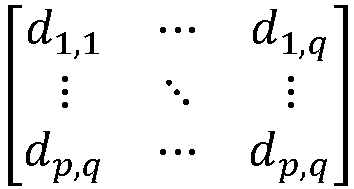
- a convolver array configured to process the data values stored in the two-dimensional synchronous shift register, wherein the convolver array comprises a p - 2 by q array of convolver units, wherein for convolver units CUi,j, 1 ≤ i ≤ p - 2 and 2 ≤ j ≤ q - 1:
- (i) a first input of CUi,j is electrically coupled to data storage element d i,j-1,
- (ii) a second input of CUi,j is electrically coupled to data storage element d i+1,j-1,
- (iii) a third input of CUi,j is electrically coupled to data storage element d i+2,j-1,
- (iv) a fourth input of CUi,j is electrically coupled to data storage element di,j,
- (v) a fifth input of CUi,j is electrically coupled to data storage element d i+1,j ,
- (vi) a sixth input of CUi,j is electrically coupled to data storage element d i+2,j ,
- (vii) a seventh input of CUi,j is electrically coupled to data storage element d i,j+1,
- (viii) an eighth input of CUi,j is electrically coupled to data storage element d i+1,j+1, and
- (ix) a ninth input of CUi,j is electrically coupled to data storage element d i+2,j+1.
- a two-dimensional synchronous shift register comprising a p by q array of data storage elements:
- Clause A12. The apparatus of clause A11, wherein for convolver units CU i,1, 1 ≤ i ≤ p - 2,
- (i) at least one of a first input of CU i,1 or a weight associated with the first input is set to logical zero,
- (ii) at least one of a second input of CU i,1 or a weight associated with the second input is set to logical zero,
- (iii) at least one of a third input of CU i,1 or a weight associated with the third input is set to logical zero,
- (iv) a fourth input of CU i,1 is electrically coupled to data storage element d i,1,
- (v) a fifth input of CU i,1 is electrically coupled to data storage element d i+1,1,
- (vi) a sixth input of CU i,1 is electrically coupled to data storage element d i+2,1,
- (vii) a seventh input of CU i,1 is electrically coupled to data storage element d i,2,
- (viii) an eighth input of CU i,1 is electrically coupled to data storage element d i+1,2, and
- (ix) a ninth input of CU i,1 is electrically coupled to data storage element d i+2,2.
- Clause A13. The apparatus of clause A11, wherein for convolver units CUi,q , 1 ≤ i ≤ p - 2,
- (i) a first input of CUi,q is electrically coupled to data storage element d i,q-1,
- (ii) a second input of CUi,q is electrically coupled to data storage element d i+1,q-1,
- (iii) a third input of CUi,q is electrically coupled to data storage element d i+2,q-1,
- (iv) a fourth input of CUi,q is electrically coupled to data storage element di,q,
- (v) a fifth input of CUi,q is electrically coupled to data storage element d i+1,q ,
- (vi) a sixth input of CUi,q is electrically coupled to data storage element d i+2,q ,
- (vii) at least a seventh input of CUi,q or a weight associated with the seventh input is set to logical zero,
- (viii) at least an eighth input of CUi,q or a weight associated with the eight input is set to logical zero, and
- (ix) at least a ninth input of CUi,q or a weight associated with the ninth input is set to logical zero.
Claims (15)
- A method for processing input data (702) with a convolutional engine (708) comprising (i) a two-dimensional synchronous shift register and (ii) convolver units (806) including a first convolver unit and a second convolver unit,wherein the two-dimensional synchronous shift register comprises a three-by-four array of data storage elements:
 wherein:data storage element d 1,1 is electrically coupled to data storage element d 2,1,data storage element d 2,1 is electrically coupled to data storage element d 3,1,data storage element d 1,2 is electrically coupled to data storage element d 2,2,data storage element d 2,2 is electrically coupled to data storage element d 3,2,data storage element d 1,3 is electrically coupled to data storage element d 2,3,data storage element d 2,3 is electrically coupled to data storage element d 3,3,data storage element d 1,4 is electrically coupled to data storage element d 2,4, anddata storage element d 2,4 is electrically coupled to data storage element d 3,4,wherein the first convolver unit comprises a first plurality of multipliers,
 wherein:multiplier
 multiplier
 multiplier
 multiplier
 multiplier
 multiplier
 multiplier
 multiplier
 multiplier
 wherein the second convolver unit comprises a second plurality of multipliers,

 multiplier
 multiplier
 multiplier
 multiplier
 multiplier
 multiplier
 multiplier
 multiplier
 processing, by the convolutional engine, the first vertical stripe (906a) by computing a first plurality of dot products based on the first vertical stripe (906a) and providing the first plurality of dot products to accumulators (1102a, 1104a, 1106a, 1108a, 1110a, 1112a, 1114a, 1116a, 1102b, 1104b, 1106b, 1108b) of the convolver units (806),wherein computing the first plurality of dot products comprises:storing data value
 storing data value
 storing data value
 storing data value
 storing data value
 storing data value
 storing data value
 storing data value
 storing data value
 storing data value
 storing data value
 storing data value

 multiplying by multiplier


 multiplying by multiplier


 multiplying by multiplier


 multiplying by multiplier


 multiplying by multiplier


 multiplying by multiplier


 multiplying by multiplier


 multiplying by multiplier


 multiplying by multiplier


 multiplying by multiplier


 multiplying by multiplier


 multiplying by multiplier


 multiplying by multiplier


 multiplying by multiplier


 multiplying by multiplier


 multiplying by multiplier


 multiplying by multiplier


 multiplying by multiplier


 generating, by the first convolver unit, a first sum of terms y 1 including at least the product


 generating, by the second convolver unit, a second sum of terms y 2 including at least the product


 wherein the first plurality of dot products includes the first sum of terms y 1 and the second sum of terms y 2;processing by the convolutional engine (708) the third vertical stripe by computing a second plurality of dot products based on the third vertical stripe and summing the second plurality of dot products and the first plurality of dot products with the accumulators (1102a, 1104a, 1106a, 1108a, 1110a, 1112a, 1114a, 1116a, 1102b, 1104b, 1106b, 1108b) of the convolver units (806),wherein computing the second plurality of dot products comprises:storing data value
 storing data value
 storing data value
 storing data value
 storing data value
 storing data value
 storing data value
 storing data value
 storing data value
 storing data value
 storing data value
 storing data value

 multiplying by multiplier


 multiplying by multiplier


 multiplying by multiplier


 multiplying by multiplier


 multiplying by multiplier


 multiplying by multiplier


 multiplying by multiplier


 multiplying by multiplier


 multiplying by multiplier


 multiplying by multiplier


 multiplying by multiplier


 multiplying by multiplier


 multiplying by multiplier


 multiplying by multiplier


 multiplying by multiplier


 multiplying by multiplier


 multiplying by multiplier


 multiplying by multiplier


 generating, by the first convolver unit, a third sum of terms y 3 including at least the product


 generating, by the second convolver unit, a fourth sum of terms y 4 including at least the product


 wherein the second plurality of dot products includes the third sum of terms y 3 and the fourth sum of terms y 4,wherein summing the second plurality of dot products and the first plurality of dot products comprises summing the first sum of terms y 1 with the third sum of terms y 3 and summing the second sum of terms y 2 with the fourth sum of terms y 4;processing by the convolutional engine (708) the second vertical stripe (906b) by computing a third plurality of dot products based on the second vertical stripe (906b) and providing the third plurality of dot products to the accumulators (1102a, 1104a, 1106a, 1108a, 1110a, 1112a, 1114a, 1116a, 1102b, 1104b, 1106b, 1108b) of the convolver units (806),wherein computing the third plurality of dot products comprises:storing data value
 storing data value
 storing data value
 storing data value
 storing data value
 storing data value
 storing data value
 storing data value
 storing data value
 storing data value
 storing data value
 storing data value

 multiplying by multiplier


 multiplying by multiplier


 multiplying by multiplier


 multiplying by multiplier


 multiplying by multiplier


 multiplying by multiplier


 multiplying by multiplier


 multiplying by multiplier


 multiplying by multiplier


 multiplying by multiplier


 multiplying by multiplier


 multiplying by multiplier


 multiplying by multiplier


 multiplying by multiplier


 multiplying by multiplier


 multiplying by multiplier


 multiplying by multiplier


 multiplying by multiplier


 generating, by the first convolver unit, a fifth sum of terms y 5 including at least the product


 generating, by the second convolver unit, a sixth sum of terms y 6 including at least the product


 wherein the third plurality of dot products includes the fifth sum of terms y 5 and the sixth sum of terms y 6; andprocessing by the convolutional engine (708) the fourth vertical stripe by computing a fourth plurality of dot products based on the fourth vertical stripe and summing the third plurality of dot products and the fourth plurality of dot products with the accumulators (1102a, 1104a, 1106a, 1108a, 1110a, 1112a, 1114a, 1116a, 1102b, 1104b, 1106b, 1108b) of the convolver units (806),wherein computing the fourth plurality of dot products comprises:storing data value
 storing data value
 storing data value
 storing data value
 storing data value
 storing data value
 storing data value
 storing data value
 storing data value
 storing data value
 storing data value
 storing data value

 multiplying by multiplier


 multiplying by multiplier


 multiplying by multiplier


 multiplying by multiplier


 multiplying by multiplier


 multiplying by multiplier


 multiplying by multiplier


 multiplying by multiplier


 multiplying by multiplier


 multiplying by multiplier


 multiplying by multiplier


 multiplying by multiplier


 multiplying by multiplier


 multiplying by multiplier


 multiplying by multiplier


 multiplying by multiplier


 multiplying by multiplier


 multiplying by multiplier


 generating, by the first convolver unit, a seventh sum of terms y 7 including at least the product


 generating, by the second convolver unit, an eighth sum of terms y 8 including at least the product


 wherein the fourth plurality of dot products includes the seventh sum of terms y 7 and the eighth sum of terms y 8, andwherein summing the third plurality of dot products and the fourth plurality of dot products comprises summing the fifth sum of terms y 5 with the seventh sum of terms y 7 and summing the sixth sum of terms y 6 with the eighth sum of terms y 8.
 - The method of claim 1, wherein a total number of columns of the first vertical stripe (906a) equals one less than a total number of columns of the convolver units (806).
- The method of claim 1, wherein a total number of columns of the third vertical stripe equals one less than the total number of columns of the convolver units (806).
- The method of claim 1, further comprising loading the first vertical stripe (906a) into the convolutional engine (708) with a data padding column, wherein computing the first plurality of dot products is based on the first vertical stripe (906a) and the data padding column.
- The method of claim 4, wherein the data padding column is identical to a left-most column of the second vertical stripe (906b).
- The method of claim 1, wherein during the processing of the first vertical stripe (906a), a right-most column of the convolver units (806) of the convolution engine (708) is non-active.
- The method of claim 1, further comprising loading the third vertical stripe into the convolutional engine (708) with a data padding column, wherein computing the second plurality of dot products is based on the third vertical stripe and the data padding column.
- The method of claim 7, wherein the data padding column is identical to a left-most column of the fourth vertical stripe.
- The method of claim 1, wherein during the processing of the third vertical stripe, a right-most column of the convolver units (806) of the convolution engine (708) is non-active.
- The method of claim 1, further comprising loading the second vertical stripe (906b) into the convolutional engine (708) with a data padding column, wherein computing the third plurality of dot products is based on the second vertical stripe (906b) and the data padding column.
- The method of claim 10, wherein the data padding column is identical to a last column of the first vertical stripe (906a).
- The method of claim 1, wherein during the processing of the second vertical stripe (906b), a left-most column of the convolver units (806) of the convolution engine (708) is non-active.
- The method of claim 1, further comprising loading the fourth vertical stripe into the convolutional engine (708) with a data padding column, wherein computing the fourth plurality of dot products is based on the fourth vertical stripe and the data padding column.
- The method of claim 13, wherein the data padding column is identical to a last column of the third vertical stripe.
- The method of claim 1, wherein during the processing of the fourth vertical stripe, a left-most column of the convolver units (806) of the convolution engine (708) is non-active.
Applications Claiming Priority (5)
| Application Number | Priority Date | Filing Date | Title |
|---|---|---|---|
| US201862642578P | 2018-03-13 | 2018-03-13 | |
| US201862694290P | 2018-07-05 | 2018-07-05 | |
| PCT/US2019/017787 WO2019177735A1 (en) | 2018-03-13 | 2019-02-13 | Efficient convolutional engine |
| EP19708715.8A EP3766020B1 (en) | 2018-03-13 | 2019-02-13 | Efficient convolutional engine |
| EP23166763.5A EP4220488B1 (en) | 2018-03-13 | 2019-02-13 | Methods for processing horizontal stripes of data in an efficient convolutional engine |
Related Parent Applications (3)
| Application Number | Title | Priority Date | Filing Date |
|---|---|---|---|
| EP19708715.8A Division EP3766020B1 (en) | 2018-03-13 | 2019-02-13 | Efficient convolutional engine |
| EP23166763.5A Division EP4220488B1 (en) | 2018-03-13 | 2019-02-13 | Methods for processing horizontal stripes of data in an efficient convolutional engine |
| EP23166763.5A Division-Into EP4220488B1 (en) | 2018-03-13 | 2019-02-13 | Methods for processing horizontal stripes of data in an efficient convolutional engine |
Publications (2)
| Publication Number | Publication Date |
|---|---|
| EP4583000A2 true EP4583000A2 (en) | 2025-07-09 |
| EP4583000A3 EP4583000A3 (en) | 2025-08-20 |
Family
ID=65635810
Family Applications (4)
| Application Number | Title | Priority Date | Filing Date |
|---|---|---|---|
| EP23166763.5A Active EP4220488B1 (en) | 2018-03-13 | 2019-02-13 | Methods for processing horizontal stripes of data in an efficient convolutional engine |
| EP19708715.8A Active EP3766020B1 (en) | 2018-03-13 | 2019-02-13 | Efficient convolutional engine |
| EP25177710.8A Pending EP4583001A3 (en) | 2018-03-13 | 2019-02-13 | Methods for processing horizontal stripes of data in an efficient convolutional engine |
| EP25177620.9A Pending EP4583000A3 (en) | 2018-03-13 | 2019-02-13 | Methods for processing horizontal stripes of data in an efficient convolutional engine |
Family Applications Before (3)
| Application Number | Title | Priority Date | Filing Date |
|---|---|---|---|
| EP23166763.5A Active EP4220488B1 (en) | 2018-03-13 | 2019-02-13 | Methods for processing horizontal stripes of data in an efficient convolutional engine |
| EP19708715.8A Active EP3766020B1 (en) | 2018-03-13 | 2019-02-13 | Efficient convolutional engine |
| EP25177710.8A Pending EP4583001A3 (en) | 2018-03-13 | 2019-02-13 | Methods for processing horizontal stripes of data in an efficient convolutional engine |
Country Status (7)
| Country | Link |
|---|---|
| US (6) | US11468302B2 (en) |
| EP (4) | EP4220488B1 (en) |
| JP (2) | JP7171883B2 (en) |
| KR (1) | KR102516039B1 (en) |
| CN (1) | CN112236783B (en) |
| IL (3) | IL301126A (en) |
| WO (1) | WO2019177735A1 (en) |
Families Citing this family (8)
| Publication number | Priority date | Publication date | Assignee | Title |
|---|---|---|---|---|
| US11514136B2 (en) * | 2019-05-17 | 2022-11-29 | Aspiring Sky Co. Limited | Circuit for neural network convolutional calculation of variable feature and kernel sizes |
| US12254405B2 (en) * | 2021-03-12 | 2025-03-18 | Qualcomm Incorporated | Processing data in pixel-to-pixel neural networks |
| US11782310B2 (en) * | 2021-12-07 | 2023-10-10 | 3M Innovative Properties Company | Backlighting for display systems |
| US12456035B2 (en) * | 2021-12-08 | 2025-10-28 | Black Sesame Technologies Inc. | Neural networks graph partitioning system and method for the same |
| CN114371829B (en) * | 2022-01-05 | 2024-07-26 | 华中科技大学 | Data processing method in polynomial multiplier, polynomial multiplier and processor |
| JP7784945B2 (en) * | 2022-04-21 | 2025-12-12 | 株式会社日立製作所 | Information processing device, information processing method, information processing program, software creation device, software creation method, and software creation program |
| US11762946B1 (en) * | 2022-09-23 | 2023-09-19 | Recogni Inc. | Systems for using shifter circuit and 3×3 convolver units to emulate functionality of larger sized convolver units |
| CN120874928B (en) * | 2025-09-26 | 2025-12-16 | 中国人民解放军军事科学院国防科技创新研究院 | Design method and use method of variable precision calculation unit applied to quantized neural network convolution layer |
Family Cites Families (32)
| Publication number | Priority date | Publication date | Assignee | Title |
|---|---|---|---|---|
| US4347580A (en) * | 1980-07-21 | 1982-08-31 | The United States Of America As Represented By The Secretary Of The Navy | Array convolver/correlator |
| US5014235A (en) * | 1987-12-15 | 1991-05-07 | Steven G. Morton | Convolution memory |
| US5138695A (en) | 1989-10-10 | 1992-08-11 | Hnc, Inc. | Systolic array image processing system |
| US5949920A (en) * | 1996-08-13 | 1999-09-07 | Hewlett-Packard Co. | Reconfigurable convolver circuit |
| US10572824B2 (en) | 2003-05-23 | 2020-02-25 | Ip Reservoir, Llc | System and method for low latency multi-functional pipeline with correlation logic and selectively activated/deactivated pipelined data processing engines |
| JP2011518370A (en) * | 2008-03-27 | 2011-06-23 | ジーイー・ヘルスケア・バイオサイエンス・バイオプロセス・コーポレイション | How to prevent unauthorized use of disposable bioprocess parts |
| US8533250B1 (en) * | 2009-06-17 | 2013-09-10 | Altera Corporation | Multiplier with built-in accumulator |
| US8442927B2 (en) | 2009-07-30 | 2013-05-14 | Nec Laboratories America, Inc. | Dynamically configurable, multi-ported co-processor for convolutional neural networks |
| US9477999B2 (en) | 2013-09-20 | 2016-10-25 | The Board Of Trustees Of The Leland Stanford Junior University | Low power programmable image processor |
| US10417525B2 (en) * | 2014-09-22 | 2019-09-17 | Samsung Electronics Co., Ltd. | Object recognition with reduced neural network weight precision |
| US10223635B2 (en) * | 2015-01-22 | 2019-03-05 | Qualcomm Incorporated | Model compression and fine-tuning |
| US9965824B2 (en) | 2015-04-23 | 2018-05-08 | Google Llc | Architecture for high performance, power efficient, programmable image processing |
| US10373050B2 (en) * | 2015-05-08 | 2019-08-06 | Qualcomm Incorporated | Fixed point neural network based on floating point neural network quantization |
| US10049322B2 (en) * | 2015-05-21 | 2018-08-14 | Google Llc | Prefetching weights for use in a neural network processor |
| US20160379109A1 (en) | 2015-06-29 | 2016-12-29 | Microsoft Technology Licensing, Llc | Convolutional neural networks on hardware accelerators |
| KR102325602B1 (en) | 2015-07-06 | 2021-11-12 | 삼성전자주식회사 | Device and method to process data in parallel |
| CN106203617B (en) * | 2016-06-27 | 2018-08-21 | 哈尔滨工业大学深圳研究生院 | A kind of acceleration processing unit and array structure based on convolutional neural networks |
| US10546211B2 (en) | 2016-07-01 | 2020-01-28 | Google Llc | Convolutional neural network on programmable two dimensional image processor |
| US20180007302A1 (en) * | 2016-07-01 | 2018-01-04 | Google Inc. | Block Operations For An Image Processor Having A Two-Dimensional Execution Lane Array and A Two-Dimensional Shift Register |
| US20180046903A1 (en) * | 2016-08-12 | 2018-02-15 | DeePhi Technology Co., Ltd. | Deep processing unit (dpu) for implementing an artificial neural network (ann) |
| JP2018067154A (en) * | 2016-10-19 | 2018-04-26 | ソニーセミコンダクタソリューションズ株式会社 | Arithmetic processing circuit and recognition system |
| US9779786B1 (en) | 2016-10-26 | 2017-10-03 | Xilinx, Inc. | Tensor operations and acceleration |
| KR102224510B1 (en) | 2016-12-09 | 2021-03-05 | 베이징 호라이즌 인포메이션 테크놀로지 컴퍼니 리미티드 | Systems and methods for data management |
| WO2018138603A1 (en) * | 2017-01-26 | 2018-08-02 | Semiconductor Energy Laboratory Co., Ltd. | Semiconductor device and electronic device including the semiconductor device |
| CN106951395B (en) | 2017-02-13 | 2018-08-17 | 上海客鹭信息技术有限公司 | Parallel convolution operations method and device towards compression convolutional neural networks |
| CN106951961B (en) | 2017-02-24 | 2019-11-26 | 清华大学 | A kind of convolutional neural networks accelerator that coarseness is restructural and system |
| US10489878B2 (en) | 2017-05-15 | 2019-11-26 | Google Llc | Configurable and programmable image processor unit |
| JP7072640B2 (en) * | 2017-05-19 | 2022-05-20 | モヴィディウス リミテッド | Methods, systems, and equipment to improve convolution efficiency |
| US10929746B2 (en) | 2017-11-27 | 2021-02-23 | Samsung Electronics Co., Ltd. | Low-power hardware acceleration method and system for convolution neural network computation |
| KR102931058B1 (en) * | 2017-12-05 | 2026-02-24 | 삼성전자주식회사 | Method and apparatus for processing convolution operation in neural network |
| US10747844B2 (en) * | 2017-12-12 | 2020-08-18 | Tesla, Inc. | Systems and methods for converting a matrix input to a vectorized input for a matrix processor |
| US11256977B2 (en) * | 2017-12-29 | 2022-02-22 | Facebook, Inc. | Lowering hardware for neural networks |
-
2019
- 2019-02-12 US US16/273,616 patent/US11468302B2/en active Active
- 2019-02-13 IL IL301126A patent/IL301126A/en unknown
- 2019-02-13 EP EP23166763.5A patent/EP4220488B1/en active Active
- 2019-02-13 KR KR1020207029190A patent/KR102516039B1/en active Active
- 2019-02-13 EP EP19708715.8A patent/EP3766020B1/en active Active
- 2019-02-13 IL IL295915A patent/IL295915A/en unknown
- 2019-02-13 EP EP25177710.8A patent/EP4583001A3/en active Pending
- 2019-02-13 EP EP25177620.9A patent/EP4583000A3/en active Pending
- 2019-02-13 CN CN201980028372.6A patent/CN112236783B/en active Active
- 2019-02-13 WO PCT/US2019/017787 patent/WO2019177735A1/en not_active Ceased
- 2019-02-13 JP JP2021500007A patent/JP7171883B2/en active Active
-
2020
- 2020-09-07 IL IL277197A patent/IL277197B2/en unknown
-
2022
- 2022-07-08 US US17/811,410 patent/US11593630B2/en active Active
- 2022-07-08 US US17/811,412 patent/US11694068B2/en active Active
- 2022-07-08 US US17/811,409 patent/US11580372B2/en active Active
- 2022-07-08 US US17/811,416 patent/US11645504B2/en active Active
- 2022-07-08 US US17/811,417 patent/US11694069B2/en active Active
- 2022-11-02 JP JP2022176260A patent/JP2023014091A/en not_active Abandoned
Non-Patent Citations (1)
| Title |
|---|
| DAISUKE MIYASHITA ET AL.: "Convolutional Neural Networks using Logarithmic Data Representation", ARXIV:1603.01025, 2016 |
Also Published As
Similar Documents
| Publication | Publication Date | Title |
|---|---|---|
| EP4220488B1 (en) | Methods for processing horizontal stripes of data in an efficient convolutional engine | |
| EP3644223A1 (en) | Ensemble learning based image classification system | |
| US10339445B2 (en) | Implementation of ResNet in a CNN based digital integrated circuit | |
| US20190095776A1 (en) | Efficient data distribution for parallel processing | |
| EP4156079A1 (en) | Image data storage method, image data processing method and system, and related apparatus | |
| EP3624014A1 (en) | Artificial intelligence inference computing device | |
| EP3553709A1 (en) | Deep learning image processing systems using modularly connected cnn based integrated circuits | |
| US20210019606A1 (en) | Cellular neural network integrated circuit having multiple convolution layers of duplicate weights | |
| US11164032B2 (en) | Method of performing data processing operation | |
| EP4290395A1 (en) | Low power hardware architecture for handling accumulation overflows in a convolution operation | |
| US12579413B2 (en) | Method and apparatus for performing convolution neural network operations | |
| EP4303771B1 (en) | Iteration engine for the computation of large kernels in convolutional accelerators | |
| US7397951B2 (en) | Image processing device and image processing method | |
| US20250231742A1 (en) | Transposing information using shadow latches and active latches for efficient die area in processing system | |
| US12197534B1 (en) | Methods for multiplying matrices using a plurality of chiplets | |
| US12001508B1 (en) | Methods for multiplying matrices using a plurality of chiplets | |
| CN119278445A (en) | Matrix multiplication performed using a convolution engine comprising an array of processing elements |
Legal Events
| Date | Code | Title | Description |
|---|---|---|---|
| PUAI | Public reference made under article 153(3) epc to a published international application that has entered the european phase |
Free format text: ORIGINAL CODE: 0009012 |
|
| STAA | Information on the status of an ep patent application or granted ep patent |
Free format text: STATUS: THE APPLICATION HAS BEEN PUBLISHED |
|
| AC | Divisional application: reference to earlier application |
Ref document number: 3766020 Country of ref document: EP Kind code of ref document: P Ref document number: 4220488 Country of ref document: EP Kind code of ref document: P |
|
| AK | Designated contracting states |
Kind code of ref document: A2 Designated state(s): AL AT BE BG CH CY CZ DE DK EE ES FI FR GB GR HR HU IE IS IT LI LT LU LV MC MK MT NL NO PL PT RO RS SE SI SK SM TR |
|
| REG | Reference to a national code |
Ref country code: DE Ref legal event code: R079 Free format text: PREVIOUS MAIN CLASS: G06N0003040000 Ipc: G06N0003063000 |
|
| PUAL | Search report despatched |
Free format text: ORIGINAL CODE: 0009013 |
|
| AK | Designated contracting states |
Kind code of ref document: A3 Designated state(s): AL AT BE BG CH CY CZ DE DK EE ES FI FR GB GR HR HU IE IS IT LI LT LU LV MC MK MT NL NO PL PT RO RS SE SI SK SM TR |
|
| RIC1 | Information provided on ipc code assigned before grant |
Ipc: G06N 3/063 20230101AFI20250716BHEP Ipc: G06N 3/04 20230101ALI20250716BHEP |
|
| RAP3 | Party data changed (applicant data changed or rights of an application transferred) |
Owner name: TENSORDYNE, INC. |
|
| STAA | Information on the status of an ep patent application or granted ep patent |
Free format text: STATUS: REQUEST FOR EXAMINATION WAS MADE |
|
| 17P | Request for examination filed |
Effective date: 20260203 |