EP4582835A1 - Ranging device - Google Patents
Ranging device Download PDFInfo
- Publication number
- EP4582835A1 EP4582835A1 EP23860007.6A EP23860007A EP4582835A1 EP 4582835 A1 EP4582835 A1 EP 4582835A1 EP 23860007 A EP23860007 A EP 23860007A EP 4582835 A1 EP4582835 A1 EP 4582835A1
- Authority
- EP
- European Patent Office
- Prior art keywords
- light
- opening
- optical system
- distance measuring
- measuring device
- Prior art date
- Legal status (The legal status is an assumption and is not a legal conclusion. Google has not performed a legal analysis and makes no representation as to the accuracy of the status listed.)
- Pending
Links
Images


Classifications
-
- G—PHYSICS
- G01—MEASURING; TESTING
- G01S—RADIO DIRECTION-FINDING; RADIO NAVIGATION; DETERMINING DISTANCE OR VELOCITY BY USE OF RADIO WAVES; LOCATING OR PRESENCE-DETECTING BY USE OF THE REFLECTION OR RERADIATION OF RADIO WAVES; ANALOGOUS ARRANGEMENTS USING OTHER WAVES
- G01S7/00—Details of systems according to groups G01S13/00, G01S15/00, G01S17/00
- G01S7/48—Details of systems according to groups G01S13/00, G01S15/00, G01S17/00 of systems according to group G01S17/00
- G01S7/481—Constructional features, e.g. arrangements of optical elements
-
- G—PHYSICS
- G01—MEASURING; TESTING
- G01S—RADIO DIRECTION-FINDING; RADIO NAVIGATION; DETERMINING DISTANCE OR VELOCITY BY USE OF RADIO WAVES; LOCATING OR PRESENCE-DETECTING BY USE OF THE REFLECTION OR RERADIATION OF RADIO WAVES; ANALOGOUS ARRANGEMENTS USING OTHER WAVES
- G01S17/00—Systems using the reflection or reradiation of electromagnetic waves other than radio waves, e.g. lidar systems
- G01S17/02—Systems using the reflection of electromagnetic waves other than radio waves
- G01S17/06—Systems determining position data of a target
- G01S17/08—Systems determining position data of a target for measuring distance only
- G01S17/10—Systems determining position data of a target for measuring distance only using transmission of interrupted, pulse-modulated waves
-
- G—PHYSICS
- G01—MEASURING; TESTING
- G01S—RADIO DIRECTION-FINDING; RADIO NAVIGATION; DETERMINING DISTANCE OR VELOCITY BY USE OF RADIO WAVES; LOCATING OR PRESENCE-DETECTING BY USE OF THE REFLECTION OR RERADIATION OF RADIO WAVES; ANALOGOUS ARRANGEMENTS USING OTHER WAVES
- G01S17/00—Systems using the reflection or reradiation of electromagnetic waves other than radio waves, e.g. lidar systems
- G01S17/02—Systems using the reflection of electromagnetic waves other than radio waves
- G01S17/06—Systems determining position data of a target
- G01S17/42—Simultaneous measurement of distance and other co-ordinates
-
- G—PHYSICS
- G01—MEASURING; TESTING
- G01S—RADIO DIRECTION-FINDING; RADIO NAVIGATION; DETERMINING DISTANCE OR VELOCITY BY USE OF RADIO WAVES; LOCATING OR PRESENCE-DETECTING BY USE OF THE REFLECTION OR RERADIATION OF RADIO WAVES; ANALOGOUS ARRANGEMENTS USING OTHER WAVES
- G01S17/00—Systems using the reflection or reradiation of electromagnetic waves other than radio waves, e.g. lidar systems
- G01S17/88—Lidar systems specially adapted for specific applications
- G01S17/89—Lidar systems specially adapted for specific applications for mapping or imaging
- G01S17/894—Three-dimensional [3D] imaging with simultaneous measurement of time-of-flight at a two-dimensional [2D] array of receiver pixels, e.g. time-of-flight cameras or flash lidar
-
- G—PHYSICS
- G01—MEASURING; TESTING
- G01S—RADIO DIRECTION-FINDING; RADIO NAVIGATION; DETERMINING DISTANCE OR VELOCITY BY USE OF RADIO WAVES; LOCATING OR PRESENCE-DETECTING BY USE OF THE REFLECTION OR RERADIATION OF RADIO WAVES; ANALOGOUS ARRANGEMENTS USING OTHER WAVES
- G01S17/00—Systems using the reflection or reradiation of electromagnetic waves other than radio waves, e.g. lidar systems
- G01S17/88—Lidar systems specially adapted for specific applications
- G01S17/93—Lidar systems specially adapted for specific applications for anti-collision purposes
- G01S17/931—Lidar systems specially adapted for specific applications for anti-collision purposes of land vehicles
-
- G—PHYSICS
- G01—MEASURING; TESTING
- G01S—RADIO DIRECTION-FINDING; RADIO NAVIGATION; DETERMINING DISTANCE OR VELOCITY BY USE OF RADIO WAVES; LOCATING OR PRESENCE-DETECTING BY USE OF THE REFLECTION OR RERADIATION OF RADIO WAVES; ANALOGOUS ARRANGEMENTS USING OTHER WAVES
- G01S7/00—Details of systems according to groups G01S13/00, G01S15/00, G01S17/00
- G01S7/48—Details of systems according to groups G01S13/00, G01S15/00, G01S17/00 of systems according to group G01S17/00
- G01S7/481—Constructional features, e.g. arrangements of optical elements
- G01S7/4814—Constructional features, e.g. arrangements of optical elements of transmitters alone
-
- G—PHYSICS
- G01—MEASURING; TESTING
- G01S—RADIO DIRECTION-FINDING; RADIO NAVIGATION; DETERMINING DISTANCE OR VELOCITY BY USE OF RADIO WAVES; LOCATING OR PRESENCE-DETECTING BY USE OF THE REFLECTION OR RERADIATION OF RADIO WAVES; ANALOGOUS ARRANGEMENTS USING OTHER WAVES
- G01S7/00—Details of systems according to groups G01S13/00, G01S15/00, G01S17/00
- G01S7/48—Details of systems according to groups G01S13/00, G01S15/00, G01S17/00 of systems according to group G01S17/00
- G01S7/481—Constructional features, e.g. arrangements of optical elements
- G01S7/4816—Constructional features, e.g. arrangements of optical elements of receivers alone
-
- G—PHYSICS
- G01—MEASURING; TESTING
- G01S—RADIO DIRECTION-FINDING; RADIO NAVIGATION; DETERMINING DISTANCE OR VELOCITY BY USE OF RADIO WAVES; LOCATING OR PRESENCE-DETECTING BY USE OF THE REFLECTION OR RERADIATION OF RADIO WAVES; ANALOGOUS ARRANGEMENTS USING OTHER WAVES
- G01S7/00—Details of systems according to groups G01S13/00, G01S15/00, G01S17/00
- G01S7/48—Details of systems according to groups G01S13/00, G01S15/00, G01S17/00 of systems according to group G01S17/00
- G01S7/483—Details of pulse systems
- G01S7/486—Receivers
- G01S7/4865—Time delay measurement, e.g. time-of-flight measurement, time of arrival measurement or determining the exact position of a peak
-
- G—PHYSICS
- G01—MEASURING; TESTING
- G01S—RADIO DIRECTION-FINDING; RADIO NAVIGATION; DETERMINING DISTANCE OR VELOCITY BY USE OF RADIO WAVES; LOCATING OR PRESENCE-DETECTING BY USE OF THE REFLECTION OR RERADIATION OF RADIO WAVES; ANALOGOUS ARRANGEMENTS USING OTHER WAVES
- G01S7/00—Details of systems according to groups G01S13/00, G01S15/00, G01S17/00
- G01S7/48—Details of systems according to groups G01S13/00, G01S15/00, G01S17/00 of systems according to group G01S17/00
- G01S7/481—Constructional features, e.g. arrangements of optical elements
- G01S7/4817—Constructional features, e.g. arrangements of optical elements relating to scanning
Definitions
- the present disclosure relates to a distance measuring device.
- Patent Document 1 discloses a distance measuring device that measures a distance to an object by measuring the time it takes for a laser beam to be emitted, reflected by the object, and incident on a detector equipped with a single photon avalanche diode (SPAD).
- a distance measuring device that measures a distance to an object by measuring the time it takes for a laser beam to be emitted, reflected by the object, and incident on a detector equipped with a single photon avalanche diode (SPAD).
- SPAD single photon avalanche diode
- Patent Document 1 US 10663586 B
- an output signal of the SPAD is binary
- one pixel on a light receiving surface must be composed of multiple SPADs.
- the number of SPADs constituting one pixel is increased without changing a size of each SPAD, the amount of disturbance light incident on one pixel increases as an area of one pixel increases, and the ratio of the amount of signal light (laser light) to the amount of disturbance light incident on one pixel (hereinafter referred to as an optical S/N ratio) decreases.
- an optical S/N ratio the ratio of the amount of signal light (laser light) to the amount of disturbance light incident on one pixel
- a distance measuring device includes a light emitting unit that emits irradiation light, a light receiving unit having a light receiving surface for receiving incident light including reflected light of the irradiation light, and in which one pixel is composed of a plurality of single-photon avalanche diodes, an aperture unit having an opening through which the incident light incident on the light receiving unit passes and limiting the amount of the incident light passing through, and an optical system having different refractive powers in a longitudinal direction of the opening and a lateral direction of the opening, the optical system focusing the incident light on the light receiving surface in the longitudinal direction and focusing the incident light on the opening in the lateral direction.
- the distance measuring device of this embodiment it is possible to improve the resolution of the light intensity while suppressing the decrease in the optical S/N ratio.
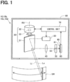
- a distance measuring device 10 includes a light emitting unit 20, a scanning unit 30, a light collecting optical system 40, an aperture unit 50, a light receiving unit 60, a control unit 70, and a housing 80.
- the light emitting unit 20, the scanning unit 30, the light collecting optical system 40, the aperture unit 50, the light receiving unit 60, and the control unit 70 are housed within the housing 80.
- the control unit 70 may be housed in a housing separate from the housing 80.
- the light emitting unit 20 emits irradiation light Lo.
- the light emitting unit 20 is equipped with an edge-emitting laser diode, and emits a linear laser light along a vertical direction of the distance measuring device 10 as irradiation light Lo from an end surface of the laser diode arranged parallel to the vertical direction of the distance measuring device 10.
- the scanning unit 30 includes a mirror 31 that reflects the irradiation light Lo, a motor 32 that rotates the mirror 31 around a rotation axis RX parallel to the vertical direction of the distance measuring device 10, and a rotation angle sensor 33 that detects a rotation angle of the mirror 31.
- the scanning unit 30 rotates the mirror 31 by the motor 32 to cause the irradiation light Lo emitted from the light emitting unit 20 to scan the distance measuring device 10 in a horizontal direction.
- a scanning range SR which is the range scanned by the irradiation light Lo
- the irradiation light Lo is reflected by the surface of the object
- the incident light Li which includes the reflected light of the irradiation light Lo, returns to the mirror 31.
- the incident light Li is reflected by the mirror 31 and enters the light collecting optical system 40.
- the light collecting optical system 40 includes at least one lens and collects the incident light Li.
- the aperture unit 50 is disposed behind the light collecting optical system 40 in a traveling direction of the incident light Li.
- the aperture unit 50 is made of a material having light blocking properties, and has an opening 55 that passes the incident light Li.
- the light receiving unit 60 is disposed behind the aperture unit 50 in the traveling direction of the incident light Li.
- the light receiving unit 60 has a light receiving surface 61 that receives the incident light Li.
- the incident light Li that has passed through the light collecting optical system 40 and the opening 55 of the aperture unit 50 is incident on the light receiving surface 61.
- the light receiving surface 61 is composed of a plurality of light receiving elements 68 that detect the incident light Li.
- the light receiving element 68 is a single photon avalanche diode.
- the control unit 70 is composed of a computer equipped with a CPU, a memory, an input/output interface for inputting and outputting signals from the outside, and an internal bus.
- the control unit 70 measures a distance between an object within the scanning range SR and the distance measuring device 10 by controlling the light emitting unit 20, the scanning unit 30, and the light receiving unit 60. Specifically, the control unit 70 causes the light emitting unit 20 to emit the irradiation light Lo in pulses, measures the time from when the irradiation light Lo is emitted to when the incident light Li is detected by the light receiving unit 60, and uses this time to calculate the distance between the distance measuring device 10 and a reflection point on the object.
- control unit 70 causes the light emitting unit 20 to emit the irradiation light Lo in pulses while rotating the mirror 31 using the motor 32.
- the control unit 70 detects the rotation angle of the mirror 31 when the incident light Li is detected by the rotation angle sensor 33, and uses the rotation angle to identify an azimuth angle of the reflection point on the object relative to the distance measuring device 10.
- the aperture unit 50 is configured in a flat plate shape.
- the opening 55 of the aperture unit 50 is formed in a slit shape, that is, in a long and narrow rectangular shape.
- the longitudinal direction of the opening 55 is parallel to the vertical direction Dv of the distance measuring device 10, and the lateral direction of the opening 55 is parallel to the horizontal direction Dh of the distance measuring device 10.
- the aperture unit 50 is disposed opposite to the light receiving surface 61 of the light receiving unit 60, and limits the amount of incident light Li passing through.
- the light collecting optical system 40 is disposed on the opposite side of the aperture unit 50 from the light receiving surface 61.
- the light collecting optical system 40 has a positive refractive power in the horizontal direction Dh and the vertical direction Dv.
- the refractive power of the light collecting optical system 40 differs in the horizontal direction Dh and the vertical direction Dv. Since the refractive power is equal to the reciprocal of the focal length, the focal length of the light collecting optical system 40 differs in the horizontal direction Dh and the vertical direction Dv.
- the focal length Fh of the light collecting optical system 40 in the horizontal direction Dh is shorter than the focal length Fv of the light collecting optical system 40 in the vertical direction Dv.
- the light collecting optical system 40, the aperture unit 50, and the light receiving unit 60 are arranged so that a center of the opening 55 is located on an extension of the optical axis OA of the light collecting optical system 40, the distance between a principal point OC of the light collecting optical system 40 and the center of the opening 55 is the same as the focal length Fh of the light collecting optical system 40 in the horizontal direction Dh, and the distance between the principal point OC of the light collecting optical system 40 and the light receiving surface 61 is the same as the focal length Fv of the light collecting optical system 40 in the vertical direction Dv.
- the light collecting optical system 40 focuses the incident light Li to the center of the opening 55 in the horizontal direction Dh, and focuses the incident light Li to the light receiving surface 61 in the vertical direction Dv. Therefore, the incident light Li is incident on the light receiving surface 61 defocused in the horizontal direction Dh, and the incident light Li is incident in just focus in the vertical direction Dv.
- the light collecting optical system 40 is simplified and illustrated as a single lens, but as shown in FIGS. 3 and 4 , in the present embodiment, the light collecting optical system 40 is composed of a first lens 41 and a second lens 42 arranged between the first lens 41 and the aperture unit 50.
- the first lens 41 is a cylindrical lens, more specifically, a concave cylindrical lens having a central axis parallel to the horizontal direction Dh, and is arranged so that its flat surface faces the mirror 31 and its cylindrical surface having a curvature in the vertical direction Dv faces the second lens 42.
- the second lens 42 is a spherical lens, more specifically, a plano-convex lens, and is arranged so that its spherical surface having curvature in the horizontal direction Dh and the vertical direction Dv faces the first lens 41 and its flat surface faces the aperture unit 50.
- the cylindrical surface referred to here means a curved surface obtained by cutting out a part of a cylindrical surface
- the spherical surface referred to here means a curved surface obtained by cutting out a part of a spherical surface.
- the light collecting optical system 40 is composed of two lenses 41 and 42, and therefore the focal lengths Fh and Fv of the light collecting optical system 40 described above are composite focal lengths of the two lenses 41 and 42.
- the light receiving surface 61 has a plurality of pixels 65 arranged in a lattice pattern along the horizontal direction Dh and the vertical direction Dv.
- Each pixel 65 is composed of a plurality of light receiving elements 68 arranged in a grid pattern along the horizontal direction Dh and the vertical direction Dv.
- each pixel 65 will be referred to as one pixel 65.
- a length of one pixel 65 in the horizontal direction Dh is longer than a length of one pixel 65 in the vertical direction Dv.
- the length of one pixel 65 in the horizontal direction Dh is longer than the length of the opening 55 in the horizontal direction Dh.
- the area on the light receiving surface 61 where the incident light Li is incident is indicated by a dashed line.
- the incident light Li is incident on one column of pixels 65.
- the area on which the incident light Li is incident does not move even if the mirror 31 is rotated.
- a position resolution of the distance measuring device 10 in the vertical direction Dv is determined by the center-to-center distance between adjacent pixels 65 in the vertical direction Dv.
- the azimuth angle resolution of the distance measuring device 10 is determined by the amount of change in the rotation angle of the mirror 31 during the time interval during which the irradiated light Lo is emitted. Since the light receiving elements 68 are single-photon avalanche diodes, the light intensity resolution of the distance measuring device 10 is determined by the number of light receiving elements 68 that constitute one pixel 65.
- the distance measuring device 10 is mounted on, for example, a vehicle and is used to measure the distance between the vehicle and an object such as a person or an obstacle. Since the reflectance of the irradiated light Lo differs between the asphalt surface and the white line on the road, the light intensity of the reflected light differs between when the irradiated light Lo is reflected by the asphalt surface and when the irradiated light Lo is reflected by the white line. Therefore, the position of the white line can be estimated using the light intensity at each reflection point measured by the distance measuring device 10. However, when the light intensity resolution is not high enough, it is not possible to distinguish between the white line and the asphalt surface, and therefore it is not possible to estimate the position of the white line.
- the light intensity resolution can be improved from 9 levels to 24 levels.
- the aperture unit 50 when the number of columns in the horizontal direction Dh of the light receiving elements 68 that constitute one pixel 65 is increased, the amount of disturbance light incident on one pixel 65 increases as the area of one pixel 65 increases, which may result in a decrease in the optical signal-to-noise ratio (S/N ratio).
- the amount of disturbance light incident on one pixel 65 increases by 8/3 times.
- the horizontal length Dh of the incident light Li at the light receiving surface 61 is increased by increasing the defocus amount, the amount of incident light Li incident on one pixel 65 does not increase, and the optical S/N ratio decreases by 3/8 times.
- the amount of defocus in the horizontal direction Dh when the amount of defocus in the horizontal direction Dh is increased in accordance with an increase in the number of columns in the horizontal direction Dh of the light receiving elements 68 that constitute one pixel 65, the amount of defocus in the vertical direction Dv also increases, thereby reducing the density of the incident light Li in the vertical direction Dv, reducing the amount of incident light Li incident on one pixel 65, and reducing the optical S/N ratio.
- the position resolution in the vertical direction Dv decreases when the number of rows in the vertical direction Dv of the light receiving elements 68 constituting one pixel 65 is increased so as not to reduce the optical S/N ratio.
- the aperture unit 50 having a slit-shaped opening 55 whose longitudinal direction is parallel to the vertical direction Dv and whose short direction is parallel to the horizontal direction Dh is arranged between the light collecting optical system 40 and the light receiving surface 61, so that even if the number of columns in the horizontal direction Dh of the light receiving elements 68 that constitute one pixel 65 is increased, the amount of disturbance light incident on one pixel 65 does not increase.
- the distance measuring device 10 is equipped with the light collecting optical system 40 having different refractive powers in the horizontal direction Dh and the vertical direction Dv, it is possible to suppress an increase in the defocus amount in the vertical direction Dv that accompanies an increase in the defocus amount in the horizontal direction Dh in accordance with an increase in the number of columns in the horizontal direction Dh of the light receiving elements 68 that constitute one pixel 65, thereby suppressing a decrease in the optical S/N ratio.
- the first lens 41 of the light collecting optical system 40 is a concave cylindrical lens and the second lens is a plano-convex lens
- the second lens is a plano-convex lens
- the length of the opening 55 of the aperture unit 50 in the horizontal direction Dh is shorter than the length of one pixel 65 in the horizontal direction Dh, and therefore the aperture unit 50 can effectively suppress an increase in the amount of disturbance light incident on one pixel 65.
- the light emitting unit 20 emits the linear irradiation light Lo along the vertical direction Dv
- the light receiving surface 61 has a plurality of pixels 65 arranged along the vertical direction Dv, so that the positional resolution in the vertical direction Dv can be ensured.
- the scanning unit 30 is provided that scans the irradiation light Lo emitted from the light emitting unit 20 along the horizontal direction Dh by rotating the mirror 31 and causes the incident light Li to be incident on the light collecting optical system 40, and the azimuth angle resolution is determined by the amount of change in the rotation angle of the mirror 31 during the time interval at which the irradiation light Lo is emitted. Therefore, even if the light intensity resolution is increased by increasing the number of columns in the horizontal direction Dh of the light receiving elements 68 that constitute one pixel 65, the azimuth angle resolution does not decrease.
- the configuration of a light collecting optical system 40b is different from that of the first embodiment.
- the first lens 41b of the light collecting optical system 40b is a convex cylindrical lens having a central axis parallel to the vertical direction Dv, and is arranged so that the cylindrical surface having a curvature in the horizontal direction Dh faces the mirror 31 and the flat surface faces the second lens 42b.
- the second lens 42b of the light collecting optical system 40b is a plano-convex lens, and is disposed so that its spherical surface having curvatures in the horizontal direction Dh and the vertical direction Dv faces the first lens 41b and its flat surface faces the aperture unit 50.
- the other configurations are the same as those of the first embodiment.
- the distance measuring device 10b of the second embodiment described above can increase the light intensity resolution while suppressing a decrease in the optical S/N ratio, and can suppress a decrease in the positional resolution in the vertical direction Dv.
- the configuration of a light collecting optical system 40c is different from that of the first embodiment.
- the first lens 41c of the light collecting optical system 40c is a plano-convex lens, and is arranged so that its spherical surface having curvature in the horizontal direction Dh and the vertical direction Dv faces the mirror 31, and its flat surface faces the second lens 42c.
- the second lens 42c of the light collecting optical system 40c is a concave cylindrical lens having a central axis parallel to the horizontal direction Dh, and is arranged so that its flat surface faces the first lens 41c and its cylindrical surface having a curvature in the vertical direction Dv faces the aperture unit 50.
- the other configurations are the same as those of the first embodiment.
- the distance measuring device 10c of the third embodiment described above can increase the light intensity resolution while suppressing a decrease in the optical S/N ratio, and can suppress a decrease in the positional resolution in the vertical direction Dv.
- the configuration of a light collecting optical system 40d is different from that of the first embodiment.
- the first lens 41d of the light collecting optical system 40d is a convex cylindrical lens having a central axis parallel to the horizontal direction Dh, and is arranged so that the cylindrical surface having a curvature in the vertical direction Dv faces the mirror 31 and the flat surface faces the second lens 42d.
- the second lens 42d of the light collecting optical system 40d is a convex cylindrical lens having a central axis parallel to the vertical direction Dv, and is arranged so that its cylindrical surface having a curvature in the horizontal direction Dh faces the first lens 41d and its flat surface faces the aperture unit 50.
- the other configurations are the same as those of the first embodiment.
- the distance measuring device 10d of the fourth embodiment described above can increase the light intensity resolution while suppressing a decrease in the optical S/N ratio, and can suppress a decrease in the positional resolution in the vertical direction Dv.
- the first lens 41d is a cylindrical lens having a central axis parallel to the horizontal direction Dh
- the second lens 42d is a cylindrical lens having a central axis parallel to the vertical direction Dv, so that the focal position in the horizontal direction Dh and the focal position in the vertical direction Dv of the light collecting optical system 40d can be adjusted independently of each other.
- the configurations of the light emitting unit 20e and the aperture unit 50e are different from those of the first embodiment.
- the other configurations are the same as those of the first embodiment.
- the light emitting unit 20e includes a vertical cavity surface emitting laser (VCSEL) as a light emitting element, and emits a plurality of dot-like irradiation lights Lo aligned along the vertical direction Dv.
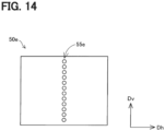
- the opening 55e of the aperture unit 50e is formed of a plurality of through holes aligned in the vertical direction Dv. Each through hole is circular in shape.
- the direction in which the multiple through holes are arranged is referred to as the longitudinal direction of the opening 55e, and the direction perpendicular to the longitudinal direction and the central axis of the through hole is referred to as the lateral direction of the opening 55e.
- the distance measuring device 10e of the fifth embodiment described above can increase the light intensity resolution while suppressing a decrease in the optical S/N ratio, and can suppress a decrease in the positional resolution in the vertical direction Dv.
- the distance measuring device 10e of the fifth embodiment may include the aperture unit 50 similar to that of the first embodiment, instead of the aperture unit 50e described above.
- the distance measuring device 10e may include the light collecting optical system 40b to 40d of any one of the second, third and fourth embodiments, instead of the light collecting optical system 40 of the first embodiment.
- the light emitting unit may irradiate the illumination light in a form of a plurality of dots aligned along the longitudinal direction of the opening.
- the optical system may include a cylindrical lens having a central axis parallel to the longitudinal direction of the opening, and a cylindrical lens having a central axis parallel to the lateral direction of the opening.
- the optical system may include a toroidal lens.
Landscapes
- Engineering & Computer Science (AREA)
- Physics & Mathematics (AREA)
- Computer Networks & Wireless Communication (AREA)
- General Physics & Mathematics (AREA)
- Radar, Positioning & Navigation (AREA)
- Remote Sensing (AREA)
- Electromagnetism (AREA)
- Optical Radar Systems And Details Thereof (AREA)
- Measurement Of Optical Distance (AREA)
Abstract
Description
- This application is based on
Japanese Application No. 2022-139817 filed on September 2, 2022 - The present disclosure relates to a distance measuring device.
- Patent Document 1 discloses a distance measuring device that measures a distance to an object by measuring the time it takes for a laser beam to be emitted, reflected by the object, and incident on a detector equipped with a single photon avalanche diode (SPAD).
- Patent Document 1:
US 10663586 B - Since an output signal of the SPAD is binary, in order to measure light intensity at multiple stages using the SPAD, one pixel on a light receiving surface must be composed of multiple SPADs. However, as a result of detailed study by the inventors, it was found that if the number of SPADs constituting one pixel is increased without changing a size of each SPAD, the amount of disturbance light incident on one pixel increases as an area of one pixel increases, and the ratio of the amount of signal light (laser light) to the amount of disturbance light incident on one pixel (hereinafter referred to as an optical S/N ratio) decreases. As a result, there is a possibility that it will not be possible to measure the distance to an object. Therefore, there is a need for a technique for improving a resolution of light intensity while suppressing a decrease in the optical S/N ratio (signal-to-noise ratio).
- The present disclosure can be realized as the following embodiments.
- According to one aspect of the present disclosure, a distance measuring device is provided. The distance measuring device includes a light emitting unit that emits irradiation light, a light receiving unit having a light receiving surface for receiving incident light including reflected light of the irradiation light, and in which one pixel is composed of a plurality of single-photon avalanche diodes, an aperture unit having an opening through which the incident light incident on the light receiving unit passes and limiting the amount of the incident light passing through, and an optical system having different refractive powers in a longitudinal direction of the opening and a lateral direction of the opening, the optical system focusing the incident light on the light receiving surface in the longitudinal direction and focusing the incident light on the opening in the lateral direction.
- According to the distance measuring device of this embodiment, it is possible to improve the resolution of the light intensity while suppressing the decrease in the optical S/N ratio.
- The above and other objects, features and advantages of the present disclosure will become more apparent from the following detailed description made with reference to the accompanying drawings. In the drawings:
-
FIG. 1 is an explanatory diagram showing a schematic configuration of a distance measuring device according to a first embodiment; -
FIG. 2 is a perspective view showing a light collecting optical system, an aperture unit, and a light receiving unit according to the first embodiment; -
FIG. 3 is a first cross-sectional view showing a configuration of the light collecting optical system according to the first embodiment; -
FIG. 4 is a second cross-sectional view showing the configuration of the light collecting optical system of the first embodiment; -
FIG. 5 is an explanatory diagram showing the configuration of a light receiving surface of the first embodiment; -
FIG. 6 is an explanatory diagram showing how the number of columns of light receiving elements constituting one pixel is increased; -
FIG. 7 is a first cross-sectional view showing a configuration of a light collecting optical system according to a second embodiment; -
FIG. 8 is a second cross-sectional view showing the configuration of the light collecting optical system of the second embodiment; -
FIG. 9 is a first cross-sectional view showing a configuration of a light collecting optical system according to a third embodiment; -
FIG. 10 is a second cross-sectional view showing the configuration of the light collecting optical system of the third embodiment; -
FIG. 11 is a first cross-sectional view showing a configuration of a light collecting optical system according to a fourth embodiment; -
FIG. 12 is a second cross-sectional view showing the configuration of the light collecting optical system of the fourth embodiment; -
FIG. 13 is an explanatory diagram showing a schematic configuration of a distance measuring device according to a fifth embodiment; and -
FIG. 14 is an explanatory diagram showing a configuration of an aperture unit according to a fifth embodiment. - As shown in
FIG. 1 , in the present embodiment, a distance measuring device 10 includes alight emitting unit 20, ascanning unit 30, a light collectingoptical system 40, anaperture unit 50, alight receiving unit 60, acontrol unit 70, and ahousing 80. Thelight emitting unit 20, thescanning unit 30, the light collectingoptical system 40, theaperture unit 50, thelight receiving unit 60, and thecontrol unit 70 are housed within thehousing 80. Thecontrol unit 70 may be housed in a housing separate from thehousing 80. - The
light emitting unit 20 emits irradiation light Lo. In the present embodiment, thelight emitting unit 20 is equipped with an edge-emitting laser diode, and emits a linear laser light along a vertical direction of the distance measuring device 10 as irradiation light Lo from an end surface of the laser diode arranged parallel to the vertical direction of the distance measuring device 10. Thescanning unit 30 includes amirror 31 that reflects the irradiation light Lo, amotor 32 that rotates themirror 31 around a rotation axis RX parallel to the vertical direction of the distance measuring device 10, and arotation angle sensor 33 that detects a rotation angle of themirror 31. Thescanning unit 30 rotates themirror 31 by themotor 32 to cause the irradiation light Lo emitted from thelight emitting unit 20 to scan the distance measuring device 10 in a horizontal direction. When an object is present within a scanning range SR, which is the range scanned by the irradiation light Lo, the irradiation light Lo is reflected by the surface of the object, and the incident light Li, which includes the reflected light of the irradiation light Lo, returns to themirror 31. The incident light Li is reflected by themirror 31 and enters the light collectingoptical system 40. - The light collecting
optical system 40 includes at least one lens and collects the incident light Li. Theaperture unit 50 is disposed behind the light collectingoptical system 40 in a traveling direction of the incident light Li. Theaperture unit 50 is made of a material having light blocking properties, and has anopening 55 that passes the incident light Li. Thelight receiving unit 60 is disposed behind theaperture unit 50 in the traveling direction of the incident light Li. Thelight receiving unit 60 has alight receiving surface 61 that receives the incident light Li. The incident light Li that has passed through the light collectingoptical system 40 and theopening 55 of theaperture unit 50 is incident on thelight receiving surface 61. Thelight receiving surface 61 is composed of a plurality oflight receiving elements 68 that detect the incident light Li. In the present embodiment, thelight receiving element 68 is a single photon avalanche diode. - The
control unit 70 is composed of a computer equipped with a CPU, a memory, an input/output interface for inputting and outputting signals from the outside, and an internal bus. Thecontrol unit 70 measures a distance between an object within the scanning range SR and the distance measuring device 10 by controlling thelight emitting unit 20, thescanning unit 30, and thelight receiving unit 60. Specifically, thecontrol unit 70 causes thelight emitting unit 20 to emit the irradiation light Lo in pulses, measures the time from when the irradiation light Lo is emitted to when the incident light Li is detected by thelight receiving unit 60, and uses this time to calculate the distance between the distance measuring device 10 and a reflection point on the object. In the present embodiment, thecontrol unit 70 causes thelight emitting unit 20 to emit the irradiation light Lo in pulses while rotating themirror 31 using themotor 32. Thecontrol unit 70 detects the rotation angle of themirror 31 when the incident light Li is detected by therotation angle sensor 33, and uses the rotation angle to identify an azimuth angle of the reflection point on the object relative to the distance measuring device 10. - As shown in
FIG. 2 , in the present embodiment, theaperture unit 50 is configured in a flat plate shape. The opening 55 of theaperture unit 50 is formed in a slit shape, that is, in a long and narrow rectangular shape. The longitudinal direction of theopening 55 is parallel to the vertical direction Dv of the distance measuring device 10, and the lateral direction of theopening 55 is parallel to the horizontal direction Dh of the distance measuring device 10. Theaperture unit 50 is disposed opposite to thelight receiving surface 61 of thelight receiving unit 60, and limits the amount of incident light Li passing through. - The light collecting
optical system 40 is disposed on the opposite side of theaperture unit 50 from thelight receiving surface 61. The light collectingoptical system 40 has a positive refractive power in the horizontal direction Dh and the vertical direction Dv. The refractive power of the light collectingoptical system 40 differs in the horizontal direction Dh and the vertical direction Dv. Since the refractive power is equal to the reciprocal of the focal length, the focal length of the light collectingoptical system 40 differs in the horizontal direction Dh and the vertical direction Dv. In the present embodiment, the focal length Fh of the light collectingoptical system 40 in the horizontal direction Dh is shorter than the focal length Fv of the light collectingoptical system 40 in the vertical direction Dv. The light collectingoptical system 40, theaperture unit 50, and thelight receiving unit 60 are arranged so that a center of theopening 55 is located on an extension of the optical axis OA of the light collectingoptical system 40, the distance between a principal point OC of the light collectingoptical system 40 and the center of theopening 55 is the same as the focal length Fh of the light collectingoptical system 40 in the horizontal direction Dh, and the distance between the principal point OC of the light collectingoptical system 40 and thelight receiving surface 61 is the same as the focal length Fv of the light collectingoptical system 40 in the vertical direction Dv. The light collectingoptical system 40 focuses the incident light Li to the center of theopening 55 in the horizontal direction Dh, and focuses the incident light Li to thelight receiving surface 61 in the vertical direction Dv. Therefore, the incident light Li is incident on thelight receiving surface 61 defocused in the horizontal direction Dh, and the incident light Li is incident in just focus in the vertical direction Dv. - In
FIGS. 1 and2 , the light collectingoptical system 40 is simplified and illustrated as a single lens, but as shown inFIGS. 3 and 4 , in the present embodiment, the light collectingoptical system 40 is composed of afirst lens 41 and asecond lens 42 arranged between thefirst lens 41 and theaperture unit 50. In the present embodiment, thefirst lens 41 is a cylindrical lens, more specifically, a concave cylindrical lens having a central axis parallel to the horizontal direction Dh, and is arranged so that its flat surface faces themirror 31 and its cylindrical surface having a curvature in the vertical direction Dv faces thesecond lens 42. Thesecond lens 42 is a spherical lens, more specifically, a plano-convex lens, and is arranged so that its spherical surface having curvature in the horizontal direction Dh and the vertical direction Dv faces thefirst lens 41 and its flat surface faces theaperture unit 50. The cylindrical surface referred to here means a curved surface obtained by cutting out a part of a cylindrical surface, and the spherical surface referred to here means a curved surface obtained by cutting out a part of a spherical surface. In the present embodiment, the light collectingoptical system 40 is composed of twolenses optical system 40 described above are composite focal lengths of the twolenses - As shown in
FIG. 5 , thelight receiving surface 61 has a plurality ofpixels 65 arranged in a lattice pattern along the horizontal direction Dh and the vertical direction Dv. Eachpixel 65 is composed of a plurality of light receivingelements 68 arranged in a grid pattern along the horizontal direction Dh and the vertical direction Dv. In the following description, eachpixel 65 will be referred to as onepixel 65. In the present embodiment, a length of onepixel 65 in the horizontal direction Dh is longer than a length of onepixel 65 in the vertical direction Dv. The length of onepixel 65 in the horizontal direction Dh is longer than the length of theopening 55 in the horizontal direction Dh. InFIG. 5 , the area on thelight receiving surface 61 where the incident light Li is incident is indicated by a dashed line. In the present embodiment, the incident light Li is incident on one column ofpixels 65. In the present embodiment, the area on which the incident light Li is incident does not move even if themirror 31 is rotated. - A position resolution of the distance measuring device 10 in the vertical direction Dv is determined by the center-to-center distance between
adjacent pixels 65 in the vertical direction Dv. The azimuth angle resolution of the distance measuring device 10 is determined by the amount of change in the rotation angle of themirror 31 during the time interval during which the irradiated light Lo is emitted. Since thelight receiving elements 68 are single-photon avalanche diodes, the light intensity resolution of the distance measuring device 10 is determined by the number of light receivingelements 68 that constitute onepixel 65. - The distance measuring device 10 is mounted on, for example, a vehicle and is used to measure the distance between the vehicle and an object such as a person or an obstacle. Since the reflectance of the irradiated light Lo differs between the asphalt surface and the white line on the road, the light intensity of the reflected light differs between when the irradiated light Lo is reflected by the asphalt surface and when the irradiated light Lo is reflected by the white line. Therefore, the position of the white line can be estimated using the light intensity at each reflection point measured by the distance measuring device 10. However, when the light intensity resolution is not high enough, it is not possible to distinguish between the white line and the asphalt surface, and therefore it is not possible to estimate the position of the white line.
- As shown in
FIG. 6 , when the number of light receivingelements 68 constituting onepixel 65 is increased from 9 (=3×3 (vertical×horizontal)) to 24 (=3×8 (vertical×horizontal)), the light intensity resolution can be improved from 9 levels to 24 levels. However, in a configuration in which theaperture unit 50 is not provided, when the number of columns in the horizontal direction Dh of thelight receiving elements 68 that constitute onepixel 65 is increased, the amount of disturbance light incident on onepixel 65 increases as the area of onepixel 65 increases, which may result in a decrease in the optical signal-to-noise ratio (S/N ratio). For example, in an environment in which disturbance light is uniformly incident on thelight receiving surface 61 from between the light collectingoptical system 40 and thelight receiving surface 61, the amount of disturbance light incident on onepixel 65 increases by 8/3 times. However, even if the horizontal length Dh of the incident light Li at thelight receiving surface 61 is increased by increasing the defocus amount, the amount of incident light Li incident on onepixel 65 does not increase, and the optical S/N ratio decreases by 3/8 times. - Furthermore, in a configuration in which the refractive power of the light collecting
optical system 40 is the same in the horizontal direction Dh and the vertical direction Dv, when the amount of defocus in the horizontal direction Dh is increased in accordance with an increase in the number of columns in the horizontal direction Dh of thelight receiving elements 68 that constitute onepixel 65, the amount of defocus in the vertical direction Dv also increases, thereby reducing the density of the incident light Li in the vertical direction Dv, reducing the amount of incident light Li incident on onepixel 65, and reducing the optical S/N ratio. When the number of rows in the vertical direction Dv of thelight receiving elements 68 constituting onepixel 65 is increased so as not to reduce the optical S/N ratio, the position resolution in the vertical direction Dv decreases. - In contrast, according to the distance measuring device 10 of the present embodiment described above, the
aperture unit 50 having a slit-shapedopening 55 whose longitudinal direction is parallel to the vertical direction Dv and whose short direction is parallel to the horizontal direction Dh is arranged between the light collectingoptical system 40 and thelight receiving surface 61, so that even if the number of columns in the horizontal direction Dh of thelight receiving elements 68 that constitute onepixel 65 is increased, the amount of disturbance light incident on onepixel 65 does not increase. In addition, since the distance measuring device 10 is equipped with the light collectingoptical system 40 having different refractive powers in the horizontal direction Dh and the vertical direction Dv, it is possible to suppress an increase in the defocus amount in the vertical direction Dv that accompanies an increase in the defocus amount in the horizontal direction Dh in accordance with an increase in the number of columns in the horizontal direction Dh of thelight receiving elements 68 that constitute onepixel 65, thereby suppressing a decrease in the optical S/N ratio. Therefore, by increasing the number of columns in the horizontal direction Dh of thelight receiving elements 68 that constitute onepixel 65 and increasing the amount of defocus in the horizontal direction Dh without changing the amount of defocus in the vertical direction Dv, it is possible to increase the light intensity resolution while suppressing a decrease in the optical S/N ratio, and also to suppress a decrease in the positional resolution in the vertical direction Dv. - Furthermore, in the present embodiment, since the
first lens 41 of the light collectingoptical system 40 is a concave cylindrical lens and the second lens is a plano-convex lens, by adjusting the position and orientation of thesecond lens 42 and then adjusting the position and orientation of thefirst lens 41, it is possible to easily align the light collectingoptical system 40, theaperture unit 50, and thelight receiving surface 61. In addition, it is also possible to align the light collectingoptical system 40, theaperture unit 50, and thelight receiving surface 61 by adjusting the position and orientation of theaperture unit 50 and adjusting the position and orientation of thelight receiving surface 61 without moving thefirst lens 41 and thesecond lens 42. - In addition, in the present embodiment, the length of the
opening 55 of theaperture unit 50 in the horizontal direction Dh is shorter than the length of onepixel 65 in the horizontal direction Dh, and therefore theaperture unit 50 can effectively suppress an increase in the amount of disturbance light incident on onepixel 65. - In addition, in the present embodiment, the
light emitting unit 20 emits the linear irradiation light Lo along the vertical direction Dv, and thelight receiving surface 61 has a plurality ofpixels 65 arranged along the vertical direction Dv, so that the positional resolution in the vertical direction Dv can be ensured. - In addition, in the present embodiment, the
scanning unit 30 is provided that scans the irradiation light Lo emitted from thelight emitting unit 20 along the horizontal direction Dh by rotating themirror 31 and causes the incident light Li to be incident on the light collectingoptical system 40, and the azimuth angle resolution is determined by the amount of change in the rotation angle of themirror 31 during the time interval at which the irradiation light Lo is emitted. Therefore, even if the light intensity resolution is increased by increasing the number of columns in the horizontal direction Dh of thelight receiving elements 68 that constitute onepixel 65, the azimuth angle resolution does not decrease. - As shown in
FIGS. 7 and 8 , in a distance measuring device 10b of the second embodiment, the configuration of a light collectingoptical system 40b is different from that of the first embodiment. Specifically, in the present embodiment, thefirst lens 41b of the light collectingoptical system 40b is a convex cylindrical lens having a central axis parallel to the vertical direction Dv, and is arranged so that the cylindrical surface having a curvature in the horizontal direction Dh faces themirror 31 and the flat surface faces thesecond lens 42b. Thesecond lens 42b of the light collectingoptical system 40b is a plano-convex lens, and is disposed so that its spherical surface having curvatures in the horizontal direction Dh and the vertical direction Dv faces thefirst lens 41b and its flat surface faces theaperture unit 50. The other configurations are the same as those of the first embodiment. The distance measuring device 10b of the second embodiment described above, like the first embodiment, can increase the light intensity resolution while suppressing a decrease in the optical S/N ratio, and can suppress a decrease in the positional resolution in the vertical direction Dv. - As shown in
FIGS. 9 and 10 , in the distance measuring device 10c of the third embodiment, the configuration of a light collectingoptical system 40c is different from that of the first embodiment. Specifically, in the present embodiment, thefirst lens 41c of the light collectingoptical system 40c is a plano-convex lens, and is arranged so that its spherical surface having curvature in the horizontal direction Dh and the vertical direction Dv faces themirror 31, and its flat surface faces thesecond lens 42c. Thesecond lens 42c of the light collectingoptical system 40c is a concave cylindrical lens having a central axis parallel to the horizontal direction Dh, and is arranged so that its flat surface faces thefirst lens 41c and its cylindrical surface having a curvature in the vertical direction Dv faces theaperture unit 50. The other configurations are the same as those of the first embodiment. The distance measuring device 10c of the third embodiment described above, like the first embodiment, can increase the light intensity resolution while suppressing a decrease in the optical S/N ratio, and can suppress a decrease in the positional resolution in the vertical direction Dv. - As shown in
FIGS. 11 and 12 , in a distance measuring device 10d of the fourth embodiment, the configuration of a light collectingoptical system 40d is different from that of the first embodiment. Specifically, in the present embodiment, thefirst lens 41d of the light collectingoptical system 40d is a convex cylindrical lens having a central axis parallel to the horizontal direction Dh, and is arranged so that the cylindrical surface having a curvature in the vertical direction Dv faces themirror 31 and the flat surface faces thesecond lens 42d. Thesecond lens 42d of the light collectingoptical system 40d is a convex cylindrical lens having a central axis parallel to the vertical direction Dv, and is arranged so that its cylindrical surface having a curvature in the horizontal direction Dh faces thefirst lens 41d and its flat surface faces theaperture unit 50. The other configurations are the same as those of the first embodiment. The distance measuring device 10d of the fourth embodiment described above, like the first embodiment, can increase the light intensity resolution while suppressing a decrease in the optical S/N ratio, and can suppress a decrease in the positional resolution in the vertical direction Dv. In addition, in the present embodiment, thefirst lens 41d is a cylindrical lens having a central axis parallel to the horizontal direction Dh, and thesecond lens 42d is a cylindrical lens having a central axis parallel to the vertical direction Dv, so that the focal position in the horizontal direction Dh and the focal position in the vertical direction Dv of the light collectingoptical system 40d can be adjusted independently of each other. - As shown in
FIGS. 13 and14 , in adistance measuring device 10e of the fifth embodiment, the configurations of thelight emitting unit 20e and theaperture unit 50e are different from those of the first embodiment. The other configurations are the same as those of the first embodiment. As shown inFIG. 13 , in the present embodiment, thelight emitting unit 20e includes a vertical cavity surface emitting laser (VCSEL) as a light emitting element, and emits a plurality of dot-like irradiation lights Lo aligned along the vertical direction Dv. As shown inFIG. 14 , theopening 55e of theaperture unit 50e is formed of a plurality of through holes aligned in the vertical direction Dv. Each through hole is circular in shape. In the present embodiment, the direction in which the multiple through holes are arranged is referred to as the longitudinal direction of theopening 55e, and the direction perpendicular to the longitudinal direction and the central axis of the through hole is referred to as the lateral direction of theopening 55e. Thedistance measuring device 10e of the fifth embodiment described above, like the first embodiment, can increase the light intensity resolution while suppressing a decrease in the optical S/N ratio, and can suppress a decrease in the positional resolution in the vertical direction Dv. Thedistance measuring device 10e of the fifth embodiment may include theaperture unit 50 similar to that of the first embodiment, instead of theaperture unit 50e described above. Thedistance measuring device 10e may include the light collectingoptical system 40b to 40d of any one of the second, third and fourth embodiments, instead of the light collectingoptical system 40 of the first embodiment. - (F1) In the distance measuring devices 10 to 10e of the above-mentioned embodiments, the light collecting
optical system 40 to 40d is composed of twolenses 41 to 41d and 42 to 42d. Alternatively, the light collectingoptical systems 40 to 40d may be configured with a single lens having different refractive powers in the horizontal direction Dh and the vertical direction Dv. The light collectingoptical system 40 may be composed of, for example, one toroidal lens, one toric lens, or one anamorphic lens. In this case, the light collectingoptical systems 40 to 40d can be made smaller than in a configuration in which the light collectingoptical systems 40 to 40d are composed of a plurality of lenses. - (F2) The distance measuring devices 10 to 10e of the above-described embodiments include the
scanning unit 30 that scans the irradiated light Lo along the horizontal direction Dh. In contrast, the distance measuring devices 10 to 10e do not need to include thescanning unit 30. - The present disclosure should not be limited to the embodiments described above, and various other embodiments may be implemented without departing from the scope of the present disclosure. For example, in order to solve some or all of the above problems, or to achieve some or all of the above effects, the technical features in the embodiments can be replaced or combined as appropriate. Also, if the technical features are not described as essential in the present specification, they can be deleted as appropriate.
- A distance measuring device (10) includes a light emitting unit (20) that emits irradiation light (Lo), a light receiving unit (60) having a light receiving surface (61) for receiving incident light (Li) including reflected light of the irradiation light, and in which one pixel (65) is composed of a plurality of single-photon avalanche diodes (68), an aperture unit (50) having an opening (55) through which the incident light incident on the light receiving unit passes and limiting the amount of the incident light passing through, and an optical system (40) having different refractive powers in a longitudinal direction of the opening and a lateral direction of the opening, the optical system focusing the incident light on the light receiving surface in the longitudinal direction and focusing the incident light on the opening in the lateral direction.
- The distance measuring device described in the feature 1 may include a scanning unit (30) having a mirror (31) that reflects the irradiation light and the incident light, and rotating the mirror around a rotation axis (RX) parallel to the longitudinal direction of the opening, thereby scanning the irradiation light emitted from the light emitting unit along the lateral direction and causing the incident light to enter the optical system.
- In the distance measuring device according to the feature 1 or 2, a length of one pixel in the lateral direction of the opening may be longer than a length of one pixel in the longitudinal direction of the opening.
- In the distance measuring device according to any one of the features 1 to 3, the light emitting unit may irradiate a linear irradiation light along the longitudinal direction of the opening.
- In the distance measuring device according to any one of the features 1 to 3, the light emitting unit may irradiate the illumination light in a form of a plurality of dots aligned along the longitudinal direction of the opening.
- In the distance measuring device according to any one of the features 1 to 5, the optical system may include a spherical lens and a cylindrical lens.
- In the distance measuring device described in any one of the features 1 to 5, the optical system may include a cylindrical lens having a central axis parallel to the longitudinal direction of the opening, and a cylindrical lens having a central axis parallel to the lateral direction of the opening.
- In the distance measuring device according to any one of the features 1 to 5, the optical system may include a toroidal lens.
- Although the present disclosure has been described in accordance with the embodiments, it is understood that the present disclosure is not limited to the embodiments and structures disclosed therein. The present disclosure encompasses various modifications and variations within the scope of equivalents. In addition, while the various combinations and configurations, which are preferred, other combinations and configurations, including more, less or only a single element, are also within the spirit and scope of the present disclosure.
Claims (8)
- A distance measuring device (10), comprising:a light emitting unit (20) configured to emit irradiation light (Lo);a light receiving unit (60) having a light receiving surface (61) for receiving incident light (Li) including reflected light of the irradiation light, and in which one pixel (65) is composed of a plurality of single-photon avalanche diodes (68);an aperture unit (50) having an opening (55) through which incident light incident on the light receiving unit passes and limiting an amount of the incident light passing through; andan optical system (40) having different refractive powers in a longitudinal direction of the opening and a lateral direction of the opening, the optical system focusing the incident light on the light receiving surface in the longitudinal direction and focusing the incident light on the opening in the lateral direction.
- The distance measuring device according to claim 1, further comprising,
a scanning unit (30) having a mirror (31) that reflects the irradiation light and the incident light, and rotating the mirror around a rotation axis (RX) parallel to the longitudinal direction of the opening, thereby scanning the irradiation light emitted from the light emitting unit along the lateral direction and causing the incident light to enter the optical system. - The distance measuring device according to claim 1, wherein
a length of one pixel in the lateral direction of the opening is longer than a length of one pixel in the longitudinal direction of the opening. - The distance measuring device according to claim 1, wherein
the light emitting unit emits a linear irradiation light along the longitudinal direction of the opening. - The distance measuring device according to claim 1, wherein
the light emitting unit irradiates the irradiation light in a form of multiple dots aligned along the longitudinal direction of the opening. - The distance measuring device according to claim 1, wherein
the optical system includes a spherical lens and a cylindrical lens. - The distance measuring device according to claim 1, wherein
the optical system includes a cylindrical lens having a central axis parallel to the longitudinal direction of the opening, and a cylindrical lens having a central axis parallel to the lateral direction of the opening. - The distance measuring device according to claim 1, wherein
the optical system includes a toroidal lens.
Applications Claiming Priority (2)
| Application Number | Priority Date | Filing Date | Title |
|---|---|---|---|
| JP2022139817A JP7732422B2 (en) | 2022-09-02 | 2022-09-02 | distance measuring device |
| PCT/JP2023/029257 WO2024048242A1 (en) | 2022-09-02 | 2023-08-10 | Ranging device |
Publications (2)
| Publication Number | Publication Date |
|---|---|
| EP4582835A1 true EP4582835A1 (en) | 2025-07-09 |
| EP4582835A4 EP4582835A4 (en) | 2025-11-26 |
Family
ID=90099366
Family Applications (1)
| Application Number | Title | Priority Date | Filing Date |
|---|---|---|---|
| EP23860007.6A Pending EP4582835A4 (en) | 2022-09-02 | 2023-08-10 | TELEMETRY DEVICE |
Country Status (5)
| Country | Link |
|---|---|
| US (1) | US20250164613A1 (en) |
| EP (1) | EP4582835A4 (en) |
| JP (1) | JP7732422B2 (en) |
| CN (1) | CN119522378A (en) |
| WO (1) | WO2024048242A1 (en) |
Family Cites Families (10)
| Publication number | Priority date | Publication date | Assignee | Title |
|---|---|---|---|---|
| JP2012202776A (en) * | 2011-03-24 | 2012-10-22 | Toyota Central R&D Labs Inc | Distance measuring device |
| JP2014006110A (en) * | 2012-06-22 | 2014-01-16 | Konica Minolta Inc | Laser radar |
| JP2015212647A (en) * | 2014-05-02 | 2015-11-26 | 株式会社リコー | Object detection device and sensing device |
| US20180164414A1 (en) * | 2016-12-13 | 2018-06-14 | Sensl Technologies Ltd. | LiDAR Apparatus |
| JP7154230B2 (en) | 2017-05-15 | 2022-10-17 | アウスター インコーポレイテッド | Optical Imaging Transmitter with Enhanced Brightness |
| JP6519033B1 (en) * | 2018-07-03 | 2019-05-29 | Dolphin株式会社 | Object detection device, object detection method, and design method of object detection device |
| US11333748B2 (en) * | 2018-09-17 | 2022-05-17 | Waymo Llc | Array of light detectors with corresponding array of optical elements |
| US11550038B2 (en) * | 2018-09-26 | 2023-01-10 | Apple Inc. | LIDAR system with anamorphic objective lens |
| JP2020187042A (en) * | 2019-05-16 | 2020-11-19 | 株式会社デンソー | Optical ranging device |
| US11604259B2 (en) * | 2019-10-14 | 2023-03-14 | Infineon Technologies Ag | Scanning LIDAR receiver with a silicon photomultiplier detector |
-
2022
- 2022-09-02 JP JP2022139817A patent/JP7732422B2/en active Active
-
2023
- 2023-08-10 CN CN202380052316.2A patent/CN119522378A/en active Pending
- 2023-08-10 EP EP23860007.6A patent/EP4582835A4/en active Pending
- 2023-08-10 WO PCT/JP2023/029257 patent/WO2024048242A1/en not_active Ceased
-
2025
- 2025-01-17 US US19/027,521 patent/US20250164613A1/en active Pending
Also Published As
| Publication number | Publication date |
|---|---|
| JP2024035389A (en) | 2024-03-14 |
| WO2024048242A1 (en) | 2024-03-07 |
| US20250164613A1 (en) | 2025-05-22 |
| JP7732422B2 (en) | 2025-09-02 |
| CN119522378A (en) | 2025-02-25 |
| EP4582835A4 (en) | 2025-11-26 |
Similar Documents
| Publication | Publication Date | Title |
|---|---|---|
| US12461206B2 (en) | LIDAR receiver using a waveguide and an aperture | |
| US9568358B2 (en) | Optical measurement device and vehicle | |
| US11585902B2 (en) | Optical designs using cylindrical lenses for improved resolution in lidar systems | |
| US9285266B2 (en) | Object detector including a light source with light emitting region of a first size in a first direction and a second size in a second direction | |
| US10996322B2 (en) | Lidar sensor | |
| US11867808B2 (en) | Waveguide diffusers for LIDARs | |
| US11137483B2 (en) | Light scanner | |
| US10802115B2 (en) | Light projecting and receiving device, and laser radar device provided with same | |
| US20230003843A1 (en) | Transmission unit and lidar device with optical homogenizer | |
| EP4582835A1 (en) | Ranging device | |
| US12242001B2 (en) | Scanning lidar with flood illumination for near-field detection | |
| CN113874754A (en) | Distance measuring device | |
| US20220107397A1 (en) | Lidar system | |
| JP2023073072A (en) | optical device | |
| WO2024084859A1 (en) | Optical sensor and light reception module | |
| WO2026023382A1 (en) | Light-emitting module and optical device | |
| WO2025150344A1 (en) | Measurement device | |
| WO2025218345A1 (en) | Laser detection assembly, laser radar receiving system, and laser radar system | |
| JP2024017519A (en) | Measuring device, receiver, and emitter | |
| JP2014228351A (en) | Object recognition device |
Legal Events
| Date | Code | Title | Description |
|---|---|---|---|
| STAA | Information on the status of an ep patent application or granted ep patent |
Free format text: STATUS: THE INTERNATIONAL PUBLICATION HAS BEEN MADE |
|
| PUAI | Public reference made under article 153(3) epc to a published international application that has entered the european phase |
Free format text: ORIGINAL CODE: 0009012 |
|
| STAA | Information on the status of an ep patent application or granted ep patent |
Free format text: STATUS: REQUEST FOR EXAMINATION WAS MADE |
|
| 17P | Request for examination filed |
Effective date: 20241112 |
|
| AK | Designated contracting states |
Kind code of ref document: A1 Designated state(s): AL AT BE BG CH CY CZ DE DK EE ES FI FR GB GR HR HU IE IS IT LI LT LU LV MC ME MK MT NL NO PL PT RO RS SE SI SK SM TR |
|
| STAA | Information on the status of an ep patent application or granted ep patent |
Free format text: STATUS: EXAMINATION IS IN PROGRESS |
|
| A4 | Supplementary search report drawn up and despatched |
Effective date: 20251027 |
|
| RIC1 | Information provided on ipc code assigned before grant |
Ipc: G01S 7/481 20060101AFI20251021BHEP Ipc: G01S 7/4914 20200101ALI20251021BHEP Ipc: G01S 17/894 20200101ALI20251021BHEP Ipc: G01S 7/4865 20200101ALI20251021BHEP Ipc: G01S 17/10 20200101ALI20251021BHEP Ipc: G01S 17/42 20060101ALI20251021BHEP Ipc: G01S 17/931 20200101ALI20251021BHEP |
|
| DAV | Request for validation of the european patent (deleted) | ||
| DAX | Request for extension of the european patent (deleted) | ||
| 17Q | First examination report despatched |
Effective date: 20251121 |