EP4582763A1 - Heat exchanger and use thereof - Google Patents
Heat exchanger and use thereof Download PDFInfo
- Publication number
- EP4582763A1 EP4582763A1 EP24020003.0A EP24020003A EP4582763A1 EP 4582763 A1 EP4582763 A1 EP 4582763A1 EP 24020003 A EP24020003 A EP 24020003A EP 4582763 A1 EP4582763 A1 EP 4582763A1
- Authority
- EP
- European Patent Office
- Prior art keywords
- heat exchanger
- connecting piece
- line section
- drain line
- heat
- Prior art date
- Legal status (The legal status is an assumption and is not a legal conclusion. Google has not performed a legal analysis and makes no representation as to the accuracy of the status listed.)
- Pending
Links
Images



Classifications
-
- F—MECHANICAL ENGINEERING; LIGHTING; HEATING; WEAPONS; BLASTING
- F28—HEAT EXCHANGE IN GENERAL
- F28B—STEAM OR VAPOUR CONDENSERS
- F28B1/00—Condensers in which the steam or vapour is separate from the cooling medium by walls, e.g. surface condenser
- F28B1/02—Condensers in which the steam or vapour is separate from the cooling medium by walls, e.g. surface condenser using water or other liquid as the cooling medium
-
- F—MECHANICAL ENGINEERING; LIGHTING; HEATING; WEAPONS; BLASTING
- F28—HEAT EXCHANGE IN GENERAL
- F28B—STEAM OR VAPOUR CONDENSERS
- F28B9/00—Auxiliary systems, arrangements, or devices
- F28B9/08—Auxiliary systems, arrangements, or devices for collecting and removing condensate
-
- F—MECHANICAL ENGINEERING; LIGHTING; HEATING; WEAPONS; BLASTING
- F28—HEAT EXCHANGE IN GENERAL
- F28F—DETAILS OF HEAT-EXCHANGE AND HEAT-TRANSFER APPARATUS, OF GENERAL APPLICATION
- F28F17/00—Removing ice or water from heat-exchange apparatus
- F28F17/005—Means for draining condensates from heat exchangers, e.g. from evaporators
-
- F—MECHANICAL ENGINEERING; LIGHTING; HEATING; WEAPONS; BLASTING
- F28—HEAT EXCHANGE IN GENERAL
- F28D—HEAT-EXCHANGE APPARATUS, NOT PROVIDED FOR IN ANOTHER SUBCLASS, IN WHICH THE HEAT-EXCHANGE MEDIA DO NOT COME INTO DIRECT CONTACT
- F28D7/00—Heat-exchange apparatus having stationary tubular conduit assemblies for both heat-exchange media, the media being in contact with different sides of a conduit wall
- F28D7/06—Heat-exchange apparatus having stationary tubular conduit assemblies for both heat-exchange media, the media being in contact with different sides of a conduit wall the conduits having a single U-bend
-
- F—MECHANICAL ENGINEERING; LIGHTING; HEATING; WEAPONS; BLASTING
- F28—HEAT EXCHANGE IN GENERAL
- F28F—DETAILS OF HEAT-EXCHANGE AND HEAT-TRANSFER APPARATUS, OF GENERAL APPLICATION
- F28F2265/00—Safety or protection arrangements; Arrangements for preventing malfunction
- F28F2265/06—Safety or protection arrangements; Arrangements for preventing malfunction by using means for draining heat exchange media from heat exchangers
-
- F—MECHANICAL ENGINEERING; LIGHTING; HEATING; WEAPONS; BLASTING
- F28—HEAT EXCHANGE IN GENERAL
- F28F—DETAILS OF HEAT-EXCHANGE AND HEAT-TRANSFER APPARATUS, OF GENERAL APPLICATION
- F28F2265/00—Safety or protection arrangements; Arrangements for preventing malfunction
- F28F2265/22—Safety or protection arrangements; Arrangements for preventing malfunction for draining
Definitions
- Heat exchangers and their use for a variety of process applications are known in the art.
- Heat exchangers can be used as condensers, wherein it may be necessary to subcool the condensate produced. This is usually achieved by blocking the condensate discharge pipe causing the condensate to accumulate inside the heat exchanger and cover the heat exchanger tubes.
- a number of tubes should be covered to this purpose, on the other hand, if too many tubes are covered, this will impede the condensation process.
- horizontal baffle cut-outs are implemented. An exact prediction of the condensate accumulation height, however, is difficult. It may also be necessary to measure and/or to alter the accumulation height. This is not possible with fabricated heat exchangers due a lack of accessibility into the interior of the heat exchanger.
- the heat exchanger shell is mostly welded to the tube sheet such that no access to the inside of the shell can be realized without massive effort.
- the present invention provides a heat exchanger and a use of such a heat exchanger according to the independent claims.
- Embodiments of the heat exchanger are the subject matter of the dependent claims and of the description as follows.
- a heat exchanger for exchanging heat between heat exchanging fluids conducted through an inside of the heat exchanger comprises a connecting piece at a bottom side of the heat exchanger, the connecting piece connecting the inside of the heat exchanger with an outside of a heat exchanger, the connecting piece comprising a drain line section protruding into the inside of the heat exchanger and having at least one drain opening, the drain line section being configured as an overflow (or spillover) for any fluid accumulated inside of the heat exchanger at its bottom side upon reaching a retaining height defined by the at least one drain opening.
- the heat exchanger has a top side and a bottom side.
- the connecting piece also referred to as a connector or a socket or a nozzle, connects the inside of the heat exchanger with the outside of the heat exchanger, i.e. particularly with the outside of the heat exchanger shell.
- the connecting piece comprises a drain line section, i.e. a tube section, which protrudes from the connecting piece at the bottom side, in particular essentially perpendicularly, into the inside of the heat exchanger such that its at least one drain opening extends up to a certain height above an inside bottom surface of the heat exchanger.
- the drain line section is thus configured as an overflow or spillover for any fluid accumulated inside the heat exchanger at its bottom side such that, when the accumulated fluid reaches the at least one drain opening of the drain line section, it overflows and is conducted through the drain line section to the outside of the heat exchanger.
- the drain line section may have an open upper end and/or one or more openings at its upper end such that accumulated fluid can enter these openings and drain away through the drain line section.
- the (vertical) height at which such drain openings are arranged defines a retaining height of the accumulated fluid.
- the present invention provides a heat exchanger, wherein the retaining height can be precisely defined and, in some embodiments, also varied as will be explained below.
- the connecting piece is a connecting piece, i.e. socket or nozzle, of an inlet pipe of the heat exchanger for conducting one of the heat exchanging fluids into the inside of the heat exchanger, or a connection piece, i.e. socket or nozzle, of an outlet pipe of the heat exchanger for conducting one of the heat exchanging fluids to the outside of the heat exchanger.
- the heat exchanger typically comprises two or more inlet pipes for conducting two or more heat exchanging fluids into the inside of the heat exchanger.
- the heat exchanger also comprises two or more outlet pipes for conducting the heat exchanging fluids after the heat exchanging process outside of the heat exchanger.
- an already existing connecting piece of such an inlet/outlet pipe is used as the connecting piece for use as an overflow according to the present invention, no additional access to the inside of the heat exchanger has to be created, i.e. no additional welding, pressure tests etc. are necessary.
- a connecting piece of an inlet pipe is also referred to as inlet socket, while a connecting piece of an outlet pipe is also referred to as outlet socket.
- an existing inlet/outlet socket arranged at the bottom side of the heat exchanger can be used as an overflow according to the present invention by mounting a drain line section protruding into the inside of the heat exchanger to this inlet/outlet socket.
- the drain line section may be fixed to the connecting piece e.g. by welding.
- the retaining height defined by the height of the at least one drain opening above the inner bottom side of the heat exchanger would be fixed. It is, however, also possible to realize an overflow according to the present invention having a variable retaining height.
- the drain line section at least partially, has the form of a sleeve, which is inserted into the connecting piece.
- the upper end of the sleeve which is located inside the heat exchanger, comprises the at least one drain opening.
- the extent to which the sleeve protrudes into the inside of the heat exchanger defines a retaining height, which may be either predetermined before fixing the sleeve to the connecting piece or varied if the sleeve is configured to be moveable inside the connecting piece.
- drain line sections of different sleeve lengths can be used to define different retaining heights.
Landscapes
- Engineering & Computer Science (AREA)
- Mechanical Engineering (AREA)
- General Engineering & Computer Science (AREA)
- Physics & Mathematics (AREA)
- Thermal Sciences (AREA)
- Heat-Exchange Devices With Radiators And Conduit Assemblies (AREA)
Abstract
The present invention provides a heat exchanger (100) for exchanging heat between heat exchanging fluids (107,112) conducted through an inside of the heat exchanger (100), the heat exchanger (100) comprising a connecting piece (108,128) at a bottom side (104) of the heat exchanger (100), the connecting piece (108,128) connecting the inside of the heat exchanger (100) with an outside of the heat exchanger (100), the connecting piece (108,128) comprising a drain line section (124) protruding into the inside of the heat exchanger (100) and having at least one drain opening (125), the drain line section (124) being configured as an overflow for any fluid (116) accumulated inside the heat exchanger up to a retaining height (h) defined by the at least one drain opening (125).
Description
- The present invention relates to a heat exchanger and to a use thereof, particularly to heat exchangers, wherein, in operation, a fluid accumulates inside the heat exchanger, e.g. condensate which accumulates at the bottom side of the heat exchanger.
- Heat exchangers and their use for a variety of process applications are known in the art. Heat exchangers can be used as condensers, wherein it may be necessary to subcool the condensate produced. This is usually achieved by blocking the condensate discharge pipe causing the condensate to accumulate inside the heat exchanger and cover the heat exchanger tubes. On the one hand, a number of tubes should be covered to this purpose, on the other hand, if too many tubes are covered, this will impede the condensation process. In order to improve the condensate drainage without creating superfluous heating surfaces, horizontal baffle cut-outs are implemented. An exact prediction of the condensate accumulation height, however, is difficult. It may also be necessary to measure and/or to alter the accumulation height. This is not possible with fabricated heat exchangers due a lack of accessibility into the interior of the heat exchanger. The heat exchanger shell is mostly welded to the tube sheet such that no access to the inside of the shell can be realized without massive effort.
- The present invention provides a heat exchanger and a use of such a heat exchanger according to the independent claims. Embodiments of the heat exchanger are the subject matter of the dependent claims and of the description as follows.
- According to the present invention, a heat exchanger for exchanging heat between heat exchanging fluids conducted through an inside of the heat exchanger comprises a connecting piece at a bottom side of the heat exchanger, the connecting piece connecting the inside of the heat exchanger with an outside of a heat exchanger, the connecting piece comprising a drain line section protruding into the inside of the heat exchanger and having at least one drain opening, the drain line section being configured as an overflow (or spillover) for any fluid accumulated inside of the heat exchanger at its bottom side upon reaching a retaining height defined by the at least one drain opening.
- Typically, in such a heat exchanger heat is transferred between two or more heat exchanging fluids, which are introduced into the heat exchanger at different temperature levels. In operation, the heat exchanger has a top side and a bottom side. The connecting piece, also referred to as a connector or a socket or a nozzle, connects the inside of the heat exchanger with the outside of the heat exchanger, i.e. particularly with the outside of the heat exchanger shell. The connecting piece comprises a drain line section, i.e. a tube section, which protrudes from the connecting piece at the bottom side, in particular essentially perpendicularly, into the inside of the heat exchanger such that its at least one drain opening extends up to a certain height above an inside bottom surface of the heat exchanger. The drain line section is thus configured as an overflow or spillover for any fluid accumulated inside the heat exchanger at its bottom side such that, when the accumulated fluid reaches the at least one drain opening of the drain line section, it overflows and is conducted through the drain line section to the outside of the heat exchanger. The drain line section may have an open upper end and/or one or more openings at its upper end such that accumulated fluid can enter these openings and drain away through the drain line section. In this configuration, the (vertical) height at which such drain openings are arranged, defines a retaining height of the accumulated fluid. Thus, the present invention provides a heat exchanger, wherein the retaining height can be precisely defined and, in some embodiments, also varied as will be explained below.
- In an embodiment, the connecting piece is a connecting piece, i.e. socket or nozzle, of an inlet pipe of the heat exchanger for conducting one of the heat exchanging fluids into the inside of the heat exchanger, or a connection piece, i.e. socket or nozzle, of an outlet pipe of the heat exchanger for conducting one of the heat exchanging fluids to the outside of the heat exchanger. As discussed above, the heat exchanger typically comprises two or more inlet pipes for conducting two or more heat exchanging fluids into the inside of the heat exchanger. On the other hand, the heat exchanger also comprises two or more outlet pipes for conducting the heat exchanging fluids after the heat exchanging process outside of the heat exchanger. If an already existing connecting piece of such an inlet/outlet pipe is used as the connecting piece for use as an overflow according to the present invention, no additional access to the inside of the heat exchanger has to be created, i.e. no additional welding, pressure tests etc. are necessary. A connecting piece of an inlet pipe is also referred to as inlet socket, while a connecting piece of an outlet pipe is also referred to as outlet socket. According to this embodiment, an existing inlet/outlet socket arranged at the bottom side of the heat exchanger can be used as an overflow according to the present invention by mounting a drain line section protruding into the inside of the heat exchanger to this inlet/outlet socket.
- The drain line section may be fixed to the connecting piece e.g. by welding. In such an embodiment, the retaining height defined by the height of the at least one drain opening above the inner bottom side of the heat exchanger would be fixed. It is, however, also possible to realize an overflow according to the present invention having a variable retaining height. To this end, the drain line section, at least partially, has the form of a sleeve, which is inserted into the connecting piece. In this embodiment, the upper end of the sleeve, which is located inside the heat exchanger, comprises the at least one drain opening. Thus, the extent to which the sleeve protrudes into the inside of the heat exchanger defines a retaining height, which may be either predetermined before fixing the sleeve to the connecting piece or varied if the sleeve is configured to be moveable inside the connecting piece. Alternatively, drain line sections of different sleeve lengths can be used to define different retaining heights.
- In an embodiment, the drain line section comprises a sealing flange to provide a sealed connection with the connecting piece (or vice versa). Such a sealing flange makes it possible to sealingly connect to the drain line section (or sleeve) with the connecting piece after having set a desired retaining height. In such an embodiment, it as advantageous if the sealing flange comprises a fastening means for detachably connecting the drain line section/sleeve to the connecting piece. This facilitates subsequent adjustments of the retaining height.
- In an embodiment, the drain line section is an integral part of the connecting piece. In this embodiment the drain line section may either be fixed to the connecting piece or may be mounted to the connecting piece in a way allowing movement of the drain line section/sleeve within the connecting piece to adjust the retaining height.
- Using a drain line section/sleeve equipped with a sealing flange together with an existing inlet/outlet socket of the heat exchanger has the advantage that no welding is required on the heat exchanger shell, no pressure tests are necessary and the modification is reversable.
- In the following, the present invention and its advantages are described in more detail in connection with the following figures.
-
-
Figure 1 schematically shows a detail of an embodiment of a heat exchanger according to the present invention. -
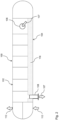
Figure 2 schematically shows a heat exchanger, which can be used to implement the present invention. -
Figure 3 schematically shows a connecting piece and a drain line section at the bottom side of a heat exchanger in an exploded view inFigure 3 A , and in the assembled state inFigure 3 B . - The embodiments according to the figures are discussed comprehensively, same reference signs designate same or structurally identical elements.
-
Figure 1 schematically shows a detail of an embodiment of aheat exchanger 100 according to the present invention. - The
heat exchanger 100 comprises a connectingpiece 128 at abottom side 104 of theheat exchanger 100, as will be further explained below in connection withFigure 2 . The connectingpiece 128 connects the inside of theheat exchanger 100 with an outside of theheat exchanger 100, particularily with the outside of theheat exchanger shell 101. The connectingpiece 128 further comprises adrain line section 124, which protrudes into the inside of theheat exchanger 100 and which has at least one drain opening 125. In the embodiment shown, the at least one drain opening 125 is the upper open end of thedrain line section 124. By means of this construction, thedrain line section 124 is configured as an overflow for anyfluid 116 accumulated inside the heat exchanger up to a retaining height h defined by thedrain opening 125. As soon as the accumulated fluid reaches the position of the drain opening 125 defining the retaining height, the fluid drains through thedrain line section 124 to the outside of theheat exchanger 100. The retaining height h is defined by the vertical distance of thedrain opening 125 to the inner surface at thebottom side 104 of theheat exchanger 100 in the configuration of the embodiments shown in the present figures. It goes without saying that depending on the draining capacity of thedrain line section 124, the actual retaining height might be larger than the retaining height h defined by the position of the drain opening. - The connecting
piece 128 may be a connecting piece specially provided for its configuration as an overflow according to the present invention, but may also be an existing inlet/outlet socket for an inlet/outlet pipe conducting a heat exchanging fluid into or out of the inside of theheat exchanger 100 as far as this inlet/outlet socket is not connected to tubes in the interior of the heat exchanger. This can be advantageous, for example, for the inlet nozzle/socket of a steam drum. In this case, condensate would be prevented from immediately flowing back into the inlet gas (steam) connection coming from below. - As shown in
Figure 2 , aheat exchanger 100, in the present case a tubular heat exchanger, comprises inlet and outlet sockets for conducting heat exchanging fluids through the inside of theheat exchanger 100. As shown inFigure 2 , a firstheat exchanging fluid 107 is conducted throughinlet socket 106 into the inside of theheat exchanger 100 for transferring heat to a secondheat exchanging fluid 112 introduced into theheat exchanger 100 at a lower temperature level. After the heat exchanging process, thefirst fluid 107 leaves theheat exchanger 100 through anoutlet socket 108, while thesecond fluid 112, which was introduced at a bottom side in the head of theheat exchanger 100, leaves theheat exchanger 100 through an outlet socket at the top of theheat exchanger 100 as shown inFigure 2 . The top side of theheat exchanger 100, in operation, is designated 102, while the bottom side of theheat exchanger 100, in operation, is designated 104. - The
heat exchanger 100 ofFigure 2 may be used as a condenser, wherein condensate accumulates in the interior of the heat exchanger at its bottom side. The accumulated fluid or condesate is designated 116. In order to subcool the condensate it is necessary to accumulate the condensate up to a certain retaining height where the condensate covers a predefined number of heat exchanger tubes. Excess condensate should be drained in order not to impede the condensation process. The present invention provides anoverflow 120 for such condensate when the accumulated condensate reaches a predetermined retaining height (h). As can be seen fromFigure 2 , the existingoutlet socket 108 for the firstheat exchanging fluid 107 can be used for such an overflow, an embodiment of which is shown asoverflow 120 inFigure 1 discussed above. - Returning to
Figure 1 , theoverflow 120 may comprise theoutlet socket 108 of the heat exchanger shown in Firgure 2 as the connectingpiece 128. Further, theoverflow 120 comprises adrain line section 124, which, at least partially, has the form of a sleeve, which is inserted into the connectingpiece 128. Sleeve and connecting piece are coaxial to each other. Thedrain line section 124 or sleeve further comprises a sealingflange 126 to provide a sealed connection with the connectingpiece 128. In a further embodiment, the sealingflange 126 comprises a fastening means for detachably connecting thesleeve 124 and the connectingpiece 128. By such a construction, an existing inlet/outlet socket 108 of theheat exchanger 100 may be retrofitted to comprise anoverflow 120 according to the present invention. While theoutlet socket heat exchanging fluid 107 out of theheat exchanger 100, at the same time, theoutlet socket condensate overflow 120. In an alternative embodiment, the sleeve ordrain line section 124 is welded to the connecting piece. -
Figure 3 schematically shows an exploded view of an embodiment of a detail of aheat exchanger 100 according the present invention. In the embodiment ofFigure 3 , the connectingpiece 128 comprises different elements, namely anozzle neck 128a with aflange 128b followed by apiping flange 128c. Again, the connectingpiece 128 may be the existingoutlet socket 108 of aheat exchanger 100 as shown inFigure 2 . In order to implement the overflow function according to present invention, adrain line section 124 is inserted into the connectingpiece drain line section 124 is formed as a sleeve, the outer diameter of which essentially corresponds to the inner diameter of the connectingpiece drain line section 124 forms a collar, which abuts against theflange 128b in the assembled state. In the embodiment ofFigure 3 , a sealed connection between thedrain line section 124 and the connectingpiece 128 is created by means ofgaskets 127. In the embodiment ofFigure 3 , it is possible to realize different retaining heights h by usingdrain line sections 124 of different sleeve lengths.Figure 3B shows theoverflow 120 ofFigure 3A in an assembled state.
Claims (8)
- A heat exchanger (100) for exchanging heat between heat exchanging fluids (107,112) conducted through an inside of the heat exchanger (100), the heat exchanger (100) comprising a connecting piece (108,128) at a bottom side (104) of the heat exchanger (100), the connecting piece (108,128) connecting the inside of the heat exchanger (100) with an outside of the heat exchanger (100), the connecting piece (108,128) comprising a drain line section (124) protruding into the inside of the heat exchanger (100) and having at least one drain opening (125), the drain line section (124) being configured as an overflow for any fluid (116) accumulated inside the heat exchanger up to a retaining height (h) defined by the at least one drain opening (125).
- The heat exchanger (100) of claim 1, wherein the connecting piece (108,128) is a connecting piece of an inlet pipe of the heat exchanger (100) for conducting one of the heat exchanging fluids (107,112) into the inside of the heat exchanger (100) or a connecting piece (108) of an outlet pipe of the heat exchanger (100) for conducting one of the heat exchanging fluids (107) to the outside of the heat exchanger (100).
- The heat exchanger (100) of claim 1 or 2, wherein the drain line section (124), at least partially, has the form of a sleeve, which is inserted into the connecting piece (108,128).
- The heat exchanger (100) of claim 3, wherein the sleeve is configured to be moveable inside the connecting piece (108,128) to adjust the retaining height (h).
- The heat exchanger (100) of any one of the preceding claims, wherein the drain line section (124) comprises a sealing flange (126) configured to provide a sealed connection with the connecting piece (108,128).
- The heat exchanger (100) of claim 5, when referring back to claim 4 or 3,
wherein the sealing flange (126) comprises a fastening means for detachably connecting the sleeve and the connecting piece (108,128). - The heat exchanger (100) according to any one of the preceding claims,
wherein the drain line section (124) is an integral part of the connecting piece (108,128). - Use of the heat exchanger (100) according to any one of the claims 1 to 7 for retaining a condensate as the accumulated fluid (116) inside the heat exchanger (100) up to a retaining height (h) defined by the at least one drain opening (125) of the drain line section (124) protruding into the inside of the heat exchanger (100).
Priority Applications (1)
| Application Number | Priority Date | Filing Date | Title |
|---|---|---|---|
| EP24020003.0A EP4582763A1 (en) | 2024-01-04 | 2024-01-04 | Heat exchanger and use thereof |
Applications Claiming Priority (1)
| Application Number | Priority Date | Filing Date | Title |
|---|---|---|---|
| EP24020003.0A EP4582763A1 (en) | 2024-01-04 | 2024-01-04 | Heat exchanger and use thereof |
Publications (1)
| Publication Number | Publication Date |
|---|---|
| EP4582763A1 true EP4582763A1 (en) | 2025-07-09 |
Family
ID=89473921
Family Applications (1)
| Application Number | Title | Priority Date | Filing Date |
|---|---|---|---|
| EP24020003.0A Pending EP4582763A1 (en) | 2024-01-04 | 2024-01-04 | Heat exchanger and use thereof |
Country Status (1)
| Country | Link |
|---|---|
| EP (1) | EP4582763A1 (en) |
Citations (4)
| Publication number | Priority date | Publication date | Assignee | Title |
|---|---|---|---|---|
| US4057103A (en) * | 1974-12-10 | 1977-11-08 | Kraftwerk Union Aktiengesellschaft | Feedwater preheater with two steam chambers |
| US6095238A (en) * | 1997-11-26 | 2000-08-01 | Kabushiki Kaisha Toshiba | Feed water heater |
| US8528503B2 (en) * | 2009-02-27 | 2013-09-10 | Advanced Steam Technology | Heat exchange system and method |
| EP3187708B1 (en) * | 2014-08-27 | 2018-10-17 | Toyota Jidosha Kabushiki Kaisha | Intercooler device for supercharged internal combustion engine |
-
2024
- 2024-01-04 EP EP24020003.0A patent/EP4582763A1/en active Pending
Patent Citations (4)
| Publication number | Priority date | Publication date | Assignee | Title |
|---|---|---|---|---|
| US4057103A (en) * | 1974-12-10 | 1977-11-08 | Kraftwerk Union Aktiengesellschaft | Feedwater preheater with two steam chambers |
| US6095238A (en) * | 1997-11-26 | 2000-08-01 | Kabushiki Kaisha Toshiba | Feed water heater |
| US8528503B2 (en) * | 2009-02-27 | 2013-09-10 | Advanced Steam Technology | Heat exchange system and method |
| EP3187708B1 (en) * | 2014-08-27 | 2018-10-17 | Toyota Jidosha Kabushiki Kaisha | Intercooler device for supercharged internal combustion engine |
Similar Documents
| Publication | Publication Date | Title |
|---|---|---|
| US8056553B2 (en) | Condensate pan with condensate trap | |
| US6729386B1 (en) | Pulp drier coil with improved header | |
| EP2241848A2 (en) | Heat exchanger | |
| US4121656A (en) | Header | |
| CN103261827A (en) | Heat exchanger | |
| US7377307B1 (en) | Vertical heat exchanger | |
| US4558734A (en) | Heat exchanger having a set of pipes | |
| EP2965022B1 (en) | Fired heat exchanger | |
| JP2007010298A (en) | Heat exchanger with receiver tank | |
| CN113028629B (en) | Condensate water drainage device and air conditioner | |
| RU184379U1 (en) | AIR COOLED CONDENSER | |
| US20210310697A1 (en) | Condensate trap for gas furnace | |
| JPH109776A (en) | Heat exchanger | |
| CN110094996A (en) | A kind of heat exchanger applied to paper making equipment | |
| CN214199785U (en) | Double-water synchronous circulating shell-and-tube heat exchanger | |
| AU654536B2 (en) | High-pressure feedwater preheater | |
| US20070068660A1 (en) | Heat exchanging unit for motor vehicles | |
| US20240426478A1 (en) | Condensing heat exchanger and gas device | |
| TWI916248B (en) | Cold trap device | |
| US11047596B1 (en) | High temperature fluid generator | |
| KR101994232B1 (en) | Heat exchanger for boiler | |
| CN208012065U (en) | A kind of condensing gas-fired fast water heater | |
| CN217356055U (en) | Water seal assembly | |
| KR100202850B1 (en) | Full drain type heating and cooling coil | |
| CN222048675U (en) | Heat exchanger exhaust hole and heat exchanger |
Legal Events
| Date | Code | Title | Description |
|---|---|---|---|
| PUAI | Public reference made under article 153(3) epc to a published international application that has entered the european phase |
Free format text: ORIGINAL CODE: 0009012 |
|
| STAA | Information on the status of an ep patent application or granted ep patent |
Free format text: STATUS: THE APPLICATION HAS BEEN PUBLISHED |
|
| AK | Designated contracting states |
Kind code of ref document: A1 Designated state(s): AL AT BE BG CH CY CZ DE DK EE ES FI FR GB GR HR HU IE IS IT LI LT LU LV MC ME MK MT NL NO PL PT RO RS SE SI SK SM TR |
|
| STAA | Information on the status of an ep patent application or granted ep patent |
Free format text: STATUS: REQUEST FOR EXAMINATION WAS MADE |
|
| 17P | Request for examination filed |
Effective date: 20260108 |