EP4582756A1 - Refrigerator - Google Patents
Refrigerator Download PDFInfo
- Publication number
- EP4582756A1 EP4582756A1 EP23867046.7A EP23867046A EP4582756A1 EP 4582756 A1 EP4582756 A1 EP 4582756A1 EP 23867046 A EP23867046 A EP 23867046A EP 4582756 A1 EP4582756 A1 EP 4582756A1
- Authority
- EP
- European Patent Office
- Prior art keywords
- door body
- fixing
- connecting rod
- disposed
- sliding member
- Prior art date
- Legal status (The legal status is an assumption and is not a legal conclusion. Google has not performed a legal analysis and makes no representation as to the accuracy of the status listed.)
- Pending
Links
Images




Classifications
-
- F—MECHANICAL ENGINEERING; LIGHTING; HEATING; WEAPONS; BLASTING
- F25—REFRIGERATION OR COOLING; COMBINED HEATING AND REFRIGERATION SYSTEMS; HEAT PUMP SYSTEMS; MANUFACTURE OR STORAGE OF ICE; LIQUEFACTION SOLIDIFICATION OF GASES
- F25D—REFRIGERATORS; COLD ROOMS; ICE-BOXES; COOLING OR FREEZING APPARATUS NOT OTHERWISE PROVIDED FOR
- F25D23/00—General constructional features
- F25D23/02—Doors; Covers
- F25D23/028—Details
-
- E—FIXED CONSTRUCTIONS
- E05—LOCKS; KEYS; WINDOW OR DOOR FITTINGS; SAFES
- E05F—DEVICES FOR MOVING WINGS INTO OPEN OR CLOSED POSITION; CHECKS FOR WINGS; WING FITTINGS NOT OTHERWISE PROVIDED FOR, CONCERNED WITH THE FUNCTIONING OF THE WING
- E05F15/00—Power-operated mechanisms for wings
- E05F15/60—Power-operated mechanisms for wings using electrical actuators
- E05F15/603—Power-operated mechanisms for wings using electrical actuators using rotary electromotors
- E05F15/611—Power-operated mechanisms for wings using electrical actuators using rotary electromotors for swinging wings
- E05F15/63—Power-operated mechanisms for wings using electrical actuators using rotary electromotors for swinging wings operated by swinging arms
-
- E—FIXED CONSTRUCTIONS
- E05—LOCKS; KEYS; WINDOW OR DOOR FITTINGS; SAFES
- E05Y—INDEXING SCHEME ASSOCIATED WITH SUBCLASSES E05D AND E05F, RELATING TO CONSTRUCTION ELEMENTS, ELECTRIC CONTROL, POWER SUPPLY, POWER SIGNAL OR TRANSMISSION, USER INTERFACES, MOUNTING OR COUPLING, DETAILS, ACCESSORIES, AUXILIARY OPERATIONS NOT OTHERWISE PROVIDED FOR, APPLICATION THEREOF
- E05Y2201/00—Constructional elements; Accessories therefor
- E05Y2201/60—Suspension or transmission members; Accessories therefor
- E05Y2201/622—Suspension or transmission members elements
- E05Y2201/624—Arms
-
- E—FIXED CONSTRUCTIONS
- E05—LOCKS; KEYS; WINDOW OR DOOR FITTINGS; SAFES
- E05Y—INDEXING SCHEME ASSOCIATED WITH SUBCLASSES E05D AND E05F, RELATING TO CONSTRUCTION ELEMENTS, ELECTRIC CONTROL, POWER SUPPLY, POWER SIGNAL OR TRANSMISSION, USER INTERFACES, MOUNTING OR COUPLING, DETAILS, ACCESSORIES, AUXILIARY OPERATIONS NOT OTHERWISE PROVIDED FOR, APPLICATION THEREOF
- E05Y2201/00—Constructional elements; Accessories therefor
- E05Y2201/60—Suspension or transmission members; Accessories therefor
- E05Y2201/622—Suspension or transmission members elements
- E05Y2201/71—Toothed gearing
-
- E—FIXED CONSTRUCTIONS
- E05—LOCKS; KEYS; WINDOW OR DOOR FITTINGS; SAFES
- E05Y—INDEXING SCHEME ASSOCIATED WITH SUBCLASSES E05D AND E05F, RELATING TO CONSTRUCTION ELEMENTS, ELECTRIC CONTROL, POWER SUPPLY, POWER SIGNAL OR TRANSMISSION, USER INTERFACES, MOUNTING OR COUPLING, DETAILS, ACCESSORIES, AUXILIARY OPERATIONS NOT OTHERWISE PROVIDED FOR, APPLICATION THEREOF
- E05Y2201/00—Constructional elements; Accessories therefor
- E05Y2201/60—Suspension or transmission members; Accessories therefor
- E05Y2201/622—Suspension or transmission members elements
- E05Y2201/71—Toothed gearing
- E05Y2201/712—Toothed gearing with incomplete toothing
-
- E—FIXED CONSTRUCTIONS
- E05—LOCKS; KEYS; WINDOW OR DOOR FITTINGS; SAFES
- E05Y—INDEXING SCHEME ASSOCIATED WITH SUBCLASSES E05D AND E05F, RELATING TO CONSTRUCTION ELEMENTS, ELECTRIC CONTROL, POWER SUPPLY, POWER SIGNAL OR TRANSMISSION, USER INTERFACES, MOUNTING OR COUPLING, DETAILS, ACCESSORIES, AUXILIARY OPERATIONS NOT OTHERWISE PROVIDED FOR, APPLICATION THEREOF
- E05Y2900/00—Application of doors, windows, wings or fittings thereof
- E05Y2900/30—Application of doors, windows, wings or fittings thereof for domestic appliances
-
- E—FIXED CONSTRUCTIONS
- E05—LOCKS; KEYS; WINDOW OR DOOR FITTINGS; SAFES
- E05Y—INDEXING SCHEME ASSOCIATED WITH SUBCLASSES E05D AND E05F, RELATING TO CONSTRUCTION ELEMENTS, ELECTRIC CONTROL, POWER SUPPLY, POWER SIGNAL OR TRANSMISSION, USER INTERFACES, MOUNTING OR COUPLING, DETAILS, ACCESSORIES, AUXILIARY OPERATIONS NOT OTHERWISE PROVIDED FOR, APPLICATION THEREOF
- E05Y2900/00—Application of doors, windows, wings or fittings thereof
- E05Y2900/30—Application of doors, windows, wings or fittings thereof for domestic appliances
- E05Y2900/31—Application of doors, windows, wings or fittings thereof for domestic appliances for refrigerators
Definitions
- the invention belongs to a technical field of electrical apparatus, and in particular relates to a refrigerator.
- the invention intends to at least to a certain extent solve a technical problem that a displacement of a door body affects a door opening and closing device. To this end, the invention provides a refrigerator.
- a refrigerator which comprises: a main body formed with an accommodation space which has an opening; a door body rotatably disposed on the main body via a rotating shaft to close or open the opening; a door opening and closing device disposed on the main body and connected to the door body, wherein when the door opening and closing device is activated, the door opening and closing device drives the door body to rotate relative to the main body to open or close the door body, the door opening and closing device comprising a front connecting rod; and a sliding assembly comprising a connecting member and a sliding member, wherein the connecting member is fixed to one of the front connecting rod and the door body, the sliding member being disposed on another of the front connecting rod and the door body, the sliding member being movably connected to the connecting member, and thus the front connecting rod is able to move along an axial direction of the rotating shaft relative to the door body.
- the terms “connected”, “fixed” and so on should be understood in a broad sense.
- “fixed” can be a fixed connection, a detachable connection, or an integral connection; it can be a mechanical connection or an electrical connection; it can be a direct connection or an indirect connection through an intermediate medium; it can be an internal connection of two elements or an interaction relationship between two elements, unless otherwise clearly limited.
- “fixed” can be a fixed connection, a detachable connection, or an integral connection; it can be a mechanical connection or an electrical connection; it can be a direct connection or an indirect connection through an intermediate medium; it can be an internal connection of two elements or an interaction relationship between two elements, unless otherwise clearly limited.
- the specific meanings of the above terms in the embodiments of the invention can be understood according to specific circumstances.
- a traditional door opening and closing device cannot be applied to double-door refrigerators.
- the traditional door opening and closing device when used in cross-door refrigerators and other multi-door refrigerators, also needs additional protection during transportation and circulation.
- the door body of the refrigerators is prone to be displaced up and down during transportation and circulation.
- the double-door refrigerator has a special door self-locking structure, and thus the door body will inevitably move up and down in the process of opening and closing the door body. That is to say, the door body, when being opened and closed, will be displaced up and down, to cause a situation that the door opening and closing device gets stuck in movement or gets damage to components of the door opening and closing device due to an up and down displacement of the door body.
- FIG. 1 shows a schematic structural diagram of a refrigerator with an opened door body according to some embodiments of the invention
- FIG. 2 shows a schematic structural diagram of the refrigerator with a closed door body according to some embodiments of the invention.
- a refrigerator 10 is provided according to some embodiments of the invention.
- the refrigerator 10 can minimize an impact of a displacement of the door body 13 on a door opening and closing device 11, to increase a service life of the door opening and closing device 11.
- the transmission mechanism 300 may be a linkage gear.
- the linkage gear is in transmission connection with the driving mechanism 100.
- the door rotation mechanism 400 is connected to the linkage gear.
- the driving mechanism 100 drives, through the linkage gear, the door rotation mechanism 400 to rotate to realize a function of door opening and closing.
- the linkage gear can also be connected to a door ejection member and a suspension mechanism. Functions of door ejection, door rotation and suspension can be realized through one linkage gear, to be capable of reducing the number of components of the door opening and closing device 11 and improving an integration of the entire door opening and closing device 11.
- the transmission mechanism 300 in addition to being a linkage gear, can also be an ordinary transmission gear in some embodiments.
- the function of door opening and closing can also be realized in the way that the transmission gear drives the door rotation mechanism 400 to rotate.
- the transmission mechanism 300 may also be chain-driven or belt-driven to drive the door rotation mechanism 400 to rotate, to realize the function of door opening and closing through the door rotation mechanism 400.
- transmission mechanism 300 that can be connected to the driving mechanism 100 and can drive the door rotation mechanism 400 to rotate are all within a scope sought by the invention.
- FIG. 3 is a schematic structural diagram showing a connection way between a front connecting rod and a door body of the refrigerator according to some embodiments of the invention; and FIG. 4 shows an exploded view of the front connecting rod and the door body of the refrigerator of FIG. 3 .
- the refrigerator 10 may also comprise a sliding assembly 500 which comprises a connecting member 520 and a sliding member 510.
- the connecting member 520 is fixed to one of the front connecting rod 410 and the door body 13.
- the sliding member 510 is disposed on another of the front connecting rod 410 and the door body 13.
- the sliding member 510 is movably connected to the connecting member 520, to enable the front connecting rod 410 to move relative to the door body 13 along an axial direction of the rotating shaft 16.
- the driving mechanism 100 After the driving mechanism 100 receives a door opening signal, the driving mechanism 100 is activated to rotate forward, to drive the transmission mechanism 300 to rotate.
- the transmission mechanism 300 drives the door rotation mechanism 400 to rotate, to open the door body 13.
- the driving mechanism 100 After the driving mechanism 100 receives a door closing signal, the driving mechanism 100 is activated to rotate reversely, to drive the transmission mechanism 300 to rotate in an opposite direction, and thus the transmission mechanism 300 drives the door rotation mechanism 400 to rotate in the opposite direction to close the door body 13.
- one of the connecting member 520 and the sliding member 510 is connected to the front connecting rod 410, and another of the connecting member 520 and the sliding member 510 is connected to the door body 13
- the sliding member 510 and the connecting member 520 are movably connected.
- the door body 13 When the door body 13 is displaced up and down, the door body 13 can slide up and down relative to the sliding member 510, to be capable of reducing a noise generated by a displacement of the refrigerator 10 during transportation, and avoiding a risk of the door opening and closing device 11 being stuck in movement and unable to open and close the door body normally.
- a normal operation of the door opening and closing device 11 can be ensured, and a damage to components of the door opening and closing device 11 can also be reduced, to increase a service life of the entire door opening and closing device 11.
- the front connecting rod 410 may not be moved up and down with the door body 13, to be capable of reducing a risk of deformation of the front connecting rod 410 caused by an up and down displacement of the door body 13.
- a service life of the front connecting rod 410 can be improved, to improve the service life of the entire door opening and closing device 11.
- a fixing member 530 is disposed on the door body 13.
- the connecting member 520 is connected to the fixing member 530.
- the sliding member 510 is connected to the front connecting rod 410 and is slidably sleeved on the connecting member 520, to enable the front connecting rod 410 to move along an axial direction of the rotating shaft 16 relative to the connecting member 520.
- the sliding member 510 is slidably sleeved on the connecting member 520.
- the connecting member 520 is connected to the fixing member 530.
- the sliding member 510 can slide relative to the connecting member 520, that is, when the door body 13 is displaced up and down, the door body 13 can slide up and down relative to the sliding member 510, while the front connecting rod 410 may not be displaced up and down with the door body 13, to be capable of reducing a noise generated by a displacement of the refrigerator 10 during transportation, and avoiding a risk of the door opening and closing device 11 being stuck in movement and unable to open and close the door body normally.
- the up and down displacement of the door body 13 refers to a movement along an extension direction of the rotation shaft 16.
- the fixing member 530 is fixedly disposed on the door body 13, and the connecting member 520 is fixedly connected to the fixing member 530, that is, the door body 13, the fixing member 530 and the connecting member 520 are connected as a whole.
- the fixing member 530 and the connecting member 520 will be driven to be displaced up and down with the door body 13.
- the sliding member 510 can slide relative to the connecting member 520, and thus the up and down displacement of the door body 13 will not be transmitted to the front connecting rod 410 and will not affect a normal operation of the door opening and closing device 11, to improve the service life of the entire door opening and closing device 11.
- the fixing member 530 and the connecting member 520 are displaced up and down along with the door body 13, to cause the connecting member 520 to slide relative to the sliding member 510.
- the sliding member 510 is stationary and the connecting member 520 moves, to realize a sliding of the connecting member 520 relative to the sliding member 510.
- the transition portion 537 is connected to the first limiting portion 534, and another end of the transition portion 537 is connected to the second connecting portion 532.
- the first limiting portion 534 is fixedly connected to the door body 13, to fix the entire fixing member 530 on the door body 13.
- the first limiting portion 534 is fixedly connected to the bottom wall of the installation groove 15. It is suitable for a structure in which a thickness of the door body 13 is relatively large. The door body 13 can be prevented from being pierced by screws to be damaged.
- the above is only one implementation way of the fixing member 530 and the connecting member 520.
- the fixing member 530 and the connecting member 520 may have other implementation ways and ways for fixing to the door body 13.
- FIG. 5 is a schematic structural diagram showing a connection way between a front connecting rod and a door body of the refrigerator according to some embodiments of the invention
- FIG. 6 shows an exploded view of the front connecting rod and the door body of the refrigerator of FIG. 5
- the fixing member 530 may further comprise an installation portion 538.
- the transition portion 537 connects the first limiting portion 534 and the second limiting portion 535.
- the installation portion 538 is connected to the transition portion 537 and is connected to the door body 13.
- the installation portion 538 is connected to the door body 13, to be capable of reducing connection positions between the entire fixing member 530 and the door body 13, and thus the first limiting portion 534 and the second limiting portion 535 only play a role of limiting.
- transition portion 537, the first limiting portion 534, and the second limiting portion 535 are disposed in the installation groove 15.
- FIG. 7 is a schematic structural diagram showing a connection way between a front connecting rod and a door body of the refrigerator according to some embodiments of the invention; and FIG. 8 shows an exploded view of the front connecting rod and the door body of the refrigerator of FIG. 7.
- FIGs. 7 and 8 show another implementation way of the fixing member 530 and the connecting member 520.
- the fixing member 530 comprises a fixing portion 531 and a connecting portion 532 that are connected to each other.
- the connecting portion 532 is connected to the door body 13.
- the connecting member 520 comprises a connecting shaft 521 and an end cover 523.
- the end cover 523 is disposed at an end of the connecting shaft 521.
- the sliding member 510 is sleeved on the connecting shaft 521, so that the front connecting rod 410 can slide between the fixing portion 531 and the end cover 523.
- the fixing portion 531 and the connecting portion 532 are connected to each other.
- An end of the connecting shaft 521 is connected to the fixing portion 531, and another end of the connecting shaft 521 is connected to the end cover 523.
- the sliding member 510 can slide between the fixing portion 531 and the end cover 523.
- the fixing portion 531 and the end cover 523 play a role of limiting to prevent the sliding member 510 from falling off the connecting shaft 521.
- An extension direction of the connecting shaft 521 is the same as the extension direction of the rotating shaft 16.
- the sliding member 510 can drive the front connecting rod 410 to directly slide relative to the door body 13 along the extension direction of the rotating shaft 16, to avoid the front connecting rod 410 from being unable to open or close the door body 13 normally due to a deformation of the front connecting rod 410 caused by the displacement of the door body 13.
- the connecting shaft 521 and the end cover 523 are integrally formed.
- the entire connecting member 520 is substantially T-shaped, and the fixing portion 531 is disposed at another end of the connecting shaft 521, and thus the connecting member 520 and the fixing portion 531 are substantially I-shaped.
- a connecting hole 533 is disposed on the fixing portion 531. An end of the connecting shaft 521 away from the end cover 523 is installed in the connecting hole 533.
- a sliding member 510 is disposed between the connecting hole 533 and the connecting shaft 521. The connecting hole 533 is engaged into a fixing slot 515 of the sliding member 510. The sliding member 510 is sleeved on an end of the connecting shaft 521 away from the end cover 523. If the connecting shaft 521 moves relative to the fixing portion 531 along the direction of the rotating shaft 16, the connecting shaft 521 can move relative to the connecting hole 533, to prevent the front connecting rod 410 from moving and reduce a deformation of the front connecting rod 410.
- the fixing member 530 and the connecting member 520 are disposed in the installation groove 15.
- the end cover 523 contacts the bottom wall of the installation groove 15.
- the connecting portion 532 is fixedly connected to the side wall of the installation groove 15.
- the end cover 523 is installed on the bottom wall of the installation groove 15, to be capable of avoiding the connecting shaft 521 from falling out of the connecting hole 533.
- the connecting portion 532 is fixedly connected to the side wall of the installation groove 15, that is, the connecting member 520 and fixing member 530 are both disposed in the installation groove 15.
- the connecting portion 532 is connected to the door body 13 in a thickness direction of the door body 13.
- the fixing portion 531 and the connecting portion 532 are connected at an angle.
- the end cover 523 is disposed on the bottom wall of the installation groove 15.
- the end cover 523 and the fixing portion 531 are respectively disposed at two ends of the connecting shaft 521, that is, the end cover 523 and the fixing portion 531 are oppositely disposed.
- the fixing portion 531 is disposed close to the opening of the installation groove 15.
- the connecting portion 532 is connected to the side wall of the installation groove 15. In order to reduce connections between the fixing portion 531 to the connecting shaft 521, the connecting portion 532 is connected to the side wall of the installation groove 15, and thus the fixing portion 531 and the connecting portion 532 are required to be disposed at an angle.
- the connecting portion 532 and the side wall of the installation groove 15 are connected by screws.
- a connection by screw is convenient and simple and easy to operate.
- the connecting member 520 is disposed on the front connecting rod 410.
- the connecting member 520 is disposed in the installation hole 514.
- the connecting member 520 can be rotated relative to the installation hole 514.
- the transmission mechanism 300 drives the door rotation mechanism 400 to rotate, and the front connecting rod 410, through the connecting member 520, drives the door body 13 to rotate, to open the door body 13.
- a fixing hole 14 is disposed on the door body 13.
- the sliding member 510 is sleeved on the front connecting rod 410 and installed in the fixing hole 14. In a condition that the door opening and closing device 11 opens or closes the door body 13, if the door body 13 is displaced up and down, the sliding member 510 can move relative to the fixing hole 14 along an axial direction of the rotating shaft 16, that is, when the door body 13 is displaced up and down, the door body 13 can slide up and down relative to the sliding member 510, and the front connecting rod 410 will not be displaced up and down with the door body 13. Thus an adaptability, reliability and usage experience of the door body 13 can be improved.
- the up and down displacement of the door body 13 refers to a movement along an extension direction of the rotation shaft 16.
- the fixing hole 14 is disposed above the door body 13, that is, disposed on an upper surface of the door body 13.
- the front connecting rod 410 is connected to the sliding member 510.
- the sliding member 510 is disposed in the fixing hole 14.
- the front connecting rod 410 is disposed above the door body 13, and from above the door body 13 drives the door body 13 to rotate.
- the fixing hole 14 has a fixing surface 14d.
- a stop surface 511 is provided on the sliding member 510.
- the fixing surface 14d cooperates with the stop surface 511.
- a shape of the fixing surface 14d is different from a shape of the fixing hole 14, and a shape of the stop surface 511 is different from a shape of the sliding member 510.
- the shape of the fixing surface 14d being different from the shape of the fixing hole 14 indicates that the shape of the fixing surface 14d is different from a shape of a hole wall of the fixing hole 14.
- the shape of the stop surface 511 being different from the shape of the sliding member 510 indicates that the shape of the stop surface 511 is different from a contour of the sliding member 510.
- the shape of the fixing surface 14d is different from that of the fixing hole 14, and the shape of the stop surface 511 is different from that of the sliding member 510.
- the shape of the stop surface 511 matches the shape of the fixing surface 14d, which indicates that the shapes of the stop surface 511 and the fixing surface 14d are the same.
- the fixing surface 14d is a plane
- the stop surface 511 is also a plane. If the fixing surface 14d is a curved surface, the stop surface 511 is also a curved surface, as long as the two can be matched.
- the fixing surface 14d is disposed on the fixing hole 14.
- the shape of the fixing surface 14d being different from the shape of the fixing hole 14 indicates that the shape of the fixing surface 14d is different from shapes of other portions of the fixing hole 14.
- the stop surface 511 is disposed on the sliding member 510.
- the shape of the stop surface 511 being different from the shape of the sliding member 510 indicates that the shape of the stop surface 511 is different from shapes of other portions of the sliding member 510.
- the sliding member 510 is cylindrical.
- the stop surface 511 is disposed on a peripheral wall of the sliding member 510, that is, the sliding member 510 is an incomplete cylinder, and is a cylinder with a notch.
- the fixing hole 14 is circular, the stop surface 511 is disposed on the hole wall of the fixing hole 14, and the fixing hole 14 is circular with a notch.
- the fixing hole 14 comprises a fixing section 14b and a connecting section 14c that are interconnected.
- the sliding member 510 comprises a stop section and an installation section 513 that are interconnected.
- the installation section is disposed close to the front connecting rod 410.
- the fixing section 14b cooperates with the stop section.
- the connecting section 14c cooperates with the installation section.
- the fixing surface 14d is disposed on the fixing section 14b.
- the stop surface 511 is disposed on the stop section.
- the installation section is disposed close to the front connecting rod 410.
- the fixing section 14 b is disposed close to a bottom of the fixing hole 14, and the stop surface 511 is disposed at a lower portion, to facilitate an installation of the sliding member 510 and reduce a difficulty in installing the sliding member 510 to the fixing hole 14.
- the fixing hole 14 is circular.
- a diameter of the fixing section 14b is smaller than a diameter of the connecting section 14c.
- the sliding member 510 is cylindrical.
- a diameter of the stop section is smaller than a diameter of the installation section.
- the diameter of the fixing section 14b is smaller than the diameter of the connecting section 14c.
- the diameter of the stop section is smaller than the diameter of the installation section. Since the fixing surface 14d is disposed on the fixing section 14b, the fixing section 14b is not a complete cylinder.
- the fixing section 14b and the connecting section 14c are concentrically disposed.
- a diameter of the fixing section 14b refers to twice a radius of an arc portion of the fixing section 14b.
- the stop surface 511 is disposed on the stop section, and thus the stop surface 511 is also not a complete cylinder.
- the stop section and the installation section are concentrically disposed.
- a diameter of the stop section refers to twice a radius of an arc portion of the stop section.
- one of the connecting member 520 and the sliding member 510 is connected to the front connecting rod 410, and another of the connecting member 520 and the sliding member 510 is connected to the door body 13.
- the sliding member 510 and the connecting member 520 are slidably connected.
- the door body 13 can slide up and down relative to the sliding member 510, while the front connecting rod 410 will not be displaced up and down with the door body 13.
- a risk of deformation of the front connecting rod 410 due to the up and down displacement of the door body 13 can be reduced.
- a situation in which the door opening and closing device 11 gets stuck in movement due to the up and down displacement of the door body 13 can be reduced to a certain extent.
Landscapes
- Engineering & Computer Science (AREA)
- Chemical & Material Sciences (AREA)
- Combustion & Propulsion (AREA)
- Physics & Mathematics (AREA)
- Mechanical Engineering (AREA)
- Thermal Sciences (AREA)
- General Engineering & Computer Science (AREA)
- Refrigerator Housings (AREA)
- Power-Operated Mechanisms For Wings (AREA)
Abstract
Description
- This application claims priority to
Chinese patent application No. 202211145486.9, filed on September 20, 2022 - The invention belongs to a technical field of electrical apparatus, and in particular relates to a refrigerator.
- With the improvement of living standards, electrical apparatuses such as refrigerators, dishwashers and disinfection cabinets have become widely used in lives of people. In particular, in order to maintain a sealing performance of the refrigerator, an adsorption structure is usually disposed between a main body and a door body thereof or negative pressure is maintained within the main body, to stably fix the door body to the main body. Although a related performance of the refrigerator is improved in this way, a difficulty of opening the door body is also increased to a certain extent. Since a larger force is usually required to open the door body of the refrigerator, it is inconvenient to use. In order to overcome the above problems, a door opening and closing device is used in the related art to open or close the door body. During the door body is opened or closed by the door opening and closing device, the door body is prone to be displaced up and down, resulting in a damage to the door opening and closing device.
- The invention intends to at least to a certain extent solve a technical problem that a displacement of a door body affects a door opening and closing device. To this end, the invention provides a refrigerator.
- According to some embodiments of the invention, a refrigerator is provided, which comprises: a main body formed with an accommodation space which has an opening; a door body rotatably disposed on the main body via a rotating shaft to close or open the opening; a door opening and closing device disposed on the main body and connected to the door body, wherein when the door opening and closing device is activated, the door opening and closing device drives the door body to rotate relative to the main body to open or close the door body, the door opening and closing device comprising a front connecting rod; and a sliding assembly comprising a connecting member and a sliding member, wherein the connecting member is fixed to one of the front connecting rod and the door body, the sliding member being disposed on another of the front connecting rod and the door body, the sliding member being movably connected to the connecting member, and thus the front connecting rod is able to move along an axial direction of the rotating shaft relative to the door body.
- In order to more clearly illustrate the technical solutions in the embodiments of the invention, the accompanying drawings required for describing the embodiments are briefly introduced below. Obviously, the accompanying drawings in the following description only illustrate some embodiments of the invention, and for those skilled in the art, other accompanying drawings can also be obtained based on these accompanying drawings without creative efforts.
-
FIG. 1 shows a schematic structural diagram of a refrigerator with an opened door body according to some embodiments of the invention; -
FIG. 2 shows a schematic structural diagram of the refrigerator with a closed door body according to some embodiments of the invention; -
FIG. 3 is a schematic structural diagram showing a connection way between a front connecting rod and a door body of the refrigerator according to some embodiments of the invention; -
FIG. 4 shows an exploded view of the front connecting rod and the door body of the refrigerator ofFIG. 3 ; -
FIG. 5 is a schematic structural diagram showing a connection way between a front connecting rod and a door body of the refrigerator according to some embodiments of the invention; -
FIG. 6 shows an exploded view of the front connecting rod and the door body of the refrigerator ofFIG. 5 ; -
FIG. 7 is a schematic structural diagram showing a connection way between a front connecting rod and a door body of the refrigerator according to some embodiments of the invention; -
FIG. 8 shows an exploded view of the front connecting rod and the door body of the refrigerator ofFIG. 7 ; -
FIG. 9 is a schematic structural diagram showing a connection way between a front connecting rod and a door body of the refrigerator according to some embodiments of the invention; and -
FIG. 10 shows an exploded view of the front connecting rod and the door body of the refrigerator ofFIG. 9 . - In the accompanying drawings, corresponding relationships between reference signs and component names are as follows:
- 10, refrigerator; 11, door opening and closing device; 12, main body; 13, door body; 14, fixing hole; 14b, fixing section; 14c, connecting section; 14d, fixing surface; 15, installation groove; 16, rotating shaft;
- 100, driving mechanism;
- 300, transmission mechanism;
- 400, door rotation mechanism; 410, front connecting rod; 412, limiting hole; 420, rear connecting rod; and
- 500, sliding assembly; 510, sliding member; 511, stop surface; 512, stop section; 513, installation section; 514, installation hole; 515, fixing slot; 520, connecting member; 521, connecting shaft; 523, end cover; 530, fixing member; 531, fixing portion; 532, connecting portion; 533, connecting hole; 534, first limiting portion; 535, second limiting portion; 537, transition portion; 538, installation portion.
- The technical solutions in the embodiments of the invention will be clearly and completely described below with reference to the accompanying drawings in the embodiments of the invention. Obviously, the described embodiments are only some embodiments, rather than all embodiments of the invention. Based on the embodiments in the invention, all other embodiments obtained by those skilled in the art without creative efforts fall within the protection scope sought by the invention.
- It should be noted that all directional indications in the embodiments of the invention are only configured to explain the relative position relationship, movement status and so on among the components in a specific posture. If the specific posture changes, the directional indication will also change accordingly.
- In the invention, unless otherwise clearly stipulated and limited, the terms "connected", "fixed" and so on should be understood in a broad sense. For example, "fixed" can be a fixed connection, a detachable connection, or an integral connection; it can be a mechanical connection or an electrical connection; it can be a direct connection or an indirect connection through an intermediate medium; it can be an internal connection of two elements or an interaction relationship between two elements, unless otherwise clearly limited. For those skilled in the art, the specific meanings of the above terms in the embodiments of the invention can be understood according to specific circumstances.
- In addition, descriptions such as "first", "second" and so on in the invention are only used for descriptive purposes and cannot be understood as indicating or implying relative importance thereof or implicitly indicating the number of the indicated technical features. Therefore, the features defined as "first" or "second" may explicitly or implicitly comprise at least one feature. In addition, the technical solutions in various embodiments can be combined with one another, but the combined technical solutions must be based on that they can be implemented by those skilled in the art. When the combined technical solutions are contradictory or cannot be realized, it should be considered that such combined technical solutions do not exist, and are not within the protection scope sought for by the invention.
- With the improvement of living standards, electrical apparatuses such as refrigerators, dishwashers and disinfection cabinets have become widely used in lives of people. In particular, in order to maintain a sealing performance of the refrigerator, an adsorption structure is usually disposed between a main body and a door body thereof or negative pressure is maintained within the main body, to stably fix the door body to the main body. Although a related performance of the refrigerator is improved, a difficulty of opening the door body is also increased to a certain extent. A larger force is usually required to open the door body, and thus it is inconvenient to use. In the related art, in order to overcome a technical problem of difficulty in opening and closing the door body, a door opening and closing device is used to open or close the door body. However, a traditional door opening and closing device cannot be applied to double-door refrigerators. The traditional door opening and closing device, when used in cross-door refrigerators and other multi-door refrigerators, also needs additional protection during transportation and circulation. The door body of the refrigerators is prone to be displaced up and down during transportation and circulation. The double-door refrigerator has a special door self-locking structure, and thus the door body will inevitably move up and down in the process of opening and closing the door body. That is to say, the door body, when being opened and closed, will be displaced up and down, to cause a situation that the door opening and closing device gets stuck in movement or gets damage to components of the door opening and closing device due to an up and down displacement of the door body. The door opening and closing device according to some embodiments of the invention can ameliorate the above problems. The refrigerator provided according to some embodiments of the invention can minimize an impact of the up and down displacement of the door body on the door opening and closing device. A service life of the door opening and closing device can be increased. An adaptability, reliability, and usage experience of the door body can be improved.
- Some embodiments of the invention are described below with reference to the accompanying drawings and embodiments.
-
FIG. 1 shows a schematic structural diagram of a refrigerator with an opened door body according to some embodiments of the invention; andFIG. 2 shows a schematic structural diagram of the refrigerator with a closed door body according to some embodiments of the invention. As shown inFIG. 1 andFIG. 2 , arefrigerator 10 is provided according to some embodiments of the invention. Therefrigerator 10 can minimize an impact of a displacement of thedoor body 13 on a door opening andclosing device 11, to increase a service life of the door opening andclosing device 11. - In some embodiments of the invention, the
refrigerator 10 may comprise: amain body 12, adoor body 13 and a door opening andclosing device 11. Themain body 12 is formed with an accommodation space that has an opening. Thedoor body 13 is rotatably disposed on themain body 12 through arotating shaft 16 to close or open the opening. The door opening andclosing device 11 is disposed on themain body 12 and connected to thedoor body 13. When the door opening andclosing device 11 is activated, the door opening andclosing device 11 drives thedoor body 13 to rotate relative to themain body 12 to open or close thedoor body 13. The door opening andclosing device 11 comprises a front connectingrod 410. - The door opening and
closing device 11 may further comprise adriving mechanism 100, atransmission mechanism 300 and adoor rotation mechanism 400. Thedriving mechanism 100 and thetransmission mechanism 300 are both mounted on themain body 12. Thedoor rotation mechanism 400 may comprise a front connectingrod 410 and arear connecting rod 420. An end of therear connecting rod 420 is connected to thetransmission mechanism 300, and another end of therear connecting rod 420 is connected to an end of the front connectingrod 410. An end of the front connectingrod 410 away from therear connecting rod 420 is connected to a slidingmember 510. - In some embodiments of the invention, the
transmission mechanism 300 may be a linkage gear. The linkage gear is in transmission connection with thedriving mechanism 100. Thedoor rotation mechanism 400 is connected to the linkage gear. Thedriving mechanism 100 drives, through the linkage gear, thedoor rotation mechanism 400 to rotate to realize a function of door opening and closing. In some embodiments, the linkage gear can also be connected to a door ejection member and a suspension mechanism. Functions of door ejection, door rotation and suspension can be realized through one linkage gear, to be capable of reducing the number of components of the door opening andclosing device 11 and improving an integration of the entire door opening andclosing device 11. - It is easily understood that the
transmission mechanism 300, in addition to being a linkage gear, can also be an ordinary transmission gear in some embodiments. The function of door opening and closing can also be realized in the way that the transmission gear drives thedoor rotation mechanism 400 to rotate. - In some embodiments, the
transmission mechanism 300 may also be chain-driven or belt-driven to drive thedoor rotation mechanism 400 to rotate, to realize the function of door opening and closing through thedoor rotation mechanism 400. - It should be noted that several implementation ways of the
transmission mechanism 300 are listed in some embodiments of the invention, but the implementation ways of thetransmission mechanism 300 are not limited thereto. Thetransmission mechanisms 300 that can be connected to thedriving mechanism 100 and can drive thedoor rotation mechanism 400 to rotate are all within a scope sought by the invention. -
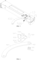
FIG. 3 is a schematic structural diagram showing a connection way between a front connecting rod and a door body of the refrigerator according to some embodiments of the invention; andFIG. 4 shows an exploded view of the front connecting rod and the door body of the refrigerator ofFIG. 3 . As shown inFIGs. 3 and 4 , in some embodiments, therefrigerator 10 may also comprise a slidingassembly 500 which comprises a connectingmember 520 and a slidingmember 510. The connectingmember 520 is fixed to one of the front connectingrod 410 and thedoor body 13. The slidingmember 510 is disposed on another of the front connectingrod 410 and thedoor body 13. The slidingmember 510 is movably connected to the connectingmember 520, to enable the front connectingrod 410 to move relative to thedoor body 13 along an axial direction of therotating shaft 16. - After the
driving mechanism 100 receives a door opening signal, thedriving mechanism 100 is activated to rotate forward, to drive thetransmission mechanism 300 to rotate. Thetransmission mechanism 300 drives thedoor rotation mechanism 400 to rotate, to open thedoor body 13. After thedriving mechanism 100 receives a door closing signal, thedriving mechanism 100 is activated to rotate reversely, to drive thetransmission mechanism 300 to rotate in an opposite direction, and thus thetransmission mechanism 300 drives thedoor rotation mechanism 400 to rotate in the opposite direction to close thedoor body 13. - In some embodiments of the invention, one of the connecting
member 520 and the slidingmember 510 is connected to thefront connecting rod 410, and another of the connectingmember 520 and the slidingmember 510 is connected to thedoor body 13 The slidingmember 510 and the connectingmember 520 are movably connected. When thedoor body 13 is displaced up and down, thedoor body 13 can slide up and down relative to the slidingmember 510, to be capable of reducing a noise generated by a displacement of therefrigerator 10 during transportation, and avoiding a risk of the door opening andclosing device 11 being stuck in movement and unable to open and close the door body normally. Thus, a normal operation of the door opening andclosing device 11 can be ensured, and a damage to components of the door opening andclosing device 11 can also be reduced, to increase a service life of the entire door opening andclosing device 11. - The front connecting
rod 410 may not be moved up and down with thedoor body 13, to be capable of reducing a risk of deformation of the front connectingrod 410 caused by an up and down displacement of thedoor body 13. Thus, a service life of the front connectingrod 410 can be improved, to improve the service life of the entire door opening andclosing device 11. - In some embodiments, a fixing
member 530 is disposed on thedoor body 13. The connectingmember 520 is connected to the fixingmember 530. The slidingmember 510 is connected to thefront connecting rod 410 and is slidably sleeved on the connectingmember 520, to enable the front connectingrod 410 to move along an axial direction of therotating shaft 16 relative to the connectingmember 520. - In some embodiments of the invention, the sliding
member 510 is slidably sleeved on the connectingmember 520. The connectingmember 520 is connected to the fixingmember 530. In a condition that thedoor body 13 is displaced up and down, the slidingmember 510 can slide relative to the connectingmember 520, that is, when thedoor body 13 is displaced up and down, thedoor body 13 can slide up and down relative to the slidingmember 510, while thefront connecting rod 410 may not be displaced up and down with thedoor body 13, to be capable of reducing a noise generated by a displacement of therefrigerator 10 during transportation, and avoiding a risk of the door opening andclosing device 11 being stuck in movement and unable to open and close the door body normally. Thus, a normal operation of the door opening andclosing device 11 can be ensured. It can also reduce a risk of deformation of the front connectingrod 410 caused by an up and down displacement of thedoor body 13, and thus a service life of the front connectingrod 410 can be increased, to increase a service life of the entire door opening andclosing device 11. - It should be noted that the up and down displacement of the
door body 13 refers to a movement along an extension direction of therotation shaft 16. - In some embodiments of the invention, the fixing
member 530 is fixedly disposed on thedoor body 13, and the connectingmember 520 is fixedly connected to the fixingmember 530, that is, thedoor body 13, the fixingmember 530 and the connectingmember 520 are connected as a whole. When thedoor body 13 is displaced up and down, the fixingmember 530 and the connectingmember 520 will be driven to be displaced up and down with thedoor body 13. The slidingmember 510 can slide relative to the connectingmember 520, and thus the up and down displacement of thedoor body 13 will not be transmitted to thefront connecting rod 410 and will not affect a normal operation of the door opening andclosing device 11, to improve the service life of the entire door opening andclosing device 11. - In other words, in a condition that the
door body 13 is displaced up and down, the fixingmember 530 and the connectingmember 520 are displaced up and down along with thedoor body 13, to cause the connectingmember 520 to slide relative to the slidingmember 510. Among the connectingmember 520 and the slidingmember 510, the slidingmember 510 is stationary and the connectingmember 520 moves, to realize a sliding of the connectingmember 520 relative to the slidingmember 510. - In some embodiments, an extension direction of the connecting
member 520 is the same as an extension direction of therotating shaft 16. In a condition that thedoor body 13 is displaced, the slidingmember 510 and the connectingmember 520 slide relative to each other, and the slidingmember 510 slides directly in the extension direction of therotating shaft 16. Thus a movement of the slidingmember 510 in a direction at an angle to the extension direction of therotating shaft 16 can be reduced; an interference between the connectingmember 520 and the slidingmember 510 during sliding can be reduced; and a shaking of the front connectingrod 410 can be minimized as much as possible. The shaking of the front connectingrod 410 affects an effect of door opening and closing of the door opening andclosing device 11. - In some embodiments, a limiting
hole 412 may be formed on thefront connecting rod 410. The slidingmember 510 is disposed in the limitinghole 412. - In some embodiments, the
front connecting rod 410 may be sleeved outside the slidingmember 510. That is, the slidingmember 510 is sleeved on the connectingmember 520. The front connectingrod 410 is sleeved on the slidingmember 510. An order from inside to outside is: the connectingmember 520, the slidingmember 510, and the front connectingrod 410. The slidingmember 510 is disposed in the limitinghole 412, to facilitate an assembly between the slidingmember 510 and the front connectingrod 410. - That is to say, the sliding
member 510 is sleeved on the connectingmember 520. The front connectingrod 410 is sleeved on the slidingmember 510. The slidingmember 510 can slide relative to the connectingmember 520 or rotate relative to the connectingmember 520. The front connectingrod 410 is fixedly connected to the slidingmember 510. The front connectingrod 410, via the slidingmember 510, can slide and rotate relative to the connectingmember 520, to slide and rotate relative to thedoor body 13. When thedoor body 13 is displaced up and down, thedoor body 13 can slide relative to thefront connecting rod 410, while thefront connecting rod 410 can remain stationary, and in turn to be capable of reducing a noise generated by a displacement of therefrigerator 10 during transportation, and avoiding a risk of the door opening andclosing device 11 being stuck in movement and unable to open and close the door body normally. Thus, a normal operation of the door opening andclosing device 11 can be ensured. A deformation of the front connectingrod 410 caused by the displacement of thedoor body 13 can be also recuded, and thus a damage to thefront connecting rod 410 can be reduced, to increase a service life of the front connectingrod 410. - In some embodiments, a fixing
slot 515 may be disposed on an outer peripheral surface of the slidingmember 510. The limitinghole 412 is engaged into the fixingslot 515. - When the sliding
member 510 and the front connectingrod 410 are assembled, the limitinghole 412 is engaged into the fixingslot 515, to be capable of reducing a risk of the front connectingrod 410 separating from the slidingmember 510 and improving a fixing effect between the slidingmember 510 and the front connectingrod 410. - In some embodiments, the limiting
hole 412 is engaged into the fixingslot 515. Since a thickness of the front connectingrod 410 may be smaller than a length of the fixingslot 515, thefront connecting rod 410 may move in a small range. In order to improve a fixing effect of the front connectingrod 410, a circlip is engaged into the fixingslot 515, to enable the front connectingrod 410 to be fixed in the fixingslot 515, and thus a mutual sliding between the front connectingrod 410 and the slidingmember 510 can be avoided, to improve a fixing effect between the front connectingrod 410 and the slidingmember 510. - It is easily understood that, in addition to this, a limiting portion can be protruded on the sliding
member 510, and an engaging hole can be disposed in the limitinghole 412. The limiting portion can be engaged into the engaging hole, to also be capable of achieving a fixed connection between the slidingmember 510 and the front connectingrod 410. - The fixing
member 530 comprises a first limitingportion 534 and a second limitingportion 535 that are oppositely disposed. An end of the connectingmember 520 is connected to the first limitingportion 534, and another end of the connectingmember 520 is connected to the second limitingportion 535. - In some embodiments, the connecting
member 520 may be in a shape of an elongated strip, with an end connected to the first limitingportion 534 and another end connected to the second limitingportion 535, and thus the slidingmember 510 can slide between the first limitingportion 534 and the second limitingportion 535, to prevent the slidingmember 510 from sliding out of the connectingmember 520 and reduce a risk of separating of the slidingmember 510 and the connectingmember 520. - In some embodiments, the first limiting
portion 534 and the second limitingportion 535 are both provided with connectingholes 533. Two ends of the connectingmember 520 are respectively installed in two connectingholes 533. - The
door body 13 has aninstallation groove 15. The first limitingportion 534 is connected to a bottom wall of theinstallation groove 15. The second limitingportion 535 is disposed at an opening of theinstallation groove 15. Two ends of the connectingmember 520 are respectively installed in the two connectingholes 533 and fixedly connected to the connectingholes 533. The connectingmember 520 can be fixed by a simple structure, which has a simple and convenient operation. - In some embodiments, the two
connection holes 533 are concentrically disposed. - The two connecting
holes 533 are concentrically disposed and thus the connectingmember 520 can be disposed in a vertical direction, that is, the same as the rotatingshaft 16. In a condition that thedoor body 13 is displaced, thefront connecting rod 410 can move relative to thedoor body 13, and thus the front connectingrod 410 does not move with thedoor body 13, to be capable of reducing a noise generated by a displacement of therefrigerator 10 during transportation, and avoiding a risk of the door opening andclosing device 11 being stuck in movement and unable to open and close the door body normally. Thus, a normal operation of the door opening andclosing device 11 can be ensured. - In some embodiments, the fixing
member 530 may further comprise atransition portion 537. The first limitingportion 534 and the second limitingportion 535 are connected to thetransition portion 537. The first limitingportion 534 is connected to thedoor body 13. - An end of the
transition portion 537 is connected to the first limitingportion 534, and another end of thetransition portion 537 is connected to the second connectingportion 532. The first limitingportion 534 is fixedly connected to thedoor body 13, to fix the entire fixingmember 530 on thedoor body 13. - It is easily understood that the fixing
member 530 may not comprise thetransition portion 537, and the first limitingportion 534 and the second limitingportion 535 are directly connected to thedoor body 13. The first limitingportion 534 and the second limitingportion 535 are connected through thetransition portion 537 and then connected to thedoor body 13, to be capable of reducing the number of connections between the fixingmember 530 and thedoor body 13, and thus a damage to thedoor body 13 can be reduced. - In some embodiments, the fixing
member 530 is disposed in theinstallation groove 15. The first limitingportion 534 is fixedly connected to a bottom wall of theinstallation groove 15. The first limitingportion 534 may be attached to the bottom wall of theinstallation groove 15 and is fixedly connected to the bottom wall of theinstallation groove 15 by screws. A fixting position being disposed on the bottom wall of theinstallation groove 15 can make an appearance of entire structure integrated and improve aesthetics of an electrical apparatus. - In some embodiments, the first limiting
portion 534 is fixedly connected to the bottom wall of theinstallation groove 15. It is suitable for a structure in which a thickness of thedoor body 13 is relatively large. Thedoor body 13 can be prevented from being pierced by screws to be damaged. - It can be seen that the above is only one implementation way of the fixing
member 530 and the connectingmember 520. In addition, the fixingmember 530 and the connectingmember 520 may have other implementation ways and ways for fixing to thedoor body 13. -
FIG. 5 is a schematic structural diagram showing a connection way between a front connecting rod and a door body of the refrigerator according to some embodiments of the invention; andFIG. 6 shows an exploded view of the front connecting rod and the door body of the refrigerator ofFIG. 5 . As shown inFIG. 5 and FIG. 6 , in some other embodiments, the fixingmember 530 may further comprise aninstallation portion 538. Thetransition portion 537 connects the first limitingportion 534 and the second limitingportion 535. Theinstallation portion 538 is connected to thetransition portion 537 and is connected to thedoor body 13. - The
installation portion 538 is connected to thedoor body 13, to be capable of reducing connection positions between the entire fixingmember 530 and thedoor body 13, and thus the first limitingportion 534 and the second limitingportion 535 only play a role of limiting. - In some other embodiments, the
transition portion 537, the first limitingportion 534, and the second limitingportion 535 are disposed in theinstallation groove 15. - In some embodiments, the
installation portion 538 is disposed outside theinstallation groove 15. The first limitingportion 534 contacts the bottom wall of theinstallation groove 15. Thetransition portion 537 contacts a side wall of theinstallation groove 15. Theinstallation portion 538 is connected to an end of thetransition portion 537 that is connected to the second limitingportion 535, and has an direction that is opposite to that of the second limitingportion 535, to enable theinstallation portion 538 to extend from the opening of the installation groove 15 to an outside of theinstallation groove 15 and be fixedly connected to thedoor body 13. - In some embodiments, the
installation portion 538 is fixedly connected to thedoor body 13 by screws. It is suitable for a structure in which a thickness of thedoor body 13 is relatively small. Thedoor body 13 can be prevented from being pierced by screws to be damaged. -
FIG. 7 is a schematic structural diagram showing a connection way between a front connecting rod and a door body of the refrigerator according to some embodiments of the invention; andFIG. 8 shows an exploded view of the front connecting rod and the door body of the refrigerator ofFIG. 7. FIGs. 7 and 8 show another implementation way of the fixingmember 530 and the connectingmember 520. As shown inFIGs. 7 and 8 , in some embodiments, the fixingmember 530 comprises a fixingportion 531 and a connectingportion 532 that are connected to each other. The connectingportion 532 is connected to thedoor body 13. The connectingmember 520 comprises a connecting shaft 521 and anend cover 523. Theend cover 523 is disposed at an end of the connecting shaft 521. An end of the connecting shaft 521 away from theend cover 523 is connected to the fixingportion 531. The slidingmember 510 is sleeved on the connecting shaft 521, so that the front connectingrod 410 can slide between the fixingportion 531 and theend cover 523. - The fixing
portion 531 and the connectingportion 532 are connected to each other. An end of the connecting shaft 521 is connected to the fixingportion 531, and another end of the connecting shaft 521 is connected to theend cover 523. Thus, the slidingmember 510 can slide between the fixingportion 531 and theend cover 523. The fixingportion 531 and theend cover 523 play a role of limiting to prevent the slidingmember 510 from falling off the connecting shaft 521. - An extension direction of the connecting shaft 521 is the same as the extension direction of the
rotating shaft 16. When thedoor body 13 is displaced up and down, the slidingmember 510 can drive the front connectingrod 410 to directly slide relative to thedoor body 13 along the extension direction of therotating shaft 16, to avoid the front connectingrod 410 from being unable to open or close thedoor body 13 normally due to a deformation of the front connectingrod 410 caused by the displacement of thedoor body 13. - In some embodiments, the connecting shaft 521 and the
end cover 523 are integrally formed. The entire connectingmember 520 is substantially T-shaped, and the fixingportion 531 is disposed at another end of the connecting shaft 521, and thus the connectingmember 520 and the fixingportion 531 are substantially I-shaped. - In some embodiments, a connecting
hole 533 is disposed on the fixingportion 531. An end of the connecting shaft 521 away from theend cover 523 is installed in the connectinghole 533. Similarly, in order to facilitate a cooperation between the connecting shaft 521 and the connectinghole 533, a slidingmember 510 is disposed between the connectinghole 533 and the connecting shaft 521. The connectinghole 533 is engaged into a fixingslot 515 of the slidingmember 510. The slidingmember 510 is sleeved on an end of the connecting shaft 521 away from theend cover 523. If the connecting shaft 521 moves relative to the fixingportion 531 along the direction of therotating shaft 16, the connecting shaft 521 can move relative to the connectinghole 533, to prevent the front connectingrod 410 from moving and reduce a deformation of the front connectingrod 410. - In some embodiments, the fixing
member 530 and the connectingmember 520 are disposed in theinstallation groove 15. Theend cover 523 contacts the bottom wall of theinstallation groove 15. The connectingportion 532 is fixedly connected to the side wall of theinstallation groove 15. - The
end cover 523 is installed on the bottom wall of theinstallation groove 15, to be capable of avoiding the connecting shaft 521 from falling out of the connectinghole 533. The connectingportion 532 is fixedly connected to the side wall of theinstallation groove 15, that is, the connectingmember 520 and fixingmember 530 are both disposed in theinstallation groove 15. The connectingportion 532 is connected to thedoor body 13 in a thickness direction of thedoor body 13. - In some embodiments, the fixing
portion 531 and the connectingportion 532 are connected at an angle. - The
end cover 523 is disposed on the bottom wall of theinstallation groove 15. Theend cover 523 and the fixingportion 531 are respectively disposed at two ends of the connecting shaft 521, that is, theend cover 523 and the fixingportion 531 are oppositely disposed. The fixingportion 531 is disposed close to the opening of theinstallation groove 15. The connectingportion 532 is connected to the side wall of theinstallation groove 15. In order to reduce connections between the fixingportion 531 to the connecting shaft 521, the connectingportion 532 is connected to the side wall of theinstallation groove 15, and thus the fixingportion 531 and the connectingportion 532 are required to be disposed at an angle. - In some embodiments, the fixing
portion 531 and the connectingportion 532 are perpendicular to each other, and thus the connectingportion 532 can be attached to the side wall of theinstallation groove 15, to improve a fixing effect between the connectingportion 532 and theinstallation groove 15 and reduce a deformation of the connectingportion 532. - The connecting
portion 532 and the side wall of theinstallation groove 15 are connected by screws. A connection by screw is convenient and simple and easy to operate. -
FIG. 9 is a schematic structural diagram showing a connection way between a front connecting rod and a door body of the refrigerator according to some embodiments of the invention; andFIG. 10 shows an exploded view of the front connecting rod and the door body of the refrigerator ofFIG. 9 . As shown inFIG. 9 and FIG. 10 , in some embodiments, the slidingmember 510 has aninstallation hole 514. The connectingmember 520 is disposed on thefront connecting rod 410. The connectingmember 520 is installed in theinstallation hole 514. - The connecting
member 520 is disposed on thefront connecting rod 410. The connectingmember 520 is disposed in theinstallation hole 514. The connectingmember 520 can be rotated relative to theinstallation hole 514. In a condition that the door opening andclosing device 11 is activated, thetransmission mechanism 300 drives thedoor rotation mechanism 400 to rotate, and the front connectingrod 410, through the connectingmember 520, drives thedoor body 13 to rotate, to open thedoor body 13. - In some embodiments, the connecting
member 520, theinstallation hole 514, and the fixinghole 14 are concentrically disposed. The fixinghole 14, the connectingmember 520 and theinstallation hole 514 are concentrically disposed. Thus, a door-opening stability can be improved when the front connectingrod 410 drives thedoor body 13 to rotate. - In some embodiments, a shape of the sliding
member 510 matches a shape of the fixinghole 14. The shape of the slidingmember 510 matching the shape of the fixinghole 14 enables the slidingmember 510 to move in an extension direction of the fixinghole 14, to reduce an influence of the up and down displacement of thedoor body 13 on thefront connecting rod 410. - In some embodiments, a length of the fixing
hole 14 is greater than a length of the slidingmember 510. During a displacement of thedoor body 13, a larger depth of the fixinghole 14 can provide a larger sliding space for the slidingmember 510, to be capable of avoiding as much as possible a situation in which a bottom of the slidingmember 510 abuts against a bottom wall of the fixinghole 14 due to excessive up and down displacement of thedoor body 13, causing thefront connecting rod 410 to move accordingly. - In some embodiments, a fixing
hole 14 is disposed on thedoor body 13. The slidingmember 510 is sleeved on thefront connecting rod 410 and installed in the fixinghole 14. In a condition that the door opening andclosing device 11 opens or closes thedoor body 13, if thedoor body 13 is displaced up and down, the slidingmember 510 can move relative to the fixinghole 14 along an axial direction of therotating shaft 16, that is, when thedoor body 13 is displaced up and down, thedoor body 13 can slide up and down relative to the slidingmember 510, and the front connectingrod 410 will not be displaced up and down with thedoor body 13. Thus an adaptability, reliability and usage experience of thedoor body 13 can be improved. At the same time, an impact of the up and down displacement of thedoor body 13 on the door opening andclosing device 11 can be reduced. A situation in which the door opening andclosing device 11 gets stuck in movement due to the up and down displacement of thedoor body 13 can be reduced. A damage to components of the door opening andclosing device 11 can be reduced. A service life of the entire door opening andclosing device 11 can be increased. - Of cause, as the
front connecting rod 410 is directly connected to thedoor body 13, a risk of deformation of the front connectingrod 410 caused by the up and down displacement of thedoor body 13 can also be reduced. Thus a service life of the front connectingrod 410 can be improved, to be capable of improving the service life of the entire door opening andclosing device 11. - When the
door body 13 is opened or closed, if thedoor body 13 is displaced up and down, the slidingmember 510 can move along an axial direction of therotating shaft 16 relative to the fixinghole 14, while thefront connecting rod 410 can remain stationary. Thus, the up and down displacement of thedoor body 13 will not be transmitted to thefront connecting rod 410. An impact of the up and down displacement of thedoor body 13 on the door opening andclosing device 11 can be reduced. A situation in which the door opening andclosing device 11 gets stuck in movement due to the up and down displacement of thedoor body 13 can be reduced. A damage to components of the door opening andclosing device 11 can be reduced. A service life of the entire door opening andclosing device 11 can be increased. - It should be noted that the up and down displacement of the
door body 13 refers to a movement along an extension direction of therotation shaft 16. - In some embodiments, the fixing
hole 14 is disposed above thedoor body 13, that is, disposed on an upper surface of thedoor body 13. The front connectingrod 410 is connected to the slidingmember 510. The slidingmember 510 is disposed in the fixinghole 14. Thus, thefront connecting rod 410 is disposed above thedoor body 13, and from above thedoor body 13 drives thedoor body 13 to rotate. - In some embodiments, the fixing
hole 14 has a fixing surface 14d. Astop surface 511 is provided on the slidingmember 510. The fixing surface 14d cooperates with thestop surface 511. In some embodiments, a shape of the fixing surface 14d is different from a shape of the fixinghole 14, and a shape of thestop surface 511 is different from a shape of the slidingmember 510. - The shape of the fixing surface 14d being different from the shape of the fixing
hole 14 indicates that the shape of the fixing surface 14d is different from a shape of a hole wall of the fixinghole 14. Similarly, the shape of thestop surface 511 being different from the shape of the slidingmember 510 indicates that the shape of thestop surface 511 is different from a contour of the slidingmember 510. - The shape of the fixing surface 14d is different from that of the fixing
hole 14, and the shape of thestop surface 511 is different from that of the slidingmember 510. After the slidingmember 510 is installed in the fixinghole 14, the slidingmember 510 cannot be rotated relative to the fixinghole 14, to avoid a situation in which the slidingmember 510 is rotated relative to thedoor body 13 when the front connectingrod 410 drives thedoor body 13 to rotate. This situation results in that the front connectingrod 410 is unable to drive thedoor body 13 to be opened or closed. - In some embodiments, the shape of the
stop surface 511 matches the shape of the fixing surface 14d, which indicates that the shapes of thestop surface 511 and the fixing surface 14d are the same. Optionally, if the fixing surface 14d is a plane, thestop surface 511 is also a plane. If the fixing surface 14d is a curved surface, thestop surface 511 is also a curved surface, as long as the two can be matched. - It should be noted that the fixing surface 14d is disposed on the fixing
hole 14. The shape of the fixing surface 14d being different from the shape of the fixinghole 14 indicates that the shape of the fixing surface 14d is different from shapes of other portions of the fixinghole 14. Similarly, thestop surface 511 is disposed on the slidingmember 510. The shape of thestop surface 511 being different from the shape of the slidingmember 510 indicates that the shape of thestop surface 511 is different from shapes of other portions of the slidingmember 510. - In some embodiments, the sliding
member 510 is cylindrical. Thestop surface 511 is disposed on a peripheral wall of the slidingmember 510, that is, the slidingmember 510 is an incomplete cylinder, and is a cylinder with a notch. Similarly, the fixinghole 14 is circular, thestop surface 511 is disposed on the hole wall of the fixinghole 14, and the fixinghole 14 is circular with a notch. - In some embodiments, the fixing
hole 14 comprises afixing section 14b and a connectingsection 14c that are interconnected. The slidingmember 510 comprises a stop section and aninstallation section 513 that are interconnected. The installation section is disposed close to thefront connecting rod 410. The fixingsection 14b cooperates with the stop section. The connectingsection 14c cooperates with the installation section. The fixing surface 14d is disposed on thefixing section 14b. Thestop surface 511 is disposed on the stop section. - In some embodiments, the installation section is disposed close to the
front connecting rod 410. The fixingsection 14 b is disposed close to a bottom of the fixinghole 14, and thestop surface 511 is disposed at a lower portion, to facilitate an installation of the slidingmember 510 and reduce a difficulty in installing the slidingmember 510 to the fixinghole 14. - In some embodiments, the fixing
section 14b is disposed below the connectingsection 14c. In order to make the connectingsection 14c to cooperate with the installation section, and make thefixing section 14b to cooperate with the stop section, it is required to dispose thefixing section 14b below the connectingsection 14c. - In some embodiments, the fixing
hole 14 is circular. A diameter of the fixingsection 14b is smaller than a diameter of the connectingsection 14c. The slidingmember 510 is cylindrical. A diameter of the stop section is smaller than a diameter of the installation section. - The diameter of the fixing
section 14b is smaller than the diameter of the connectingsection 14c. The diameter of the stop section is smaller than the diameter of the installation section. Since the fixing surface 14d is disposed on thefixing section 14b, the fixingsection 14b is not a complete cylinder. The fixingsection 14b and the connectingsection 14c are concentrically disposed. A diameter of the fixingsection 14b refers to twice a radius of an arc portion of the fixingsection 14b. - Similarly, the
stop surface 511 is disposed on the stop section, and thus thestop surface 511 is also not a complete cylinder. The stop section and the installation section are concentrically disposed. A diameter of the stop section refers to twice a radius of an arc portion of the stop section. - To sum up, one of the connecting
member 520 and the slidingmember 510 is connected to thefront connecting rod 410, and another of the connectingmember 520 and the slidingmember 510 is connected to thedoor body 13. The slidingmember 510 and the connectingmember 520 are slidably connected. When thedoor body 13 is displaced up and down, thedoor body 13 can slide up and down relative to the slidingmember 510, while thefront connecting rod 410 will not be displaced up and down with thedoor body 13. Thus, a risk of deformation of the front connectingrod 410 due to the up and down displacement of thedoor body 13 can be reduced. A situation in which the door opening andclosing device 11 gets stuck in movement due to the up and down displacement of thedoor body 13 can be reduced to a certain extent. A damage to components of the door opening andclosing device 11 due to the up and down displacement of thedoor body 13 can be reduced to a certain extent. Thus, a service life of the front connectingrod 410 can be increased, to increase a service life of the entire door opening andclosing device 11. - In the description of this specification, the description with reference to the terms "one embodiment", "some embodiments", "example", "specific example", or "some examples" and so on means that the specific features, structures, materials or characteristics described in conjunction with the embodiment or example are comprised in at least one embodiment or example of the invention. In the specification, the exemplary expressions of the above terms do not necessarily refer to the same embodiment or example. Furthermore, the specific features, structures, materials, or characteristics described may be combined in any suitable manner in any one or more embodiments or examples. Furthermore, those skilled in the art may combine and couple different embodiments or examples described in this specification.
Claims (16)
- A refrigerator, comprising:a main body formed with an accommodation space that has an opening;a door body rotatably disposed on the main body via a rotating shaft to close or open the opening;a door opening and closing device disposed on the main body and connected to the door body, wherein when the door opening and closing device is activated, the door opening and closing device drives the door body to rotate relative to the main body, so as to open or close the door body, and the door opening and closing device comprising a front connecting rod; anda sliding assembly comprising a connecting member and a sliding member, wherein the connecting member is fixed to one of the front connecting rod and the door body, the sliding member being disposed on another of the front connecting rod and the door body, the sliding member being movably connected to the connecting member, to enable the front connecting rod to move along an axial direction of the rotating shaft relative to the door body.
- The refrigerator according to claim 1, wherein a fixing hole is disposed on the door body, the connecting member being disposed on the front connecting rod, the sliding member being sleeved onto the connecting member and installed in the fixing hole, and wherein in a condition that the door opening and closing device opens or closes the door body, the sliding member is able to move along the axial direction of the rotating shaft in the fixing hole.
- The refrigerator according to claim 1 or 2, wherein the fixing hole has a fixing surface, a stop surface being provided on the sliding member, the fixing surface cooperating with the stop surface, wherein a shape of the fixing surface is different from a shape of the fixing hole, a shape of the stop surface being different from a shape of the sliding member.
- The refrigerator according to any one of claims 1 to 3, wherein the fixing hole comprises a fixing section and a connecting section that are interconnected, and wherein the sliding member comprises a stop section and an installation section that are interconnected, the installation section being disposed close to the front connecting rod, the fixing section cooperating with the stop section, the connecting section cooperating with the installation section, the fixing surface being disposed on the fixing section, and the stop surface being disposed on the stop section.
- The refrigerator according to claim 3 or 4, wherein the shape of the stop surface matches the shape of the fixing surface.
- The refrigerator according to any one of claims 1 to 5, wherein a fixing member is disposed on the door body, the connecting member being connected to the fixing member, the sliding member being fixedly connected to the front connecting rod and being sleeved onto the connecting member, so as to enable the front connecting rod to move along an extension direction of the rotating shaft relative to the connecting member.
- The refrigerator according to any one of claims 1 to 6, wherein a limiting hole is formed on the front connecting rod, the sliding member being disposed in the limiting hole.
- The refrigerator according to claim 7, wherein a fixing slot is disposed on an outer peripheral surface of the sliding member, the limiting hole is engaged into the fixing slot.
- The refrigerator according to any one of claims 6 to 8, wherein the fixing member comprises a fixing portion and a connecting portion that are interconnected, the connecting portion being connected to the door body, wherein the connecting member comprises a connecting shaft and an end cover, the end cover being disposed at an end of the connecting shaft, an end of the connecting shaft away from the end cover being connected to the fixing portion, the refrigerator being sleeved onto the connecting shaft, so as to make the front connecting rod to be capable of sliding between the fixing portion and the end cover.
- The refrigerator according to claim 9, wherein the door body has an installation groove, the fixing member and the connecting member being disposed in the installation groove, the end cover contacting a bottom wall of the installation groove, the connecting portion being fixedly connected to a side wall of the installation groove.
- The refrigerator according to any one of claims 6 to 8, wherein the fixing member comprises a first limiting portion and a second limiting portion that are oppositely disposed, an end of the connecting member being connected to the first limiting portion, an other end of the connecting member being connected to the second limiting portion.
- The refrigerator according to claim 11, wherein the fixing member further comprises a transition portion, the first limiting portion and the second limiting portion being connected through the transition portion, the first limiting portion being connected to the door body.
- The refrigerator according to claim 11 or 12, wherein the door body has an installation groove, the fixing member being disposed in the installation groove, the first limiting portion being fixedly connected to a bottom wall of the installation groove.
- The refrigerator according to any one of claims 11 to 13, wherein the fixing member further comprises a transition portion and an installation portion, the transition portion connecting the first limiting portion and the second limiting portion, the installation portion being connected to the transition portion and to the door body.
- The refrigerator according to claim 12 or 14, wherein the door body has an installation groove, and wherein the transition portion, the first limiting portion and the second limiting portion are disposed in the installation groove, the installation portion being disposed outside the installation groove.
- The refrigerator according to any one of claims 1 to 15, wherein the door opening and closing device further comprises a driving mechanism, a transmission mechanism and a door rotation mechanism, the driving mechanism and the transmission mechanism being both mounted on the main body, wherein the door rotation mechanism further comprises a rear connecting rod, an end of the rear connecting rod being connected to the transmission mechanism, an other end of the rear connecting rod being connected to an end of the front connecting rod, an end of the front connecting rod away from the rear connecting rod being connected to the sliding member.
Applications Claiming Priority (2)
| Application Number | Priority Date | Filing Date | Title |
|---|---|---|---|
| CN202211145486.9A CN117781540A (en) | 2022-09-20 | 2022-09-20 | a refrigerator |
| PCT/CN2023/103237 WO2024060751A1 (en) | 2022-09-20 | 2023-06-28 | Refrigerator |
Publications (2)
| Publication Number | Publication Date |
|---|---|
| EP4582756A1 true EP4582756A1 (en) | 2025-07-09 |
| EP4582756A4 EP4582756A4 (en) | 2025-12-24 |
Family
ID=90378581
Family Applications (1)
| Application Number | Title | Priority Date | Filing Date |
|---|---|---|---|
| EP23867046.7A Pending EP4582756A4 (en) | 2022-09-20 | 2023-06-28 | REFRIGERATOR |
Country Status (5)
| Country | Link |
|---|---|
| US (1) | US20260098438A1 (en) |
| EP (1) | EP4582756A4 (en) |
| JP (1) | JP2025532096A (en) |
| CN (1) | CN117781540A (en) |
| WO (1) | WO2024060751A1 (en) |
Family Cites Families (11)
| Publication number | Priority date | Publication date | Assignee | Title |
|---|---|---|---|---|
| JP6223765B2 (en) * | 2013-09-30 | 2017-11-01 | 日本電産サンキョー株式会社 | refrigerator |
| CN206944568U (en) * | 2017-07-20 | 2018-01-30 | Tcl家用电器(合肥)有限公司 | Refrigerator |
| CN209588499U (en) * | 2019-01-28 | 2019-11-05 | 合肥华凌股份有限公司 | Linkage and refrigerator with it |
| CN111503981B (en) * | 2020-04-23 | 2021-07-27 | 长虹美菱股份有限公司 | Refrigerator automatic door opening and closing device and refrigerator |
| CN212337015U (en) * | 2020-07-21 | 2021-01-12 | 南京中竞科智能科技有限公司 | Rotating mechanism and electric appliance |
| CN113958222A (en) * | 2020-07-21 | 2022-01-21 | 南京中竞科智能科技有限公司 | Rotating mechanism, electric appliance and control method for automatically opening and closing door |
| CN114688817B (en) * | 2020-12-31 | 2023-03-17 | 青岛海尔电冰箱有限公司 | Automatic door opening and closing device for refrigerator and refrigerator with same |
| CN218324527U (en) * | 2022-09-20 | 2023-01-17 | 合肥美的电冰箱有限公司 | an electrical device |
| CN218092686U (en) * | 2022-09-20 | 2022-12-20 | 合肥美的电冰箱有限公司 | an electrical device |
| CN218092687U (en) * | 2022-09-20 | 2022-12-20 | 合肥美的电冰箱有限公司 | Electrical equipment |
| CN218328818U (en) * | 2022-09-20 | 2023-01-17 | 合肥美的电冰箱有限公司 | a refrigerator |
-
2022
- 2022-09-20 CN CN202211145486.9A patent/CN117781540A/en active Pending
-
2023
- 2023-06-28 US US19/112,269 patent/US20260098438A1/en active Pending
- 2023-06-28 JP JP2025517193A patent/JP2025532096A/en active Pending
- 2023-06-28 WO PCT/CN2023/103237 patent/WO2024060751A1/en not_active Ceased
- 2023-06-28 EP EP23867046.7A patent/EP4582756A4/en active Pending
Also Published As
| Publication number | Publication date |
|---|---|
| CN117781540A (en) | 2024-03-29 |
| US20260098438A1 (en) | 2026-04-09 |
| JP2025532096A (en) | 2025-09-29 |
| EP4582756A4 (en) | 2025-12-24 |
| WO2024060751A1 (en) | 2024-03-28 |
Similar Documents
| Publication | Publication Date | Title |
|---|---|---|
| EP4137659B1 (en) | Door assembly and storage cabinet | |
| US8365470B1 (en) | Lead screw operator | |
| US20080000052A1 (en) | Refrigerator | |
| US20190093410A1 (en) | Door opening and closing device and refrigerator | |
| CN212253341U (en) | A kind of refrigerator | |
| CN109083529A (en) | A kind of refrigerator door closer-holder with any hovering function | |
| CN218328818U (en) | a refrigerator | |
| US20260098438A1 (en) | Refrigerator | |
| CN100533018C (en) | Refrigerator | |
| CN218092686U (en) | an electrical device | |
| CN113606832B (en) | Refrigerator and door opening and closing mechanism thereof | |
| EP4206589B1 (en) | Refrigerator | |
| CN218092687U (en) | Electrical equipment | |
| CN218324527U (en) | an electrical device | |
| CN114812084A (en) | Turnover beam assembly, door assembly and storage cabinet | |
| CN112212594B (en) | A kind of refrigerator | |
| CN221256481U (en) | Functional shaft and hinge device | |
| CN113982401B (en) | Refrigerator | |
| CN117803274A (en) | Automatic door closing device for vertical refrigerator and vertical refrigerator | |
| EP4585782A1 (en) | Door opening and closing device and electrical apparatus | |
| CN116624057A (en) | A door switch device and electrical equipment | |
| EP1959081A1 (en) | Door closer for left-hand side openable door and right-hand side openable door | |
| CN222951316U (en) | Transmission assembly, flip beam mechanism and refrigerator | |
| CN116624054A (en) | A door switch device and electrical equipment | |
| EP4585872A1 (en) | Refrigerator |
Legal Events
| Date | Code | Title | Description |
|---|---|---|---|
| STAA | Information on the status of an ep patent application or granted ep patent |
Free format text: STATUS: THE INTERNATIONAL PUBLICATION HAS BEEN MADE |
|
| PUAI | Public reference made under article 153(3) epc to a published international application that has entered the european phase |
Free format text: ORIGINAL CODE: 0009012 |
|
| STAA | Information on the status of an ep patent application or granted ep patent |
Free format text: STATUS: REQUEST FOR EXAMINATION WAS MADE |
|
| 17P | Request for examination filed |
Effective date: 20250331 |
|
| AK | Designated contracting states |
Kind code of ref document: A1 Designated state(s): AL AT BE BG CH CY CZ DE DK EE ES FI FR GB GR HR HU IE IS IT LI LT LU LV MC ME MK MT NL NO PL PT RO RS SE SI SK SM TR |
|
| REG | Reference to a national code |
Ref country code: DE Ref legal event code: R079 Free format text: PREVIOUS MAIN CLASS: F25D0011000000 Ipc: F25D0023020000 |
|
| A4 | Supplementary search report drawn up and despatched |
Effective date: 20251120 |
|
| DAV | Request for validation of the european patent (deleted) | ||
| DAX | Request for extension of the european patent (deleted) | ||
| RIC1 | Information provided on ipc code assigned before grant |
Ipc: F25D 23/02 20060101AFI20251114BHEP Ipc: E05F 15/63 20150101ALI20251114BHEP Ipc: E05D 1/04 20060101ALI20251114BHEP Ipc: E05F 15/00 20150101ALI20251114BHEP Ipc: E05F 15/614 20150101ALI20251114BHEP |