EP4582749A1 - Air conditioner and air deflector thereof - Google Patents
Air conditioner and air deflector thereof Download PDFInfo
- Publication number
- EP4582749A1 EP4582749A1 EP23881415.6A EP23881415A EP4582749A1 EP 4582749 A1 EP4582749 A1 EP 4582749A1 EP 23881415 A EP23881415 A EP 23881415A EP 4582749 A1 EP4582749 A1 EP 4582749A1
- Authority
- EP
- European Patent Office
- Prior art keywords
- air
- plate
- deflection part
- shaped body
- slits
- Prior art date
- Legal status (The legal status is an assumption and is not a legal conclusion. Google has not performed a legal analysis and makes no representation as to the accuracy of the status listed.)
- Pending
Links
Images




Classifications
-
- F—MECHANICAL ENGINEERING; LIGHTING; HEATING; WEAPONS; BLASTING
- F24—HEATING; RANGES; VENTILATING
- F24F—AIR-CONDITIONING; AIR-HUMIDIFICATION; VENTILATION; USE OF AIR CURRENTS FOR SCREENING
- F24F13/00—Details common to, or for air-conditioning, air-humidification, ventilation or use of air currents for screening
- F24F13/08—Air-flow control members, e.g. louvres, grilles, flaps or guide plates
- F24F13/10—Air-flow control members, e.g. louvres, grilles, flaps or guide plates movable, e.g. dampers
- F24F13/14—Air-flow control members, e.g. louvres, grilles, flaps or guide plates movable, e.g. dampers built up of tilting members, e.g. louvre
-
- F—MECHANICAL ENGINEERING; LIGHTING; HEATING; WEAPONS; BLASTING
- F24—HEATING; RANGES; VENTILATING
- F24F—AIR-CONDITIONING; AIR-HUMIDIFICATION; VENTILATION; USE OF AIR CURRENTS FOR SCREENING
- F24F1/00—Room units for air-conditioning, e.g. separate or self-contained units or units receiving primary air from a central station
- F24F1/0007—Indoor units, e.g. fan coil units
- F24F1/0011—Indoor units, e.g. fan coil units characterised by air outlets
-
- F—MECHANICAL ENGINEERING; LIGHTING; HEATING; WEAPONS; BLASTING
- F24—HEATING; RANGES; VENTILATING
- F24F—AIR-CONDITIONING; AIR-HUMIDIFICATION; VENTILATION; USE OF AIR CURRENTS FOR SCREENING
- F24F13/00—Details common to, or for air-conditioning, air-humidification, ventilation or use of air currents for screening
- F24F13/08—Air-flow control members, e.g. louvres, grilles, flaps or guide plates
-
- F—MECHANICAL ENGINEERING; LIGHTING; HEATING; WEAPONS; BLASTING
- F24—HEATING; RANGES; VENTILATING
- F24F—AIR-CONDITIONING; AIR-HUMIDIFICATION; VENTILATION; USE OF AIR CURRENTS FOR SCREENING
- F24F1/00—Room units for air-conditioning, e.g. separate or self-contained units or units receiving primary air from a central station
- F24F1/0007—Indoor units, e.g. fan coil units
- F24F1/0043—Indoor units, e.g. fan coil units characterised by mounting arrangements
- F24F1/0047—Indoor units, e.g. fan coil units characterised by mounting arrangements mounted in the ceiling or at the ceiling
-
- F—MECHANICAL ENGINEERING; LIGHTING; HEATING; WEAPONS; BLASTING
- F24—HEATING; RANGES; VENTILATING
- F24F—AIR-CONDITIONING; AIR-HUMIDIFICATION; VENTILATION; USE OF AIR CURRENTS FOR SCREENING
- F24F13/00—Details common to, or for air-conditioning, air-humidification, ventilation or use of air currents for screening
- F24F13/22—Means for preventing condensation or evacuating condensate
-
- F—MECHANICAL ENGINEERING; LIGHTING; HEATING; WEAPONS; BLASTING
- F24—HEATING; RANGES; VENTILATING
- F24F—AIR-CONDITIONING; AIR-HUMIDIFICATION; VENTILATION; USE OF AIR CURRENTS FOR SCREENING
- F24F13/00—Details common to, or for air-conditioning, air-humidification, ventilation or use of air currents for screening
- F24F13/22—Means for preventing condensation or evacuating condensate
- F24F2013/221—Means for preventing condensation or evacuating condensate to avoid the formation of condensate, e.g. dew
-
- F—MECHANICAL ENGINEERING; LIGHTING; HEATING; WEAPONS; BLASTING
- F24—HEATING; RANGES; VENTILATING
- F24F—AIR-CONDITIONING; AIR-HUMIDIFICATION; VENTILATION; USE OF AIR CURRENTS FOR SCREENING
- F24F2221/00—Details or features not otherwise provided for
- F24F2221/14—Details or features not otherwise provided for mounted on the ceiling
-
- F—MECHANICAL ENGINEERING; LIGHTING; HEATING; WEAPONS; BLASTING
- F24—HEATING; RANGES; VENTILATING
- F24F—AIR-CONDITIONING; AIR-HUMIDIFICATION; VENTILATION; USE OF AIR CURRENTS FOR SCREENING
- F24F2221/00—Details or features not otherwise provided for
- F24F2221/28—Details or features not otherwise provided for using the Coanda effect
Definitions
- a technical problem to be solved by embodiments of the present disclosure is to reduce dust adsorbed by an air deflector of an air conditioner.
- the first air deflection part and the second air deflection part are each constructed into an elongated plate-shaped structure.
- the first air deflection part, the second air deflection part, and the one or more slits extend in the same direction; and two ends of the first air deflection part are respectively connected to two ends of the second air deflection part.
- a cross-section of the first air deflection part and a cross-section of the second air deflection part are each arc-shaped and arch towards the same side.
- the one or more slits has a width ranging from 5 mm to 15 mm.
- the air deflector further comprises a reinforcement part connected to the parts of the plate-shaped body located at the two sides of the one or more slits.
- the reinforcement part is constructed into a plate-shaped structure perpendicular to the plate-shaped body.
- a plurality of reinforcement parts is provided and sequentially arranged at an interval along the one or more slits.
- the plate-shaped body is further provided with a plurality of protruding ridges arranged side by side at a surface of the plate-shaped body.
- Embodiments of the present disclosure also provide an air conditioner.
- the air conditioner comprises the air deflector as described above and a body having an air outflowing opening.
- the air deflector is disposed at the air outflowing opening and rotatably connected to the body.
- an extending direction of each of the one or more slits is perpendicular to an air outflowing direction of the air outflowing opening.
- a part of cold airflow moves along one surface of the plate-shaped body of the air deflector, flows from a front end of the plate-shaped body to a tail end of the plate-shaped body, and finally moves in a direction towards which the tail end faces, thereby changing an air outflowing direction of the air outflowing opening.
- a negative-pressure region is formed near the other surface of the plate-shaped body. Another part of the cold airflow expelled from the air outflowing opening passes through the one or more slits when passing by the one or more slits, and the cold airflow is thus sprayed towards the above-described negative-pressure region.
- the cold airflow sprayed towards the negative-pressure region can prevent humid and hot air around the air deflector from converging to the negative-pressure region, thereby preventing the humid and hot air from coming into contact with the air deflector and generating condensation on the air deflector. In this way, stains on the air deflector caused by the condensation adsorbing dust are greatly reduced.
- the air conditioner 1 comprises a body 11 and an air deflector 12.
- the body 11 may be constructed into a substantially rectangular-shaped structure.
- the body 11 has an air outflowing opening 111 configured to allow air to flow outwards.
- the air outflowing opening 111 may be constructed into a straight elongated opening.
- the air outflowing opening 111 is formed close to a side of the body 11. In this embodiment, four air outflowing openings 111 are respectively formed along four edges of the body 11, and the four air outflowing openings 111 allow air to flow outwards from four sides of the body 11 respectively.
- a side of the plate-shaped body 120 is a front end, and another side of the plate-shaped body 120 is a tail end.
- the front end is closer to the air outflowing opening 111 of the body 11 than a leeward side.
- the plate-shaped body 120 further has a slit located between the front end and the tail end, and the slit penetrates the plate-shaped body 120 in a thickness direction of the plate-shaped body 120.
- the plate-shaped body 120 may have one or more slits.
- the slit may be constructed into an elongated shape, and an extending direction of the slit is preferably perpendicular to the air outflowing direction of the air outflowing opening 111.
Landscapes
- Engineering & Computer Science (AREA)
- Chemical & Material Sciences (AREA)
- Combustion & Propulsion (AREA)
- Mechanical Engineering (AREA)
- General Engineering & Computer Science (AREA)
- Air-Flow Control Members (AREA)
- Air Filters, Heat-Exchange Apparatuses, And Housings Of Air-Conditioning Units (AREA)
Abstract
Description
- This application claims priority to
Chinese Patent Application No. 202222856058.9, titled "air conditioner and air deflector thereof", and filed on October 27, 2022 - The present disclosure relates to a refrigeration device, and in particular, to an air conditioner and an air deflector thereof.
- When the air conditioner performs cooling, cold air expelled from an air outflowing opening passes through an air deflector. In this case, a flow velocity of the cold air is high, which leads to a low-pressure region formed nearby, thereby attracting nearby humid and hot air to gather in a region below the air deflector. The humid and hot air is in contact with the cold air at the air deflector, and therefore condensation is generated on a lower surface of the air deflector, which absorbs dust and thus causes the air deflector to be dirty.
- In addition, when the cold air is blown out along the lower surface of the air deflector, a vortex is formed at a tail end of the air deflector due to a Coanda effect of the air, thereby drawing in nearby warm and humid airflow, which forms the condensation. After the condensation absorbs the dust, it further aggravates the dirtiness of the air deflector.
- The following is a summary of a subject matter described in detail herein. This summary is not intended to limit the scope of the claims.
- A technical problem to be solved by embodiments of the present disclosure is to reduce dust adsorbed by an air deflector of an air conditioner.
- Technical solutions of embodiments of the present disclosure to solve the above technical problem will be described below.
- There is provided an air deflector. The air deflector comprises a plate-shaped body. The plate-shaped body has one or more slits penetrating the plate-shaped body.
- In an exemplary embodiment, the plate-shaped body comprises a first air deflection part and a second air deflection part disposed at a side of the first air deflection part. The one or more slits has an air inlet end and an air outlet end away from the air inlet end. The one or more slits are provided between the first air deflection part and the second air deflection part. The air inlet end faces towards closer to the side of the first air deflection part, and the air outlet end faces towards closer to the side of the second air deflection part.
- In an exemplary embodiment, the first air deflection part and the second air deflection part are each constructed into an elongated plate-shaped structure. The first air deflection part, the second air deflection part, and the one or more slits extend in the same direction; and two ends of the first air deflection part are respectively connected to two ends of the second air deflection part.
- In an exemplary embodiment, a cross-section of the first air deflection part and a cross-section of the second air deflection part are each arc-shaped and arch towards the same side.
- In an exemplary embodiment, a ratio of a length of the one or more slits to a length of the plate-shaped body ranges from 0.7 to 0.9.
- In an exemplary embodiment, the one or more slits has a width ranging from 5 mm to 15 mm.
- In an exemplary embodiment, the air deflector further comprises a reinforcement part connected to the parts of the plate-shaped body located at the two sides of the one or more slits.
- In an exemplary embodiment, the reinforcement part is constructed into a plate-shaped structure perpendicular to the plate-shaped body.
- In an exemplary embodiment, a plurality of reinforcement parts is provided and sequentially arranged at an interval along the one or more slits.
- In an exemplary embodiment, the plate-shaped body is further provided with a plurality of protruding ridges arranged side by side at a surface of the plate-shaped body.
- Embodiments of the present disclosure also provide an air conditioner. The air conditioner comprises the air deflector as described above and a body having an air outflowing opening. The air deflector is disposed at the air outflowing opening and rotatably connected to the body.
- In an exemplary embodiment, an extending direction of each of the one or more slits is perpendicular to an air outflowing direction of the air outflowing opening.
- When the air conditioner performs cooling, and the cold air is expelled outward from the air outflowing opening of the body, a part of cold airflow moves along one surface of the plate-shaped body of the air deflector, flows from a front end of the plate-shaped body to a tail end of the plate-shaped body, and finally moves in a direction towards which the tail end faces, thereby changing an air outflowing direction of the air outflowing opening. Simultaneously, a negative-pressure region is formed near the other surface of the plate-shaped body. Another part of the cold airflow expelled from the air outflowing opening passes through the one or more slits when passing by the one or more slits, and the cold airflow is thus sprayed towards the above-described negative-pressure region. The cold airflow sprayed towards the negative-pressure region can prevent humid and hot air around the air deflector from converging to the negative-pressure region, thereby preventing the humid and hot air from coming into contact with the air deflector and generating condensation on the air deflector. In this way, stains on the air deflector caused by the condensation adsorbing dust are greatly reduced.
- Other aspects can be understood after reading and understanding accompanying drawings and detailed description.
-
-
FIG. 1 is a schematic perspective view of an air conditioner according to an embodiment of the present disclosure. -
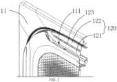
FIG. 2 is a schematic partial view of an air conditioner according to an embodiment of the present disclosure. -
FIG. 3 is a schematic bottom view of an air conditioner according to an embodiment of the present disclosure. -
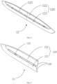
FIG. 4 is a schematic front perspective view of an air deflector according to an embodiment of the present disclosure. -
FIG. 5 is a schematic half-cross-sectional front view of an air deflector according to an embodiment of the present disclosure. -
FIG. 6 is a schematic back perspective view of an air deflector according to an embodiment of the present disclosure. -
FIG. 7 is a schematic partial back view of an air deflector according to an embodiment of the present disclosure. -
FIG. 8 is a schematic partial cross-sectional view of an air conditioner according to an embodiment of the present disclosure. - In the accompanying drawings, a list of components represented by respective reference numerals is as follows:
1, air conditioner; 11, body; 111, air outflowing opening; 12, air deflector; 120, plate-shaped body; 121, first air deflection part; 122, second air deflection part; 123, slit; 124, air inlet end; 125, air outlet end; 126, connector; 127, reinforcement part; 128, protruding ridge. - Principles and features of embodiments of the present disclosure will be described below with reference to the accompanying drawings. Examples given are only used to explain the present disclosure and are not used to limit the scope of the present disclosure.
- As shown in
FIGS. 1 to 3, FIGS. 1 to 3 show a structure of anair conditioner 1 in an embodiment. Theair conditioner 1 may be a ceiling cassette air conditioner, a wall-mounted air conditioner, a cabinet air conditioner, etc. The ceiling cassette air conditioner is taken as an example in this embodiment. The ceiling cassette air conditioner, also known as a cassette air conditioner or a flush-mounted ceiling air conditioner, is a built-in air conditioner that can be embedded into a ceiling or a suspended ceiling, which can fully utilize indoor top space and save floor mounting space. Meanwhile, the ceiling cassette air conditioner is embedded into the ceiling or the suspended ceiling, which is aesthetically pleasing. - The
air conditioner 1 comprises abody 11 and anair deflector 12. Thebody 11 may be constructed into a substantially rectangular-shaped structure. Thebody 11 has an air outflowingopening 111 configured to allow air to flow outwards. The air outflowingopening 111 may be constructed into a straight elongated opening. The air outflowingopening 111 is formed close to a side of thebody 11. In this embodiment, fourair outflowing openings 111 are respectively formed along four edges of thebody 11, and the fourair outflowing openings 111 allow air to flow outwards from four sides of thebody 11 respectively. - As shown in
FIGS. 4 to 7 , theair deflector 12 is disposed at theair outflowing opening 111. Theair deflector 12 comprises a plate-shapedbody 120 and aconnector 126. The plate-shapedbody 120 is constructed into a substantially plate-shaped structure, which may be an elongated plate structure. Theconnector 126 may be constructed into a straight elongated shape. Theconnector 126 has an end connected to the plate-shapedbody 120. Theconnector 126 has an end connected to the plate-shapedbody 120, and theconnector 126 may be perpendicular to the plate-shapedbody 120. As shown inFIG. 8 , an end of theconnector 126 away from the plate-shapedbody 120 is rotatably connected to thebody 11, and theconnector 126 may be articulated to thebody 11. In this way, theair deflector 12 is rotatably connected to thebody 11, and an inclination of the plate-shapedbody 120 can be changed when theair deflector 12 rotates, thereby changing a flowing direction of airflow flowing out of theair outflowing opening 111, i.e., changing an air outflowing direction of theair outflowing opening 111. - A side of the plate-shaped
body 120 is a front end, and another side of the plate-shapedbody 120 is a tail end. The front end is closer to theair outflowing opening 111 of thebody 11 than a leeward side. The plate-shapedbody 120 further has a slit located between the front end and the tail end, and the slit penetrates the plate-shapedbody 120 in a thickness direction of the plate-shapedbody 120. The plate-shapedbody 120 may have one or more slits. The slit may be constructed into an elongated shape, and an extending direction of the slit is preferably perpendicular to the air outflowing direction of theair outflowing opening 111. - As shown in
FIG. 8 , when the air conditioner performs cooling, and the cold air is expelled outward from theair outflowing opening 111 of thebody 11, a part of cold airflow moves along one surface of the plate-shapedbody 120, flows from the front end of the plate-shapedbody 120 to the tail end of the plate-shapedbody 120, and finally moves in a direction towards which the tail end faces, thereby changing the air outflowing direction of theair outflowing opening 111. Simultaneously, a negative-pressure region 2 is formed near the other surface of the plate-shapedbody 120. Another part of the cold airflow expelled from the air outflowing opening 111 passes through the slit when passing by the slit, and the cold airflow is thus sprayed towards the above-described negative-pressure region 2. The cold airflow sprayed towards the negative-pressure region 2 can prevent humid and hot air around theair deflector 12 from converging to the negative-pressure region 2, thereby preventing the humid and hot air from coming into contact with theair deflector 12 and generating condensation on theair deflector 12. In this way, stains on theair deflector 12 caused by the condensation adsorbing dust are greatly reduced. - In an exemplary embodiment, the plate-shaped
body 120 comprises a firstair deflection part 121 and a secondair deflection part 122. The firstair deflection part 121 and the secondair deflection part 122 are each constructed into a plate-shaped structure. The secondair deflection part 122 is disposed at a side of the firstair deflection part 121 away from theair outflowing opening 111. The firstair deflection part 121 is close to the front end of the plate-shapedbody 120, and the secondair deflection part 122 is close to the tail end of the plate-shapedbody 120. The slit is formed between the firstair deflection part 121 and the secondair deflection part 122. - As shown in
FIG.8 , theslit 123 comprises anair inlet end 124 and anair outlet end 125 opposite to theair inlet end 124. The airflow flows into theslit 123 from theair inlet end 124 and then is ejected from theair outlet end 125. An end of the firstair deflection part 121 close to the secondair deflection part 122 is offset from an end of the secondair deflection part 122 close to the firstair deflection part 121, and therefore theair inlet end 124 of theslit 123 faces towards a side of the firstair deflection part 121 and is located closer to the side of the firstair deflection part 121, and theair outlet end 125 of theslit 123 faces towards a side of the secondair deflection part 122 and is located closer to the side of the secondair deflection part 122. - The cold airflow expelled from the air inlet sequentially flows along the first
air deflection part 121 and the secondair deflection part 122. When the cold airflow flows through the air inlet of theslit 123, since theair inlet end 124 of theslit 123 faces towards the side of the firstair deflection part 121 and is located closer to the side of the firstair deflection part 121, more cold airflow flows into theslit 123. The cold airflow flowing into theslit 123 is then ejected towards the side of the secondair deflection part 122 and closer to the side of the secondair deflection part 122 from theair outlet end 125 of theslit 123. This stream of cold airflow can also prevent the generation of a vortex at a back of the end of the secondair deflection part 122 away from the firstair deflection part 121, thereby avoiding generation of vortex condensation at the tail end of the plate-shapedbody 120, which in turn reduces adsorption of the dust at the tail end of the plate-shapedbody 120. - In an exemplary embodiment, the first
air deflection part 121 and the secondair deflection part 122 each have an elongated plate-shaped structure. Cross-sections of the firstair deflection part 121 and the secondair deflection part 122 are arc-shaped and arched toward the same side. The firstair deflection part 121 and the secondair deflection part 122 each may be constructed into a straight elongated plate-shaped structure with two narrow ends and a wide middle part. The firstair deflection part 121 and the secondair deflection part 122 extend in the same direction. Two opposite ends of the firstair deflection part 121 are respectively connected to two opposite ends of the secondair deflection part 122. Theslit 123 is provided between the firstair deflection part 121 and the secondair deflection part 122, and theslit 123 extends in the same direction as the firstair deflection part 121. - Since the two ends of the
first air deflector 12 are connected to the two ends of the secondair deflection part 122, and theslit 123 is provided between the firstair deflection part 121 and the secondair deflection part 122, theair deflector 12 is simple in structure and easy to process and manufacture. Meanwhile, theslit 123 extends in the same direction as each of the firstair deflection part 121 and the secondair deflection part 122, and the cold airflow ejected from theslit 123 can cover the negative-pressure region 2 below the secondair deflection part 122 as widely as possible, further reducing the generation of condensation. - In an exemplary embodiment, the first
air deflection part 121, the secondair deflection part 122, and theslit 123 extend in the same direction, and the plate-shapedbody 120 extends in the same direction as theslit 123. A ratio of a length of theslit 123 to a length of the plate-shapedbody 120 ranges from 0.7 to 0.9, and preferably 0.8. - When the ratio of the length of the
slit 123 to the length of the plate-shapedbody 120 ranges from 0.7 to 0.9, the length of theslit 123 is as long as possible while the plate-shapedbody 120 has sufficient structural strength. In this case, theair deflector 12 has a better anti-condensation effect. - In an exemplary embodiment, a width of the
slit 123 ranges from 5 mm to 15 mm. - The width of the
slit 123 can adjust a flow volume of cold air passing through theslit 123. The wider the width of theslit 123, the greater the flow rate of the cold air passing through theslit 123, and the better the anti-condensation effect of theair deflector 12. However, if theslit 123 on theair deflector 12 is too large, the guidance of theair deflector 12 on the cold airflow expelled from theair outflowing opening 111 will be poor. However, when the width of theslit 123 ranges from 5 mm to 15 mm, theair deflector 12 has good guidance for the air flow while also having good anti-condensation effect. - In an exemplary embodiment, the
air deflector 12 further comprises areinforcement part 127. Thereinforcement part 127 may be constructed into an elongated shape. Thereinforcement part 127 extends across theslit 123. Thereinforcement part 127 has an end connected to the firstair deflection part 121 and another end connected to the secondair deflection part 122. - Since the
slit 123 is formed between the firstair deflection part 121 and the secondair deflection part 122, which weakens structural strength of the plate-shapedbody 120, the plate-shapedbody 120 is easily deformed or damaged under an action of external force, and may also vibrates with relatively large amplitude under an action of the airflow. However, since the firstair deflection part 121 is connected to the secondair deflection part 122 by thereinforcement part 127 that can enhance the structural strength of the plate-shapedbody 120 at theslit 123, the plate-shapedbody 120 is not easily deformed and damaged, and the vibration amplitude of theair deflector 12 is weakened. - In an exemplary embodiment, the
reinforcement part 127 is constructed into an elongated plate-shaped structure. Thereinforcement part 127 has a surface perpendicular to the surface of the plate-shapedbody 120. - Since the
reinforcement part 127 has the plate shape, and the surface of thereinforcement part 127 is perpendicular to the surface of the plate-shapedbody 120, thereinforcement part 127 can further enhance the structural strength of the plate-shapedbody 120 and thus enhance bending moment resistance of the plate-shapedbody 120. The surface of thereinforcement part 127 is also preferably parallel to the air outflowing direction of theair outflowing opening 111. In this way, thereinforcement part 127 has less obstruction to the airflow expelled from theair outflowing opening 111. - In an exemplary embodiment, the
air deflector 12 further comprises a plurality ofreinforcement parts 127, for example, sixreinforcement parts 127 are provided. The plurality ofreinforcement parts 127 may be arranged at one side of the plate-shapedbody 120. The plurality ofreinforcement parts 127 are sequentially arranged in the extending direction of theslit 123, and twoadjacent reinforcement parts 127 among the plurality ofreinforcement parts 127 are separated from each other and evenly spaced from each other. - The plurality of
reinforcement parts 127 are sequentially arranged along theslit 123, which can strengthen the structural strength of the plate-shapedbody 120 along theslit 123. In this way, the structural strength of the plate-shapedbody 120 is greater. - In an exemplary embodiment, the first
air deflection part 121 and the secondair deflection part 122 are each provided with a plurality of protrudingridges 128 at respective surfaces of the firstair deflection part 121 and the secondair deflection part 122. Each of the plurality of protrudingridges 128 is constructed into an elongated protrusion. The plurality of protrudingridges 128 are arranged side by side at each of the firstair deflection part 121 and the secondair deflection part 122 and are parallel to each other. Two adjacent protrudingridges 128 among the plurality of protrudingridges 128 are spaced apart from each other. Each of the plurality of protrudingridges 128 extends in the same direction as theslit 123. Each of the plurality of protrudingridges 128 can reduce generation of condensation on each of the firstair deflection part 121 and the secondair deflection part 122. - In the description of the present disclosure, it is to be understood that, terms such as "center", "longitudinal", "lateral", "length", "width", "thickness", "over", "below", "front", "back", "left", "right", "vertical", "horizontal", "top", "bottom", "in", "out", "clockwise", "anticlockwise", "axial", "radial" and "circumference" refer to the directions and location relations which are the directions and location relations shown in the drawings, and for describing the present disclosure and for describing in simple, and which are not intended to indicate or imply that the device or the elements are disposed to locate at the specific directions or are structured and performed in the specific directions, which could not to be understood to the limitation of the present disclosure.
- In addition, the terms such as "first" and "second" are used herein for purposes of description and are not intended to indicate or imply relative importance, or to implicitly show the number of technical features indicated. Thus, the feature defined with "first" and "second" may explicitly or implicitly comprise one or more this feature. In the description of the present disclosure, "a plurality of" means at least two, for example, two or three, unless specified otherwise.
- In the present disclosure, unless specified or limited otherwise, the terms "mounted," "connected," "coupled", and "fixed" are understood broadly, such as fixed, detachable mountings, connections and couplings or integrated, and can be mechanical or electrical mountings, connections and couplings, and also can be direct and via media indirect mountings, connections, and couplings, and further can be inner mountings, connections and couplings of two components or interaction relations between two components. For those skilled in the art, the specific meaning of the above-mentioned terms in the embodiments of the present disclosure can be understood according to specific circumstances.
- In the present disclosure, unless specified or limited otherwise, the first characteristic is "on" or "under" the second characteristic refers to the first characteristic and the second characteristic may be direct or via media indirect mountings, connections, and couplings. And, the first characteristic is "on", "above", "over" the second characteristic may refer to the first characteristic is right over the second characteristic or is diagonal above the second characteristic, or just refer to the horizontal height of the first characteristic is higher than the horizontal height of the second characteristic. The first characteristic is "below" or "under" the second characteristic may refer to the first characteristic is right over the second characteristic or is diagonal under the second characteristic, or just refer to the horizontal height of the first characteristic is lower than the horizontal height of the second characteristic.
- Reference throughout this specification to "an embodiment," "some embodiments," "an example," "a specific example," or "some examples," means that a particular feature, structure, material, or characteristic described in connection with the embodiment or example is comprised in at least one embodiment or example of the present disclosure. The appearances of the above phrases in various places throughout this specification are not necessarily referring to the same embodiment or example of the present disclosure. Furthermore, the particular features, structures, materials, or characteristics may be combined in any suitable manner in one or more embodiments or examples. In addition, different embodiments or examples and features of different embodiments or examples described in the specification may be combined by those skilled in the art without mutual contradiction.
- Although embodiments of present disclosure have been shown and described above, it should be understood that above embodiments are just explanatory, and cannot be construed to limit the present disclosure, for those skilled in the art, changes, alternatives, and modifications can be made to the embodiments without departing from spirit, principles and scope of the present disclosure.
Claims (12)
- An air deflector, applied in an air conditioner, the air deflector comprising a plate-shaped body,
wherein the plate-shaped body has one or more slits penetrating the plate-shaped body in a thickness direction of the plate-shaped body, parts of the plate-shaped body located at two sides of the one or more slits being offset from each other. - The air deflector according to claim 1, wherein:the plate-shaped body comprises a first air deflection part and a second air deflection part disposed at a side of the first air deflection part;the one or more slits has an air inlet end and an air outlet end away from the air inlet end; andthe one or more slits are provided between the first air deflection part and the second air deflection part, the air inlet end faces towards closer to a side of the first air deflection part, and the air outlet end faces towards closer to a side of the second air deflection part.
- The air deflector according to claim 2, wherein:the first air deflection part and the second air deflection part are each constructed into an elongated plate-shaped structure;the first air deflection part, the second air deflection part, and the one or more slits extend in a same direction; andtwo ends of the first air deflection part are respectively connected to two ends of the second air deflection part.
- The air deflector according to claim 3, wherein a cross-section of the first air deflection part and a cross-section the second air deflection part are each arc-shaped and arch towards a same side.
- The air deflector according to any one of claims 1 to 4, wherein a ratio of a length of the one or more slits to a length of the plate-shaped body ranges from 0.7 to 0.9.
- The air deflector according to any one of claims 1 to 4, wherein a width of the one or more slits ranges from 5 mm to 15 mm.
- The air deflector according to claim 1, further comprising a reinforcement part connected to the parts of the plate-shaped body located at the two sides of the one or more slits .
- The air deflector according to claim 7, wherein the reinforcement part is constructed into a plate-shaped structure perpendicular to the plate-shaped body.
- The air deflector according to claim 7 or 8, wherein a plurality of reinforcement parts is provided and sequentially arranged at an interval along the one or more slits .
- The air deflector according to any one of claims 1 to 4, wherein the plate-shaped body is further provided with a plurality of protruding ridges arranged side by side at a surface of the plate-shaped body.
- An air conditioner, comprising:an air deflector according to any one of claims 1 to 10; anda body having an air outflowing opening, the air deflector being disposed at the air outflowing opening and rotatably connected to the body.
- The air conditioner according to claim 11, wherein an extending direction of each of the one or more slits is perpendicular to an air outflowing direction of the air outflowing opening.
Applications Claiming Priority (2)
| Application Number | Priority Date | Filing Date | Title |
|---|---|---|---|
| CN202222856058.9U CN218672593U (en) | 2022-10-27 | 2022-10-27 | Air conditioner and air deflector thereof |
| PCT/CN2023/114065 WO2024087831A1 (en) | 2022-10-27 | 2023-08-21 | Air conditioner and air deflector thereof |
Publications (2)
| Publication Number | Publication Date |
|---|---|
| EP4582749A1 true EP4582749A1 (en) | 2025-07-09 |
| EP4582749A4 EP4582749A4 (en) | 2025-12-17 |
Family
ID=85566066
Family Applications (1)
| Application Number | Title | Priority Date | Filing Date |
|---|---|---|---|
| EP23881415.6A Pending EP4582749A4 (en) | 2022-10-27 | 2023-08-21 | AIR CONDITIONING AND AIR DEFLECTOR FOR IT |
Country Status (7)
| Country | Link |
|---|---|
| US (1) | US20250244045A1 (en) |
| EP (1) | EP4582749A4 (en) |
| JP (1) | JP2025532401A (en) |
| KR (1) | KR20250048460A (en) |
| CN (1) | CN218672593U (en) |
| AU (1) | AU2023369123A1 (en) |
| WO (1) | WO2024087831A1 (en) |
Families Citing this family (1)
| Publication number | Priority date | Publication date | Assignee | Title |
|---|---|---|---|---|
| CN218672593U (en) * | 2022-10-27 | 2023-03-21 | 广东美的暖通设备有限公司 | Air conditioner and air deflector thereof |
Family Cites Families (12)
| Publication number | Priority date | Publication date | Assignee | Title |
|---|---|---|---|---|
| JP4386904B2 (en) * | 2006-06-16 | 2009-12-16 | シャープ株式会社 | Air conditioner |
| CN107525248B (en) * | 2017-08-02 | 2020-09-25 | 青岛海尔空调器有限总公司 | Air Conditioner and Air Conditioner |
| CN207422600U (en) * | 2017-09-30 | 2018-05-29 | 广东美的制冷设备有限公司 | Air conditioner and air guide structure |
| JP2019196866A (en) * | 2018-05-10 | 2019-11-14 | パナソニックIpマネジメント株式会社 | Indoor unit of air conditioner |
| CN208296096U (en) * | 2018-06-13 | 2018-12-28 | 广东美的制冷设备有限公司 | The wind deflector of air conditioner and air conditioner |
| CN111156608B (en) * | 2020-02-26 | 2025-02-21 | 青岛海尔空调器有限总公司 | Wall-mounted air conditioner indoor unit and air guide plate thereof |
| CN212029724U (en) * | 2020-02-26 | 2020-11-27 | 青岛海尔空调器有限总公司 | Wall-mounted air conditioner indoor unit and air deflector thereof |
| CN113310120B (en) * | 2020-02-26 | 2025-02-18 | 青岛海尔空调器有限总公司 | Wall-mounted air conditioner indoor unit and air guide plate thereof |
| CN211822779U (en) * | 2020-02-26 | 2020-10-30 | 青岛海尔空调器有限总公司 | Wall-mounted air conditioner indoor unit and its wind deflector |
| US20230375216A1 (en) * | 2020-10-30 | 2023-11-23 | Gd Midea Air-Conditioning Equipment Co., Ltd. | Air deflection component and air conditioner having same |
| CN114963314B (en) * | 2022-05-09 | 2023-06-23 | 青岛海信日立空调系统有限公司 | Indoor unit of air conditioner |
| CN218672593U (en) * | 2022-10-27 | 2023-03-21 | 广东美的暖通设备有限公司 | Air conditioner and air deflector thereof |
-
2022
- 2022-10-27 CN CN202222856058.9U patent/CN218672593U/en active Active
-
2023
- 2023-08-21 WO PCT/CN2023/114065 patent/WO2024087831A1/en not_active Ceased
- 2023-08-21 EP EP23881415.6A patent/EP4582749A4/en active Pending
- 2023-08-21 AU AU2023369123A patent/AU2023369123A1/en active Pending
- 2023-08-21 KR KR1020257008084A patent/KR20250048460A/en active Pending
- 2023-08-21 JP JP2025520035A patent/JP2025532401A/en active Pending
-
2025
- 2025-04-14 US US19/178,658 patent/US20250244045A1/en active Pending
Also Published As
| Publication number | Publication date |
|---|---|
| EP4582749A4 (en) | 2025-12-17 |
| KR20250048460A (en) | 2025-04-08 |
| US20250244045A1 (en) | 2025-07-31 |
| WO2024087831A1 (en) | 2024-05-02 |
| AU2023369123A1 (en) | 2025-05-15 |
| CN218672593U (en) | 2023-03-21 |
| JP2025532401A (en) | 2025-09-29 |
Similar Documents
| Publication | Publication Date | Title |
|---|---|---|
| KR100208318B1 (en) | Blowing air outlet and air conditioner equipped with the blowing air outlet | |
| US6481237B2 (en) | Ceiling-embedded cassette type air conditioner having an improved fluid channel | |
| JP3268279B2 (en) | Air conditioner | |
| US20250244045A1 (en) | Air Conditioner and Air Deflector Thereof | |
| EP2019949A1 (en) | Air conditioner | |
| US9175899B2 (en) | Air conditioner | |
| JP2000205601A (en) | Outdoor unit for air conditioner | |
| CN110864354A (en) | Grille Panels, Embedded Air Outlet Panel Components and Duct Machines | |
| US20090104032A1 (en) | Air conditioner | |
| JP3606968B2 (en) | Air conditioner | |
| WO2014174625A1 (en) | Air conditioner | |
| CN111595091A (en) | Compressor bays and refrigeration equipment | |
| CN205937220U (en) | Wind wheel, axial fan , cabinet air conditioner and air conditioner | |
| US20120118997A1 (en) | Fan diversion sturcture | |
| CN208382343U (en) | Air conditioner indoor unit and air conditioner | |
| JPH10148345A (en) | Ceiling cassette type air conditioner | |
| CN105423518A (en) | Air duct frame body, air-out frame, cabinet air conditioner, and air conditioner | |
| JP3973146B2 (en) | Air outlet device | |
| CN210772701U (en) | Air conditioner and air guide assembly thereof | |
| KR20230127022A (en) | Blower and air conditioner having the same | |
| JP2001263299A (en) | Method for correcting swirling component of blown airflow and blower | |
| JP2004257674A (en) | Air conditioner | |
| JP2008157530A (en) | Air conditioner indoor unit | |
| CN218096502U (en) | Air deflector of air conditioner and air conditioner | |
| CN221029156U (en) | Air duct structure, airing machine and bathroom heater |
Legal Events
| Date | Code | Title | Description |
|---|---|---|---|
| STAA | Information on the status of an ep patent application or granted ep patent |
Free format text: STATUS: THE INTERNATIONAL PUBLICATION HAS BEEN MADE |
|
| PUAI | Public reference made under article 153(3) epc to a published international application that has entered the european phase |
Free format text: ORIGINAL CODE: 0009012 |
|
| STAA | Information on the status of an ep patent application or granted ep patent |
Free format text: STATUS: REQUEST FOR EXAMINATION WAS MADE |
|
| 17P | Request for examination filed |
Effective date: 20250404 |
|
| AK | Designated contracting states |
Kind code of ref document: A1 Designated state(s): AL AT BE BG CH CY CZ DE DK EE ES FI FR GB GR HR HU IE IS IT LI LT LU LV MC ME MK MT NL NO PL PT RO RS SE SI SK SM TR |
|
| A4 | Supplementary search report drawn up and despatched |
Effective date: 20251117 |
|
| RIC1 | Information provided on ipc code assigned before grant |
Ipc: F24F 13/14 20060101AFI20251111BHEP Ipc: F24F 13/22 20060101ALI20251111BHEP |
|
| DAV | Request for validation of the european patent (deleted) | ||
| DAX | Request for extension of the european patent (deleted) | ||
| STAA | Information on the status of an ep patent application or granted ep patent |
Free format text: STATUS: EXAMINATION IS IN PROGRESS |