EP4582735A1 - Hazard light - Google Patents
Hazard light Download PDFInfo
- Publication number
- EP4582735A1 EP4582735A1 EP25150239.9A EP25150239A EP4582735A1 EP 4582735 A1 EP4582735 A1 EP 4582735A1 EP 25150239 A EP25150239 A EP 25150239A EP 4582735 A1 EP4582735 A1 EP 4582735A1
- Authority
- EP
- European Patent Office
- Prior art keywords
- light
- hazard
- work
- circuit board
- work light
- Prior art date
- Legal status (The legal status is an assumption and is not a legal conclusion. Google has not performed a legal analysis and makes no representation as to the accuracy of the status listed.)
- Pending
Links
Images






Classifications
-
- F—MECHANICAL ENGINEERING; LIGHTING; HEATING; WEAPONS; BLASTING
- F21—LIGHTING
- F21L—LIGHTING DEVICES OR SYSTEMS THEREOF, BEING PORTABLE OR SPECIALLY ADAPTED FOR TRANSPORTATION
- F21L4/00—Electric lighting devices with self-contained electric batteries or cells
- F21L4/04—Electric lighting devices with self-contained electric batteries or cells characterised by the provision of a light source housing portion adjustably fixed to the remainder of the device
-
- G—PHYSICS
- G08—SIGNALLING
- G08B—SIGNALLING SYSTEMS, e.g. PERSONAL CALLING SYSTEMS; ORDER TELEGRAPHS; ALARM SYSTEMS
- G08B5/00—Visible signalling systems, e.g. visible personal calling systems or remote indication of seats occupied
- G08B5/22—Visible signalling systems, e.g. visible personal calling systems or remote indication of seats occupied using electric transmission; using electromagnetic transmission
- G08B5/36—Visible signalling systems, e.g. visible personal calling systems or remote indication of seats occupied using electric transmission; using electromagnetic transmission using visible light sources
-
- F—MECHANICAL ENGINEERING; LIGHTING; HEATING; WEAPONS; BLASTING
- F21—LIGHTING
- F21L—LIGHTING DEVICES OR SYSTEMS THEREOF, BEING PORTABLE OR SPECIALLY ADAPTED FOR TRANSPORTATION
- F21L4/00—Electric lighting devices with self-contained electric batteries or cells
- F21L4/02—Electric lighting devices with self-contained electric batteries or cells characterised by the provision of two or more light sources
-
- F—MECHANICAL ENGINEERING; LIGHTING; HEATING; WEAPONS; BLASTING
- F21—LIGHTING
- F21V—FUNCTIONAL FEATURES OR DETAILS OF LIGHTING DEVICES OR SYSTEMS THEREOF; STRUCTURAL COMBINATIONS OF LIGHTING DEVICES WITH OTHER ARTICLES, NOT OTHERWISE PROVIDED FOR
- F21V17/00—Fastening of component parts of lighting devices, e.g. shades, globes, refractors, reflectors, filters, screens, grids or protective cages
- F21V17/02—Fastening of component parts of lighting devices, e.g. shades, globes, refractors, reflectors, filters, screens, grids or protective cages with provision for adjustment
-
- F—MECHANICAL ENGINEERING; LIGHTING; HEATING; WEAPONS; BLASTING
- F21—LIGHTING
- F21V—FUNCTIONAL FEATURES OR DETAILS OF LIGHTING DEVICES OR SYSTEMS THEREOF; STRUCTURAL COMBINATIONS OF LIGHTING DEVICES WITH OTHER ARTICLES, NOT OTHERWISE PROVIDED FOR
- F21V21/00—Supporting, suspending, or attaching arrangements for lighting devices; Hand grips
- F21V21/08—Devices for easy attachment to any desired place, e.g. clip, clamp, magnet
- F21V21/096—Magnetic devices
- F21V21/0965—Magnetic devices for portable lighting devices
-
- F—MECHANICAL ENGINEERING; LIGHTING; HEATING; WEAPONS; BLASTING
- F21—LIGHTING
- F21V—FUNCTIONAL FEATURES OR DETAILS OF LIGHTING DEVICES OR SYSTEMS THEREOF; STRUCTURAL COMBINATIONS OF LIGHTING DEVICES WITH OTHER ARTICLES, NOT OTHERWISE PROVIDED FOR
- F21V21/00—Supporting, suspending, or attaching arrangements for lighting devices; Hand grips
- F21V21/14—Adjustable mountings
- F21V21/30—Pivoted housings or frames
-
- F—MECHANICAL ENGINEERING; LIGHTING; HEATING; WEAPONS; BLASTING
- F21—LIGHTING
- F21V—FUNCTIONAL FEATURES OR DETAILS OF LIGHTING DEVICES OR SYSTEMS THEREOF; STRUCTURAL COMBINATIONS OF LIGHTING DEVICES WITH OTHER ARTICLES, NOT OTHERWISE PROVIDED FOR
- F21V21/00—Supporting, suspending, or attaching arrangements for lighting devices; Hand grips
- F21V21/40—Hand grips
- F21V21/406—Hand grips for portable lighting devices
-
- F—MECHANICAL ENGINEERING; LIGHTING; HEATING; WEAPONS; BLASTING
- F21—LIGHTING
- F21V—FUNCTIONAL FEATURES OR DETAILS OF LIGHTING DEVICES OR SYSTEMS THEREOF; STRUCTURAL COMBINATIONS OF LIGHTING DEVICES WITH OTHER ARTICLES, NOT OTHERWISE PROVIDED FOR
- F21V23/00—Arrangement of electric circuit elements in or on lighting devices
- F21V23/003—Arrangement of electric circuit elements in or on lighting devices the elements being electronics drivers or controllers for operating the light source, e.g. for a LED array
- F21V23/004—Arrangement of electric circuit elements in or on lighting devices the elements being electronics drivers or controllers for operating the light source, e.g. for a LED array arranged on a substrate, e.g. a printed circuit board
- F21V23/006—Arrangement of electric circuit elements in or on lighting devices the elements being electronics drivers or controllers for operating the light source, e.g. for a LED array arranged on a substrate, e.g. a printed circuit board the substrate being distinct from the light source holder
-
- F—MECHANICAL ENGINEERING; LIGHTING; HEATING; WEAPONS; BLASTING
- F21—LIGHTING
- F21V—FUNCTIONAL FEATURES OR DETAILS OF LIGHTING DEVICES OR SYSTEMS THEREOF; STRUCTURAL COMBINATIONS OF LIGHTING DEVICES WITH OTHER ARTICLES, NOT OTHERWISE PROVIDED FOR
- F21V23/00—Arrangement of electric circuit elements in or on lighting devices
- F21V23/04—Arrangement of electric circuit elements in or on lighting devices the elements being switches
- F21V23/0414—Arrangement of electric circuit elements in or on lighting devices the elements being switches specially adapted to be used with portable lighting devices
-
- H—ELECTRICITY
- H05—ELECTRIC TECHNIQUES NOT OTHERWISE PROVIDED FOR
- H05B—ELECTRIC HEATING; ELECTRIC LIGHT SOURCES NOT OTHERWISE PROVIDED FOR; CIRCUIT ARRANGEMENTS FOR ELECTRIC LIGHT SOURCES, IN GENERAL
- H05B45/00—Circuit arrangements for operating light-emitting diodes [LED]
- H05B45/10—Controlling the intensity of the light
-
- H—ELECTRICITY
- H05—ELECTRIC TECHNIQUES NOT OTHERWISE PROVIDED FOR
- H05B—ELECTRIC HEATING; ELECTRIC LIGHT SOURCES NOT OTHERWISE PROVIDED FOR; CIRCUIT ARRANGEMENTS FOR ELECTRIC LIGHT SOURCES, IN GENERAL
- H05B47/00—Circuit arrangements for operating light sources in general, i.e. where the type of light source is not relevant
- H05B47/10—Controlling the light source
- H05B47/17—Operational modes, e.g. switching from manual to automatic mode or prohibiting specific operations
-
- F—MECHANICAL ENGINEERING; LIGHTING; HEATING; WEAPONS; BLASTING
- F21—LIGHTING
- F21W—INDEXING SCHEME ASSOCIATED WITH SUBCLASSES F21K, F21L, F21S and F21V, RELATING TO USES OR APPLICATIONS OF LIGHTING DEVICES OR SYSTEMS
- F21W2131/00—Use or application of lighting devices or systems not provided for in codes F21W2102/00-F21W2121/00
- F21W2131/10—Outdoor lighting
- F21W2131/1005—Outdoor lighting of working places, building sites or the like
-
- F—MECHANICAL ENGINEERING; LIGHTING; HEATING; WEAPONS; BLASTING
- F21—LIGHTING
- F21Y—INDEXING SCHEME ASSOCIATED WITH SUBCLASSES F21K, F21L, F21S and F21V, RELATING TO THE FORM OR THE KIND OF THE LIGHT SOURCES OR OF THE COLOUR OF THE LIGHT EMITTED
- F21Y2107/00—Light sources with three-dimensionally disposed light-generating elements
- F21Y2107/50—Light sources with three-dimensionally disposed light-generating elements on planar substrates or supports, but arranged in different planes or with differing orientation, e.g. on plate-shaped supports with steps on which light-generating elements are mounted
-
- F—MECHANICAL ENGINEERING; LIGHTING; HEATING; WEAPONS; BLASTING
- F21—LIGHTING
- F21Y—INDEXING SCHEME ASSOCIATED WITH SUBCLASSES F21K, F21L, F21S and F21V, RELATING TO THE FORM OR THE KIND OF THE LIGHT SOURCES OR OF THE COLOUR OF THE LIGHT EMITTED
- F21Y2115/00—Light-generating elements of semiconductor light sources
- F21Y2115/10—Light-emitting diodes [LED]
Definitions
- the present disclosure relates to light units, and more specifically, to light units for indicating a roadside hazard.
- the techniques described herein relate to a light unit including: a work light configured to emit light in a first direction; a hazard light configured to emit light in a second direction; a hinge coupled between the work light and the hazard light such that the work light and the hazard light are independently rotatable relative to each other about the hinge from a storage position to a deployed position; a user interface disposed on the hazard light, the user interface including a work light actuator engageable to actuate the work light and a hazard light actuator engageable independent from the work light actuator to actuate the hazard light.
- the techniques described herein relate to a light unit, wherein the hazard light is rotatable approximately 200 degrees relative to the work light from the storage position.
- the techniques described herein relate to a light unit, wherein the hinge defines a cavity configured to receive a battery configured to provide power to each of the work light and to the hazard light.
- the techniques described herein relate to a light unit, wherein the work light actuator includes at least two work light modes, and wherein the hazard light actuator includes at least two hazard light modes separate from the work light modes.
- the techniques described herein relate to a light unit, wherein the at least two work light modes include two or more of a low intensity mode, a medium intensity mode, and a high intensity mode.
- the techniques described herein relate to a light unit, wherein the at least two hazard light modes include two or more of a steady mode, a flash mode, and a tracer mode.
- the techniques described herein relate to a light unit, wherein only the work light includes an aperture configured to be gripped by a user.
- the techniques described herein relate to a light unit, wherein the hazard light further includes a circuit board electrically coupled to the work light and the hazard light, wherein the circuit board is configured to control an output of each of the work light and the hazard light.
- the techniques described herein relate to a light unit including: a work light including a first hinge portion through which a pivot axis extends; and a hazard light including a second hinge portion rotatably coupled to the first hinge portion about the pivot axis; wherein the first hinge portion and the second hinge portion cooperatively define a cavity configured to receive a power source to power each of the work light and the hazard light.
- each of the work light and hazard light is pivotable about the pivot axis up to approximately 200 degrees from a storage position in which the work light and the hazard light are in a back-to-back arrangement.
- the techniques described herein relate to a light unit, further including a first circuit board electrically coupled to the work light and a second circuit board coupled to the hazard light.
- the techniques described herein relate to a light unit, further including a second circuit board electrically coupled between the first circuit board and the work light and a third circuit board electrically coupled between the first circuit board and the hazard light.
- a light unit including: a work light fixture including: a work light frame defining a plurality of frame segments and at least one aperture formed between the frame segments; a first LED disposed at a center portion of the frame segments; and a first hinge portion coupled to at least one of the plurality of frame segments; and a hazard light fixture including: a hazard light frame having a second hinge portion pivotably coupled to the first hinge portion, the hazard light frame further having a first portion defining an outer periphery of the hazard light frame and a second portion spaced from the first portion toward a center of the hazard light frame; a channel defined between the first portion and the second portion; a second LED disposed within the channel; and a circuit board supported by the second portion, the circuit board configured to control an output of each of the first LED and the second LED; wherein the first hinge portion and the second hinge portion cooperatively define a cylindrical body configured to receive a power source.
- the techniques described herein relate to a light unit, wherein the circuit board includes a user interface having a work light actuator and a hazard light actuator that are independently actuatable to control the work light and the hazard light.
- the work light fixture 34 is positioned between (e.g., in the center of) the frame segments 38a-38c, 42a-42c and is supported by a plurality of support segments 46a, 46b, 46c. Each of the support segments 46a-46c extends from a corresponding one of the second frame segments 42a, 42b, 42c to the work light fixture 34 to support the work light fixture 34.
- the work light frame 30 defines a plurality of apertures 50a, 50b, 50c. Specifically, the work light frame 30 defines three apertures 50a, 50b, 50c.
- the first LEDs 62 are configured to receive electricity from the work light PCB 58 and emit white light through the first lens 66 along the first light emitting direction A1 when the work light 14 is turned on.
- the first light emitting direction A1 extends perpendicularly to the first lens 66.
- the first LEDs 62 are arranged on the work light PCB 58 such that the first LEDs 62 are configured to emit light in 360 degrees around the periphery of the work light 14 along the first light emitting direction A1.
- the first LEDs 62 are configured to emit 500 lumens of light output.
- the first LEDs 62 may be configured to emit more lumens of light output.
- the first LEDs 62 are configured to emit light that is visible for up to at least one mile away from the work light 14.
- the hazard light 18 includes a hazard light housing, or frame 70, and a hazard light fixture 74.
- the illustrated hazard light frame 70 is polygonally-shaped and has an overall triangular profile with a first portion 70a and a second portion 70b.
- the first portion 70a and the second portion 70b are formed together.
- the first portion 70a and the second 70b may be formed with a manufacturing process such as injection molding.
- the first portion 70a and the second portion 70b may be formed separately and secured to one another.
- the first portion 70a has an outer periphery that is roughly identical to an outer periphery of the work light frame 30.
- the hinge 22 allows the work light 14 and the hazard light 18 to pivot to adjust the light unit 10 between a collapsed or storage position (as illustrated in FIG. 5A ) and a plurality of deployed positions (e.g., as illustrated in FIG. 5B ).
- the work light 14 and the hazard light 18 are in a back-to-back arrangement where each of the outer profiles of the work light 14 and the hazard light 18 are substantially aligned.
- the plurality of deployed positions of the light unit 10 is described with respect to positions in which the hazard light 18 is pivoted relative to the work light 14. It is understood that the plurality of deployed positions also includes positions in which the work light 14 is pivoted relative to the hazard light 18. As illustrated in FIG. 5B , the light unit 10 is in a full-pivot position. In the full-pivot position, the hazard light 18 is pivoted 200 degrees relative to the work light 14. As such, the first light emitting direction A1 and the second light emitting direction A2 may intersect when the light unit 10 is in the full pivot position.
- the hinge 22 may allow for additional pivoting such that the hazard light 18 is pivotable by more than 200 degrees relative to the work light 14.
- the hazard light 18 is infinitely adjustable between the collapsed position ( FIG. 5A ) and the full-pivot position such that the light unit 10 may be adjusted to a plurality of intermediate positions.
- FIG. 5B illustrates three exemplary intermediate positions B1, B2, B3. In a first intermediate position B 1, the hazard light 18 is pivoted less than 90 degrees relative to the work light 14. More specifically, the hazard light 18 is pivoted roughly 70 degrees relative to the work light 14. In a second intermediate position B2, the hazard light 18 is pivoted roughly 90 degrees relative to the work light 14.
- the hazard light 18 is pivoted between 90 degrees and 200 degrees relative to the work light 14.
- the light unit 10 may be positioned according to user preference in any deployed position in which the angle between the work light 14 and the hazard light 18 is between 0 and 200 degrees.
- the cylindrical body of the hinge 22 defines a cavity shaped to receive a battery 98 that provides power to the work light PCB 58 for illumination of the first LEDs 62 ( FIG. 3 ) and to the hazard light PCB 78 for illumination of the second LEDs 82 ( FIG. 4 ).
- the hinge 22 further includes a cap 102 that is threadedly coupled to the cylindrical body. The cap 102 may be selectively removed from the body to allow access to the cavity for insertion and removal of the battery 98.
- the battery 98 may include lithium ion (Li-ion) cells.
- the battery 98 may be of a different chemistry (e.g., nickel-cadmium (NiCa or NiCad), nickel-hydride, and the like).
- the battery 98 has a 24-hour life such that the light unit 10 may be powered for 24 continuous hours solely by the battery 98.
- the battery 98 is a 4-volt battery.
- the capacity of the battery 98 may vary.
- the battery 98 may include a charging port that allows the battery 98 to be recharged by an external power source when the battery 98 is removed from the cavity of the cylindrical body.
- the battery 98 may be rechargeable while the battery 98 is positioned within the body.
- the battery 98 additionally includes a USB port 106 that may function as a power outlet to allow the battery 98 to be used as a portable power source separately from the light unit 10.
- a USB cord may be plugged into the USB port 106 of the battery 98 to charge a mobile phone.
- the user interface 26 is supported on and in the second portion 70b of the hazard light frame 70 and includes a user interface PCB 110, a work light actuator 114, and a hazard light actuator 118.
- the user interface PCB 110 is substantially enclosed by the second portion 70b of the hazard light frame 70 and is electrically connected to the work light PCB 58 ( FIG. 3 ), the hazard light PCB 78, and the battery 98 via wiring 122.
- Each of the work light actuator 114 and the hazard light actuator 118 is positioned on the user interface PCB 110 and extends through the second portion 70b of the hazard light frame 70.
- Actuation of the work light actuator 114 once more switches the work light 14 from the medium intensity mode to the high intensity mode.
- actuation of the work light actuator 114 i.e., a fourth time
- the three hazard light modes include a steady mode, a flash mode, and a tracer mode.
- the steady mode light emitted from the hazard light 18 is constant.
- the flash mode light emitted from the hazard light 18 intermittently flashes (e.g., in a pattern).
- the tracer mode light emitted from the hazard light 18 loops around the second portion 70b of the hazard light frame 70. That is, each of the second LEDs ( FIG. 4 ) are illuminated in succession or sequentially (and thereafter turned off) along a clockwise or counterclockwise path such that the emitted light appears to move along a path.
- a user may switch the hazard light 18 between the hazard light modes by pressing, or actuating, the hazard light actuator 118 as similarly described with respect to the work light actuator 114.
- actuation e.g., pressing the actuator 118 toward the user interface PCB 110
- Actuation of the hazard light actuator 118 again (i.e., a second time) switches the hazard light 18 from the steady mode to the flash mode.
- Actuation of the hazard light actuator 118 once more i.e., a third time
- actuation of the hazard light actuator 118 i.e., a fourth time
- the light unit 10 may be set in 15 different modes.
- the 15 different modes include every combination of the following: the work light 14 turned off with the hazard light 18 in each of the three hazard light modes, the hazard light 18 turned off with the work light 14 in each of the three work light modes, the work light 14 in the low intensity mode with the hazard light 18 in each of the three hazard light modes, the work light 14 in the medium intensity mode with the hazard light 18 in each of the three hazard light modes, and the work light 14 in the high intensity mode with the hazard light 18 in each of the three hazard light modes.
- the work light 14 is turned off and the hazard light 18 is in the flash mode.
- the work light 14 is in the high intensity mode, and the hazard light 18 is turned off.
- the work light 14 is in the high intensity mode, and the hazard light 18 is in the tracer mode.
- the first mode, the second mode, and the third mode are provided as examples and are not indicative of a primary mode or use of the light unit 10.
- the light unit 10 may be operable in fewer than or more than 15 modes.
- the work light 14 may include additional intensity modes.
- the work light 14 may include fewer intensity modes.
- the work light 14 may be operable in a flash mode in which the first LEDs 62 flash intermittently.
- the hazard light 18 may have additional modes (e.g., modes of different light intensities).
- the light unit 10 may be used in multiple applications. In one application, with reference to FIG. 7 , the light unit 10 may be utilized alongside a vehicle 8. Specifically, the light unit 10 may be utilized to assist (e.g., by providing illumination) with performing maintenance on a vehicle 8 on a roadside while indicating a hazard to drivers on the road passing by. In this application, with reference to FIGS. 5B and 7 , the hazard light 18 may be pivoted about the hinge 22 to the first intermediate position B1.
- the hazard light 18 is pivoted roughly 70 degrees about the hinge 22 relative to the work light 14 such that the work light 14 and the hazard light 18 may cooperatively support the light unit 10 relative to a ground surface to allow the light unit 10 to stand relative to the ground surface.
- a user may set the light unit 10 in any of the 15 different modes through actuation of the work light actuator 114 and the hazard light actuator 118.
- a user may set the light unit 10 in the third mode of the light unit 10, as described above, in which the work light 14 is in the high intensity mode to illuminate the vehicle 8, and the hazard light 18 is in the flash mode to provide a hazard indication to drivers on the road passing the vehicle 8.
- the light unit 10 is mounted such that the hazard light 18 faces rearward of the vehicle 8 (e.g., toward a user accessing the trunk 130) to indicate a hazard, for example, to drivers on a road passing by.
- the light unit 10 may also be mounted such that the work light 14 faces rearward of the vehicle 8 (e.g., toward a user accessing the trunk 130) to illuminate the trunk 130 and an area rearward of the vehicle 8.
- the magnets in the light unit 10 may engage an outer surface of the trunk door 130a to magnetically attach the light unit 10 to the trunk door 130a.
- the light unit 10 may be used in association with a hood 134 of the vehicle 8.
- the hood 134 of the vehicle 8 may be raised to allow access to an engine 138 of the vehicle 8.
- a user may mount the light unit 10 to vehicle by placing the light unit 10 on, for example, a windshield 142 of the vehicle 8.
- the hazard light 18 may be pivoted to the second intermediate position B2 in which the hazard light 18 is pivoted roughly 90 degrees relative to the work light 14.
- the light unit 10 may then be placed on the windshield 142 of the vehicle 8 such that the work light 14 is oriented to emit light directly onto a desired portion of the engine 138 of the vehicle 8.
- the hazard light 18 may be pivoted more or less than 90 degrees to allow a user to set the light unit 10 such that light is emitted as desired relative to the engine 138.
- the light unit 10 may be used in a non-vehicular workspace.
- a non-vehicular workspaces include, but are not limited to, a woodworking stand, an automotive body shop, and construction sites.
- the light unit 10 may be used in the collapsed position ( FIG. 5A ), the full pivot position ( FIG. 5B ), and an infinite number of deployed positions between the collapsed position ( FIG. 5A ) and the full pivot position ( FIG. 5B ).
- the light unit 10 may be adjusted to any position in which the first light emitting direction A1 extends at least partially through the non-vehicular workspace such that the first LEDs 62 ( FIG. 3 ) emit light directly onto the workspace.
- the light unit 10 may be hung from a height relative to the workspace.
- a cord may be fed through one of the plurality of apertures 50a, 50b, 50c of the work light 14 and secured to an overhead beam or pipe to suspend the light unit 10 at a desired height.
- the light unit 10 may be set in one of the 15 different modes of operation. In the non-vehicular workspace, there may be no need to indicate a hazard, so the light unit 10 may, for example, be set in a mode in which the hazard light 18 is off.
- the light unit 10 may be used in any number of applications and workspaces in which illumination is desired. Specifically, the light unit 10 may be adjusted to any deployed position (e.g., illustrated in FIG. 5B ) and set to any of the 15 different modes based on situational needs of a user. For example, other uses of the light unit 10 include, but are not limited to, oversized load warnings, recreational uses, emergency preparedness situations, long-haul trucking, towing, and emergency services. In oversized load warnings, the light unit 10 may be used to indicate a hazard from the rear of a vehicle while a user operates the vehicle to tow or haul large loads.
- maintenance and construction workers may set up light units 10 a distance from a service area to provide a hazard indication of the service area.
- the battery 98 of the light unit 10 may also be separately used to provide power to other electrical systems than the work light 14 and the hazard light 18.
- the battery 98 may be used as a portable power source to provide power to charge a mobile phone.
- Clause 3 The light unit of clause 2, wherein the storage position is defined by the work light and the hazard light in a back-to-back arrangement.
- Clause 5 The light unit of clause 1, wherein the work light actuator includes at least two work light modes, and wherein the hazard light actuator includes at least two hazard light modes separate from the work light modes.
- Clause 6 The light unit of clause 5, wherein the at least two work light modes include two or more of a low intensity mode, a medium intensity mode, and a high intensity mode.
- Clause 7 The light unit of clause 5, wherein the at least two hazard light modes include two or more of a steady mode, a flash mode, and a tracer mode.
- Clause 8 The light unit of clause 1, wherein the work light includes a first frame and the hazard light includes a second frame different from the first frame, and wherein at least one of the first frame and the second frame includes a magnet.
- the hazard light further includes a circuit board electrically coupled to the work light and the hazard light, wherein the circuit board is configured to control an output of each of the work light and the hazard light.
- circuit board further comprises a user interface including a work light actuator and a hazard light actuator disposed only on the work light or the hazard light.
- a light unit comprising: a work light including a first hinge portion through which a pivot axis extends; and a hazard light including a second hinge portion rotatably coupled to the first hinge portion about the pivot axis; wherein the first hinge portion and the second hinge portion cooperatively define a cavity configured to receive a power source to power each of the work light and the hazard light.
- each of the work light and hazard light is pivotable about the pivot axis up to approximately 200 degrees from a storage position in which the work light and the hazard light are in a back-to-back arrangement.
- Clause 15 The light unit of clause 13, further comprising a first circuit board electrically coupled to the work light and a second circuit board coupled to the hazard light.
- Clause 17 The light unit of clause 15, further comprising a second circuit board electrically coupled between the first circuit board and the work light and a third circuit board electrically coupled between the first circuit board and the hazard light.
- a light unit comprising: a work light fixture including: a work light frame defining a plurality of frame segments and at least one aperture formed between the frame segments; a first LED disposed at a center portion of the frame segments; and a first hinge portion coupled to at least one of the plurality of frame segments; and a hazard light fixture including: a hazard light frame having a second hinge portion pivotably coupled to the first hinge portion, the hazard light frame further having a first portion defining an outer periphery of the hazard light frame and a second portion spaced from the first portion toward a center of the hazard light frame; a channel defined between the first portion and the second portion; a second LED disposed within the channel; and a circuit board supported by the second portion, the circuit board configured to control an output of each of the first LED and the second LED; wherein the first hinge portion and the second hinge portion cooperatively define a cylindrical body configured to receive a power source.
- circuit board includes a user interface having a work light actuator and a hazard light actuator that are independently actuatable to control the work light and the hazard light.
- Clause 20 The light unit of clause 19, wherein the work light actuator is configured to switch the work light between at least two different work light modes, and wherein the hazard light actuator is configured to switch the hazard light between at least two different hazard light modes.
Landscapes
- Engineering & Computer Science (AREA)
- General Engineering & Computer Science (AREA)
- Physics & Mathematics (AREA)
- Microelectronics & Electronic Packaging (AREA)
- Electromagnetism (AREA)
- General Physics & Mathematics (AREA)
- Lighting Device Outwards From Vehicle And Optical Signal (AREA)
- Non-Portable Lighting Devices Or Systems Thereof (AREA)
Abstract
A light unit (10) includes a work light (14) configured to emit light in a first direction (A1), a hazard light (18) configured to emit light in a second direction (A2), and a hinge (22) coupled between the work light (14) and the hazard light (18) such that the work light (14) and the hazard light (18) are independently rotatable relative to each other about the hinge (22) from a storage position to a deployed position. The light unit (10) further includes a user interface (26) disposed on the hazard light (14), the user interface (26) including a work light actuator (114) engageable to actuate the work light (14) and a hazard light actuator (118) engageable independent from the work light actuator (114) to actuate the hazard light (18).
Description
- This application claims priority to
U.S. Provisional Patent Application No. 63/617,108, filed on January 3, 2024 - The present disclosure relates to light units, and more specifically, to light units for indicating a roadside hazard.
- In some aspects, the techniques described herein relate to a light unit including: a work light configured to emit light in a first direction; a hazard light configured to emit light in a second direction; a hinge coupled between the work light and the hazard light such that the work light and the hazard light are independently rotatable relative to each other about the hinge from a storage position to a deployed position; a user interface disposed on the hazard light, the user interface including a work light actuator engageable to actuate the work light and a hazard light actuator engageable independent from the work light actuator to actuate the hazard light.
- In some aspects, the techniques described herein relate to a light unit, wherein the hazard light is rotatable approximately 200 degrees relative to the work light from the storage position.
- In some aspects, the techniques described herein relate to a light unit, wherein the storage position is defined by the work light and the hazard light in a back-to-back arrangement.
- In some aspects, the techniques described herein relate to a light unit, wherein the hinge defines a cavity configured to receive a battery configured to provide power to each of the work light and to the hazard light.
- In some aspects, the techniques described herein relate to a light unit, wherein the work light actuator includes at least two work light modes, and wherein the hazard light actuator includes at least two hazard light modes separate from the work light modes.
- In some aspects, the techniques described herein relate to a light unit, wherein the at least two work light modes include two or more of a low intensity mode, a medium intensity mode, and a high intensity mode.
- In some aspects, the techniques described herein relate to a light unit, wherein the at least two hazard light modes include two or more of a steady mode, a flash mode, and a tracer mode.
- In some aspects, the techniques described herein relate to a light unit, wherein the work light includes a first frame and the hazard light includes a second frame different from the first frame, and wherein at least one of the first frame and the second frame includes a magnet.
- In some aspects, the techniques described herein relate to a light unit, wherein only the work light includes an aperture configured to be gripped by a user.
- In some aspects, the techniques described herein relate to a light unit, wherein the hazard light further includes a circuit board electrically coupled to the work light and the hazard light, wherein the circuit board is configured to control an output of each of the work light and the hazard light.
- In some aspects, the techniques described herein relate to a light unit, wherein the circuit board further includes a user interface including a work light actuator and a hazard light actuator disposed only on the work light or the hazard light.
- In some aspects, the techniques described herein relate to a light unit, wherein the circuit board is a first circuit board and the light unit further includes a second circuit board electrically coupled between first circuit board and the work light and a third circuit board electrically coupled between the first circuit board and the hazard light.
- In some aspects, the techniques described herein relate to a light unit including: a work light including a first hinge portion through which a pivot axis extends; and a hazard light including a second hinge portion rotatably coupled to the first hinge portion about the pivot axis; wherein the first hinge portion and the second hinge portion cooperatively define a cavity configured to receive a power source to power each of the work light and the hazard light.
- In some aspects, the techniques described herein relate to a light unit, wherein each of the work light and hazard light is pivotable about the pivot axis up to approximately 200 degrees from a storage position in which the work light and the hazard light are in a back-to-back arrangement.
- In some aspects, the techniques described herein relate to a light unit, further including a first circuit board electrically coupled to the work light and a second circuit board coupled to the hazard light.
- In some aspects, the techniques described herein relate to a light unit, wherein the first circuit board includes a user interface including a work light actuator and a hazard light actuator disposed only on the work light or the hazard light.
- In some aspects, the techniques described herein relate to a light unit, further including a second circuit board electrically coupled between the first circuit board and the work light and a third circuit board electrically coupled between the first circuit board and the hazard light.
- In some aspects, the techniques described herein relate to a light unit including: a work light fixture including: a work light frame defining a plurality of frame segments and at least one aperture formed between the frame segments; a first LED disposed at a center portion of the frame segments; and a first hinge portion coupled to at least one of the plurality of frame segments; and a hazard light fixture including: a hazard light frame having a second hinge portion pivotably coupled to the first hinge portion, the hazard light frame further having a first portion defining an outer periphery of the hazard light frame and a second portion spaced from the first portion toward a center of the hazard light frame; a channel defined between the first portion and the second portion; a second LED disposed within the channel; and a circuit board supported by the second portion, the circuit board configured to control an output of each of the first LED and the second LED; wherein the first hinge portion and the second hinge portion cooperatively define a cylindrical body configured to receive a power source.
- In some aspects, the techniques described herein relate to a light unit, wherein the circuit board includes a user interface having a work light actuator and a hazard light actuator that are independently actuatable to control the work light and the hazard light.
- In some aspects, the techniques described herein relate to a light unit, wherein the work light actuator is configured to switch the work light between at least two different work light modes, and wherein the hazard light actuator is configured to switch the hazard light between at least two different hazard light modes.
-
-
FIG. 1 is a front perspective view of a light unit including a work light and illustrated in a deployed position according to an example of the disclosure. -
FIG. 2 is a rear perspective view of the light unit ofFIG. 1 including a hazard light and illustrated in a deployed position. -
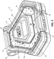
FIG. 3 is a perspective view of the work light with the light unit in a collapsed position. -
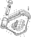
FIG. 4 is a perspective view of the hazard light with the light unit in the collapsed position. -
FIG. 5A is a side view of the light unit in the collapsed position. -
FIG. 5B is a schematic view of the light unit illustrating a plurality of deployed positions. -
FIG. 6 is a partial exploded view of a portion of the light unit and a battery for the light unit. -
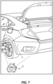
FIG. 7 is a perspective view of the light unit used in an exemplary application. -
FIG. 8 is a perspective view of the light unit used in another exemplary application. -
FIG. 9 is a perspective view of the light unit used in a further exemplary application. -
FIG. 10 is a perspective view of the light unit used in yet another exemplary application. - Before any examples of the disclosure are explained in detail, it is to be understood that the disclosure is not limited in its application to the details of construction and the arrangement of components set forth in the following description or illustrated in the following drawings. The disclosure is capable of other examples and of being practiced or of being carried out in various ways. Also, it is to be understood that the phraseology and terminology used herein is for the purpose of description and should not be regarded as limiting.
- The detailed description uses numerical and letter designations to refer to features in the drawings. Like or similar designations in the drawings and description have been used to refer to like or similar parts of the disclosure.
- The singular forms "a," "an," and "the" include plural references unless the context clearly dictates otherwise. The terms "coupled," "fixed," and the like refer to both direct coupling or fixing, as well as indirect coupling or fixing through one or more intermediate components or features, unless otherwise specified herein. As used herein, the terms "includes," "including," "has," "having" or any other variation thereof, are intended to cover a non-exclusive inclusion. For example, a process, method, article, or apparatus that comprises a list of features is not necessarily limited only to those features but may include other features not expressly listed or inherent to such process, method, article, or apparatus. Further, unless expressly stated to the contrary, "or" refers to an inclusive- or and not to an exclusive- or. For example, a condition A or B is satisfied by any one of the following: A is true (or present) and B is false (or not present), A is false (or not present) and B is true (or present), and both A and B are true (or present).
- Benefits, other advantages, and solutions to problems are described below with regard to specific examples. However, the benefits, advantages, solutions to problems, and any feature(s) that may cause any benefit, advantage, or solution to occur or become more pronounced are not to be construed as a critical, required, or essential feature of any or all the claims.
-
FIGS. 1 and2 illustrate alight unit 10 including awork light 14, ahazard light 18, ahinge 22 that pivotably couples thework light 14 and thehazard light 18 together, and auser interface 26 that controls operation of thework light 14 and thehazard light 18. With reference toFIG. 8 , thelight unit 10 may be used, for example, alongside a vehicle 8 (e.g., adjacent or on a roadside or in a parking structure) to illuminate in a direction of thevehicle 8 as well as to illuminate in another direction (e.g., the opposite direction) and to indicate a hazard for the stoppedvehicle 8. - As illustrated in
FIGS. 1 and3 , thework light 14 includes a work light housing, orframe 30, and awork light fixture 34 supported by thework light frame 30. The illustratedwork light frame 30 is polygonally-shaped and has an overall triangular profile with a first plurality offrame segments frame segments first frame segments work light frame 30. Thesecond frame segments first frame segments work light fixture 34 is positioned between (e.g., in the center of) theframe segments 38a-38c, 42a-42c and is supported by a plurality ofsupport segments support segments 46a-46c extends from a corresponding one of thesecond frame segments work light fixture 34 to support thework light fixture 34. Thework light frame 30 defines a plurality ofapertures work light frame 30 defines threeapertures apertures work light fixture 34, one of thefirst frame segments support segments apertures light unit 10 by one of thefirst frame segments light unit 10. In the illustrated example, a portion of thefirst frame segment 38c positioned opposite from thehinge 22 is cutout such that thefirst frame segment 38c positioned opposite from thehinge 22 may operate as a handle or grip for carrying thelight unit 10. Theapertures light unit 10 from a height relative to a workspace, as will be described in more detail. - In the illustrated example, the
work light frame 30 is formed of a high-strength polymer material. In the illustrated example, the polymer material is formed of a combination of polycarbonate (PC) polymers and acrylonitrile butadiene styrene (ABS) polymers. In other examples, the polymer material may additionally or alternatively include a polyamideimide (PAI) polymer, a polyether ether ketone (PEEK) polymer, a high-density polyethylene (HDPE) polymer, or another similar polymer. In some examples, thework light frame 30 may be formed of a combination of materials including multiple polymers and other materials, such as metals. Thework light frame 30 is also formed with an internal structural design that strengthens thework light frame 30. Specifically, the internal structural design includes forming thework light frame 30 with relatively thicker outer walls and thicker internal ribs than a typical polymer frame. As such, the material and the internal structural design of thework light frame 30 advantageously provide thework light 14 with a drop resistance of up to at least six feet and a crush resistance of at least 10,000 lbs. That is, the material and the internal structural design of thework light frame 30 may inhibit breakages and failure from unintentional drops and unintentional crushing from, for example, drops of thelight unit 10 in which thelight unit 10 falls up to six feet and/or crushing from a vehicle driving over thework light 14. Additionally, thework light frame 30 may be manufactured according to a system-level Ingress Protection Code (i.e. IP Code) such that thework light frame 30 has an IP Code of 55 (i.e. a solid IP Code of 5 and a liquid IP code of 5). At a solid IP Code of 5, thework light frame 30 inhibits dust ingress from interfering with the internal electrics of thework light 14. At a liquid IP Code of 5, thework light frame 30 is protected against low pressure jets of water applied to thework light 14. - The
work light fixture 34 includes a work light printed circuit board (PCB) 58, a first plurality of light emitting diodes (LEDs) 62, and afirst lens 66 positioned downstream of thefirst LEDs 62 along a first light emitting direction A1. Thework light fixture 34 has an outer periphery that is roughly identical, but scaled down in size, to an outer periphery of thework light frame 30 such that thework light fixture 34 fits between theframe segments 38a-38c, 42a-42c. Each of thework light PCB 58, thefirst LEDs 62, and thefirst lens 66 is supported within the outer periphery of thework light fixture 34. Thefirst LEDs 62 are positioned on thework light PCB 58. Thefirst LEDs 62 are configured to receive electricity from thework light PCB 58 and emit white light through thefirst lens 66 along the first light emitting direction A1 when thework light 14 is turned on. The first light emitting direction A1 extends perpendicularly to thefirst lens 66. Thefirst LEDs 62 are arranged on thework light PCB 58 such that thefirst LEDs 62 are configured to emit light in 360 degrees around the periphery of thework light 14 along the first light emitting direction A1. In the illustrated example, thefirst LEDs 62 are configured to emit 500 lumens of light output. In some examples, thefirst LEDs 62 may be configured to emit more lumens of light output. Additionally, thefirst LEDs 62 are configured to emit light that is visible for up to at least one mile away from thework light 14. - As illustrated in
FIGS. 2 and4 , thehazard light 18 includes a hazard light housing, orframe 70, and a hazard light fixture 74. The illustratedhazard light frame 70 is polygonally-shaped and has an overall triangular profile with afirst portion 70a and asecond portion 70b. In the illustrated example, thefirst portion 70a and thesecond portion 70b are formed together. For example, thefirst portion 70a and the second 70b may be formed with a manufacturing process such as injection molding. In some example, thefirst portion 70a and thesecond portion 70b may be formed separately and secured to one another. Thefirst portion 70a has an outer periphery that is roughly identical to an outer periphery of thework light frame 30. Thesecond portion 70b is positioned at the center of thefirst portion 70a and is shaped substantially similarly to thework light fixture 34. As such, thesecond portion 70b has an outer periphery that is roughly identical, but scaled down in size, to the outer periphery of thefirst portion 70a such that thesecond portion 70b fits within the outer periphery of thefirst portion 70a. Thefirst portion 70a and thesecond portion 70b define achannel 76 that is polygonally-shaped and has an overall triangular profile between thefirst portion 70a and thesecond portion 70b. In the illustrated example, thehazard light frame 70 is formed of the same material and the same internal structural design as thework light frame 30. As such, thehazard light frame 70 advantageously provides thehazard light 18 with drop resistance of up to six feet and crush resistance of at least 10,000 lbs. Additionally, thehazard light 18 may be manufactured according system-level IP Code with an IP rating of 55 (i.e. a solid IP Code of 5 and a liquid IP Code of 5). - The hazard light fixture 74 is installed within the
channel 76 defined between thefirst portion 70a and thesecond portion 70b of thehazard light frame 70. The hazard light fixture 74 includes ahazard light PCB 78, a second plurality ofLEDs 82, and asecond lens 86 positioned downstream of thesecond LEDs 82 along a second light emitting direction A2. Thehazard light PCB 78 is triangularly shaped. In the illustrated example, thesecond portion 70b of thehazard light frame 70 extends through the center of thehazard light PCB 78 such that thehazard light PCB 78 is positioned within thechannel 76 between thefirst portion 70a and thesecond portion 70b of thehazard light frame 70. Thesecond LEDs 82 are positioned on thehazard light PCB 78. Thesecond LEDs 82 are configured to receive electricity from thehazard light PCB 78 and emit red light through thesecond lens 86 along the second light emitting direction A2 when thehazard light 18 is turned on. The second light emitting direction A2 extends perpendicularly to thesecond lens 86. Thesecond LEDs 82 are arranged on thehazard light PCB 78 such that thesecond LEDs 82 are configured to emit light in 360 degrees around the periphery of thehazard light 18 along the second light emitting direction A2. Additionally, thesecond LEDs 82 are configured to emit light that is visible for up to at least one mile from thehazard light 18. - The
light unit 10 may additionally include magnets in one or both of thework light 14 and thehazard light 18. Specifically, the magnets may be supported within one or both of thework light frame 30 and thehazard light frame 70. The magnets may assist with mounting thelight unit 10 to a surface. For example, the magnets in thelight unit 10 may be placed in magnetic engagement with a metal surface to secure thelight unit 10 to the metal surface. - With reference to
FIGS. 1 and2 , thehinge 22 includes a worklight hinge portion 90 and a hazardlight hinge portion 94. The worklight hinge portion 90 and the hazardlight hinge portion 94 cooperatively define a cylindrical body. The worklight hinge portion 90 extends from thework light frame 30 and provides the forward and rearward end of the cylindrical body. The hazardlight hinge portion 94 extends from thehazard light frame 70 and extends between the forward and rearward end of the cylindrical body provided by the worklight hinge portion 90. Thehinge 22 enables thework light 14 and thehazard light 18 to pivot relative to one another. Specifically, as illustrated inFIGS. 5A and5B , thehinge 22 allows thework light 14 and thehazard light 18 to pivot to adjust thelight unit 10 between a collapsed or storage position (as illustrated inFIG. 5A ) and a plurality of deployed positions (e.g., as illustrated inFIG. 5B ). In the storage position, thework light 14 and thehazard light 18 are in a back-to-back arrangement where each of the outer profiles of thework light 14 and thehazard light 18 are substantially aligned. - For the sake of brevity, the plurality of deployed positions of the
light unit 10 is described with respect to positions in which thehazard light 18 is pivoted relative to thework light 14. It is understood that the plurality of deployed positions also includes positions in which thework light 14 is pivoted relative to thehazard light 18. As illustrated inFIG. 5B , thelight unit 10 is in a full-pivot position. In the full-pivot position, thehazard light 18 is pivoted 200 degrees relative to thework light 14. As such, the first light emitting direction A1 and the second light emitting direction A2 may intersect when thelight unit 10 is in the full pivot position. In some examples, thehinge 22 may allow for additional pivoting such that thehazard light 18 is pivotable by more than 200 degrees relative to thework light 14. Thehazard light 18 is infinitely adjustable between the collapsed position (FIG. 5A ) and the full-pivot position such that thelight unit 10 may be adjusted to a plurality of intermediate positions.FIG. 5B illustrates three exemplary intermediate positions B1, B2, B3. In a firstintermediate position B 1, thehazard light 18 is pivoted less than 90 degrees relative to thework light 14. More specifically, thehazard light 18 is pivoted roughly 70 degrees relative to thework light 14. In a second intermediate position B2, thehazard light 18 is pivoted roughly 90 degrees relative to thework light 14. In a third intermediate position B3, thehazard light 18 is pivoted between 90 degrees and 200 degrees relative to thework light 14. As such, thelight unit 10 may be positioned according to user preference in any deployed position in which the angle between thework light 14 and thehazard light 18 is between 0 and 200 degrees. - With reference to
FIG. 6 , the cylindrical body of thehinge 22 defines a cavity shaped to receive abattery 98 that provides power to thework light PCB 58 for illumination of the first LEDs 62 (FIG. 3 ) and to thehazard light PCB 78 for illumination of the second LEDs 82 (FIG. 4 ). Thehinge 22 further includes acap 102 that is threadedly coupled to the cylindrical body. Thecap 102 may be selectively removed from the body to allow access to the cavity for insertion and removal of thebattery 98. Thebattery 98 may include lithium ion (Li-ion) cells. In alternate examples, thebattery 98 may be of a different chemistry (e.g., nickel-cadmium (NiCa or NiCad), nickel-hydride, and the like). Thebattery 98 has a 24-hour life such that thelight unit 10 may be powered for 24 continuous hours solely by thebattery 98. In the illustrated example, thebattery 98 is a 4-volt battery. In alternate examples, the capacity of thebattery 98 may vary. Thebattery 98 may include a charging port that allows thebattery 98 to be recharged by an external power source when thebattery 98 is removed from the cavity of the cylindrical body. In some examples, thebattery 98 may be rechargeable while thebattery 98 is positioned within the body. Thebattery 98 additionally includes aUSB port 106 that may function as a power outlet to allow thebattery 98 to be used as a portable power source separately from thelight unit 10. For example, a USB cord may be plugged into theUSB port 106 of thebattery 98 to charge a mobile phone. - As illustrated in
FIGS. 4 and6 , theuser interface 26 is supported on and in thesecond portion 70b of thehazard light frame 70 and includes auser interface PCB 110, awork light actuator 114, and ahazard light actuator 118. Theuser interface PCB 110 is substantially enclosed by thesecond portion 70b of thehazard light frame 70 and is electrically connected to the work light PCB 58 (FIG. 3 ), thehazard light PCB 78, and thebattery 98 viawiring 122. Each of thework light actuator 114 and thehazard light actuator 118 is positioned on theuser interface PCB 110 and extends through thesecond portion 70b of thehazard light frame 70. Thework light actuator 114 is actuatable to turn on and adjust a work light mode of thework light 14. Thehazard light actuator 118 is actuatable to turn on and adjust a hazard light mode of thehazard light 18. In the illustrated example, thework light actuator 114 and thehazard light actuator 118 are independent of each other such that actuation of thework light actuator 114 or thehazard light actuator 118 does not affect actuation of the other of thework light actuator 114 or thehazard light actuator 118. As such, thework light 14 and thehazard light 18 may be illuminated independent of one another. Thework light actuator 114 and thehazard light actuator 118 may be actuated at the same time such that thework light 14 and thehazard light 18 are illuminated at the same time. - In the illustrated example, the
work light 14 has at least three different work light modes, and thehazard light 18 has at least three different hazard light modes. The at least three work light modes include a low intensity mode, a medium intensity mode, and a high intensity mode. A user may switch between the work light modes by pressing, or actuating, thework light actuator 114. Specifically, actuation (e.g., pressing the actuator 114 toward the user interface PCB 110) of thework light actuator 114 when thework light 14 is off switches thework light 14 to the low intensity mode. Actuation thework light actuator 114 again (i.e., a second time) switches thework light 14 from the low intensity mode to the medium intensity mode. Actuation of thework light actuator 114 once more (i.e., a third time) switches thework light 14 from the medium intensity mode to the high intensity mode. When thework light 14 is in the high intensity mode, actuation of the work light actuator 114 (i.e., a fourth time) turns thework light 14 off. - In the illustrated example, the three hazard light modes include a steady mode, a flash mode, and a tracer mode. In the steady mode, light emitted from the
hazard light 18 is constant. In the flash mode, light emitted from thehazard light 18 intermittently flashes (e.g., in a pattern). In the tracer mode, light emitted from the hazard light 18 loops around thesecond portion 70b of thehazard light frame 70. That is, each of the second LEDs (FIG. 4 ) are illuminated in succession or sequentially (and thereafter turned off) along a clockwise or counterclockwise path such that the emitted light appears to move along a path. A user may switch thehazard light 18 between the hazard light modes by pressing, or actuating, thehazard light actuator 118 as similarly described with respect to thework light actuator 114. Specifically, actuation (e.g., pressing the actuator 118 toward the user interface PCB 110) of thehazard light actuator 118 when thehazard light 18 is off switches thehazard light 18 to the steady mode. Actuation of thehazard light actuator 118 again (i.e., a second time) switches the hazard light 18 from the steady mode to the flash mode. Actuation of thehazard light actuator 118 once more (i.e., a third time) switches the hazard light 18 from the flash mode to the tracer mode. When thehazard light 18 is in the tracer mode, actuation of the hazard light actuator 118 (i.e., a fourth time) turns thehazard light 18 off. - Due to the
work light actuator 114 and thehazard light actuator 118 being independently operable, thelight unit 10 may be set in 15 different modes. The 15 different modes include every combination of the following: thework light 14 turned off with thehazard light 18 in each of the three hazard light modes, thehazard light 18 turned off with thework light 14 in each of the three work light modes, thework light 14 in the low intensity mode with thehazard light 18 in each of the three hazard light modes, thework light 14 in the medium intensity mode with thehazard light 18 in each of the three hazard light modes, and thework light 14 in the high intensity mode with thehazard light 18 in each of the three hazard light modes. For example, in a first mode of thelight unit 10, thework light 14 is turned off and thehazard light 18 is in the flash mode. In a second mode of thelight unit 10, thework light 14 is in the high intensity mode, and thehazard light 18 is turned off. In a third mode, thework light 14 is in the high intensity mode, and thehazard light 18 is in the tracer mode. It can be appreciated that the first mode, the second mode, and the third mode are provided as examples and are not indicative of a primary mode or use of thelight unit 10. In some examples, thelight unit 10 may be operable in fewer than or more than 15 modes. For example, thework light 14 may include additional intensity modes. In one or more example, thework light 14 may include fewer intensity modes. In another example, thework light 14 may be operable in a flash mode in which thefirst LEDs 62 flash intermittently. In one or more example, thehazard light 18 may have additional modes (e.g., modes of different light intensities). - The
light unit 10 may be used in multiple applications. In one application, with reference toFIG. 7 , thelight unit 10 may be utilized alongside avehicle 8. Specifically, thelight unit 10 may be utilized to assist (e.g., by providing illumination) with performing maintenance on avehicle 8 on a roadside while indicating a hazard to drivers on the road passing by. In this application, with reference toFIGS. 5B and7 , thehazard light 18 may be pivoted about thehinge 22 to the first intermediate position B1. In the first intermediate position B1, thehazard light 18 is pivoted roughly 70 degrees about thehinge 22 relative to thework light 14 such that thework light 14 and thehazard light 18 may cooperatively support thelight unit 10 relative to a ground surface to allow thelight unit 10 to stand relative to the ground surface. Once thelight unit 10 is placed on the ground surface, a user may set thelight unit 10 in any of the 15 different modes through actuation of thework light actuator 114 and thehazard light actuator 118. For example, a user may set thelight unit 10 in the third mode of thelight unit 10, as described above, in which thework light 14 is in the high intensity mode to illuminate thevehicle 8, and thehazard light 18 is in the flash mode to provide a hazard indication to drivers on the road passing thevehicle 8. - In another application, as illustrated in
FIG. 8 , thelight unit 10 may be used in association with atrunk 130 of thevehicle 8. For example, atrunk door 130a of thetrunk 130 may be raised to allow access to thetrunk 130. With thetrunk door 130a raised, a user may mount thelight unit 10 to thetrunk door 130a. In this application, with reference toFIGS. 5B and8 , thehazard light 18 may be pivoted to the first intermediate position B1 in which thehazard light 18 is pivoted less than 90 degrees relative to thework light 14. With thelight unit 10 in the first intermediate position B1, thelight unit 10 may be mounted to thetrunk door 130a such that thetrunk door 130a extends between thework light 14 and thehazard light 18. As illustrated inFIG. 8 , thelight unit 10 is mounted such that thehazard light 18 faces rearward of the vehicle 8 (e.g., toward a user accessing the trunk 130) to indicate a hazard, for example, to drivers on a road passing by. Thelight unit 10 may also be mounted such that thework light 14 faces rearward of the vehicle 8 (e.g., toward a user accessing the trunk 130) to illuminate thetrunk 130 and an area rearward of thevehicle 8. In examples of thelight unit 10 in which thelight unit 10 includes magnets, the magnets in thelight unit 10 may engage an outer surface of thetrunk door 130a to magnetically attach thelight unit 10 to thetrunk door 130a. - In a further application, as illustrated in
FIG. 9 , thelight unit 10 may be used in association with ahood 134 of thevehicle 8. For example, thehood 134 of thevehicle 8 may be raised to allow access to anengine 138 of thevehicle 8. With thehood 134 raised, a user may mount thelight unit 10 to vehicle by placing thelight unit 10 on, for example, awindshield 142 of thevehicle 8. In this application, with reference toFIGS. 5B and9 , thehazard light 18 may be pivoted to the second intermediate position B2 in which thehazard light 18 is pivoted roughly 90 degrees relative to thework light 14. Thelight unit 10 may then be placed on thewindshield 142 of thevehicle 8 such that thework light 14 is oriented to emit light directly onto a desired portion of theengine 138 of thevehicle 8. In some instances, thehazard light 18 may be pivoted more or less than 90 degrees to allow a user to set thelight unit 10 such that light is emitted as desired relative to theengine 138. - In yet another application, as illustrated in
FIG. 10 , thelight unit 10 may be used in a non-vehicular workspace. Examples of a non-vehicular workspaces include, but are not limited to, a woodworking stand, an automotive body shop, and construction sites. In the non-vehicular workspace, with reference toFIGS. 1 and10 , thelight unit 10 may be used in the collapsed position (FIG. 5A ), the full pivot position (FIG. 5B ), and an infinite number of deployed positions between the collapsed position (FIG. 5A ) and the full pivot position (FIG. 5B ). Specifically, thelight unit 10 may be adjusted to any position in which the first light emitting direction A1 extends at least partially through the non-vehicular workspace such that the first LEDs 62 (FIG. 3 ) emit light directly onto the workspace. In some applications, thelight unit 10 may be hung from a height relative to the workspace. For example, a cord may be fed through one of the plurality ofapertures work light 14 and secured to an overhead beam or pipe to suspend thelight unit 10 at a desired height. Once thelight unit 10 is positioned in a desired orientation, thelight unit 10 may be set in one of the 15 different modes of operation. In the non-vehicular workspace, there may be no need to indicate a hazard, so thelight unit 10 may, for example, be set in a mode in which thehazard light 18 is off. - Although applications of the
light unit 10 have been described with regard to thevehicle 8 and non-vehicular workspace s5b, it is understood that thelight unit 10 may be used in any number of applications and workspaces in which illumination is desired. Specifically, thelight unit 10 may be adjusted to any deployed position (e.g., illustrated inFIG. 5B ) and set to any of the 15 different modes based on situational needs of a user. For example, other uses of thelight unit 10 include, but are not limited to, oversized load warnings, recreational uses, emergency preparedness situations, long-haul trucking, towing, and emergency services. In oversized load warnings, thelight unit 10 may be used to indicate a hazard from the rear of a vehicle while a user operates the vehicle to tow or haul large loads. In recreational uses, thelight unit 10 may be used to illuminate, for example, a campsite or tent. In emergency preparedness applications, thelight unit 10 may used to illuminate an area in situations in which power is lost in a home or building. In long-haul trucking applications, multiplelight units 10 may set up in succession along a distance from a stopped semi-truck to provide a hazard indication that is visible from further away than through use of asingle light unit 10. In towing application, thelight unit 10 may be set up to provide a hazard indication for a tow truck as a tow truck operator tows a vehicle, for example, on the side of the road. In emergency services applications, maintenance and construction workers may set up light units 10 a distance from a service area to provide a hazard indication of the service area. Thebattery 98 of thelight unit 10 may also be separately used to provide power to other electrical systems than thework light 14 and thehazard light 18. For example, thebattery 98 may be used as a portable power source to provide power to charge a mobile phone. - While the disclosure has been presented with respect to a limited number of examples, those skilled in the art, having benefit of this disclosure, will appreciate other examples may be devised which do not depart from the scope of the present disclosure.
-
Clause 1. A light unit comprising: a work light configured to emit light in a first direction; a hazard light configured to emit light in a second direction; a hinge coupled between the work light and the hazard light such that the work light and the hazard light are independently rotatable relative to each other about the hinge from a storage position to a deployed position; a user interface disposed on the hazard light, the user interface including a work light actuator engageable to actuate the work light and a hazard light actuator engageable independent from the work light actuator to actuate the hazard light. - Clause 2. The light unit of
clause 1, wherein the hazard light is rotatable approximately 200 degrees relative to the work light from the storage position. - Clause 3. The light unit of clause 2, wherein the storage position is defined by the work light and the hazard light in a back-to-back arrangement.
- Clause 4. The light unit of
clause 1, wherein the hinge defines a cavity configured to receive a battery configured to provide power to each of the work light and to the hazard light. - Clause 5. The light unit of
clause 1, wherein the work light actuator includes at least two work light modes, and wherein the hazard light actuator includes at least two hazard light modes separate from the work light modes. - Clause 6. The light unit of clause 5, wherein the at least two work light modes include two or more of a low intensity mode, a medium intensity mode, and a high intensity mode.
- Clause 7. The light unit of clause 5, wherein the at least two hazard light modes include two or more of a steady mode, a flash mode, and a tracer mode.
-
Clause 8. The light unit ofclause 1, wherein the work light includes a first frame and the hazard light includes a second frame different from the first frame, and wherein at least one of the first frame and the second frame includes a magnet. -
Clause 9. The light unit ofclause 1, wherein only the work light includes an aperture configured to be gripped by a user. -
Clause 10. The light unit ofclause 1, wherein the hazard light further includes a circuit board electrically coupled to the work light and the hazard light, wherein the circuit board is configured to control an output of each of the work light and the hazard light. - Clause 11. The light unit of
clause 10, wherein the circuit board further comprises a user interface including a work light actuator and a hazard light actuator disposed only on the work light or the hazard light. - Clause 12. The light unit of clause 11, wherein the circuit board is a first circuit board and the light unit further comprises a second circuit board electrically coupled between first circuit board and the work light and a third circuit board electrically coupled between the first circuit board and the hazard light.
- Clause 13. A light unit comprising: a work light including a first hinge portion through which a pivot axis extends; and a hazard light including a second hinge portion rotatably coupled to the first hinge portion about the pivot axis; wherein the first hinge portion and the second hinge portion cooperatively define a cavity configured to receive a power source to power each of the work light and the hazard light.
-
Clause 14. The light unit of clause 13, wherein each of the work light and hazard light is pivotable about the pivot axis up to approximately 200 degrees from a storage position in which the work light and the hazard light are in a back-to-back arrangement. - Clause 15. The light unit of clause 13, further comprising a first circuit board electrically coupled to the work light and a second circuit board coupled to the hazard light.
- Clause 16. The light unit of clause 15, wherein the first circuit board includes a user interface including a work light actuator and a hazard light actuator disposed only on the work light or the hazard light.
- Clause 17. The light unit of clause 15, further comprising a second circuit board electrically coupled between the first circuit board and the work light and a third circuit board electrically coupled between the first circuit board and the hazard light.
-
Clause 18. A light unit comprising: a work light fixture including: a work light frame defining a plurality of frame segments and at least one aperture formed between the frame segments; a first LED disposed at a center portion of the frame segments; and a first hinge portion coupled to at least one of the plurality of frame segments; and a hazard light fixture including: a hazard light frame having a second hinge portion pivotably coupled to the first hinge portion, the hazard light frame further having a first portion defining an outer periphery of the hazard light frame and a second portion spaced from the first portion toward a center of the hazard light frame; a channel defined between the first portion and the second portion; a second LED disposed within the channel; and a circuit board supported by the second portion, the circuit board configured to control an output of each of the first LED and the second LED; wherein the first hinge portion and the second hinge portion cooperatively define a cylindrical body configured to receive a power source. - Clause 19. The light unit of
clause 18, wherein the circuit board includes a user interface having a work light actuator and a hazard light actuator that are independently actuatable to control the work light and the hazard light. - Clause 20. The light unit of clause 19, wherein the work light actuator is configured to switch the work light between at least two different work light modes, and wherein the hazard light actuator is configured to switch the hazard light between at least two different hazard light modes.
Claims (15)
- A light unit comprising:a work light configured to emit light in a first direction;a hazard light configured to emit light in a second direction;a hinge coupled between the work light and the hazard light such that the work light and the hazard light are independently rotatable relative to each other about the hinge from a storage position to a deployed position;a user interface coupled to the hazard light and including a work light actuator engageable to actuate the work light and a hazard light actuator engageable independent from the work light actuator to actuate the hazard light.
- The light unit of claim 1, wherein the hazard light is rotatable approximately 200 degrees relative to the work light from the storage position; and/or
wherein the storage position is defined by the work light and the hazard light in a back-to-back arrangement. - The light unit of claim 1, wherein the hinge defines a cavity configured to receive a battery configured to provide power to each of the work light and to the hazard light.
- The light unit of claim 1, wherein the work light actuator includes at least two work light modes, and wherein the hazard light actuator includes at least two hazard light modes separate from the work light modes; and/orwherein the at least two work light modes include two or more of a low intensity mode, a medium intensity mode, and a high intensity mode; and/orwherein the at least two hazard light modes include two or more of a steady mode, a flash mode, and a tracer mode.
- The light unit of claim 1, wherein the work light includes a first frame and the hazard light includes a second frame different from the first frame, and wherein at least one of the first frame and the second frame includes a magnet.
- The light unit of claim 1, wherein only the work light includes an aperture configured to be gripped by a user.
- The light unit of claim 1, wherein the hazard light further includes a circuit board electrically coupled to the work light and the hazard light, wherein the circuit board is configured to control an output of each of the work light and the hazard light; and/orwherein the circuit board further comprises a user interface including a work light actuator and a hazard light actuator disposed only on the work light or the hazard light; and/orwherein the circuit board is a first circuit board and the light unit further comprises a second circuit board electrically coupled between first circuit board and the work light and a third circuit board electrically coupled between the first circuit board and the hazard light.
- The light unit of claim 1, wherein the work light includes a first hinge portion through which a pivot axis extends and the hazard light includes a second hinge portion rotatably coupled to the first hinge portion about the pivot axis, and wherein the first hinge portion and the second hinge portion cooperatively define a cavity configured to receive a power source to power each of the work light and the hazard light.
- The light unit of claim 8, wherein each of the work light and hazard light is pivotable about the pivot axis up to approximately 200 degrees from a storage position in which the work light and the hazard light are in a back-to-back arrangement.
- The light unit of claim 8, further comprising a first circuit board electrically coupled to the work light and a second circuit board coupled to the hazard light.
- The light unit of claim 10, wherein the first circuit board includes a user interface including a work light actuator and a hazard light actuator disposed only on the work light or the hazard light.
- The light unit of claim 10, further comprising a second circuit board electrically coupled between the first circuit board and the work light and a third circuit board electrically coupled between the first circuit board and the hazard light.
- A light unit comprising:a work light fixture including:a work light frame defining a plurality of frame segments and at least one aperture formed between the frame segments;a first LED disposed at a center portion of the frame segments; anda first hinge portion coupled to at least one of the plurality of frame segments; and a hazard light fixture including:a hazard light frame having a second hinge portion pivotably coupled to the first hinge portion, the hazard light frame further having a first portion defining an outer periphery of the hazard light frame and a second portion spaced from the first portion toward a center of the hazard light frame;a channel defined between the first portion and the second portion;a second LED disposed within the channel; anda circuit board supported by the second portion, the circuit board configured to control an output of each of the first LED and the second LED;wherein the first hinge portion and the second hinge portion cooperatively define a cylindrical body configured to receive a power source.
- The light unit of claim 13, wherein the circuit board includes a user interface having a work light actuator and a hazard light actuator that are independently actuatable to control the work light and the hazard light.
- The light unit of claim 14, wherein the work light actuator is configured to switch the work light between at least two different work light modes, and wherein the hazard light actuator is configured to switch the hazard light between at least two different hazard light modes.
Applications Claiming Priority (1)
| Application Number | Priority Date | Filing Date | Title |
|---|---|---|---|
| US202463617108P | 2024-01-03 | 2024-01-03 |
Publications (1)
| Publication Number | Publication Date |
|---|---|
| EP4582735A1 true EP4582735A1 (en) | 2025-07-09 |
Family
ID=94173333
Family Applications (1)
| Application Number | Title | Priority Date | Filing Date |
|---|---|---|---|
| EP25150239.9A Pending EP4582735A1 (en) | 2024-01-03 | 2025-01-03 | Hazard light |
Country Status (4)
| Country | Link |
|---|---|
| US (1) | US12638145B2 (en) |
| EP (1) | EP4582735A1 (en) |
| CN (1) | CN120260188A (en) |
| AU (1) | AU2025200030A1 (en) |
Families Citing this family (2)
| Publication number | Priority date | Publication date | Assignee | Title |
|---|---|---|---|---|
| USD1102641S1 (en) * | 2023-12-20 | 2025-11-18 | Milwaukee Electric Tool Corporation | Work light |
| US12705961B1 (en) * | 2024-02-16 | 2026-08-11 | Michael Bernard Thomas | System and method for providing an illuminating, visual indication of a specific physical location and situation |
Citations (6)
| Publication number | Priority date | Publication date | Assignee | Title |
|---|---|---|---|---|
| JP2007311055A (en) * | 2006-05-16 | 2007-11-29 | Midori Denshi Kk | Portable lighting device |
| WO2010131172A2 (en) * | 2009-05-15 | 2010-11-18 | Koninklijke Philips Electronics N.V. | Lighting device |
| KR101159295B1 (en) * | 2010-12-17 | 2012-06-22 | (주)씨티엘 | Portable illumination device and safety unit for vehicle using the same |
| CN204387915U (en) * | 2014-12-30 | 2015-06-10 | 广州同明太阳能科技有限公司 | A kind of angle adjustment mechanism of Portable LED lamp |
| US10072829B1 (en) * | 2016-01-29 | 2018-09-11 | Cooper Technologies Company | Portable light |
| US20190353332A1 (en) * | 2018-05-21 | 2019-11-21 | E. Mishan & Sons, Inc. | Multi-Function Work Light |
Family Cites Families (33)
| Publication number | Priority date | Publication date | Assignee | Title |
|---|---|---|---|---|
| DE3028219C2 (en) | 1980-07-25 | 1983-01-13 | Herbert 6232 Bad Soden Böse | Warning lamp |
| US2080859A (en) | 1933-12-14 | 1937-05-18 | Drapak Otto | Dovetail milling machine |
| US5221003A (en) | 1992-05-20 | 1993-06-22 | Chang Hsiu Wei | Portable travel box with multiple traffic purposes |
| GB2341408A (en) | 1998-09-11 | 2000-03-15 | Wang Shiunn Terny | Portable hazard-warning device |
| CA2296859A1 (en) | 2000-01-21 | 2001-07-21 | Hung-Ming Shih | Warning device for motor vehicle |
| US6839001B1 (en) | 2002-08-09 | 2005-01-04 | Walter E. Bonin | Safety strobe light |
| US6928951B2 (en) | 2003-06-02 | 2005-08-16 | Sunny En Liung Huang | Foldable triangular caution device |
| US20040237877A1 (en) | 2003-06-02 | 2004-12-02 | Huang Sunny En Liung | Foldable caution device with bag |
| US6899441B2 (en) | 2003-08-04 | 2005-05-31 | Hsiu Chin Chen | Multifunction warning device |
| US7011423B2 (en) | 2003-08-04 | 2006-03-14 | Hsiu Chin Chen | Multifunction warning device |
| GB2415728A (en) | 2004-06-28 | 2006-01-04 | Hsiu Chin Chen | Multifunction warning device |
| DE202005009815U1 (en) | 2005-06-22 | 2005-10-13 | Friedrich, Peter | Folding traffic warning triangle for protecting vehicle stopped on road has high-visibility blinking light supplied with current from battery in metal foot portion or base |
| CN100569558C (en) | 2008-05-07 | 2009-12-16 | 李政文 | Electric concealed type striking caution board for vehicle |
| US9046231B2 (en) * | 2009-03-13 | 2015-06-02 | Cooper Technologies Company | Folding worklight with attachment mechanism |
| US8430529B2 (en) * | 2009-03-13 | 2013-04-30 | Cooper Technologies Company | Folding worklight with attachment mechanism |
| US7954980B2 (en) * | 2009-03-13 | 2011-06-07 | Cooper Technologies Company | Folding rechargeable worklight |
| US8365918B1 (en) | 2010-01-19 | 2013-02-05 | Andino Jose E | Emergency notification flashing system |
| US8742917B2 (en) | 2011-01-24 | 2014-06-03 | Chang-Hsien Ho | Warning triangle structure |
| KR101282241B1 (en) | 2011-05-02 | 2013-07-10 | 청주대학교 산학협력단 | Traffic safety signboard for portable |
| WO2013148314A1 (en) | 2012-03-29 | 2013-10-03 | Sylo Systems, Llc | Portable sign |
| US9545878B2 (en) | 2012-03-29 | 2017-01-17 | Sylo Systems, Llc | Portable Sign |
| CN102637394B (en) | 2012-04-12 | 2014-05-14 | 张佳俊 | Remote-control movable tripod |
| CN104797459B (en) | 2012-11-30 | 2017-06-13 | 金泰院 | Self-opening LED safety pyramid |
| DE202014103184U1 (en) | 2014-07-11 | 2014-08-06 | Adolf Nissen Elektrobau Gmbh + Co. Kg | Pyramidal fold signal |
| CN204759967U (en) | 2015-02-06 | 2015-11-11 | 黄明曦 | Multi -functional self -propelled stack LED triangle warning plate |
| GB201507822D0 (en) | 2015-05-07 | 2015-06-17 | Road Safety Designs Ltd | Foldable warning triangle assembly |
| CN105070227A (en) | 2015-08-31 | 2015-11-18 | 刘家德 | Foldable warning triangular frame |
| US9862314B2 (en) | 2016-01-25 | 2018-01-09 | Shanghai Karstone energy technology co., Ltd. | Warning triangle stand |
| GB2554858A (en) | 2016-09-30 | 2018-04-18 | Road Safety Designs Ltd | Foldable warning triangle assembly |
| DE202016007685U1 (en) | 2016-12-20 | 2018-03-21 | GM Global Technology Operations LLC (n. d. Ges. d. Staates Delaware) | Motor vehicle with warning sign |
| GB2559590A (en) | 2017-02-10 | 2018-08-15 | Road Safety Designs Ltd | A warning device for a vehicle |
| JP6999981B2 (en) | 2017-08-07 | 2022-01-19 | ボク キム、ジェ | Emergency call device for vehicles and rear vehicle consideration system equipped with it |
| CN111063278A (en) | 2018-10-16 | 2020-04-24 | 林铭堃 | Vehicle Triangle Warning System |
-
2025
- 2025-01-03 CN CN202510010855.0A patent/CN120260188A/en active Pending
- 2025-01-03 AU AU2025200030A patent/AU2025200030A1/en active Pending
- 2025-01-03 US US19/009,473 patent/US12638145B2/en active Active
- 2025-01-03 EP EP25150239.9A patent/EP4582735A1/en active Pending
Patent Citations (6)
| Publication number | Priority date | Publication date | Assignee | Title |
|---|---|---|---|---|
| JP2007311055A (en) * | 2006-05-16 | 2007-11-29 | Midori Denshi Kk | Portable lighting device |
| WO2010131172A2 (en) * | 2009-05-15 | 2010-11-18 | Koninklijke Philips Electronics N.V. | Lighting device |
| KR101159295B1 (en) * | 2010-12-17 | 2012-06-22 | (주)씨티엘 | Portable illumination device and safety unit for vehicle using the same |
| CN204387915U (en) * | 2014-12-30 | 2015-06-10 | 广州同明太阳能科技有限公司 | A kind of angle adjustment mechanism of Portable LED lamp |
| US10072829B1 (en) * | 2016-01-29 | 2018-09-11 | Cooper Technologies Company | Portable light |
| US20190353332A1 (en) * | 2018-05-21 | 2019-11-21 | E. Mishan & Sons, Inc. | Multi-Function Work Light |
Also Published As
| Publication number | Publication date |
|---|---|
| CN120260188A (en) | 2025-07-04 |
| US20250216040A1 (en) | 2025-07-03 |
| US12638145B2 (en) | 2026-05-26 |
| AU2025200030A1 (en) | 2025-07-17 |
Similar Documents
| Publication | Publication Date | Title |
|---|---|---|
| US20250216040A1 (en) | Hazard light | |
| US11654990B2 (en) | Electric bicycle | |
| US6099141A (en) | Roadside emergency security flashlight | |
| US6756764B2 (en) | Portable jumper system and method | |
| CN205791680U (en) | Automobile emergency power supply with LED panel for warning | |
| US20210387571A1 (en) | Truck storage box with integrated lighting and power | |
| WO2020009756A1 (en) | Modular system | |
| US20050030737A1 (en) | Multifunction warning device | |
| US20210310641A1 (en) | Modular System | |
| US4395696A (en) | Plastic emergency power pack for vehicle trailer | |
| US20080180238A1 (en) | Vehicle signaling device having a remote power source | |
| US20190161926A1 (en) | Life saver device and method | |
| US11047556B2 (en) | Modular system | |
| JP2008213806A (en) | Light emitting diode triangular warning plate | |
| US20050237735A1 (en) | Illuminating mount | |
| US20030043581A1 (en) | Vehicle jack with directable light source | |
| EP1927510A2 (en) | Removable vehicle signaling device | |
| US20080030979A1 (en) | Module for a flashlight or lantern | |
| US20060087836A1 (en) | Portable lighting assembly for automotive vehicle | |
| CN206890140U (en) | A kind of portable emergency warning lamp | |
| CN113063129B (en) | Control method of display lamp | |
| US20050259420A1 (en) | Storage container lighting system | |
| CN222068447U (en) | An emergency warning light for road safety prompts | |
| WO2016028283A1 (en) | Improved vehicle rear-lighting augmentation device for cargo racks and trailers and methods of use | |
| KR101159295B1 (en) | Portable illumination device and safety unit for vehicle using the same |
Legal Events
| Date | Code | Title | Description |
|---|---|---|---|
| PUAI | Public reference made under article 153(3) epc to a published international application that has entered the european phase |
Free format text: ORIGINAL CODE: 0009012 |
|
| STAA | Information on the status of an ep patent application or granted ep patent |
Free format text: STATUS: THE APPLICATION HAS BEEN PUBLISHED |
|
| AK | Designated contracting states |
Kind code of ref document: A1 Designated state(s): AL AT BE BG CH CY CZ DE DK EE ES FI FR GB GR HR HU IE IS IT LI LT LU LV MC ME MK MT NL NO PL PT RO RS SE SI SK SM TR |
|
| STAA | Information on the status of an ep patent application or granted ep patent |
Free format text: STATUS: REQUEST FOR EXAMINATION WAS MADE |
|
| 17P | Request for examination filed |
Effective date: 20260109 |