TECHNICAL FIELD
-
The present application relates to engine cooling systems and controls, control processes, and control systems for engine cooling systems, and related apparatuses, processes, systems, and techniques.
BACKGROUND
-
Controls, control processes, and control systems for cooling systems for engines and controls for such systems suffer from a number of shortcomings including those respecting adjustability in coolant temperature, timeliness and response times in adjusting coolant temperatures, and accuracy in coolant temperature adjustments. As a result, increased emissions from the engine, lower thermal efficiency, and lower fuel efficiency may occur during operation of the engine than would result if these shortcomings were addressed. There remains a significant need for the unique apparatuses, processes, systems, and techniques disclosed herein.
DISCLOSURE OF EXAMPLE EMBODIMENTS
-
For the purposes of clearly, concisely, and exactly describing example embodiments of the present disclosure, the manner, and process of making and using the same, and to enable the practice, making and use of the same, reference will now be made to certain example embodiments, including those illustrated in the figures, and specific language will be used to describe the same. It shall nevertheless be understood that no limitation of the scope of the invention is thereby created, and that the invention includes and protects such alterations, modifications, and further applications of the example embodiments as would occur to one skilled in the art.
SUMMARY
-
Some embodiments include unique cooling system controls for internal combustion engines. Further embodiments include unique apparatuses, systems, and processes including or embodying such controls. Further embodiments, forms, objects, features, advantages, aspects, and benefits shall become apparent from the following description and drawings.
BRIEF DESCRIPTION OF THE DRAWINGS
-
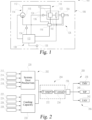
- Fig. 1 is a schematic diagram illustrating certain aspects of an example system for a vehicle including an example cooling system for an internal combustion engine.
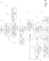
- Fig. 2 is a schematic diagram illustrating certain aspects of example controls for the system of Fig. 1 for controlling coolant temperature.
- Fig. 3 is a schematic diagram illustrating certain aspects of example controls for the system of Fig. 1 for controlling coolant temperature.
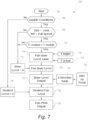
- Fig. 4 is a schematic diagram illustrating certain aspects of an example control process for controlling coolant temperature of the system of Fig. 1 during engine warmup.
- Fig. 5 is a flow diagram illustrating certain aspects of an example control process for controlling a thermal management valve of the cooling system of Fig. 1.
- Fig. 6 is a flow diagram illustrating certain aspects of an example control process for controlling a water pump of the cooling system of Fig. 1.
- Fig. 7 is a graph illustrating certain aspects of an example control process for controlling a cooling fan of the cooling system of Fig. 1.
DETAILED DESCRIPTION OF EXAMPLE EMBODIMENTS
-
With reference to Fig. 1, there is illustrated a vehicle system 100 (also referred to as system 100) including an internal combustion engine 102 and a cooling system 110. Cooling system 110 is configured to supply coolant to various components of engine 102 such as a retarder 104 and/or to other cooled components of engine 102 and/or system 100. In the illustrated embodiment system 100 is configured and provided on a vehicle 106 such as an on-highway vehicle, an off-highway vehicle, or a work vehicle. In other embodiments, engine 102 and cooling system 110 may be provided with other forms, including non-vehicular applications.
-
In the illustrated embodiment, the cooling system 110 includes a coolant for circulation through one or more coolant lines 112 forming one or more cooling loops. For example, a first cooling loop 114 includes a thermal management valve (TMV) 116 and a clutched water (coolant) pump (WP) 118. Cooling system 110 also includes a heat exchanger 120 (such as a radiator) and a clutched cooling fan 122 associated with heat exchanger 120 that is configured to be started and operate at variable speeds to generate and air flow for cooling the coolant. A bypass 124 is provided to bypass heat exchanger 120, such as while TMV 116 is closed to prevent or reduce coolant flow through heat exchanger 120.
-
Cooling system 110 may also include a second cooling loop 126 to provide coolant to retarder 104, at least during operating conditions in which retarder 104 is active. In an embodiment, retarder 104 is coupled to an output shaft of engine 102 to assist in slowing engine 102 and/or vehicle 106 without the use of engine or friction braking. In an embodiment, coolant is provide to second cooling loop 126 through TMV 116, although other arrangements are also contemplated. In other embodiments, retarder 104 is integrated into first cooling loop 114.
-
In an embodiment, TMV 116 is a variable thermostat with a ball valve controlled by an actuator in response to a TMV command from a fully closed (0%) condition to a fully open (100%) condition, and to any position therebetween. In an embodiment, WP 118 is a clutched pump that can run at multiple speeds. For example, WP 118 can run at full speed, at a half speed, or at zero speed in response to a WP 118 output command. In an embodiment, clutched cooling fan 122 is electronically controlled in response to a desired fan level using pulse-width modulation (PWM) to control the output for fan 122 between 0% (fan off) and 100% (fan maximum speed.)
-
System 100 further includes electronic control system (ECS) 130 in communication with engine 102 and cooling system 110 and configured to control one or more aspects of engine 102 and cooling system 110, including controlling operation of TMV 116, WP 118, and fan 122. ECS 130 typically include at least one electronic control unit (ECU) 132 configured to execute operations of ECS 130 as described further herein and, in some embodiment, may include additional ECUs configured to execute operations of ECS 130 as described further herein.
-
ECS 130 includes one or more sensors, which may be physical sensors, virtual sensors, and/or hybrid physical-virtual sensors. In an embodiment, the one or more sensors include a coolant temperature sensor 134. The one or more sensors may also include one or more heat production sensors 136 such as, for example, an engine load sensor, an accelerator pedal sensor, a retarder sensor, and/or a grade sensor to provide parameters used to determine a heat production value of system 100. The one or more sensors may further also include or more cooling capacity sensors 138, such as a vehicle speed sensor, coolant flow sensor, an intake grill sensor, and/or an ambient air temperature sensor to provide parameters used to determine a cooling capacity value for system 100. Other embodiments may additionally or alternatively include other sensors in communication with other components of and located at different positions of system 100.
-
ECS 130 may be further structured to control other parameters of engine 102, which may include aspects of engine 102 that may be controlled with a system component activated or commanded by ECS 130. For example, ECS 130 may be in communication with actuators and sensors for receiving and processing sensor input and transmitting actuator output signals. Actuators may include, but not be limited to, valves such as TMV 116, clutches, such as clutches for WP 118 and/or fan 122, and/or motors, such as motors for TMV 116, WP 118, and/or fan 122. The sensors may include any suitable devices to monitor operating parameters and functions of the system 100.
-
Multiple aspects of the controls, processes, systems, and techniques described herein can be implemented electronically in ECS 130, which may include one or more controllers for controlling different aspects of the system 100. In the illustrated embodiment, ECS 130 comprises one or more electronic control units (ECU) such as ECU 132 and may also include additional or alternative control structures. The control structures of ECS 130 may be comprised of digital circuitry, analog circuitry, or a hybrid combination of both of these types. Also, the control structures of ECS 130 may be programmable, an integrated state machine, or a hybrid combination thereof. The control structures of ECS 130 may include one or more Arithmetic Logic Units (ALUs), Central Processing Units (CPUs), memories, limiters, conditioners, filters, format converters, or the like which are not shown to preserve clarity. The control structures of ECS 130 may be of a programmable variety that executes algorithms and processes data in accordance with operating logic that is defined by programming instructions (such as software or firmware). Alternatively or additionally, operating logic for the control structures of ECS 130 may be at least partially defined by hardwired logic or other hardware.
-
In addition to the types of sensors described herein, any other suitable sensors and their associated parameters may be encompassed by the controls, processes, systems, and techniques of the present disclosure. Accordingly, the sensors may include any suitable device used to sense any relevant physical parameters including electrical, mechanical, and chemical parameters of the system 100, including engine 102, retarder 104, vehicle 106, and cooling system 110. As used herein, the term sensors may include any suitable hardware and/or software used to sense or estimate any engine system parameter and/or various combinations of such parameters either directly or indirectly.
-
With reference to Fig. 2, there are illustrated example controls 200. Controls 200 may be implemented in and executed by ECU 132 or one or more additional or alternative control structures of ECS 130.
-
Controls 200 include a feedforward compensation circuit 202 for determining a target coolant temperature (Ttarget) and a feedback or closed loop control circuit 204 to determine an output command 236 in response to a coolant temperature error (Terror) based on the target coolant temperature and an actual coolant temperature (Tactual). Controls 200 also include an output command circuit 206 to determine command components 238, 240, 242 for actuators of TMV 116, WP 118, and cooling fan 122, respectively, in response to the output command 236. In an embodiment, a time delay is imposed on closed loop control circuit 204 and the determination of output command 236 due to the relatively slow response of cooling system 110 in producing coolant temperature changes, avoiding or reducing cycling the actuators of TMV 116, WP 118, and fan 122 too frequently.
-
Control 200 includes system heat production determination logic 220 which receives as inputs engine load (or torque) 212, an accelerator pedal position 214, a driveline retarder status (on or off) 216, and a route grade 218 along which the vehicle is travelling. Controls 200 also include a cooling capacity determination logic 230 that receives as inputs vehicle speed 222, coolant flow 224, intake grill status (such as amount open to receive air flow) 226, and ambient air temperature 228. The system heat production determined by logic 220 and cooling capacity determined by logic 230 may be provided as input to a table selection logic, which is configured to select a target coolant temperature from a table or model. The table or model can be, for example, based on simulations of the heat production and cooling capacity of system 100 and target coolant temperatures based on the same.
-
It shall be appreciated that the target coolant temperature table and simulation model upon which it is based are one example of a control model configured to determine the target coolant temperature. A number of other forms of such control models are contemplated including, for example, selectable sets of formulae, selectable sets of tuning coefficients, selectable sets of computational algorithms and other control structures configured and operable to facilitate determination structures for the target coolant temperature that vary in response to changes in both heat production and cooling capacity of system 100.
-
The target coolant temperature 232 is provided as a feedforward target coolant temperature output to closed loop control circuit 204. Closed loop control circuit 204 determines a coolant temperature error 234 and an output command 236 based on the coolant temperature error and the feedforward target coolant temperature. Output command 236 includes components 238, 240, 242 for controlling, in priority order, TMV 116, WP 118, and cooling fan 122.
-
In an embodiment, closed loop control circuit 204 is a feedback (FB) controller or control circuit, which determines and outputs a command to minimize or reduce the difference between target coolant temperature and the actual coolant temperature. Closed loop control circuit 204 may be configured as a PID controller including a proportional gain, an integral gain, and a differential gain, which are applied to the difference between the target coolant temperature and the actual coolant temperature in parallel gain functions whose outputs are summed to generate the output of closed loop control circuit 204. In some forms, closed loop control circuit 204 may be configured as a PI controller wherein the differential gain is set to zero or is absent altogether.
-
Feedforward target coolant temperature is also provided as an input to close loop control circuit 204, which is configured to determine output command 236. A feedforward target coolant temperature based on, for example, a simulation or mathematical model of the coolant temperature control process, is provided as an input to closed loop control circuit 204. The output command 236 of closed loop control circuit 204 is used to establish TMV 116 valve position, WP 118 speed, and PWM duty cycles for cooling fan 122.
-
Referring to Fig. 3, further details of an embodiment of closed loop control circuit 204 is shown and designated as controls 300. Controls 300 receive inputs of the actual coolant temperature 302 from, for example, coolant temperature sensor 134. Controls 300 also receive the target coolant temperature 304 from, for example, the feedforward target coolant temperature table discussed above with respect to Fig. 2.
-
At difference operator 306, a difference between the actual coolant temperature and target coolant temperature is calculated and provided as output 308 of coolant temperature error. In addition, engine speed and actual coolant temperature inputs 310 are provided to a proportional gain table 312. Engine speed and actual coolant temperature inputs 314 are also provided to an integral gain table 316. The coolant temperature error, proportional gain, and integral gain are factored at block 318 to provide a proportional-integral control output 320.
-
The proportional integral output 320 is summed at summation 326 with a feedforward coolant temperature output 324 determined from feedforward coolant temperature table 322. The summation provides a final control output 328 in response to the coolant temperature error based on the feedforward coolant temperature. Limits 330 are applied to the final control output 328 to determine the output command 236 for the actuators of TMV 116, WP 118, and cooling fan 122. The actuators of TMV 116, WP 118, and cooling fan 122 are controlled, as discussed further below with respect to Figs. 4-7, in response to respective components 238, 240, 242 of output command 236 to achieve the target coolant temperature or moved the actual coolant temperature toward the target coolant temperature.
-
Referring to Fig. 4, a process 400 is shown for determining whether or not system 100 is in a warm-up condition for engine 102 and/or one or more aftertreatment components. Process 400 starts at 402, and continues at operation 404 to received public data from ECS 130 and receive any system errors from ECS 130. Process 400 continues at conditional 406 to determine if the engine speed is greater than a speed threshold. If conditional 406 is NO, process 400 continues at operation 408 in which TMV 116 is closed, WP 118 is stopped, and cooling fan 122 is stopped.
-
If conditional 406 is YES, process 400 continues at conditional 410 to determine if the error status prevents proceeding with managing cooling system 110 to achieve a target coolant temperature. If conditional 410 is YES process 400 continues at operation 412 to initiate an error process to clear system errors where possible. If conditional 410 is NO, process 400 continues at operation 414 to position TMV 116, WP 118, and cooling fan 122 in their default status. In the default status according to an embodiment, TMV 116 is closed, WP 118 operates at half speed, and cooling fan 122 is off.
-
Process 400 continues at conditional 416 to determine if the actual coolant temperature is greater than a warm-up coolant temperature (Twarmup). If conditional 416 is YES, then process 400 continues at operations 418, 420, 422 to permit TMV control, WP control, and/or cooling fan control in response to output command 236 to work to achieve the target coolant temperature. If conditional 418 is NO, process 400 continues at conditional 424 to determine of the aftertreatment temperature is less than a cold temperature threshold. If conditional 424 is NO, process 400 returns to operation 414. If conditional 424 is YES, process 400 continues at operation 426 to operate WP 118 at its high speed and to close TMV 116 to bypass heat exchanger 120 to increase the aftertreatment temperature.
-
Referring to Fig. 5, a process 500 is shown for managing TMV 116 after engine warm-up conditions are met and in response to the output command 236. Process 500 is based on first component 238 of output command 236 that controls TMV 116 position in response to the target coolant temperature and actual coolant temperature. Process 500 starts at 502, and continues at conditional 504 to determine if control of TMV 116 is enabled. If conditional 504 is YES, process 500 continues at conditional 506 to determine if the actual coolant temperature is greater than an enablement coolant temperature (Tenable). If conditional 504 or conditional 506 are NO, process 500 continues at operation 508 to maintain or position TMV 116 at its default position.
-
If conditional 506 is YES, then control of TMV 116 is enabled at operation 510 to respond to differences between the target coolant temperature 512 and actual coolant temperature 514, such as set forth with respect to closed loop control circuit 204 and/or controls 300. Process 500 continues at operation 516 to determine a percent command (ranging from 0% to 100%) for TMV 116 in response to the target coolant temperature and coolant temperature error. Process 500 continues at operation 518 to provide an output value indicating the amount of movement of TMV 116 to achieve the percent command from operation 516, or to achieve the default value from operation 508
-
Process 500 continues at conditional 520 to determine if the output value from operation 518 for movement of TMV 116 is greater than a limit. For example, it may not be desirable to move TMV 116 from a completely open position to a completely closed position in one step. If conditional 520 is YES, then process 500 continues at operation 522 to position TMV 116 at the limit. If conditional 520 is NO, process 500 continues at operation 524 to position TMV 116 in response to the output value corresponding to the percent command determined at operation 516.
-
Referring to Fig. 6, a process 600 is shown for managing WP 118 after engine warm-up conditions are met and in response to the output command 236. Process 600 is based on second component 240 of output command 236 that controls WP 118 speed in response to the target coolant temperature and actual coolant temperature only after TMV 116 is open 100% to direct flow through heat exchanger 120.
-
Process 600 starts at 602, and continues at conditional 604 to determine if enablement conditions for operating WP 118 at full speed are met. If conditional 604 is YES, process 600 continues at conditional 606 to determine if the coolant temperature is greater than an enablement temperature for operating WP 118 at full speed, and to determine if TMV 116 is 100% open.
-
If conditional 604 and/or conditional 606 are NO, process 600 continues at operation 608 to operate WP 116 at half speed. Process 600 continues from operation 608 at operation 610 to output a driver command to operate WP 118 at half speed. If conditional 606 is YES, process 600 continues at operation 612 to output a command to operate WP 118 at full speed. Process 600 continues from operation 612 at operation 614 to output a driver command to operate WP 118 at full speed.
-
Referring to Fig. 7, a process 700 is shown for managing cooling fan 122 after engine warm-up conditions are met and in response to the output command 236 such as set forth with respect to closed loop control circuit 204 and/or controls 300. Process 700 is based on third component 242 of output command 236 that controls engaging of cooling fan 122 and controls the speed of cooling fan 122 only if TMV 116 is 100% open and WP 118 is operating at full speed.
-
Process 700 starts at 702, and continues at conditional 704 to determine if one or more enablement conditions are met, such as whether the fan clutch is enabled and/or cooling system 110 is enabled. If conditional 704 is NO, process 700 continues at operation 706 to set the desired fan level for cooling fan 122 at zero speed.
-
If conditional 704 is YES, process 700 continues at conditional 708 to determine if TMV 116 is fully open, and if WP 118 is operating at full speed. If conditional 708 is YES, process 700 continues at conditional 710 to determine if the coolant temperature is greater than an enablement condition. If conditional 708 and/or conditional 710 are NO, process 700 continues at operation 712 to set the base level for cooling fan 122 at 0, or not engaged.
-
If conditional 710 is YES, process 700 continues at operation 714 to select a fan base level, such as from a table, based for the third component 242 of output command 236 determined as based on the target coolant temperature 716 and actual coolant temperature 718. The fan base level can be, for example, selected from a table, calculated, or the like depending on the amount of cooling to be provided by cooling fan 122. Process 700 continues from operation 714 at operation 720 to output the selected fan base level in response to the output of either operation 712 or from the PID fan control output selected at operation 714.
-
Process 700 continues at operation 722 to determine an adjusted base level output for cooling fan 122 in response to the selected fan base level. A correction factor from correction table 724 based on inlet air temperature 726 can be applied to determine the adjusted base level output at operation 722. A desired fan level is output at operation 728 based on the adjust base level output. Operation 730 engages the fan clutch and provides PWM control of cooling fan 122 based on the desired fan level at operation 728.
-
Implementations of controls and processes according to the present disclosure are expected to provide a number of performance improvements in example cooling systems, nonlimiting examples of which will now be described. In one example, the target coolant temperature is able to be achieved more efficiently and more accurately than traditional open loop control techniques, which may also allow higher target coolant temperatures to be used. As a result, engine thermal efficiency is increased, better combustion temperatures may be used, fuel efficiency is increased, engine power loss is reduced, and fuel efficiency is increased.
-
As illustrated by this detailed description, the present disclosure contemplates multiple and various embodiments, including, without limitation, the following example embodiments. A first example embodiment is a cooling system including a thermal management valve for controlling a flow of coolant in the cooling system, a water pump for generating coolant flow in the cooling system, and a cooling fan associated with a heat exchanger for cooling the coolant flow in the cooling system. A temperature sensor is configured to sense a temperature of the coolant, and an electronic control system includes at least one electronic control unit. The electronic control system is configured to determine a target coolant temperature for the coolant in response to a plurality of inputs indicative of a heat production and a cooling capacity of the system, and determine a temperature error in response to the target coolant temperature and an actual coolant temperature. In response to the temperature error and the target coolant temperature, the electronic control system is configured to determine an output command to reduce the temperature error, the output command including a first command component that first prioritizes maximizing coolant flow through the thermal management valve, a second command component that prioritizes maximizing coolant flow output by the water pump after execution of the first command component, and a third command component that generates air flow with the cooling fan to cool the coolant flow through the heat exchanger after execution the second command component. The electronic control system is further configured to control the thermal management valve, the water pump, and the cooling fan using the first, second, and third command components of the output command.
-
In an embodiment, the target coolant temperature is a feedforward value determined based on a model that simulates the heat production and cooling capacity of the system.
-
In an embodiment, the temperature error is summed with a feedforward target coolant temperature to determine the output command.
-
In an embodiment, the plurality of inputs indicating the heat production include an engine load, an accelerator pedal position, a retarder status, and a route grade.
-
In an embodiment, the plurality of inputs indicating the cooling capacity include a vehicle speed, a coolant flow, an intake grill condition, and an ambient air temperature.
-
In an embodiment, the electronic control system is configured to determine the output command only after a delay from a previous output command determination to minimize over-regulation of the system.
-
In an embodiment, the thermal management valve is a full authority valve positionable at any position from a fully open positon to a fully closed position in response to the first command component.
-
In an embodiment, the water pump is a clutched water pump operable at a maximum speed and at half of the maximum speed in response to the second command component.
-
In an embodiment, the cooling fan is a clutch cooling fan operable at any speed ranging from 0% to 100% of a maximum fan speed in response to the third command component.
-
In an embodiment, the electronic control system is configured to fully open the thermal management valve in response to the first command component, operate the water pump at full speed in response to the second component after the thermal management valve is fully open, and operate the cooling fan in response to the third command component after the water pump is at full speed.
-
Another example embodiment is a process for controlling a system including a cooling system including a thermal management valve that controls a flow of coolant in the cooling system, a water pump that generates the flow of coolant in the cooling system, and a cooling fan that generates an air flow to cool the coolant in a heat exchanger of the cooling system. The process includes determining a target coolant temperature for the coolant in response to a plurality of inputs indicating a heat production and a cooling capacity of the system, and determining a temperature error in response to the target coolant temperature and an actual coolant temperature. The process also includes, in response to the temperature error and the target coolant temperature, determining an output command to reduce the temperature error, the output command including a first command component that first prioritizes maximizing coolant flow through the thermal management valve, a second command component that prioritizes maximizing coolant flow output by the water pump after execution of the first command component, and a third command component that generates air flow with the cooling fan to cool the coolant flow through the heat exchanger after execution of the second command component. The process further includes controlling the thermal management valve, the water pump, and the cooling fan using the output command.
-
In an embodiment, the target coolant temperature is a feedforward value determined based on a model that simulates heat production and cooling capacity of the system.
-
In an embodiment, the process includes summing the temperature error with a feedforward target coolant temperature to determine the output command.
-
In an embodiment, the plurality of inputs indicating the heat production include an engine load, an accelerator pedal position, a retarder status, and a route grade.
-
In an embodiment, the plurality of inputs indicating the cooling capacity include a vehicle speed, a coolant flow, an intake grill condition, and an ambient air temperature.
-
In an embodiment, the process includes determining the output command only after a delay from a previous output command determination to minimize over-regulation of the system.
-
In an embodiment, controlling the thermal management valve includes moving the thermal management valve to a fully open positon in response to the first command component.
-
In an embodiment, controlling the water pump includes increasing the water pump from a half speed to a full speed in response to the second command component.
-
In an embodiment, controlling the cooling fan includes engaging the cooling fan to operate at a speed ranging from 0% to 100% of a maximum fan speed in response to the third command component.
-
In an embodiment, controlling the thermal management valve, the water pump, and the cooling fan using the output command includes fully opening the thermal management valve in response to the first command component, operating the water pump at full speed in response to the second component after the thermal management valve is fully open, and operating the cooling fan in response to the third command component after the water pump is at full speed.
-
It shall be appreciated that terms such as "a non-transitory memory," "a non-transitory memory medium," and "a non-transitory memory device" refer to a number of types of devices and storage mediums which may be configured to store information, such as data or instructions, readable or executable by a processor or other components of a computer system and that such terms include and encompass a single or unitary device or medium storing such information, multiple devices or media across or among which respective portions of such information are stored, and multiple devices or media across or among which multiple copies of such information are stored.
-
It shall be appreciated that terms such as "determine," "determined," "determining" and the like when utilized in connection with a control method or process, an electronic control system or controller, electronic controls, or components or operations of the foregoing refer inclusively to any of a number of acts, configurations, devices, operations, and techniques, individually or in combination, including, without limitation, calculation or computation of a parameter or value, obtaining a parameter or value from a lookup table or using a lookup operation, receiving parameters or values from a datalink or network communication, receiving an electronic signal (e.g., a voltage, frequency, current, or pulse-width modulation (PWM) signal) indicative of the parameter or value, receiving output of a sensor indicative of the parameter or value, receiving other outputs or inputs indicative of the parameter or value, reading the parameter or value from a memory location on a computer-readable medium, receiving the parameter or value as a run-time parameter, and/or by receiving a parameter or value by which the interpreted parameter can be calculated, and/or by referencing a default value that is interpreted to be the parameter value.
-
While example embodiments of the disclosure have been illustrated and described in detail in the drawings and foregoing description, the same is to be considered as illustrative and not restrictive in character, it being understood that only certain example embodiments have been shown and described and that all changes and modifications that come within the spirit of the claimed inventions are desired to be protected. It should be understood that while the use of words such as preferable, preferably, preferred or more preferred utilized in the description above indicates that the feature so described may be more desirable, it nonetheless may not be necessary and embodiments lacking the same may be contemplated as within the scope of the invention, the scope being defined by the claims that follow. In reading the claims, it is intended that when words such as "a," "an," "at least one," or "at least one portion" are used there is no intention to limit the claim to only one item unless specifically stated to the contrary in the claim. When the language "at least a portion" and/or "a portion" is used the item can include a portion and/or the entire item unless specifically stated to the contrary.