EP4582675A2 - Condenser for hydrogen steam injected tubine engine - Google Patents
Condenser for hydrogen steam injected tubine engine Download PDFInfo
- Publication number
- EP4582675A2 EP4582675A2 EP25170201.5A EP25170201A EP4582675A2 EP 4582675 A2 EP4582675 A2 EP 4582675A2 EP 25170201 A EP25170201 A EP 25170201A EP 4582675 A2 EP4582675 A2 EP 4582675A2
- Authority
- EP
- European Patent Office
- Prior art keywords
- water
- condenser
- gas flow
- passages
- high energy
- Prior art date
- Legal status (The legal status is an assumption and is not a legal conclusion. Google has not performed a legal analysis and makes no representation as to the accuracy of the status listed.)
- Pending
Links
Images


Classifications
-
- F—MECHANICAL ENGINEERING; LIGHTING; HEATING; WEAPONS; BLASTING
- F02—COMBUSTION ENGINES; HOT-GAS OR COMBUSTION-PRODUCT ENGINE PLANTS
- F02C—GAS-TURBINE PLANTS; AIR INTAKES FOR JET-PROPULSION PLANTS; CONTROLLING FUEL SUPPLY IN AIR-BREATHING JET-PROPULSION PLANTS
- F02C7/00—Features, components parts, details or accessories, not provided for in, or of interest apart form groups F02C1/00 - F02C6/00; Air intakes for jet-propulsion plants
- F02C7/12—Cooling of plants
- F02C7/14—Cooling of plants of fluids in the plant, e.g. lubricant or fuel
- F02C7/141—Cooling of plants of fluids in the plant, e.g. lubricant or fuel of working fluid
-
- F—MECHANICAL ENGINEERING; LIGHTING; HEATING; WEAPONS; BLASTING
- F02—COMBUSTION ENGINES; HOT-GAS OR COMBUSTION-PRODUCT ENGINE PLANTS
- F02K—JET-PROPULSION PLANTS
- F02K1/00—Plants characterised by the form or arrangement of the jet pipe or nozzle; Jet pipes or nozzles peculiar thereto
- F02K1/78—Other construction of jet pipes
- F02K1/82—Jet pipe walls, e.g. liners
- F02K1/822—Heat insulating structures or liners, cooling arrangements, e.g. post combustion liners; Infrared radiation suppressors
-
- B—PERFORMING OPERATIONS; TRANSPORTING
- B01—PHYSICAL OR CHEMICAL PROCESSES OR APPARATUS IN GENERAL
- B01D—SEPARATION
- B01D53/00—Separation of gases or vapours; Recovering vapours of volatile solvents from gases; Chemical or biological purification of waste gases, e.g. engine exhaust gases, smoke, fumes, flue gases, aerosols
- B01D53/26—Drying gases or vapours
- B01D53/265—Drying gases or vapours by refrigeration (condensation)
-
- F—MECHANICAL ENGINEERING; LIGHTING; HEATING; WEAPONS; BLASTING
- F01—MACHINES OR ENGINES IN GENERAL; ENGINE PLANTS IN GENERAL; STEAM ENGINES
- F01D—NON-POSITIVE DISPLACEMENT MACHINES OR ENGINES, e.g. STEAM TURBINES
- F01D25/00—Component parts, details, or accessories, not provided for in, or of interest apart from, other groups
- F01D25/08—Cooling; Heating; Heat-insulation
- F01D25/12—Cooling
-
- F—MECHANICAL ENGINEERING; LIGHTING; HEATING; WEAPONS; BLASTING
- F01—MACHINES OR ENGINES IN GENERAL; ENGINE PLANTS IN GENERAL; STEAM ENGINES
- F01D—NON-POSITIVE DISPLACEMENT MACHINES OR ENGINES, e.g. STEAM TURBINES
- F01D25/00—Component parts, details, or accessories, not provided for in, or of interest apart from, other groups
- F01D25/30—Exhaust heads, chambers, or the like
-
- F—MECHANICAL ENGINEERING; LIGHTING; HEATING; WEAPONS; BLASTING
- F01—MACHINES OR ENGINES IN GENERAL; ENGINE PLANTS IN GENERAL; STEAM ENGINES
- F01D—NON-POSITIVE DISPLACEMENT MACHINES OR ENGINES, e.g. STEAM TURBINES
- F01D25/00—Component parts, details, or accessories, not provided for in, or of interest apart from, other groups
- F01D25/32—Collecting of condensation water; Drainage ; Removing solid particles
-
- F—MECHANICAL ENGINEERING; LIGHTING; HEATING; WEAPONS; BLASTING
- F02—COMBUSTION ENGINES; HOT-GAS OR COMBUSTION-PRODUCT ENGINE PLANTS
- F02C—GAS-TURBINE PLANTS; AIR INTAKES FOR JET-PROPULSION PLANTS; CONTROLLING FUEL SUPPLY IN AIR-BREATHING JET-PROPULSION PLANTS
- F02C3/00—Gas-turbine plants characterised by the use of combustion products as the working fluid
- F02C3/20—Gas-turbine plants characterised by the use of combustion products as the working fluid using a special fuel, oxidant, or dilution fluid to generate the combustion products
- F02C3/22—Gas-turbine plants characterised by the use of combustion products as the working fluid using a special fuel, oxidant, or dilution fluid to generate the combustion products the fuel or oxidant being gaseous at standard temperature and pressure
-
- F—MECHANICAL ENGINEERING; LIGHTING; HEATING; WEAPONS; BLASTING
- F02—COMBUSTION ENGINES; HOT-GAS OR COMBUSTION-PRODUCT ENGINE PLANTS
- F02C—GAS-TURBINE PLANTS; AIR INTAKES FOR JET-PROPULSION PLANTS; CONTROLLING FUEL SUPPLY IN AIR-BREATHING JET-PROPULSION PLANTS
- F02C3/00—Gas-turbine plants characterised by the use of combustion products as the working fluid
- F02C3/20—Gas-turbine plants characterised by the use of combustion products as the working fluid using a special fuel, oxidant, or dilution fluid to generate the combustion products
- F02C3/30—Adding water, steam or other fluids for influencing combustion, e.g. to obtain cleaner exhaust gases
- F02C3/305—Increasing the power, speed, torque or efficiency of a gas turbine or the thrust of a turbojet engine by injecting or adding water, steam or other fluids
-
- B—PERFORMING OPERATIONS; TRANSPORTING
- B01—PHYSICAL OR CHEMICAL PROCESSES OR APPARATUS IN GENERAL
- B01D—SEPARATION
- B01D2258/00—Sources of waste gases
- B01D2258/01—Engine exhaust gases
-
- B—PERFORMING OPERATIONS; TRANSPORTING
- B01—PHYSICAL OR CHEMICAL PROCESSES OR APPARATUS IN GENERAL
- B01D—SEPARATION
- B01D2259/00—Type of treatment
- B01D2259/45—Gas separation or purification devices adapted for specific applications
- B01D2259/4566—Gas separation or purification devices adapted for specific applications for use in transportation means
- B01D2259/4575—Gas separation or purification devices adapted for specific applications for use in transportation means in aeroplanes or space ships
-
- F—MECHANICAL ENGINEERING; LIGHTING; HEATING; WEAPONS; BLASTING
- F05—INDEXING SCHEMES RELATING TO ENGINES OR PUMPS IN VARIOUS SUBCLASSES OF CLASSES F01-F04
- F05D—INDEXING SCHEME FOR ASPECTS RELATING TO NON-POSITIVE-DISPLACEMENT MACHINES OR ENGINES, GAS-TURBINES OR JET-PROPULSION PLANTS
- F05D2220/00—Application
- F05D2220/30—Application in turbines
- F05D2220/32—Application in turbines in gas turbines
- F05D2220/323—Application in turbines in gas turbines for aircraft propulsion, e.g. jet engines
-
- F—MECHANICAL ENGINEERING; LIGHTING; HEATING; WEAPONS; BLASTING
- F05—INDEXING SCHEMES RELATING TO ENGINES OR PUMPS IN VARIOUS SUBCLASSES OF CLASSES F01-F04
- F05D—INDEXING SCHEME FOR ASPECTS RELATING TO NON-POSITIVE-DISPLACEMENT MACHINES OR ENGINES, GAS-TURBINES OR JET-PROPULSION PLANTS
- F05D2220/00—Application
- F05D2220/60—Application making use of surplus or waste energy
-
- F—MECHANICAL ENGINEERING; LIGHTING; HEATING; WEAPONS; BLASTING
- F05—INDEXING SCHEMES RELATING TO ENGINES OR PUMPS IN VARIOUS SUBCLASSES OF CLASSES F01-F04
- F05D—INDEXING SCHEME FOR ASPECTS RELATING TO NON-POSITIVE-DISPLACEMENT MACHINES OR ENGINES, GAS-TURBINES OR JET-PROPULSION PLANTS
- F05D2260/00—Function
- F05D2260/20—Heat transfer, e.g. cooling
- F05D2260/213—Heat transfer, e.g. cooling by the provision of a heat exchanger within the cooling circuit
-
- F—MECHANICAL ENGINEERING; LIGHTING; HEATING; WEAPONS; BLASTING
- F05—INDEXING SCHEMES RELATING TO ENGINES OR PUMPS IN VARIOUS SUBCLASSES OF CLASSES F01-F04
- F05D—INDEXING SCHEME FOR ASPECTS RELATING TO NON-POSITIVE-DISPLACEMENT MACHINES OR ENGINES, GAS-TURBINES OR JET-PROPULSION PLANTS
- F05D2260/00—Function
- F05D2260/20—Heat transfer, e.g. cooling
- F05D2260/221—Improvement of heat transfer
- F05D2260/2214—Improvement of heat transfer by increasing the heat transfer surface
-
- F—MECHANICAL ENGINEERING; LIGHTING; HEATING; WEAPONS; BLASTING
- F05—INDEXING SCHEMES RELATING TO ENGINES OR PUMPS IN VARIOUS SUBCLASSES OF CLASSES F01-F04
- F05D—INDEXING SCHEME FOR ASPECTS RELATING TO NON-POSITIVE-DISPLACEMENT MACHINES OR ENGINES, GAS-TURBINES OR JET-PROPULSION PLANTS
- F05D2260/00—Function
- F05D2260/60—Fluid transfer
Definitions
- the present invention relates generally to a hydrogen powered aircraft propulsion system and, more particularly to hydrogen steam injected and intercooled turbine engine.
- Turbine engine manufacturers continue to seek further improvements to engine performance including improvements to reduce environmental impact while improving propulsive efficiencies.
- a propulsion system for an aircraft includes a core engine that includes a core flow path where air is compressed in a compressor section, communicated to a combustor section, mixed with a hydrogen based fuel and ignited to generate a high energy gas flow that is expanded through a turbine section.
- a hydrogen fuel system is configured to supply hydrogen fuel to the combustor through a fuel flow path.
- a condenser is arranged along the core flow path and is configured to extract water from the high energy gas flow. The condenser includes a plurality of rotating passages that are disposed in a collector.
- the passages are configured to rotate about a condenser axis to generate a transverse pressure gradient to direct water out of the high energy gas flow toward the collector.
- An evaporator is arranged along the core flow path and is configured to receive a portion of the water that is extracted by the condenser to generate a steam flow. The steam flow is injected into the core flow path upstream of the turbine section.
- the condenser is configured to receive a cooling flow to cool the high energy gas flow.
- the condenser is configured to receive the cooling flow at a location along an outer periphery.
- the plurality of rotating passages include a plurality of spiral layers that extend axially about a condenser axis.
- the plurality of spiral layers include openings that are configured to exhaust water that is collected from the high energy gas flow to the collector.
- the condenser includes a plurality of axial passages and a plurality of transition passages for directing the high energy gas flow into the rotating passages.
- the propulsion system includes a shaft that is disposed along the condenser axis for supporting rotation of the rotating passages.
- the propulsion system includes a motor that is coupled to the shaft and is configured to drive rotation of the rotating passages.
- the plurality of rotating passages is configured to rotate about the shaft in response to an axial momentum of the high energy gas flow.
- the plurality of rotating passages include a hydrophilic coating.
Landscapes
- Engineering & Computer Science (AREA)
- Chemical & Material Sciences (AREA)
- Mechanical Engineering (AREA)
- General Engineering & Computer Science (AREA)
- Combustion & Propulsion (AREA)
- Thermal Sciences (AREA)
- Physics & Mathematics (AREA)
- Analytical Chemistry (AREA)
- General Chemical & Material Sciences (AREA)
- Oil, Petroleum & Natural Gas (AREA)
- Chemical Kinetics & Catalysis (AREA)
- Engine Equipment That Uses Special Cycles (AREA)
- Hydrogen, Water And Hydrids (AREA)
Abstract
Description
- The present invention relates generally to a hydrogen powered aircraft propulsion system and, more particularly to hydrogen steam injected and intercooled turbine engine.
- Reduction and/or elimination of carbon emissions generated by aircraft operation is a stated goal of aircraft manufacturers and airline operators. Gas turbine engines compress incoming core airflow, mix the compressed airflow with fuel that is ignited in a combustor to generate a high energy exhaust gas flow. Some energy in the high energy exhaust flow is recovered as it is expanded through a turbine section. Even with the use of alternate fuels, a large amount of energy in the form of heat is simply exhausted from the turbine section to atmosphere. The lost heat reduces the overall efficiency of the engine
- Turbine engine manufacturers continue to seek further improvements to engine performance including improvements to reduce environmental impact while improving propulsive efficiencies.
- A propulsion system for an aircraft according to an exemplary embodiment of this invention, among other possible things includes a core engine that includes a core flow path where air is compressed in a compressor section, communicated to a combustor section, mixed with a hydrogen based fuel and ignited to generate a high energy gas flow that is expanded through a turbine section. A hydrogen fuel system is configured to supply hydrogen fuel to the combustor through a fuel flow path. A condenser is arranged along the core flow path and is configured to extract water from the high energy gas flow. The condenser includes a plurality of rotating passages that are disposed in a collector. The passages are configured to rotate about a condenser axis to generate a transverse pressure gradient to direct water out of the high energy gas flow toward the collector. An evaporator is arranged along the core flow path and is configured to receive a portion of the water that is extracted by the condenser to generate a steam flow. The steam flow is injected into the core flow path upstream of the turbine section.
- In a further embodiment of the foregoing, the condenser is configured to receive a cooling flow to cool the high energy gas flow.
- In a further embodiment of any of the foregoing, the condenser is configured to receive the cooling flow at a location along an outer periphery.
- In a further embodiment of any of the foregoing, the plurality of rotating passages include a plurality of spiral layers that extend axially about a condenser axis.
- In a further embodiment of any of the foregoing, the plurality of spiral layers include openings that are configured to exhaust water that is collected from the high energy gas flow to the collector.
- In a further embodiment of any of the foregoing, the condenser includes a plurality of axial passages and a plurality of transition passages for directing the high energy gas flow into the rotating passages.
- In a further embodiment of any of the foregoing, the propulsion system includes a shaft that is disposed along the condenser axis for supporting rotation of the rotating passages.
- In a further embodiment of any of the foregoing, the propulsion system includes a motor that is coupled to the shaft and is configured to drive rotation of the rotating passages.
- In a further embodiment of any of the foregoing, the plurality of rotating passages is configured to rotate about the shaft in response to an axial momentum of the high energy gas flow.
- In a further embodiment of any of the foregoing, the plurality of rotating passages include a hydrophilic coating.
- In a further embodiment of any of the foregoing, the plurality of rotating passages include a hydrophobic coating.
- In a further embodiment of any of the foregoing, the plurality of rotating include a textured surface.
- In a further embodiment of any of the foregoing, the propulsion system includes a water storage tank and the collector is configured to communicate water that is extracted from the high energy gas flow to the water storage tank.
- A water recovery system, for an aircraft propulsion system, according to an exemplary embodiment of this invention, among other possible things includes a condenser that is arranged along a core flow path of a propulsion system and is configured to extract water from a high energy gas flow. The condenser includes a plurality of rotating passages that are disposed in a collector. The passages are configured to rotate about a condenser axis to generate a transverse pressure gradient to direct water out of the high energy gas flow toward the collector. A water storage tank is in communication with the collector that is configured to receive water that is extracted from the high energy gas flow to the water storage tank. The water recovery system includes at least one water pump for communicating water from the water storage tank to the propulsion system.
- In a further embodiment of the foregoing, the condenser is configured to receive a cooling flow to cool the high energy gas flow within the plurality of rotating passages.
- In a further embodiment of any of the foregoing, athe plurality of rotating passages are defined between a plurality of curved layers that extend axially and curve about a condenser axis.
- In a further embodiment of any of the foregoing, the water recovery system includes a shaft that supports the plurality of rotating passages for rotation about the condenser axis.
- In a further embodiment of any of the foregoing, the water recovery system includes a motor that is coupled to the shaft to drive rotation of the plurality of rotating passages.
- In a further embodiment of any of the foregoing, the plurality of rotating passages include at least one of a hydrophilic coating, a hydrophobic coating or a textured surface.
- A method of operating an aircraft propulsion system according to an exemplary embodiment of this invention, among other possible things includes generating a high energy gas flow that includes water, removing water from the high energy gas flow with a rotating portion of a condenser that is disposed in a flow path downstream from a combustor, generating a steam flow from water removed from the high energy gas flow with an evaporator that is located within the flow path upstream of the condenser and downstream of the combustor, and injecting the generated steam with a core flow path.
- Although the different examples have the specific components shown in the illustrations, embodiments of this invention are not limited to those particular combinations. It is possible to use some of the components or features from one of the examples in combination with features or components from another one of the examples.
- These and other features disclosed herein can be best understood from the following specification and drawings, the following of which is a brief description.
-
- 1. A propulsion system for an aircraft comprising:
a core engine including a core flow path where air is compressed in a compressor section, communicated to a combustor section, mixed with a hydrogen fuel and ignited to generate a high energy gas flow that is expanded through a turbine section;- a hydrogen fuel system configured to supply hydrogen fuel to the combustor through a fuel flow path;
- a condenser arranged along the core flow path and configured to extract water from the high energy gas flow, the condenser including a plurality of rotating passages disposed in a collector, wherein the passages are configured to rotate about a condenser axis to generate a transverse pressure gradient to direct water out of the high energy gas flow toward the collector; and
- an evaporator arranged along the core flow path and configured to receive a portion of the water extracted by the condenser to generate a steam flow, wherein the steam flow is injected into the core flow path upstream of the turbine section.
- 2. The propulsion system as recited in clause 1, wherein the condenser is configured to receive a cooling flow to cool the high energy gas flow, optionally wherein the condenser is configured to receive the cooling flow at a location along an outer periphery.
- 3. The propulsion system as recited in clause 1 or 2, wherein the plurality of rotating passages comprise a plurality of spiral layers extending axially about a condenser axis.
- 4. The propulsion system as recited in clause 3, wherein the plurality of spiral layers include openings configured to exhaust water collected from the high energy gas flow to the collector.
- 5. The propulsion system as recited in any preceding clause, wherein the condenser includes a plurality of axial passages and a plurality of transition passages for directing the high energy gas flow into the rotating passages.
- 6. The propulsion system as recited in any preceding clause, including a shaft disposed along the condenser axis for supporting rotation of the rotating passages.
- 7. The propulsion system as recited in clause 6, including a motor coupled to the shaft and configured to drive rotation of the rotating passages.
- 8. The propulsion system as recited in clause 6, wherein the plurality of rotating passages is configured to rotate about the shaft in response to an axial momentum of the high energy gas flow.
- 9. The propulsion system as recited in any preceding clause, including a water storage tank, wherein the collector is configured to communicate water extracted from the high energy gas flow to the water storage tank.
- 10. A water recovery system for an aircraft propulsion system, the water recovery system comprising:
- a condenser arranged along a core flow path of a propulsion system and configured to extract water from a high energy gas flow, the condenser including a plurality of rotating passages disposed in a collector, wherein the passages are configured to rotate about a condenser axis to generate a transverse pressure gradient to direct water out of the high energy gas flow toward the collector;
- a water storage tank in communication with the collector configured to receive water extracted from the high energy gas flow to the water storage tank; and
- at least one water pump for communicating water from the water storage tank to the propulsion system.
- 11. The water recovery system as recited in clause 10, wherein the condenser is configured to receive a cooling flow to cool the high energy gas flow within the plurality of rotating passages.
- 12. The water recovery system as recited in clause 10 or 11, wherein the plurality of rotating passages are defined between a plurality of curved layers extending axially and curving about a condenser axis.
- 13. The water recovery system as recited in any of clauses 10 to 12, including a shaft supporting the plurality of rotating passages for rotation about the condenser axis, and optionally a motor coupled to the shaft to drive rotation of the plurality of rotating passages.
- 14. The propulsion system or water recovery system as recited in any preceding clause, wherein the plurality of rotating passages include at least one of a hydrophilic coating, a hydrophobic coating and a textured surface.
- 15. A method of operating an aircraft propulsion system comprising:
- generating a high energy gas flow that includes water;
- removing water from the high energy gas flow with a rotating portion of a condenser disposed in a flow path downstream from a combustor;
- generating a steam flow from water removed from the high energy gas flow with an evaporator located within the flow path upstream of the condenser and downstream of the combustor; and
- injecting the generated steam with a core flow path.
-
-
Figure 1 is a schematic view of an example propulsion system embodiment. -
Figure 2 is a simplified schematic view of an example condenser embodiment. -
Figure 3 is a schematic view of gas flow and coolant flows through the example condenser embodiment. -
Figure 4 is a schematic view of another example condenser embodiment. -
Figure 5 is a side schematic view of a surface coating of the example condenser. -
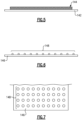
Figure 6 is a side schematic view of an example textured surface of the example condenser. -
Figure 7 is a top schematic view of the example texture surface. -
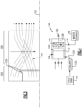
Figure 1 schematically illustrates an aircraft propulsion system in the form of an example hydrogen steam injected inter-cooled turbine engine that is generally indicated at 20. Theengine 20 includes a core engine with a core airflow path C through afan 22, acompressor section 24, acombustor 30 and aturbine section 32. Thefan 22 drives inlet air as acore flow 25 into thecompressor section 24. In thecompressor section 24, thecore flow 25 is compressed and communicated to acombustor 30. In thecombustor 30, thecore flow 25 is mixed with a hydrogen (H2)fuel flow 45 and ignited to generate a highenergy gas flow 55 that expands through theturbine section 32 where energy is extracted and utilized to drive thefan 22 and thecompressor section 24. Abypass flow 18 may flow through thefan 22, bypass the remaining components of theengine 20, and exit through afan nozzle 94. The highenergy gas flow 55 is exhausted from theturbine section 32 and communicated to asteam generation system 70 and awater recovery system 78 before being exhausted through acore nozzle 96. - The
engine 20 is configured to burn hydrogen provide by afuel system 52. Thefuel system 52 includes a liquid hydrogen (LH2)tank 54 in communication with at least onepump 56. Thepump 56 drives afuel flow 45 to thecombustor 30. LH2 provides a thermal heat sink that can be utilized to cool various heat loads within the aircraft indicated at 60 and in the engine as indicated at 62. The heat loads may include, for example and without limitation, super conducting electrics, a working fluid of an environmental control system of the aircraft, an air conditioning heat exchanger, and engine working fluid heat exchangers. Heat accepted into the hydrogen fuel flow increase the overall fuel temperature prior to injection into thecombustor 30. - A
hydrogen expansion turbine 58 may be provided to reduce the pressure of the LH2 fuel flow through expansion prior to communication to thecombustor 30. Expansion in theexpansion turbine 58 provides for the temperatures and pressures of the fuel flow to enter thecombustor 30 as a gas and not a liquid. - The
steam injection system 70 uses the exhaust heat to generate a steam flow by evaporating high pressure water through anevaporator 72. The generated steam may then be injected into compressed core airflow at alocation 76 for communication into thecombustor 30 to improve performance by increasing turbine mass flow and power output without additional work required by the compressor section. In one example embodiment thelocation 76 is upstream of thecombustor 30. Steam flow from theevaporator 72 may drive asteam turbine 74 to provide an additional work output prior to injection into thecombustor 30. - The
water recovery system 78 draws water, schematically indicated at 35, from the highenergy gas flow 55 and communicates the recovered water towater storage tank 82. Thewater storage tank 82 operates as an accumulator to provide sufficient water for operation during various engine operating conditions. A condenser/water separator 80 is provided downstream of theturbine section 32 and theevaporator 72. The condenser/separator 80 is in communication with a cold sink, schematically indicated at 98 for the condenser/separator 80 may be, for example, ram or fan air depending on the application and/or engine configuration. - The
engine 20 has an increased power output from the injected steam due to an increasing mass flow through theturbine section 32 without a corresponding increase in work from thecompressor section 24. An example engine operation cycle may include up to (or more than) 35% steam-air-ratios (SAR) and may be assisted by a multiple fold (e.g., 2x, 3x, etc.) increase in moisture from burning H2 as the fuel. - The
water recovery system 78 includes thewater storage tank 82 that receives water from the condenser/water separator 80 and provides for the accumulation of a volume of water required for production of sufficient amounts of steam. Water recovered from the exhaust gas flow is driven by alow pressure pump 84 and ahigh pressure pump 86 to theevaporator 72. - A
water intercooling flow 88 may be communicated to thecompressor section 24 to reduce a temperature of thecore airflow 25 and increase mass flow. Reduced temperatures and increased mass flow provided by injection of water increases compressor efficiency. Water may also be used as acooling flow 92 to cool coolingair flow 90 communicated from thecompressor section 24 to theturbine section 32. - The
example compressor section 24 includes a low pressure compressor (LPC) 26 and a high pressure compressor (HPC) 28. Theturbine section 32 includes a high pressure turbine (HPT) 34, an intermediate pressure turbine (IPT) 36, and a low pressure turbine (LPT) 38. Theturbines high shaft 64 to drive thehigh pressure compressor 28. Anintermediate shaft 66 couples theintermediate turbine 36 to thelow pressure compressor 26. - A
low shaft 68 is coupled to thelow pressure turbine 38 and agearbox 40 to drive thefan 22. Thelow shaft 68 may further be coupled to anelectric machine 42 that is configured to impart and/or extract power into thelow shaft 68. Theexample gearbox 40 is an epicyclical gear train, such as a planetary gear system, star gear system or other known gear system, with a gear reduction ratio of greater than about 2.3. - Although the
example engine 20 is described and shown by way of example as a three spool engine, other engine configurations, such as two-spool may also benefit from this disclosure and are within the contemplation and scope of this disclosure. - Referring to
Figure 2 , with continued reference toFigure 1 , the example condenser/water separator 80 is schematically shown. Thecondenser 80 includes a plurality ofrotating passages 100 that rotate to induce a centrifugal force on water from thegas flow 55. Acoolant flow 124 from acoolant reservoir 122 is placed in thermal communication with thegas flow 55 to transform a portion of steam into liquid water. The liquid water, schematically indicated at 116 is directed by acollector 112 through anopening 114 to thewater storage 82. Thecoolant flow 124 is directed to anouter periphery 126 of thecondenser 80 and into thermal communication with thegas flow 55. - The
rotating passages 100 are disposed about acondenser axis 110 and supported on ashaft 128. Theshaft 128 is supported by bearingsystems 130 in one disclosed embodiment. Thecondenser 80 includes a firstaxial portion 104 that initially received thegas flow 55. Atransition region 102 is disposed between theaxil portion 104 and therotating passages 100. Thetransition region 102 induces an initial swirl on theincoming gas flow 55. From the transition region, thegas flow 55 enters therotating passages 100. Thegas flow 55 in therotating passages 100 includes anaxial component 120 and atransverse component 118. Thetransverse component 118 provides for the heavier liquid water to be driven radially outward into thecollector 112. Thecollector 112 surrounds the rotating passages and includes at least oneopening 114 for liquid water condensate water flow. It should be appreciated that thecollector 112 may include a plurality ofopenings 114 arranged to capturewater flow 116 at various axial and radial locations. - In the disclosed example, a
motor 132 is coupled to theshaft 128 to rotate therotating passages 100. Themotor 132 is configured to rotate thepassages 100 at a predefined speed determined to generate sufficient centrifugal forces in the direction indicated at 118 to driveliquid water flow 116 outward into thecollector 112. - In this example embodiment, the
collector 112 is a formed sheet material that substantially surrounds the passages through theaxis portion 104, thetransition region 102 and therotating passages 100. The passages through thecondenser 80 maybe formed from sheet metal material, as a cast part or by additive manufacturing processes. Moreover, it should be appreciated that it is within the contemplation and scope of this disclosure that theexample condenser 80 may be formed using other manufacturing and assembly processes. - Referring to
Figure 3 , with continued reference toFigure 2 , therotating passages 100 and the transition region are schematically shown with gas flows 55 and thecoolant flow 124. In one disclosed embodiment, thegas flow 55 and thecoolant flow 124 are maintained separately although in thermal communication. In another disclosed embodiment, thecoolant flow 124 is comprised of a coolant that is allowed to mix with exhausted gas flows 55 that are exhausted from thecondenser 80. - Referring to
Figure 4 , another example condenser embodiment is schematically shown and indicated at 140. Theexample condenser 140 includes the same features as the previously describedcondenser 80 but does not include themotor 132. Instead, thecondenser 140 uses the axial momentum of the high energyexhaust gas flow 55 to drive rotation of the plurality ofrotating passages 100. Therotating passages 100 are spiral shaped such that as theaxial gas flow 55 impacts sides of thepassages 100, an auto rotation is induced that provides the desired centrifugal forces to separate the liquids as a water flow. Thepassages 100 are supported on theshaft 128 andbearings 130 and uses the inherent momentum of thegas flow 55 to drive rotation. - It should be understood that it is within the contemplation of this disclosure that the
rotating passages 100 may be configured to auto rotate in some engine operating conditions according to the example described inFigure 4 and also may include amotor 132 to drive rotation in other operating conditions. Accordingly, themotor 132 may be provided and used only during specific operating conditions where the momentum of thegas flow 55 may not provide the desired magnitude of centrifugal force. - Referring to
Figure 5 , surfaces 142 of thepassages 100 may be provided with acoating 144 that aids in the condensation of water from thegas flow 55. In one disclosed example embodiment, thecoating 144 comprise a hydrophilic material. In another disclosed example embodiment, thecoating 144 comprises a hydrophobic material. Still in another disclosed example embodiment, thecoating 144 may be a pattern of alternating sections made from a hydrophobic material and other sections including hydrophilic material to drive and gather condensate from thegas flow 55. - Referring to
Figures 6 and 7 , surfaces 146 within theexample condensers gas flow 55. In one disclosed example, thesurfaces 146 include atexture 148 formed from a plurality of raised bumps. Thetexture 148 may be configured to induce a turbulent flow near thesurfaces 146 to enhance thermal transfer and thereby accelerate cooling and liquid extraction. - Accordingly, the
example condensers - Although an example engine configuration is described by way of example, it will be appreciated that other engine configurations may include additional structures and features and are within the contemplation and scope of this disclosure.
- Accordingly, the disclosed assemblies provide for the advantageous use of hydrogen fuel to improve engine efficiency and reduce carbon emission. The disclosed systems use the advantageous thermal capacity of hydrogen to maximize the recapture of heat and cool other working flows of the engine.
- Although an example embodiment has been disclosed, a worker of ordinary skill in this art would recognize that certain modifications would come within the scope of this disclosure. For that reason, the following claims should be studied to determine the scope and content of this disclosure.
Claims (8)
- A water recovery system (78) for an aircraft propulsion system, the water recovery system (78) comprising:a condenser (80) arranged along a core flow path (C) of a propulsion system and configured to extract water from a high energy gas flow (55), the condenser (80) including a plurality of rotating passages (100) disposed in a collector (112), wherein the passages (100) are configured to rotate about a condenser axis (110) to generate a transverse pressure gradient to direct water out of the high energy gas flow (55) toward the collector (112);a water storage tank (82) in communication with the collector (112) configured to receive water extracted from the high energy gas flow (55) to the water storage tank (82); andat least one water pump (84; 86) for communicating water from the water storage tank (82) to the propulsion system.
- The water recovery system (78) as recited in claim 1, wherein the condenser (80) is configured to receive a cooling flow (124) to cool the high energy gas flow (55) within the plurality of rotating passages (100).
- The water recovery system (78) as recited in claim 1 or 2, wherein the plurality of rotating passages (100) are defined between a plurality of curved layers extending axially and curving about a condenser axis (110).
- The water recovery system (78) as recited in any of claims 1 to 3, including a shaft (128) supporting the plurality of rotating passages (100) for rotation about the condenser axis (110).
- The water recovery system (78) as recited in claim 4, including a motor (132) coupled to the shaft (128) to drive rotation of the plurality of rotating passages (100).
- The water recovery system (78) as recited in any preceding claim, wherein the plurality of rotating passages (100) include a hydrophilic coating.
- The water recovery system (78) as recited in any preceding claim, wherein the plurality of rotating passages (100) include a hydrophobic coating.
- The water recovery system (78) as recited in any preceding claim, wherein the plurality of rotating passages (100) include a textured surface.
Applications Claiming Priority (2)
| Application Number | Priority Date | Filing Date | Title |
|---|---|---|---|
| US17/744,379 US11920515B2 (en) | 2022-05-13 | 2022-05-13 | Condenser for hydrogen steam injected turbine engine |
| EP23173237.1A EP4276291B1 (en) | 2022-05-13 | 2023-05-12 | Condenser for hydrogen steam injected turbine engine |
Related Parent Applications (1)
| Application Number | Title | Priority Date | Filing Date |
|---|---|---|---|
| EP23173237.1A Division EP4276291B1 (en) | 2022-05-13 | 2023-05-12 | Condenser for hydrogen steam injected turbine engine |
Publications (2)
| Publication Number | Publication Date |
|---|---|
| EP4582675A2 true EP4582675A2 (en) | 2025-07-09 |
| EP4582675A3 EP4582675A3 (en) | 2025-08-06 |
Family
ID=86378338
Family Applications (2)
| Application Number | Title | Priority Date | Filing Date |
|---|---|---|---|
| EP25170201.5A Pending EP4582675A3 (en) | 2022-05-13 | 2023-05-12 | Condenser for hydrogen steam injected tubine engine |
| EP23173237.1A Active EP4276291B1 (en) | 2022-05-13 | 2023-05-12 | Condenser for hydrogen steam injected turbine engine |
Family Applications After (1)
| Application Number | Title | Priority Date | Filing Date |
|---|---|---|---|
| EP23173237.1A Active EP4276291B1 (en) | 2022-05-13 | 2023-05-12 | Condenser for hydrogen steam injected turbine engine |
Country Status (2)
| Country | Link |
|---|---|
| US (1) | US11920515B2 (en) |
| EP (2) | EP4582675A3 (en) |
Families Citing this family (6)
| Publication number | Priority date | Publication date | Assignee | Title |
|---|---|---|---|---|
| US12523176B2 (en) | 2022-06-22 | 2026-01-13 | General Electric Company | Gearbox assembly with lubricant extraction volume ratio |
| EP4390088A1 (en) * | 2022-12-21 | 2024-06-26 | MTU Aero Engines AG | Method for operating a turbomachine for an aircraft engine |
| US12031485B1 (en) * | 2023-04-21 | 2024-07-09 | Rtx Corporation | Water storage precooling and water cycle chiller |
| US12012892B1 (en) * | 2023-05-19 | 2024-06-18 | Rtx Corporation | Water separator for turbine engine |
| US12221905B1 (en) * | 2023-08-07 | 2025-02-11 | General Electric Company | Turbine engine including a steam system |
| US20250369393A1 (en) * | 2024-05-30 | 2025-12-04 | Rtx Corporation | Axial flow angled condenser arrangement for an aircraft propulsion system |
Family Cites Families (8)
| Publication number | Priority date | Publication date | Assignee | Title |
|---|---|---|---|---|
| US3657879A (en) * | 1970-01-26 | 1972-04-25 | Walter J Ewbank | Gas-steam engine |
| US4248039A (en) * | 1978-12-06 | 1981-02-03 | International Power Technology, Inc. | Regenerative parallel compound dual fluid heat engine |
| US10247408B2 (en) * | 2014-11-14 | 2019-04-02 | University Of Florida Research Foundation, Inc. | Humid air turbine power, water extraction, and refrigeration cycle |
| GB201501045D0 (en) | 2015-01-22 | 2015-03-11 | Rolls Royce Plc | Aircraft propulsion system |
| GB2531632B (en) | 2015-08-10 | 2017-01-11 | Latif Qureshi Masood | A mechanical device to suppress contrail formation |
| DE102018203159B4 (en) | 2018-03-02 | 2021-05-06 | MTU Aero Engines AG | Reduction of contrails when operating aircraft |
| DE102018208026A1 (en) * | 2018-05-22 | 2019-11-28 | MTU Aero Engines AG | An exhaust treatment device, aircraft propulsion system, and method of treating an exhaust flow |
| GB202114829D0 (en) * | 2021-10-18 | 2021-12-01 | Rolls Royce Plc | Aircraft propulsion system |
-
2022
- 2022-05-13 US US17/744,379 patent/US11920515B2/en active Active
-
2023
- 2023-05-12 EP EP25170201.5A patent/EP4582675A3/en active Pending
- 2023-05-12 EP EP23173237.1A patent/EP4276291B1/en active Active
Also Published As
| Publication number | Publication date |
|---|---|
| US11920515B2 (en) | 2024-03-05 |
| EP4276291B1 (en) | 2025-04-16 |
| US20230366351A1 (en) | 2023-11-16 |
| EP4582675A3 (en) | 2025-08-06 |
| EP4276291A1 (en) | 2023-11-15 |
Similar Documents
| Publication | Publication Date | Title |
|---|---|---|
| EP4582675A2 (en) | Condenser for hydrogen steam injected tubine engine | |
| EP4276292B1 (en) | Propulsion system for an aircraft | |
| EP4279722B1 (en) | WATER SEPARATOR FOR HYDROGEN-DRIVED TURBINE ENGINE | |
| EP4279720B1 (en) | Superheated steam injection turbine engine | |
| EP4321744B1 (en) | Inter-cooled preheat of steam injected turbine engine | |
| EP4279718B1 (en) | Hydrogen fueled turbine engine condenser duct | |
| EP4407162A1 (en) | Hydrogen steam injected turbine engine with turboexpander heat recovery | |
| EP4279723A1 (en) | Hydrogen steam injected and inter-cooled turbine engine | |
| EP4411122A2 (en) | A propulsion system for an aircraft | |
| EP4414542A1 (en) | Water separator for hydrogen steam injected turbine engine | |
| EP4407160A1 (en) | Power electronics waste heat recovery in recuperation cycle | |
| EP4279719B1 (en) | Hydrogen steam injected turbine engine with cooled cooling air | |
| EP4279721B1 (en) | Reverse flow hydrogen steam injected turbine engine | |
| EP4455465A1 (en) | Offset core with side ejector nacelle nozzles | |
| US20250250932A1 (en) | Turbine Engine Including a Condenser System | |
| EP4517069A1 (en) | Partial exhaust bottoming cycle | |
| EP4656860A1 (en) | Axial flow tapered condenser arrangement for an aircraft propulsion system |
Legal Events
| Date | Code | Title | Description |
|---|---|---|---|
| PUAI | Public reference made under article 153(3) epc to a published international application that has entered the european phase |
Free format text: ORIGINAL CODE: 0009012 |
|
| STAA | Information on the status of an ep patent application or granted ep patent |
Free format text: STATUS: THE APPLICATION HAS BEEN PUBLISHED |
|
| REG | Reference to a national code |
Ref country code: DE Ref legal event code: R079 Free format text: PREVIOUS MAIN CLASS: F01D0025120000 Ipc: F02C0003220000 |
|
| PUAL | Search report despatched |
Free format text: ORIGINAL CODE: 0009013 |
|
| AC | Divisional application: reference to earlier application |
Ref document number: 4276291 Country of ref document: EP Kind code of ref document: P |
|
| AK | Designated contracting states |
Kind code of ref document: A2 Designated state(s): AL AT BE BG CH CY CZ DE DK EE ES FI FR GB GR HR HU IE IS IT LI LT LU LV MC ME MK MT NL NO PL PT RO RS SE SI SK SM TR |
|
| AK | Designated contracting states |
Kind code of ref document: A3 Designated state(s): AL AT BE BG CH CY CZ DE DK EE ES FI FR GB GR HR HU IE IS IT LI LT LU LV MC ME MK MT NL NO PL PT RO RS SE SI SK SM TR |
|
| RIC1 | Information provided on ipc code assigned before grant |
Ipc: F02C 3/22 20060101AFI20250627BHEP Ipc: B01D 53/24 20060101ALI20250627BHEP Ipc: B01D 53/26 20060101ALI20250627BHEP Ipc: F01D 25/30 20060101ALI20250627BHEP Ipc: F01D 25/32 20060101ALI20250627BHEP Ipc: F02C 3/30 20060101ALI20250627BHEP Ipc: F02K 1/82 20060101ALI20250627BHEP |
|
| STAA | Information on the status of an ep patent application or granted ep patent |
Free format text: STATUS: REQUEST FOR EXAMINATION WAS MADE |
|
| 17P | Request for examination filed |
Effective date: 20260206 |