EP4582671A1 - Turbomaschinenstatoranordnung mit tandem-schaufelreihen - Google Patents
Turbomaschinenstatoranordnung mit tandem-schaufelreihen Download PDFInfo
- Publication number
- EP4582671A1 EP4582671A1 EP24305026.7A EP24305026A EP4582671A1 EP 4582671 A1 EP4582671 A1 EP 4582671A1 EP 24305026 A EP24305026 A EP 24305026A EP 4582671 A1 EP4582671 A1 EP 4582671A1
- Authority
- EP
- European Patent Office
- Prior art keywords
- blade
- upstream
- downstream
- stator assembly
- blades
- Prior art date
- Legal status (The legal status is an assumption and is not a legal conclusion. Google has not performed a legal analysis and makes no representation as to the accuracy of the status listed.)
- Pending
Links
Images

Classifications
-
- F—MECHANICAL ENGINEERING; LIGHTING; HEATING; WEAPONS; BLASTING
- F01—MACHINES OR ENGINES IN GENERAL; ENGINE PLANTS IN GENERAL; STEAM ENGINES
- F01D—NON-POSITIVE DISPLACEMENT MACHINES OR ENGINES, e.g. STEAM TURBINES
- F01D5/00—Blades; Blade-carrying members; Heating, heat-insulating, cooling or antivibration means on the blades or the members
- F01D5/12—Blades
- F01D5/14—Form or construction
- F01D5/141—Shape, i.e. outer, aerodynamic form
- F01D5/146—Shape, i.e. outer, aerodynamic form of blades with tandem configuration, split blades or slotted blades
-
- F—MECHANICAL ENGINEERING; LIGHTING; HEATING; WEAPONS; BLASTING
- F01—MACHINES OR ENGINES IN GENERAL; ENGINE PLANTS IN GENERAL; STEAM ENGINES
- F01D—NON-POSITIVE DISPLACEMENT MACHINES OR ENGINES, e.g. STEAM TURBINES
- F01D9/00—Stators
- F01D9/02—Nozzles; Nozzle boxes; Stator blades; Guide conduits, e.g. individual nozzles
- F01D9/04—Nozzles; Nozzle boxes; Stator blades; Guide conduits, e.g. individual nozzles forming ring or sector
- F01D9/041—Nozzles; Nozzle boxes; Stator blades; Guide conduits, e.g. individual nozzles forming ring or sector using blades
-
- F—MECHANICAL ENGINEERING; LIGHTING; HEATING; WEAPONS; BLASTING
- F05—INDEXING SCHEMES RELATING TO ENGINES OR PUMPS IN VARIOUS SUBCLASSES OF CLASSES F01-F04
- F05D—INDEXING SCHEME FOR ASPECTS RELATING TO NON-POSITIVE-DISPLACEMENT MACHINES OR ENGINES, GAS-TURBINES OR JET-PROPULSION PLANTS
- F05D2250/00—Geometry
- F05D2250/30—Arrangement of components
- F05D2250/31—Arrangement of components according to the direction of their main axis or their axis of rotation
- F05D2250/312—Arrangement of components according to the direction of their main axis or their axis of rotation the axes being parallel to each other
-
- F—MECHANICAL ENGINEERING; LIGHTING; HEATING; WEAPONS; BLASTING
- F05—INDEXING SCHEMES RELATING TO ENGINES OR PUMPS IN VARIOUS SUBCLASSES OF CLASSES F01-F04
- F05D—INDEXING SCHEME FOR ASPECTS RELATING TO NON-POSITIVE-DISPLACEMENT MACHINES OR ENGINES, GAS-TURBINES OR JET-PROPULSION PLANTS
- F05D2250/00—Geometry
- F05D2250/30—Arrangement of components
- F05D2250/31—Arrangement of components according to the direction of their main axis or their axis of rotation
- F05D2250/314—Arrangement of components according to the direction of their main axis or their axis of rotation the axes being inclined in relation to each other
Definitions
- the invention thus provides a turbomachine stator assembly comprising successive rows of stator blades in a tandem configuration, a turbomachine compressor comprising such a stator assembly, as well as a turbomachine comprising such a stator assembly or such a compressor.
- turbomachine modules in order to reduce the size and weight of a turbomachine, it is possible to make the turbomachine modules more compact, and in particular the compressors, especially low pressure ones, by reducing the number of compression stages.
- this requires driving the rotor faster in rotation.
- the compressor is then said to be transonic when at least one radially external part of the rotor moves at a speed greater than that of sound.
- a particularly critical point in this regard is the last compression stage of the compressor, which must imperatively restore a substantially axial flow.
- a first grid of blades whose purpose is to accommodate a flow with a strong variation in the angle of incidence, is followed by a second grid of blades which is responsible for completing the remaining deviation with an operation always adapted thanks to the work of filtering the incidence of the first grid.
- the invention aims to at least partially remedy the needs mentioned above and the drawbacks relating to the achievements of the prior art.
- the invention is the result of technological research aimed at significantly improving aircraft performance and, in this sense, contributes to reducing the environmental impact of aircraft.
- the invention aims to propose a turbomachine rectifier or stator configuration making it possible to achieve the necessary flow deflection at all operating points of the turbomachine, and for a wide range of angles of incidence, to axially straighten the upstream flow so as to correctly supply a downstream zone. It thus aims to propose a rectifier or stator design making it possible to improve the compactness of the turbomachine without harming the efficiency, and this over the entire operating range, including transonic, of the turbomachine.
- the invention it is possible to design a rectifier or stator principle in tandem configuration capable of tolerating a large range of flow incidence and of achieving a large flow deflection, by means of optimizing the design parameters of the rows of blades constituting the stator assembly.
- the optimization proposed by the invention makes it possible to obtain better performances in terms of aerodynamic losses, residual gyration at the outlet and surge margin.
- the capacities of the tandem configuration in terms of resistance to incidence and aerodynamic load (high deviation) are improved.
- the stator assembly according to the invention may further comprise one or more of the following characteristics taken in isolation or in any possible technical combinations.
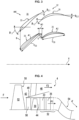
- the turbomachine may comprise a moving wheel and a separation nozzle, arranged downstream of the moving wheel and separating an annular air flow into a primary flow traveling through an internal vein and a secondary flow traveling through an external vein, the stator assembly being arranged in the internal vein upstream of a swan neck shape.
- the chord of the upstream 33 and downstream 35 blades which connects the leading edge to the trailing edge, is respectively denoted C 33 and C 35 .
- the chord C 33 of the upstream 33 blades may be different from the chord C 35 of the downstream 35 blades.
- the length A0 formed axially between the two rows of upstream 33 and downstream 35 blades is also shown on the figures 2 And 3 .
- This length A0 can be similar to an axial overlap length when the position of the blades 33, 35 is such that they overlap at least partially, thus providing axial overlap over at least part of their radial height. In the example shown in figures 2 And 3 , the rows of blades 33, 35 do not overlap.
- the spacing between the trailing edge of an upstream blade 33 and the leading edge of an adjacent downstream blade 35 is quantified by a circumferential spacing length between blades of the tandem, denoted t on the Figure 3 , measured perpendicular to the X axis in a similar way to the measurement of the pitch S between two adjacent blades in the same row.
- Design parameters are advantageously provided for the stator assembly 32 according to the invention. These parameters are determined in particular between 10% and 90% of the radial height H33 of an upstream blade 33 and between 10% and 90% of the radial height H35 of a downstream blade 35.
- the azimuthal offset Da is chosen such that 0 ⁇ Da ⁇ 0.50, in particular 0.15 ⁇ Da ⁇ 0.35.
- the incidence protection Pi is chosen such that 0 ⁇ Pi ⁇ 12°, in particular 3° ⁇ Pi ⁇ 9°.
- the deviation distribution Rd is chosen such that 1.1 ⁇ Rd ⁇ 3.9, notably 1.7 ⁇ Rd ⁇ 3.3.
- the chord ratio Rc is chosen such that 0.5 ⁇ Rc ⁇ 1.5, notably 0.7 ⁇ Rc ⁇ 1.2.
- FIG. 4 illustrates an example of possible installation of the stator assembly 32 according to the invention in a turbomachine 1 such as that shown in the Figure 1 , preferably downstream of a flow separator.
- a rotating or rotor assembly in the form of a mobile wheel 50, in particular a fan, the blades 52 of which extend radially upstream of the primary 44 and secondary 46 annular veins.
- the stator assembly 32 consisting of an annular row of stator blades 33 and a row of stator blades 35 forming the tandem, is preferably arranged in the primary annular vein 44, in the low-pressure compressor 4 also comprising rotor blades 30, and precedes a swan-neck shape 54 which is arranged upstream of the high pressure compressor 4'.
- the stator assembly 32 constitutes the last blades 33, 35 of the low pressure compressor 4 and makes it possible to axially straighten the primary flow F1 coming from the upstream stages in order to correctly supply the swan neck 54 located downstream.
- the low pressure compressor 4 may comprise variable stator vanes, or VSV for "Variable Stator Vanes" in English, and the stator assembly 32 may comprise the only stator vanes of the low pressure compressor 4 which are not variable.
- the low pressure compressor 4 may comprise between 1 and 4 compression stages, each formed of at least one row or annular grid of rotor vanes directly followed by at least one row or grid of stator vanes.
Landscapes
- Engineering & Computer Science (AREA)
- Mechanical Engineering (AREA)
- General Engineering & Computer Science (AREA)
- Physics & Mathematics (AREA)
- Fluid Mechanics (AREA)
- Structures Of Non-Positive Displacement Pumps (AREA)
Priority Applications (4)
| Application Number | Priority Date | Filing Date | Title |
|---|---|---|---|
| EP24305026.7A EP4582671A1 (de) | 2024-01-08 | 2024-01-08 | Turbomaschinenstatoranordnung mit tandem-schaufelreihen |
| PCT/FR2025/050017 WO2025149725A1 (fr) | 2024-01-08 | 2025-01-07 | Ensemble statorique de turbomachine comportant des rangées d'aubes en tandem |
| FR2500101A FR3158118A1 (fr) | 2024-01-08 | 2025-01-07 | Ensemble statorique de turbomachine comportant des rangées d’aubes en tandem |
| BE20250004A BE1032248A1 (fr) | 2024-01-08 | 2025-01-07 | Ensemble statorique de turbomachine comportant des rangées d'aubes en tandem |
Applications Claiming Priority (1)
| Application Number | Priority Date | Filing Date | Title |
|---|---|---|---|
| EP24305026.7A EP4582671A1 (de) | 2024-01-08 | 2024-01-08 | Turbomaschinenstatoranordnung mit tandem-schaufelreihen |
Publications (1)
| Publication Number | Publication Date |
|---|---|
| EP4582671A1 true EP4582671A1 (de) | 2025-07-09 |
Family
ID=90721266
Family Applications (1)
| Application Number | Title | Priority Date | Filing Date |
|---|---|---|---|
| EP24305026.7A Pending EP4582671A1 (de) | 2024-01-08 | 2024-01-08 | Turbomaschinenstatoranordnung mit tandem-schaufelreihen |
Country Status (1)
| Country | Link |
|---|---|
| EP (1) | EP4582671A1 (de) |
Citations (9)
| Publication number | Priority date | Publication date | Assignee | Title |
|---|---|---|---|---|
| EP2409002A2 (de) | 2009-03-16 | 2012-01-25 | MTU Aero Engines GmbH | Tandemschaufelkonstruktion |
| DE102014203607A1 (de) * | 2014-02-27 | 2015-08-27 | Rolls-Royce Deutschland Ltd & Co Kg | Schaufelreihengruppe |
| DE102014203604A1 (de) * | 2014-02-27 | 2015-08-27 | Rolls-Royce Deutschland Ltd & Co Kg | Schaufelreihengruppe |
| EP2913480A1 (de) | 2014-02-27 | 2015-09-02 | Rolls-Royce Deutschland Ltd & Co KG | Tandemschaufel einer Strömungsmaschine |
| DE102014206217A1 (de) * | 2014-04-01 | 2015-10-01 | Deutsches Zentrum für Luft- und Raumfahrt e.V. | Verdichtungsgitter für einen Axialverdichter |
| DE102018108940A1 (de) | 2018-04-16 | 2019-10-17 | Rolls-Royce Deutschland Ltd & Co Kg | Turbofantriebwerk für ein Luftfahrzeug |
| CA3057210A1 (en) * | 2018-10-05 | 2020-04-05 | Pratt & Whitney Canada Corp. | Double row compressor stators |
| US20200240283A1 (en) | 2019-01-24 | 2020-07-30 | MTU Aero Engines AG | Guide vane cascade for a turbomachine |
| WO2023193997A1 (fr) * | 2022-04-05 | 2023-10-12 | Safran Aero Boosters | Stator tandem |
-
2024
- 2024-01-08 EP EP24305026.7A patent/EP4582671A1/de active Pending
Patent Citations (10)
| Publication number | Priority date | Publication date | Assignee | Title |
|---|---|---|---|---|
| EP2409002A2 (de) | 2009-03-16 | 2012-01-25 | MTU Aero Engines GmbH | Tandemschaufelkonstruktion |
| DE102014203607A1 (de) * | 2014-02-27 | 2015-08-27 | Rolls-Royce Deutschland Ltd & Co Kg | Schaufelreihengruppe |
| DE102014203604A1 (de) * | 2014-02-27 | 2015-08-27 | Rolls-Royce Deutschland Ltd & Co Kg | Schaufelreihengruppe |
| EP2913480A1 (de) | 2014-02-27 | 2015-09-02 | Rolls-Royce Deutschland Ltd & Co KG | Tandemschaufel einer Strömungsmaschine |
| DE102014206217A1 (de) * | 2014-04-01 | 2015-10-01 | Deutsches Zentrum für Luft- und Raumfahrt e.V. | Verdichtungsgitter für einen Axialverdichter |
| DE102018108940A1 (de) | 2018-04-16 | 2019-10-17 | Rolls-Royce Deutschland Ltd & Co Kg | Turbofantriebwerk für ein Luftfahrzeug |
| CA3057210A1 (en) * | 2018-10-05 | 2020-04-05 | Pratt & Whitney Canada Corp. | Double row compressor stators |
| US20200240283A1 (en) | 2019-01-24 | 2020-07-30 | MTU Aero Engines AG | Guide vane cascade for a turbomachine |
| WO2023193997A1 (fr) * | 2022-04-05 | 2023-10-12 | Safran Aero Boosters | Stator tandem |
| BE1030421A1 (fr) | 2022-04-05 | 2023-10-27 | Safran Aero Boosters | Stator tandem |
Similar Documents
| Publication | Publication Date | Title |
|---|---|---|
| EP3676480B1 (de) | Turbomaschinengebläse-strömungsgleichrichterschaufel, turbomaschinenanordnung mit solch einer schaufel und mit besagter schaufel oder besagter anordnung ausgestattete turbomaschine | |
| FR3027053B1 (fr) | Stator de turbomachine d'aeronef | |
| EP3927945B1 (de) | Statorring einer turbomaschine welche statorschaufeln mit unterschidlicher sehnenlänge aufweist | |
| EP4073369A1 (de) | Flugzeugantriebssystem mit verbesserter antriebseffizienz | |
| EP4111062B1 (de) | Transonischer turbomaschinenverdichter | |
| EP4582671A1 (de) | Turbomaschinenstatoranordnung mit tandem-schaufelreihen | |
| EP4582672A1 (de) | Turbomaschinenstatoranordnung mit tandem-schaufelreihen | |
| EP4582670A1 (de) | Turbomaschinenstatoranordnung mit tandem-schaufelreihen | |
| FR3158117A1 (fr) | Ensemble statorique de turbomachine comportant des rangées d’aubes en tandem | |
| FR3158118A1 (fr) | Ensemble statorique de turbomachine comportant des rangées d’aubes en tandem | |
| WO2024200946A1 (fr) | Turbomachine comprenant des rangees d'aubes statoriques et un diffuseur dans un canal où circule un troisieme flux | |
| FR3104644A1 (fr) | Système propulsif aéronautique à rendement propulsif amélioré | |
| BE1032189B1 (fr) | Aube pour compresseur de turbomachine d'aeronef, compresseur, turbomachine | |
| BE1032191B1 (fr) | Ensemble de turbomachine et turbomachine | |
| BE1028097B1 (fr) | Aube de compresseur de turbomachine, compresseur et turbomachine munis de celle-ci | |
| WO2024224017A1 (fr) | Aube à calage variable de propulseur aéronautique non-caréné | |
| FR3151628A1 (fr) | Soufflante pour propulsion aéronautique | |
| WO2025104401A1 (fr) | Soufflante pour propulsion aéronautique | |
| FR3162059A1 (fr) | Distribution hétérogène de fentes de bord d’attaque | |
| WO2025261703A1 (fr) | Aube pour compresseur de turbomachine d'aeronef, compresseur, turbomachine | |
| FR3160212A1 (fr) | Moteur à turbine à gaz avec cadencement relatif de bifurcations | |
| FR3146494A1 (fr) | Systeme propulsif aeronautique a soufflante carenee et a fort taux de dilution | |
| WO2025093843A1 (fr) | Aube de redresseur avec une fente | |
| WO2024170844A1 (fr) | Optimisation du comportement de la soufflante dans un système propulsif aéronautique | |
| WO2024121465A1 (fr) | Turbomachine d'aéronef a triple flux |
Legal Events
| Date | Code | Title | Description |
|---|---|---|---|
| PUAI | Public reference made under article 153(3) epc to a published international application that has entered the european phase |
Free format text: ORIGINAL CODE: 0009012 |
|
| STAA | Information on the status of an ep patent application or granted ep patent |
Free format text: STATUS: THE APPLICATION HAS BEEN PUBLISHED |
|
| AK | Designated contracting states |
Kind code of ref document: A1 Designated state(s): AL AT BE BG CH CY CZ DE DK EE ES FI FR GB GR HR HU IE IS IT LI LT LU LV MC ME MK MT NL NO PL PT RO RS SE SI SK SM TR |