EP4582657A1 - Flip-in vehicle door handle, vehicle door, and vehicle - Google Patents
Flip-in vehicle door handle, vehicle door, and vehicle Download PDFInfo
- Publication number
- EP4582657A1 EP4582657A1 EP23859499.8A EP23859499A EP4582657A1 EP 4582657 A1 EP4582657 A1 EP 4582657A1 EP 23859499 A EP23859499 A EP 23859499A EP 4582657 A1 EP4582657 A1 EP 4582657A1
- Authority
- EP
- European Patent Office
- Prior art keywords
- grip
- vehicle door
- flip
- link
- handle base
- Prior art date
- Legal status (The legal status is an assumption and is not a legal conclusion. Google has not performed a legal analysis and makes no representation as to the accuracy of the status listed.)
- Pending
Links
Images



Classifications
-
- E—FIXED CONSTRUCTIONS
- E05—LOCKS; KEYS; WINDOW OR DOOR FITTINGS; SAFES
- E05B—LOCKS; ACCESSORIES THEREFOR; HANDCUFFS
- E05B85/00—Details of vehicle locks not provided for in groups E05B77/00 - E05B83/00
- E05B85/10—Handles
- E05B85/107—Pop-out handles, e.g. sliding outwardly before rotation
-
- E—FIXED CONSTRUCTIONS
- E05—LOCKS; KEYS; WINDOW OR DOOR FITTINGS; SAFES
- E05B—LOCKS; ACCESSORIES THEREFOR; HANDCUFFS
- E05B85/00—Details of vehicle locks not provided for in groups E05B77/00 - E05B83/00
- E05B85/10—Handles
- E05B85/103—Handles creating a completely closed wing surface
-
- E—FIXED CONSTRUCTIONS
- E05—LOCKS; KEYS; WINDOW OR DOOR FITTINGS; SAFES
- E05B—LOCKS; ACCESSORIES THEREFOR; HANDCUFFS
- E05B79/00—Mounting or connecting vehicle locks or parts thereof
- E05B79/02—Mounting of vehicle locks or parts thereof
- E05B79/06—Mounting of handles, e.g. to the wing or to the lock
-
- E—FIXED CONSTRUCTIONS
- E05—LOCKS; KEYS; WINDOW OR DOOR FITTINGS; SAFES
- E05B—LOCKS; ACCESSORIES THEREFOR; HANDCUFFS
- E05B81/00—Power-actuated vehicle locks
- E05B81/24—Power-actuated vehicle locks characterised by constructional features of the actuator or the power transmission
- E05B81/26—Output elements
- E05B81/28—Linearly reciprocating elements
-
- E—FIXED CONSTRUCTIONS
- E05—LOCKS; KEYS; WINDOW OR DOOR FITTINGS; SAFES
- E05B—LOCKS; ACCESSORIES THEREFOR; HANDCUFFS
- E05B81/00—Power-actuated vehicle locks
- E05B81/54—Electrical circuits
- E05B81/64—Monitoring or sensing, e.g. by using switches or sensors
- E05B81/76—Detection of handle operation; Detection of a user approaching a handle; Electrical switching actions performed by door handles
-
- E—FIXED CONSTRUCTIONS
- E05—LOCKS; KEYS; WINDOW OR DOOR FITTINGS; SAFES
- E05B—LOCKS; ACCESSORIES THEREFOR; HANDCUFFS
- E05B81/00—Power-actuated vehicle locks
- E05B81/54—Electrical circuits
- E05B81/64—Monitoring or sensing, e.g. by using switches or sensors
- E05B81/76—Detection of handle operation; Detection of a user approaching a handle; Electrical switching actions performed by door handles
- E05B81/77—Detection of handle operation; Detection of a user approaching a handle; Electrical switching actions performed by door handles comprising sensors detecting the presence of the hand of a user
-
- E—FIXED CONSTRUCTIONS
- E05—LOCKS; KEYS; WINDOW OR DOOR FITTINGS; SAFES
- E05B—LOCKS; ACCESSORIES THEREFOR; HANDCUFFS
- E05B85/00—Details of vehicle locks not provided for in groups E05B77/00 - E05B83/00
- E05B85/10—Handles
-
- E—FIXED CONSTRUCTIONS
- E05—LOCKS; KEYS; WINDOW OR DOOR FITTINGS; SAFES
- E05B—LOCKS; ACCESSORIES THEREFOR; HANDCUFFS
- E05B85/00—Details of vehicle locks not provided for in groups E05B77/00 - E05B83/00
- E05B85/10—Handles
- E05B85/14—Handles pivoted about an axis parallel to the wing
- E05B85/18—Handles pivoted about an axis parallel to the wing a longitudinal grip part being pivoted about an axis parallel to the longitudinal axis of the grip part
Definitions
- the present invention relates to the technical field of vehicle components, and in particular to a flip-in vehicle handle, a vehicle door and a vehicle.
- the grip operating portions all protrudes from an outer door panel ( FIG. 1 ).
- the grip operating portion protrudes from the outer door panel, the occupant pulls the grip operating portion to open the vehicle door.
- This type of hidden-type handle has the grip operating portion protruding from the outer door panel, the grip portion is prone to collision and damage, and the maintenance cost is high.
- an overall Y-direction size of a flip-out handle assembly is large (approximately 65mm), which requires large space for arrangement and is difficult to arrange. Therefore, there is a need to develop a flip-in handle to solve the above problems.
- the present invention provides a flip-in vehicle handle, a vehicle door and a vehicle to solve the problem of collision and damage to a grip portion caused by a grip operating portion protruding from the vehicle door outer panel.
- the present invention provides a flip-in vehicle handle, including a handle base, a grip, a linear driving apparatus and a linkage mechanism;
- the handle base is provided with a grip installing groove, the grip is installed in the grip installing groove and is rotatably connected to the handle base;
- the linear driving apparatus is provided on the handle base, the linkage mechanism is rotatably installed on the handle base, a driving input end of the linkage mechanism is hinged to the linear driving apparatus, and an action output end of the linkage mechanism is in sliding connection with the grip; where, when the linear driving apparatus is started, the linkage mechanism is driven to drive the grip blocked on the grip installing groove to rotate toward an inner side of the handle base, so as to expose the grip installing groove.
- the linear driving apparatus includes an electric actuator and a pushing rod, the pushing rod is connected to an output end of the electric actuator, and the pushing rod is driven by the electric actuator to perform linear reciprocating movement.
- the linkage structure includes a first link and a second link, the first link is fixedly connected to the second link to form a V-shaped pivot arm, an intersection of the first link and the second link is rotatably installed on the handle base, an end of the first link facing away from the intersection is in sliding connection with the grip, and an end of the second link facing away from the intersection is hinged to the pushing rod.
- a first torsion spring is provided at a connection between the linkage mechanism and the handle base, and the first torsion spring is sleeved on the second shaft sleeve, two ends of the first torsion spring are respectively fixed to the first shaft sleeve and the handle base.
- a clamping groove is provided at a position where the first link is connected to the grip, a first connecting seat cooperated with the clamping groove is provided on the grip, the grip is in sliding connection with the first link by a cooperation of the first connecting seat and the clamping groove.
- a second torsion spring is provided on the second rotating shaft, and the second torsion spring is sleeved on the second rotating shaft, and two torsion output ends of the second torsion spring are respectively connected to the second connecting seat.
- the flip-in vehicle door handle further includes an unlatching switch, the unlatching switch is provided above the grip installing groove and is electrically connected to a control module.
- the flip-in vehicle door handle further includes a grip back cover, and the grip back cover is installed on the handle base.
- the present invention also provides a vehicle, which includes the vehicle door of the present invention or the flip-in vehicle door handle of the present invention.
- the flip-in vehicle door handle of the present invention uses a linkage mechanism to convert the linear movement of the linear driving apparatus into a rotary movement, and then drives the grip to turn inside the vehicle door to realize a flip-in contraction of the grip, which solves the problem that the grip is prone to collision and damage when popping out of the vehicle and compresses the overall Y-direction layout space of the handle at the same time, optimizing the structure of the vehicle door handle and reducing costs.
- the linkage mechanism in the present invention adopts a V-shaped pivot arm structure, which can not only achieve rotational connection with the handle base, but also be hinged with the grip and the linear driving apparatus.
- the linear movement of the pushing rod of the linear driving apparatus drives the rotating arm to rotate around the rotating shaft. Since the rotating arm is connected to the grip, the rotation of the rotating arm drives the grip to rotate to the inside of the grip installing groove, thereby realizing the force transmission of the linear driving apparatus;
- the linkage mechanism and the connection between the grip and the handle base are provided with torsion springs, which can make the linkage mechanism and grip always maintain resilience and have a tendency to return to their initial position.
- the present invention provides a flip-in vehicle door handle, a vehicle door and a vehicle to solve the problem that the grip is prone to collision and damage when popping out from the vehicle.
- the flip-in vehicle door handle of the present invention includes a handle base 100, a grip 200, a linkage mechanism 300 and a linear driving apparatus 400.
- the handle base 100 is provided with a grip installing groove 110, and the grip 200 is installed in the grip installing groove 110 and is rotatably connected with the handle base 100;
- the linear driving apparatus 400 is disposed on the handle base 100 for driving the grip 200 to rotate;
- the linkage mechanism 300 is rotatably installed on the handle base 100, and a driving input end of the linkage mechanism 300 is hinged to a linear moving driving end of the linear driving apparatus 400, and an action output end of the linkage mechanism 300 is in sliding connection with the grip 200.
- the grip 200 When the vehicle door is in a closed state, the grip 200 covers the grip installing groove 110 and is flush with an outer door panel; when the linear driving apparatus 400 is started, the linear driving apparatus 400 drives the grip 200 covering the grip installing groove 110 through the linkage mechanism 300 to rotate towards an inner side of the handle base 100, so as to expose the grip installing groove.
- the linear driving apparatus 400 includes an electric actuator 410 and a pushing rod 420.
- the pushing rod 420 is installed at an output end of the electric actuator 410.
- the electric actuator 410 outputs a linear driving force
- the pushing rod 420 makes linear reciprocating movement driven by the electric actuator 410.
- the handle base 100 is composed of a bottom plate and side plates located around the bottom plate to form a box-shaped cavity. One side of the box-shaped cavity is provided with a first accommodating cavity 120 for installing the electric actuator and a slide channel 130 for the pushing rod 420 to slide.
- the other side of the box-shaped cavity is provided with a second accommodating cavity 140, and the second accommodating cavity 140 is used to install the linkage mechanism 300 and the grip 200.
- the electric actuator 410 is installed in the first accommodating cavity 120 through a fastener.
- the slide channel 130 is provided at the output end of the electric actuator 410.
- the slide channel 130 is provided transversely along the handle base 100.
- the pushing rod 420 makes linear reciprocating movement in the slide channel 130, under the action of the electric actuator 410.
- the linkage mechanism 300 is installed at a positon of the second accommodating cavity 140 corresponding to the slide channel 130. The linear movement of the pushing rod 420 can drive the linkage mechanism 300 to rotate, thereby driving the grip 200 to flip toward the inner side of the handle base 100.
- Conventional actuator assemblies in the art can be used as the electric actuator 410 in the present embodiment, the specific structure of which will not be repeated herein.
- existing linear driving apparatuses with other structures may be used, for example a driving motor and a turbine worm transmission assembly that cooperates with the driving motor.
- the turbine worm transmission assembly can convert a rotary movement of the driving motor into a linear movement.
- the linkage mechanism 300 includes a first link 310 and a second link 320.
- the first link 310 is fixedly connected to the second link 320 to form a V-shaped pivot arm.
- the intersection of the first link 310 and the second link 320 is rotatably installed to the handle base 100.
- the first link 310 and the second link 320 may also be an integrated structure.
- An end of the first link 310 away from the intersection of the first link 310 and the second link 320 is the action output end of the linkage mechanism 300.
- the action output end is in sliding connection with the grip 200.
- a protrusion 311 is provided on one side of the first link 310 facing the grip 200, and a clamping groove 312 is provided inside the protrusion 311.
- a corresponding position of the grip 200 is provided with a first connecting seat 210 that cooperates with the clamping groove 312.
- the protrusion 311 can be two oppositely arranged bumps, and a gap between the two bumps forms the clamping groove 312; the protrusion 311 can also be an integrated structure, with a clamping groove 312 in the middle thereof.
- the formation mode of the clamping groove 312 is not limited.
- the first connecting seat 210 protrudes from an inner surface of the grip 200.
- the first connecting seat 210 includes two spaced seat bodies 211 and a cross beam 212 connecting the two seat bodies.
- the seat body 211 is in a triangular prism structure, where the cross beam 212 is provided on the seat body 211, and the two ends of the cross beam 212 are connected to the two seat bodies 211 respectively.
- the first connection seat 210 and the grip 200 can be an integrated structure or a separated connection structure.
- the cross beam 212 is always clamped in the clamping groove 212, and a longitudinal size of the cross beam 212 is smaller than an opening size of the clamping groove 312, so that the cross beam 212 and the groove 212 form a sliding pair.
- the linkage mechanism 310 rotates, the first link 310 slides along the cross beam 212 and at the same time drives the grip 200 to flip inward.
- the arrow in FIG. 10 indicates a rotation direction of the grip from a closed state to an open state.
- the end of the second link 320 away from the intersection of the first link 310 and the second link 320 is a power input end of the linkage mechanism 300, and the power input end is hinged to the pushing rod 420.
- one end of the pushing rod 420 is fixedly connected to the output end of the electric actuator 410, and the other end is provided with a clamping groove.
- the second link 320 is inserted into the clamping groove and is hinged with the pushing rod 420 through a pin.
- the electric actuator 410 drives the pushing rod 420 to make linear movement forward (in a direction away from the electric actuator 410).
- the pushing rod 420 drives the linkage mechanism 300 to rotate counterclockwise.
- the first link 310 slides along the cross beam 212 of the first connecting seat 210, and at the same time presses the grip 200 downward to flip the grip 200 toward the inner side of the handle base 100, so that the grip 200 changes from the closed position to the open position.
- the electric actuator 410 drives the pushing rod 420 to make a linear movement backward (in a direction towards the electric actuator 410)
- the pushing rod 420 drives the linkage mechanism 300 to rotate clockwise.
- the linkage structure 300 adopts a V-shaped pivot arm structure, which can not only ensure the normal rotation movement of the linkage mechanism, but also transmit the linear movement of the pushing rod 420 to the grip 200 so that it can flip towards the inner side of the handle base and reset to be flush with the outer door panel.
- the linkage mechanism 300 is rotatably connected to the handle base 100 through a first rotating shaft 350.
- the intersection of the first link 310 and the second link 320 is provided with a first shaft sleeve 330 and a second shaft sleeve 340 protruding towards the handle base 100.
- the first shaft sleeve 330 is provided on a periphery of the second shaft sleeve 340, and forms an annular shaft sleeve with the second shaft sleeve 340.
- the handle base 100 is correspondingly provided with a third shaft sleeve 150 protruding from the handle base 100.
- An outer diameter of the third shaft sleeve 150 matches an inner diameter of the second shaft sleeve 340 and an inner diameter of the third shaft sleeve 150 matches an outer diameter of the first rotating shaft 350, the third shaft sleeve 150 is inserted into the second shaft sleeve 340 to achieve rotational connection through the first shaft sleeve 350.
- a torsion spring is also provided at a connection between the linkage mechanism 300 and the handle base 100, where the torsion spring is referred to a first torsion spring 360.
- the first torsion spring 360 is installed between the first shaft sleeve 330 and the second shaft sleeve 340, two ends of the first torsion spring 360 are connected to the handle base 100 and the linkage mechanism 300 respectively.
- a first installing groove 331 is provided on a side wall of the first shaft sleeve 330
- a shaft sleeve fixing seat 151 is provided on a periphery of the third shaft sleeve 150
- a second installing groove 152 is provided on a side wall of the shaft sleeve fixing seat 151
- the first torsion spring 360 is accommodated in space between the first shaft sleeve 330 and the second shaft sleeve 340, and is sleeved on the second shaft sleeve 340.
- Two ends of the first torsion spring 360 are respectively accommodated in the first installing groove 321 and the second installing groove 152.
- the arrangement of the first torsion spring 360 allows the linkage mechanism to always maintain resilience
- the grip installing groove 110 is provided on a bottom plate of the handle base 100, and located above the linkage mechanism 300.
- the inside cavity of the grip installing groove 110 provides avoiding space for flipping of the grip 200.
- the grip 200 is installed in the grip installing groove 110 and is rotatably connected to the handle base 100 through a second rotating shaft 170.
- a position of the handle base 100 corresponding to that below the grip installing groove 110 is provided with a grip installing seat 160.
- the grip installing seat 160 includes an end portion and a middle portion, and both the end portion and the middle portion are provided with through holes for the rotating shaft to pass through.
- a second connecting seat 220 is provided on one side of the grip 200.
- the second connecting seat 220 is an arched structure, one end of the arched structure is fixed on the grip 200, and the other end is provided with a through hole for the rotating shaft to pass through.
- the second rotating shaft 170 passes through the through holes on the grip installing seat 160 and the second connecting seat 220 to connect them together.
- a sealing structure 230 is provided between the grip 200 and the grip installing groove 110.
- the sealing structure 230 can be a sealing ring arranged along circumference of the grip installing groove 110. When the grip 200 is in a closed state, the sealing ring can seal a gap between the handle base 100 and grip 200.
- a torsion spring is provided at the connection between the grip 200 and the handle base 100.
- the torsion spring is referred to as a second torsion spring 180.
- the second torsion spring 180 includes two torque output portions 181 and a connecting portion 182 connecting the two torque output portions 181.
- the two torque output portions 181 are respectively sleeved on the second connecting seats 220 at both ends of the grip 200, and an output end of the torque output portion 181 is fixed on the second connecting seat 220, the connecting portion 182 bypasses a bottom of the middle portion of the grip installing seat 160.
- the arrangement of the second torsion spring 180 allows the grip 200 to always maintain resilience and have a tendency to return to the initial position.
- two torsion springs may also be used, the two torsion springs are respectively sleeved on the second rotating shaft, and the two ends of the torsion spring are respectively fixed on the second connecting seat 220 and the grip installing seat 160.
- an unlatching switch 190 is provided in the handle base 100, and a grip opening button 240 is provided on an outside of the grip 200.
- the unlatching switch 190 and the grip opening button 240 are respectively in signal communication with a control module for example DCM (Data Communication Module, Data Communication Module) or BCM (Body Control Module, Body Control Module), to realize the touch unlocking function for vehicle door handle.
- the unlatching switch 190 may be an unlatching capacitor or a push-type switch.
- the unlatching switch 190 is set at a position that can be touched by the hand after the grip 200 is opened.
- the unlatching switch 190 is set at a position above a corresponding grip installing groove 110 so that the unlatching switch 190 can be touched in time after the grip 200 is opened.
- the unlatching process of the vehicle door is as follows: when a user approaches the vehicle and touches the grip opening button 240 on the grip 200 by a hand, the control module DCM or BCM controls the electric actuator 410 to start after receiving a signal, so that the pushing rod 420 pushes the linkage mechanism 300 to rotate, the linkage mechanism 300 drives the grip 200 to flip toward an inner side of the vehicle door, exposing the grip installing groove 110. The user's hand reaches into the grip installing groove 110 to touch the unlatching switch 190 in the handle base 100.
- the unlatching switch 190 sends a door lock release signal to the control module.
- the control module sends an unlatching command to the door lock, realizing the unlatching of vehicle door lock.
- a hidden-type vehicle door handle of the present invention also includes a grip back cover 500.
- the grip back cover 500 is covered on the second accommodating cavity 140 and is connected to the handle base 100.
- a positioning protrusion 141 is provided on a side wall of the second accommodating cavity 140.
- a buckle 510 that cooperates with the positioning protrusion 141 is provided at a corresponding position of the grip back cover 500, and the connection between the grip back cover 500 and the handle base 100 is achieved by cooperating the positioning protrusion 141 with the buckle 510.
- the grip back cover 500 is used to seal the grip 200 and the linkage mechanism 300 in the second accommodating cavity 140.
- the present invention also provides a vehicle door, which includes an outer door panel 600 and a vehicle door handle installed on the outer door panel 600, where the vehicle door handle is a flip-in vehicle door handle as described above in the present invention.
- a handle installation hole is provided on the outer door panel 600, a handle base of the flip-in vehicle door handle is fixed inside the outer door panel 600, and the grip can block the handle installation hole.
- the handle In the initial position, the handle is in a closed state, and the grip 200 covers the grip installing groove 110 and is flush with the outer door panel 600; when the handle is opened, the grip 200 flips toward the inside of the vehicle door to prevent the grip 200 from popping out from the vehicle door and causing collision damage.
- the present invention also provides a vehicle, which includes a vehicle body (not shown in the figure), a vehicle door installed on both sides of the vehicle body, and a vehicle door handle installed on the vehicle door, where the vehicle door is the vehicle door described above in the present invention, and the vehicle door handle is the flip-in vehicle door handle mentioned above in the present invention.
- vehicle body not shown in the figure
- vehicle door handle installed on the vehicle door
- the vehicle door is the vehicle door described above in the present invention
- the vehicle door handle is the flip-in vehicle door handle mentioned above in the present invention.
Landscapes
- Lock And Its Accessories (AREA)
Abstract
Description
- The present invention relates to the technical field of vehicle components, and in particular to a flip-in vehicle handle, a vehicle door and a vehicle.
- At present, when the hidden-type flip-out handles on the market are opened, the grip operating portions all protrudes from an outer door panel (
FIG. 1 ). When the grip operating portion protrudes from the outer door panel, the occupant pulls the grip operating portion to open the vehicle door. This type of hidden-type handle has the grip operating portion protruding from the outer door panel, the grip portion is prone to collision and damage, and the maintenance cost is high. Moreover, an overall Y-direction size of a flip-out handle assembly is large (approximately 65mm), which requires large space for arrangement and is difficult to arrange. Therefore, there is a need to develop a flip-in handle to solve the above problems. - In view of the above shortcomings of the prior art, the present invention provides a flip-in vehicle handle, a vehicle door and a vehicle to solve the problem of collision and damage to a grip portion caused by a grip operating portion protruding from the vehicle door outer panel.
- In order to achieve the above objects and other related objects, the present invention provides a flip-in vehicle handle, including a handle base, a grip, a linear driving apparatus and a linkage mechanism; the handle base is provided with a grip installing groove, the grip is installed in the grip installing groove and is rotatably connected to the handle base; the linear driving apparatus is provided on the handle base, the linkage mechanism is rotatably installed on the handle base, a driving input end of the linkage mechanism is hinged to the linear driving apparatus, and an action output end of the linkage mechanism is in sliding connection with the grip; where, when the linear driving apparatus is started, the linkage mechanism is driven to drive the grip blocked on the grip installing groove to rotate toward an inner side of the handle base, so as to expose the grip installing groove.
- In an example of the present invention, the linear driving apparatus includes an electric actuator and a pushing rod, the pushing rod is connected to an output end of the electric actuator, and the pushing rod is driven by the electric actuator to perform linear reciprocating movement.
- In an example of the present invention, the handle base is provided with a first accommodating cavity and a slide channel, the electric actuator is installed in the first accommodating cavity, and the slide channel is provided at a side of the output end of the electric actuator, and the pushing rod makes linear reciprocating movement along the slide channel.
- In an example of the present invention, the linkage structure includes a first link and a second link, the first link is fixedly connected to the second link to form a V-shaped pivot arm, an intersection of the first link and the second link is rotatably installed on the handle base, an end of the first link facing away from the intersection is in sliding connection with the grip, and an end of the second link facing away from the intersection is hinged to the pushing rod.
- In an example of the present invention, a first shaft sleeve and a second shaft sleeve protruding towards a side of the handle base are provided at the intersection of the first link and the second link, the first shaft sleeve is provided on a periphery of the second shaft sleeve, a third shaft sleeve is correspondingly provided on the handle base, and the third shaft sleeve is inserted into the second shaft sleeve and fixed by a first rotating shaft.
- In an example of the present invention, a first torsion spring is provided at a connection between the linkage mechanism and the handle base, and the first torsion spring is sleeved on the second shaft sleeve, two ends of the first torsion spring are respectively fixed to the first shaft sleeve and the handle base.
- In an example of the present invention, a clamping groove is provided at a position where the first link is connected to the grip, a first connecting seat cooperated with the clamping groove is provided on the grip, the grip is in sliding connection with the first link by a cooperation of the first connecting seat and the clamping groove.
- In an example of the present invention, a grip installing seat is provided below a position of the handle base corresponding to the grip installing groove, second connecting seats are provided at both ends of the grip, the grip installing seat is rotatably connected to the second connecting seat through a second rotating shaft.
- In an example of the present invention, a second torsion spring is provided on the second rotating shaft, and the second torsion spring is sleeved on the second rotating shaft, and two torsion output ends of the second torsion spring are respectively connected to the second connecting seat.
- In an example of the present invention, the flip-in vehicle door handle further includes an unlatching switch, the unlatching switch is provided above the grip installing groove and is electrically connected to a control module.
- In an example of the present invention, a sealing apparatus is provided between the grip and the grip installing groove, and the sealing apparatus is circumferentially provided along an outer edge of the grip installing groove.
- In an example of the present invention, the flip-in vehicle door handle further includes a grip back cover, and the grip back cover is installed on the handle base.
- Another aspect of the present invention provides a vehicle door, which includes an outer door panel and the flip-in vehicle door handle of the present invention, and the flip-in vehicle door handle is installed on the outer door panel.
- The present invention also provides a vehicle, which includes the vehicle door of the present invention or the flip-in vehicle door handle of the present invention.
- The flip-in vehicle door handle of the present invention uses a linkage mechanism to convert the linear movement of the linear driving apparatus into a rotary movement, and then drives the grip to turn inside the vehicle door to realize a flip-in contraction of the grip, which solves the problem that the grip is prone to collision and damage when popping out of the vehicle and compresses the overall Y-direction layout space of the handle at the same time, optimizing the structure of the vehicle door handle and reducing costs.
- The linkage mechanism in the present invention adopts a V-shaped pivot arm structure, which can not only achieve rotational connection with the handle base, but also be hinged with the grip and the linear driving apparatus. The linear movement of the pushing rod of the linear driving apparatus drives the rotating arm to rotate around the rotating shaft. Since the rotating arm is connected to the grip, the rotation of the rotating arm drives the grip to rotate to the inside of the grip installing groove, thereby realizing the force transmission of the linear driving apparatus; the linkage mechanism and the connection between the grip and the handle base are provided with torsion springs, which can make the linkage mechanism and grip always maintain resilience and have a tendency to return to their initial position.
- In order to explain the technical solutions in embodiments of the present invention or in the prior art more clearly, the drawings needed to be used in the description of the embodiments or the prior art will be briefly introduced below. Obviously, the drawings in the following description are only some embodiments of the present invention. For those of ordinary skill in the art, other drawings can be obtained based on these drawings without exerting creative efforts.
-
FIG. 1 is a schematic structural diagram of a flip-in vehicle door handle in an embodiment of the present invention. -
FIG. 2 is a schematic structural diagram of a flip-in vehicle door handle after a grip is flipped in an embodiment of the present invention. -
FIG. 3 is a schematic structural diagram of a handle base of a flip-in vehicle door handle in an embodiment of the present invention. -
FIG. 4 is an enlarged structural diagram of area A inFIG. 3 . -
FIG. 5 is a schematic structural diagram of a linkage mechanism of a flip-in vehicle door handle in an embodiment of the present invention. -
FIG. 6 is a schematic diagram of cooperation between a grip and a linkage mechanism of a flip-in vehicle door handle in an embodiment of the present invention. -
FIG. 7 is a schematic structural diagram of a grip of a flip-in vehicle door handle in an embodiment of the present invention. -
FIG. 8 is a schematic diagram of an external structure of a flip-in vehicle door handle when it is in a closed state in the present invention. -
FIG. 9 is a schematic diagram of an external structure of a flip-in vehicle door handle when it is in an open state in the present invention. -
FIG. 10 is a schematic diagram of a process from a closed state to an open state of a flip-in vehicle door handle in the present invention. -
FIG. 11 is a schematic diagram of a principle of opening and unlatching a flip-in vehicle door handle in the present invention. -
FIG. 12 is a schematic structural diagram of a flip-in vehicle door handle from another angle in the present invention. -
FIG. 13 is a schematic structural diagram of a vehicle door when a flip-in vehicle door handle is in a closed state in the present invention. -
FIG. 14 is a schematic structural diagram of a vehicle door when a flip-in vehicle door handle is in an open state in the present invention. - Description of reference number of components:
100, handle base; 110, grip installing groove; 120, first accommodating cavity; 130, slide channel; 140, second accommodating cavity; 141, positioning protrusion; 150, third shaft sleeve; 151, shaft sleeve fixing seat; 152, second installing groove; 160, grip installing seat; 170, second rotating shaft; 180, second torsion spring; 181, torque output portion; 182, connecting portion; 190, unlatching switch; 200, grip; 210, first connecting seat; 211, seat body; 212, cross beam; 220, second connecting seat; 230, sealing structure; 240, grip opening button; 300, linkage mechanism; 310, first link; 311, protrusion; 312, clamping groove; 320, second link; 330, first shaft sleeve; 331, first installing groove; 340, second shaft sleeve; 350, first rotating shaft; 360, first torsion spring; 400, linear driving apparatus; 410, electric actuator; 420, pushing rod; 500, grip back cover; 510, buckle; 600, outer door panel. - The following describes the implementations of the present invention through specific embodiments. Those skilled in the art can easily understand other advantages and effects of the present invention from the disclosure of this specification. The present invention can also be implemented or applied through other different specific implementations, and various details in this specification can also be modified or changed in various ways based on different viewpoints and applications without departing from the spirit of the present invention. It should be noted that, as long as there is no conflict, the following embodiments and the features therein can be combined with each other. It should also be understood that the terminology used in the embodiments of the present invention is for describing specific embodiments and is not intended to limit the scope of the present invention. Test methods without specifying specific conditions in the following embodiments usually follow conventional conditions or conditions recommended by each manufacturer.
- It should be noted that terms such as "upper", "lower", "left", "right", "middle" and "one" cited in this specification are only for convenience of description and are not used to limit the scope that can be implemented by the invention, changes or adjustments in the relative relationships thereof, without substantially changing the technical solutions, shall also be regarded as the scope that can be implemented by the present invention.
- Referring to
FIG. 1 to FIG. 14 , the present invention provides a flip-in vehicle door handle, a vehicle door and a vehicle to solve the problem that the grip is prone to collision and damage when popping out from the vehicle. - Please refer to
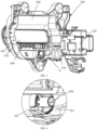
FIG. 1 and FIG. 2 , the flip-in vehicle door handle of the present invention includes ahandle base 100, agrip 200, alinkage mechanism 300 and alinear driving apparatus 400. Thehandle base 100 is provided with agrip installing groove 110, and thegrip 200 is installed in thegrip installing groove 110 and is rotatably connected with thehandle base 100; thelinear driving apparatus 400 is disposed on thehandle base 100 for driving thegrip 200 to rotate; thelinkage mechanism 300 is rotatably installed on thehandle base 100, and a driving input end of thelinkage mechanism 300 is hinged to a linear moving driving end of thelinear driving apparatus 400, and an action output end of thelinkage mechanism 300 is in sliding connection with thegrip 200. When the vehicle door is in a closed state, thegrip 200 covers thegrip installing groove 110 and is flush with an outer door panel; when thelinear driving apparatus 400 is started, thelinear driving apparatus 400 drives thegrip 200 covering thegrip installing groove 110 through thelinkage mechanism 300 to rotate towards an inner side of thehandle base 100, so as to expose the grip installing groove. - Please refer to
FIG. 2 andFIG. 3 , in an embodiment, thelinear driving apparatus 400 includes anelectric actuator 410 and a pushingrod 420. The pushingrod 420 is installed at an output end of theelectric actuator 410. Theelectric actuator 410 outputs a linear driving force, and the pushingrod 420 makes linear reciprocating movement driven by theelectric actuator 410. In the present embodiment, thehandle base 100 is composed of a bottom plate and side plates located around the bottom plate to form a box-shaped cavity. One side of the box-shaped cavity is provided with a firstaccommodating cavity 120 for installing the electric actuator and aslide channel 130 for the pushingrod 420 to slide. The other side of the box-shaped cavity is provided with a secondaccommodating cavity 140, and the secondaccommodating cavity 140 is used to install thelinkage mechanism 300 and thegrip 200. Theelectric actuator 410 is installed in the firstaccommodating cavity 120 through a fastener. Theslide channel 130 is provided at the output end of theelectric actuator 410. Theslide channel 130 is provided transversely along thehandle base 100. The pushingrod 420 makes linear reciprocating movement in theslide channel 130, under the action of theelectric actuator 410. Thelinkage mechanism 300 is installed at a positon of the secondaccommodating cavity 140 corresponding to theslide channel 130. The linear movement of the pushingrod 420 can drive thelinkage mechanism 300 to rotate, thereby driving thegrip 200 to flip toward the inner side of thehandle base 100. Conventional actuator assemblies in the art can be used as theelectric actuator 410 in the present embodiment, the specific structure of which will not be repeated herein. In other embodiments, existing linear driving apparatuses with other structures may be used, for example a driving motor and a turbine worm transmission assembly that cooperates with the driving motor. The turbine worm transmission assembly can convert a rotary movement of the driving motor into a linear movement. - Please refer to
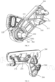
FIG. 5 to FIG. 7 , where the directions indicated by the arrows inFIG. 6 respectively represent rotation directions of the linkage mechanism and the grip. In an embodiment, thelinkage mechanism 300 includes afirst link 310 and asecond link 320. Thefirst link 310 is fixedly connected to thesecond link 320 to form a V-shaped pivot arm. The intersection of thefirst link 310 and thesecond link 320 is rotatably installed to thehandle base 100. In other embodiments, thefirst link 310 and thesecond link 320 may also be an integrated structure. An end of thefirst link 310 away from the intersection of thefirst link 310 and thesecond link 320 is the action output end of thelinkage mechanism 300. The action output end is in sliding connection with thegrip 200. For example, aprotrusion 311 is provided on one side of thefirst link 310 facing thegrip 200, and a clampinggroove 312 is provided inside theprotrusion 311. A corresponding position of thegrip 200 is provided with a first connectingseat 210 that cooperates with the clampinggroove 312. Theprotrusion 311 can be two oppositely arranged bumps, and a gap between the two bumps forms the clampinggroove 312; theprotrusion 311 can also be an integrated structure, with a clampinggroove 312 in the middle thereof. Here, the formation mode of the clampinggroove 312 is not limited. The first connectingseat 210 protrudes from an inner surface of thegrip 200. For example, the first connectingseat 210 includes two spacedseat bodies 211 and across beam 212 connecting the two seat bodies. Preferably, theseat body 211 is in a triangular prism structure, where thecross beam 212 is provided on theseat body 211, and the two ends of thecross beam 212 are connected to the twoseat bodies 211 respectively. Thefirst connection seat 210 and thegrip 200 can be an integrated structure or a separated connection structure. Thecross beam 212 is always clamped in the clampinggroove 212, and a longitudinal size of thecross beam 212 is smaller than an opening size of the clampinggroove 312, so that thecross beam 212 and thegroove 212 form a sliding pair. As thelinkage mechanism 310 rotates, thefirst link 310 slides along thecross beam 212 and at the same time drives thegrip 200 to flip inward. - Please refer to
FIG. 2 ,FIG. 5 , andFIG. 8 toFIG. 10 . The arrow inFIG. 10 indicates a rotation direction of the grip from a closed state to an open state. The end of thesecond link 320 away from the intersection of thefirst link 310 and thesecond link 320 is a power input end of thelinkage mechanism 300, and the power input end is hinged to the pushingrod 420. For example, one end of the pushingrod 420 is fixedly connected to the output end of theelectric actuator 410, and the other end is provided with a clamping groove. Thesecond link 320 is inserted into the clamping groove and is hinged with the pushingrod 420 through a pin. Theelectric actuator 410 drives the pushingrod 420 to make linear movement forward (in a direction away from the electric actuator 410). The pushingrod 420 drives thelinkage mechanism 300 to rotate counterclockwise. As thelinkage mechanism 300 rotates, thefirst link 310 slides along thecross beam 212 of the first connectingseat 210, and at the same time presses thegrip 200 downward to flip thegrip 200 toward the inner side of thehandle base 100, so that thegrip 200 changes from the closed position to the open position. Similarly, when theelectric actuator 410 drives the pushingrod 420 to make a linear movement backward (in a direction towards the electric actuator 410), the pushingrod 420 drives thelinkage mechanism 300 to rotate clockwise. As thelinkage mechanism 300 rotates, thefirst link 310 slides in the opposite direction along thecross beam 212 and at the same time pushes thegrip 200 upward, and thegrip 200 returns from the open position to the closed position. Thelinkage structure 300 adopts a V-shaped pivot arm structure, which can not only ensure the normal rotation movement of the linkage mechanism, but also transmit the linear movement of the pushingrod 420 to thegrip 200 so that it can flip towards the inner side of the handle base and reset to be flush with the outer door panel. - Please refer to
FIG. 3 to FIG.5 , in an embodiment, thelinkage mechanism 300 is rotatably connected to thehandle base 100 through a firstrotating shaft 350. Specifically, the intersection of thefirst link 310 and thesecond link 320 is provided with afirst shaft sleeve 330 and asecond shaft sleeve 340 protruding towards thehandle base 100. Thefirst shaft sleeve 330 is provided on a periphery of thesecond shaft sleeve 340, and forms an annular shaft sleeve with thesecond shaft sleeve 340. Thehandle base 100 is correspondingly provided with athird shaft sleeve 150 protruding from thehandle base 100. An outer diameter of thethird shaft sleeve 150 matches an inner diameter of thesecond shaft sleeve 340 and an inner diameter of thethird shaft sleeve 150 matches an outer diameter of the firstrotating shaft 350, thethird shaft sleeve 150 is inserted into thesecond shaft sleeve 340 to achieve rotational connection through thefirst shaft sleeve 350. Preferably, a torsion spring is also provided at a connection between thelinkage mechanism 300 and thehandle base 100, where the torsion spring is referred to afirst torsion spring 360. Thefirst torsion spring 360 is installed between thefirst shaft sleeve 330 and thesecond shaft sleeve 340, two ends of thefirst torsion spring 360 are connected to thehandle base 100 and thelinkage mechanism 300 respectively. For example, afirst installing groove 331 is provided on a side wall of thefirst shaft sleeve 330, a shaftsleeve fixing seat 151 is provided on a periphery of thethird shaft sleeve 150, and asecond installing groove 152 is provided on a side wall of the shaftsleeve fixing seat 151, thefirst torsion spring 360 is accommodated in space between thefirst shaft sleeve 330 and thesecond shaft sleeve 340, and is sleeved on thesecond shaft sleeve 340. Two ends of thefirst torsion spring 360 are respectively accommodated in the first installing groove 321 and thesecond installing groove 152. The arrangement of thefirst torsion spring 360 allows the linkage mechanism to always maintain resilience and have a tendency to return to an initial position. - Please refer to
FIG. 2 ,FIG. 3 ,FIG. 6 ,FIG. 7 andFIG. 9 , in an embodiment, thegrip installing groove 110 is provided on a bottom plate of thehandle base 100, and located above thelinkage mechanism 300. The inside cavity of thegrip installing groove 110 provides avoiding space for flipping of thegrip 200. Thegrip 200 is installed in thegrip installing groove 110 and is rotatably connected to thehandle base 100 through a secondrotating shaft 170. Specifically, a position of thehandle base 100 corresponding to that below thegrip installing groove 110 is provided with agrip installing seat 160. Thegrip installing seat 160 includes an end portion and a middle portion, and both the end portion and the middle portion are provided with through holes for the rotating shaft to pass through. A second connectingseat 220 is provided on one side of thegrip 200. The second connectingseat 220 is an arched structure, one end of the arched structure is fixed on thegrip 200, and the other end is provided with a through hole for the rotating shaft to pass through. The secondrotating shaft 170 passes through the through holes on thegrip installing seat 160 and the second connectingseat 220 to connect them together. When thelinkage mechanism 300 rotates around the firstrotating shaft 350 driven by the pushingrod 420, thegrip 200 is driven to rotate around the secondrotating shaft 170, so that thegrip 200 can be flipped inward or returned to the initial position by flipping. Preferably, a sealingstructure 230 is provided between thegrip 200 and thegrip installing groove 110. The sealingstructure 230 can be a sealing ring arranged along circumference of thegrip installing groove 110. When thegrip 200 is in a closed state, the sealing ring can seal a gap between thehandle base 100 andgrip 200. - Please refer to
FIG. 3 andFIG.7 , preferably, a torsion spring is provided at the connection between thegrip 200 and thehandle base 100. The torsion spring is referred to as asecond torsion spring 180. Thesecond torsion spring 180 includes twotorque output portions 181 and a connectingportion 182 connecting the twotorque output portions 181. The twotorque output portions 181 are respectively sleeved on the second connectingseats 220 at both ends of thegrip 200, and an output end of thetorque output portion 181 is fixed on the second connectingseat 220, the connectingportion 182 bypasses a bottom of the middle portion of thegrip installing seat 160. The arrangement of thesecond torsion spring 180 allows thegrip 200 to always maintain resilience and have a tendency to return to the initial position. In other embodiments, two torsion springs may also be used, the two torsion springs are respectively sleeved on the second rotating shaft, and the two ends of the torsion spring are respectively fixed on the second connectingseat 220 and thegrip installing seat 160. - Please refer to
FIG. 1, FIG. 2 ,FIG. 8 ,FIG. 10, and FIG. 11 , in an embodiment, anunlatching switch 190 is provided in thehandle base 100, and agrip opening button 240 is provided on an outside of thegrip 200. Theunlatching switch 190 and thegrip opening button 240 are respectively in signal communication with a control module for example DCM (Data Communication Module, Data Communication Module) or BCM (Body Control Module, Body Control Module), to realize the touch unlocking function for vehicle door handle. Theunlatching switch 190 may be an unlatching capacitor or a push-type switch. Theunlatching switch 190 is set at a position that can be touched by the hand after thegrip 200 is opened. Preferably, theunlatching switch 190 is set at a position above a correspondinggrip installing groove 110 so that theunlatching switch 190 can be touched in time after thegrip 200 is opened. The unlatching process of the vehicle door is as follows: when a user approaches the vehicle and touches thegrip opening button 240 on thegrip 200 by a hand, the control module DCM or BCM controls theelectric actuator 410 to start after receiving a signal, so that the pushingrod 420 pushes thelinkage mechanism 300 to rotate, thelinkage mechanism 300 drives thegrip 200 to flip toward an inner side of the vehicle door, exposing thegrip installing groove 110. The user's hand reaches into thegrip installing groove 110 to touch theunlatching switch 190 in thehandle base 100. Theunlatching switch 190 sends a door lock release signal to the control module. The control module sends an unlatching command to the door lock, realizing the unlatching of vehicle door lock. - Please refer to
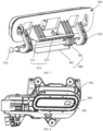
FIG. 3 andFIG. 12 , a hidden-type vehicle door handle of the present invention also includes a gripback cover 500. The gripback cover 500 is covered on the secondaccommodating cavity 140 and is connected to thehandle base 100. For example, apositioning protrusion 141 is provided on a side wall of the secondaccommodating cavity 140. Abuckle 510 that cooperates with thepositioning protrusion 141 is provided at a corresponding position of the grip backcover 500, and the connection between the grip backcover 500 and thehandle base 100 is achieved by cooperating thepositioning protrusion 141 with thebuckle 510. The gripback cover 500 is used to seal thegrip 200 and thelinkage mechanism 300 in the secondaccommodating cavity 140. - Please refer to
FIG. 13 and FIG. 14 , the present invention also provides a vehicle door, which includes anouter door panel 600 and a vehicle door handle installed on theouter door panel 600, where the vehicle door handle is a flip-in vehicle door handle as described above in the present invention. A handle installation hole is provided on theouter door panel 600, a handle base of the flip-in vehicle door handle is fixed inside theouter door panel 600, and the grip can block the handle installation hole. In the initial position, the handle is in a closed state, and thegrip 200 covers thegrip installing groove 110 and is flush with theouter door panel 600; when the handle is opened, thegrip 200 flips toward the inside of the vehicle door to prevent thegrip 200 from popping out from the vehicle door and causing collision damage. - The present invention also provides a vehicle, which includes a vehicle body (not shown in the figure), a vehicle door installed on both sides of the vehicle body, and a vehicle door handle installed on the vehicle door, where the vehicle door is the vehicle door described above in the present invention, and the vehicle door handle is the flip-in vehicle door handle mentioned above in the present invention. The specific structure can be referred to the above description and will not be described in detail here.
- The structures of the vehicle door handle, the vehicle door and the vehicle that are not described in detail in the present invention can all be realized by the existing technology in this field.
- The present invention provides a flip-in vehicle handle, a vehicle door and a vehicle, in which a linkage mechanism is used to convert a linear movement of the linear driving apparatus into a rotary movement, thereby driving the handle to flip toward the inside of the vehicle door to realize the flip-in contraction of the grip, thereby solving the risk of collision and damage caused by the grip popping out of the car. At the same time, the overall Y-direction layout space of the handle is compressed, the structure of the vehicle door handle is optimized and the cost is reduced. Therefore, the present invention effectively overcomes some practical problems in the prior art and has high utilization value and usage significance. Therefore, the present invention effectively overcomes some practical problems in the prior art and has high utilization value and usage significance.
- The above embodiments only illustrate the principles and effects of the present invention, but are not intended to limit the present invention. Those skilled in the art can modify or change the above embodiments without departing from the spirit and scope of the invention. Therefore, all equivalent modifications or changes made by those skilled in the art without departing from the spirit and technical ideas disclosed in the present invention shall fall into the protection scope of the claims of the present invention.
Claims (13)
- A flip-in vehicle door handle, comprising:a handle base, with a grip installing groove provided thereon;a grip, installed in the grip installing groove and is rotatably connected to the handle base;a linear driving apparatus, provided on the handle base;a linkage mechanism, rotatably installed on the handle base; wherein a driving input end of the linkage mechanism is hinged to an output end of the linear driving apparatus, and an action output end of the linkage mechanism is in sliding connection with the grip;wherein when the linear driving apparatus is started, the linkage mechanism is driven to drive the grip blocked on the grip installing groove to rotate toward an inner side of the handle base, so as to expose the grip installing groove.
- The flip-in vehicle door handle according to claim 1, wherein the linear driving apparatus comprises an electric actuator and a pushing rod, the pushing rod is connected to an output end of the electric actuator, and the pushing rod is driven by the electric actuator to perform linear reciprocating movement.
- The flip-in vehicle door handle according to claim 2, wherein the handle base is provided with a first accommodating cavity and a slide channel, the electric actuator is installed in the first accommodating cavity, and the slide channel is provided on a side of the output end of the electric actuator, and the pushing rod makes linear reciprocating movement along the slide channel.
- The flip-in vehicle door handle according to claim 2, wherein the linkage structure comprises a first link and a second link, the first link is fixedly connected to the second link to form a V-shaped pivot arm, an intersection of the first link and the second link is rotatably installed on the handle base, an end of the first link facing away from the intersection is in sliding connection with the grip, and an end of the second link facing away from the intersection is hinged to the pushing rod.
- The flip-in vehicle door handle according to claim 4, wherein a first shaft sleeve and a second shaft sleeve protruding towards a side of the handle base are provided at the intersection of the first link and the second link, the first shaft sleeve is provided on a periphery of the second shaft sleeve, a third shaft sleeve is correspondingly provided on the handle base, and the third shaft sleeve is inserted into the second shaft sleeve and fixed by a first rotating shaft.
- The flip-in vehicle door handle according to claim 5, wherein a first torsion spring is provided at a connection between the linkage mechanism and the handle base, and the first torsion spring is sleeved on the second shaft sleeve, two ends of the first torsion spring are respectively fixed to the first shaft sleeve and the handle base.
- The flip-in vehicle door handle according to claim 4, wherein a clamping groove is provided at a position where the first link is connected to the grip, and a first connecting seat cooperated with the clamping groove is provided on the grip, the grip is in sliding connection with the first link by a cooperation of the first connecting seat and the clamping groove.
- The flip-in vehicle door handle according to claim 1, wherein a grip installing seat is provided below a position of the handle base corresponding to the grip installing groove, second connecting seats are provided at both ends of the grip, the grip installing seat is rotatably connected to the second connecting seat through a second rotating shaft.
- The flip-in vehicle door handle according to claim 8, wherein a second torsion spring is provided on the second rotating shaft, and the second torsion spring is sleeved on the second rotating shaft, and two torsion output ends of the second torsion spring are respectively connected to the second connecting seat.
- The flip-in vehicle door handle according to claim 1, wherein the flip-in vehicle door handle further comprises an unlatching switch, the unlatching switch is provided above the grip installing groove and is electrically connected to a control module.
- The flip-in vehicle door handle according to claim 1, wherein a sealing apparatus is provided between the grip and the grip installing groove, and the sealing apparatus is circumferentially provided along an outer edge of the grip installing groove.
- A vehicle door, comprising an outer door panel and the flip-in vehicle door handle according to claim 1, and the flip-in vehicle door handle is installed on the outer door panel.
- A vehicle, comprising the flip-in vehicle door handle according to claim 1 or the vehicle door according to claim 12.
Applications Claiming Priority (2)
| Application Number | Priority Date | Filing Date | Title |
|---|---|---|---|
| CN202211094538.4A CN115559621B (en) | 2022-09-02 | 2022-09-02 | Inward-turning door handle, door and vehicle |
| PCT/CN2023/116536 WO2024046472A1 (en) | 2022-09-02 | 2023-09-01 | Flip-in vehicle door handle, vehicle door, and vehicle |
Publications (2)
| Publication Number | Publication Date |
|---|---|
| EP4582657A1 true EP4582657A1 (en) | 2025-07-09 |
| EP4582657A4 EP4582657A4 (en) | 2026-01-07 |
Family
ID=84738464
Family Applications (1)
| Application Number | Title | Priority Date | Filing Date |
|---|---|---|---|
| EP23859499.8A Pending EP4582657A4 (en) | 2022-09-02 | 2023-09-01 | FOLDABLE VEHICLE DOOR HANDLE, VEHICLE DOOR AND VEHICLE |
Country Status (5)
| Country | Link |
|---|---|
| US (1) | US20250092722A1 (en) |
| EP (1) | EP4582657A4 (en) |
| JP (1) | JP7771436B2 (en) |
| CN (1) | CN115559621B (en) |
| WO (1) | WO2024046472A1 (en) |
Families Citing this family (2)
| Publication number | Priority date | Publication date | Assignee | Title |
|---|---|---|---|---|
| CN115559621B (en) * | 2022-09-02 | 2025-06-03 | 浙江极氪智能科技有限公司 | Inward-turning door handle, door and vehicle |
| SI26493A (en) * | 2023-04-13 | 2024-10-30 | Griffing, D.O.O. | Handle system for house doors |
Family Cites Families (25)
| Publication number | Priority date | Publication date | Assignee | Title |
|---|---|---|---|---|
| JPS58121958U (en) * | 1982-02-12 | 1983-08-19 | 三菱自動車工業株式会社 | Vehicle door handle device |
| US5560659A (en) * | 1994-11-04 | 1996-10-01 | Adac Plastics, Inc. | Door handle assembly |
| KR100535084B1 (en) * | 2004-04-14 | 2005-12-07 | 현대자동차주식회사 | Door inside handle assembly for automobile |
| DE102006027474A1 (en) * | 2006-06-12 | 2007-12-13 | Huf Hülsbeck & Fürst Gmbh & Co. Kg | Actuator II |
| KR100931160B1 (en) * | 2007-12-17 | 2009-12-10 | 현대자동차주식회사 | Hidden Type Outside Handle |
| JP5619073B2 (en) * | 2012-05-18 | 2014-11-05 | 株式会社ホンダロック | Unlatch device for vehicle door |
| GB2517348B (en) * | 2012-09-25 | 2015-09-23 | Jaguar Land Rover Ltd | Retractable handle arrangement |
| JP6009325B2 (en) * | 2012-11-12 | 2016-10-19 | アイシン精機株式会社 | Door handle device |
| DE102013109930A1 (en) * | 2013-09-10 | 2015-03-12 | BROSE SCHLIEßSYSTEME GMBH & CO. KG | Drive arrangement for the motorized adjustment of a cover flap arrangement |
| KR101592642B1 (en) * | 2013-12-17 | 2016-02-11 | 현대자동차주식회사 | Door inside handle apparatus with pull handle |
| US9518410B2 (en) * | 2014-05-01 | 2016-12-13 | AISIN Technical Center of America, Inc. | Flush mounted vehicle handle |
| JP6686391B2 (en) * | 2015-11-30 | 2020-04-22 | アイシン精機株式会社 | Vehicle handle device |
| DE102017126168B4 (en) * | 2016-12-09 | 2023-04-06 | Toyota Motor Engineering & Manufacturing North America, Inc. | FLUSH AUTOMATIC SLIDING DOOR HANDLE |
| JP7083625B2 (en) * | 2017-11-13 | 2022-06-13 | 株式会社アルファ | Vehicle door open / close operation device |
| KR102681921B1 (en) * | 2018-08-30 | 2024-07-04 | 현대자동차 주식회사 | Inertia Linkage and Retractable outside door handle assembly for vehicle using the same |
| DE102019207935A1 (en) * | 2019-05-29 | 2020-12-03 | Witte Automotive Gmbh | Door handle assembly and door |
| CN110206419A (en) * | 2019-07-05 | 2019-09-06 | 重庆熠美实业发展有限公司 | A kind of hidden intelligent automobile external opening door handle |
| DE102021204182A1 (en) * | 2020-04-28 | 2021-11-11 | Magna Mirrors Of America, Inc. | EXTERIOR VEHICLE DOOR HANDLE ASSEMBLY WITH LIGHT PROJECTION AND GESTURE DETECTION |
| US20220090420A1 (en) * | 2020-09-22 | 2022-03-24 | Canoo Technologies Inc. | Door Handles |
| CN112576122A (en) * | 2020-12-29 | 2021-03-30 | 无锡忻润汽车安全系统有限公司 | Hidden handle turning-in mechanism |
| CN113090142A (en) * | 2021-03-17 | 2021-07-09 | 黄冈格罗夫氢能汽车有限公司 | Hidden handle of hydrogen energy automobile door |
| CN216406465U (en) * | 2021-12-07 | 2022-04-29 | 重庆熠美实业发展有限公司 | Hidden outwardly opened door handle of car |
| CN216974484U (en) * | 2021-12-28 | 2022-07-15 | 比亚迪股份有限公司 | Door handle assembly, door handle assembly and vehicle |
| CN115162866B (en) * | 2022-07-13 | 2024-05-03 | 宁波华德汽车零部件有限公司 | Concealed electric inner-folding automobile outer door handle |
| CN115559621B (en) * | 2022-09-02 | 2025-06-03 | 浙江极氪智能科技有限公司 | Inward-turning door handle, door and vehicle |
-
2022
- 2022-09-02 CN CN202211094538.4A patent/CN115559621B/en active Active
-
2023
- 2023-09-01 JP JP2024570453A patent/JP7771436B2/en active Active
- 2023-09-01 WO PCT/CN2023/116536 patent/WO2024046472A1/en not_active Ceased
- 2023-09-01 EP EP23859499.8A patent/EP4582657A4/en active Pending
-
2024
- 2024-11-29 US US18/963,865 patent/US20250092722A1/en active Pending
Also Published As
| Publication number | Publication date |
|---|---|
| EP4582657A4 (en) | 2026-01-07 |
| WO2024046472A1 (en) | 2024-03-07 |
| US20250092722A1 (en) | 2025-03-20 |
| CN115559621B (en) | 2025-06-03 |
| JP2025520109A (en) | 2025-07-01 |
| JP7771436B2 (en) | 2025-11-17 |
| CN115559621A (en) | 2023-01-03 |
Similar Documents
| Publication | Publication Date | Title |
|---|---|---|
| US20250092722A1 (en) | Flip-in vehicle door handle, vehicle door, and vehicle | |
| KR100445035B1 (en) | Door lock drive unit | |
| US11578513B2 (en) | Handle device for a motor vehicle door | |
| EP1914774B1 (en) | Switching mechanism for air circuit breaker | |
| US20220136291A1 (en) | Flip cover actuation assembly, and refueling port or charging port flip cover assembly comprising same | |
| US11891841B2 (en) | Opening and closing device of vehicle sliding door | |
| CN115891629A (en) | Flip unit for opening at vehicle and vehicle | |
| CN114435120A (en) | Actuating assembly and oil filler hole or charging hole flip assembly | |
| KR100956483B1 (en) | Device for opening and shutting glove box of car | |
| CN218234725U (en) | Child lock and car | |
| CN216767044U (en) | Electric suction lock for automobile and unlocking device thereof | |
| CN106158531B (en) | The closing spring loading device of breaker | |
| KR20110101617A (en) | Switchgear of car glove box | |
| CN215949216U (en) | Electronic flip device of header board upper cover | |
| KR20160133597A (en) | Closing spring charging device of circuit breaker | |
| JP2018188870A (en) | Lock device for vehicle | |
| KR102474828B1 (en) | Swing motion open and closed type charging door device for electric vehicle with rotating handle structure | |
| JP7316101B2 (en) | door handle structure | |
| CN116252869A (en) | charging port door | |
| CN103179813B (en) | Containing device and electronic device using same | |
| CN114961458A (en) | Actuating device for a flap mounted movably on a component | |
| US11603696B2 (en) | Apparatus for automatically opening and closing trunk lid | |
| CN114899023B (en) | A dual power transfer switch with a locking mechanism | |
| CN217260342U (en) | Locking structure and charging port device | |
| CN223539464U (en) | Operating mechanism of changeover switch |
Legal Events
| Date | Code | Title | Description |
|---|---|---|---|
| STAA | Information on the status of an ep patent application or granted ep patent |
Free format text: STATUS: THE INTERNATIONAL PUBLICATION HAS BEEN MADE |
|
| PUAI | Public reference made under article 153(3) epc to a published international application that has entered the european phase |
Free format text: ORIGINAL CODE: 0009012 |
|
| STAA | Information on the status of an ep patent application or granted ep patent |
Free format text: STATUS: REQUEST FOR EXAMINATION WAS MADE |
|
| 17P | Request for examination filed |
Effective date: 20241127 |
|
| AK | Designated contracting states |
Kind code of ref document: A1 Designated state(s): AL AT BE BG CH CY CZ DE DK EE ES FI FR GB GR HR HU IE IS IT LI LT LU LV MC ME MK MT NL NO PL PT RO RS SE SI SK SM TR |
|
| DAV | Request for validation of the european patent (deleted) | ||
| DAX | Request for extension of the european patent (deleted) | ||
| A4 | Supplementary search report drawn up and despatched |
Effective date: 20251208 |
|
| RIC1 | Information provided on ipc code assigned before grant |
Ipc: E05B 85/10 20140101AFI20251202BHEP Ipc: E05B 81/76 20140101ALI20251202BHEP Ipc: E05B 85/18 20140101ALI20251202BHEP Ipc: E05B 81/28 20140101ALI20251202BHEP |
|
| GRAP | Despatch of communication of intention to grant a patent |
Free format text: ORIGINAL CODE: EPIDOSNIGR1 |
|
| STAA | Information on the status of an ep patent application or granted ep patent |
Free format text: STATUS: GRANT OF PATENT IS INTENDED |
|
| RIC1 | Information provided on ipc code assigned before grant |
Ipc: E05B 85/10 20140101AFI20260221BHEP Ipc: E05B 81/76 20140101ALI20260221BHEP Ipc: E05B 85/18 20140101ALI20260221BHEP Ipc: E05B 81/28 20140101ALI20260221BHEP |
|
| INTG | Intention to grant announced |
Effective date: 20260306 |
|
| GRAS | Grant fee paid |
Free format text: ORIGINAL CODE: EPIDOSNIGR3 |
|
| GRAA | (expected) grant |
Free format text: ORIGINAL CODE: 0009210 |
|
| STAA | Information on the status of an ep patent application or granted ep patent |
Free format text: STATUS: THE PATENT HAS BEEN GRANTED |