EP4582393A2 - Fluid treatment module - Google Patents
Fluid treatment module Download PDFInfo
- Publication number
- EP4582393A2 EP4582393A2 EP25177209.1A EP25177209A EP4582393A2 EP 4582393 A2 EP4582393 A2 EP 4582393A2 EP 25177209 A EP25177209 A EP 25177209A EP 4582393 A2 EP4582393 A2 EP 4582393A2
- Authority
- EP
- European Patent Office
- Prior art keywords
- fluid treatment
- light source
- pipe
- inlet
- source module
- Prior art date
- Legal status (The legal status is an assumption and is not a legal conclusion. Google has not performed a legal analysis and makes no representation as to the accuracy of the status listed.)
- Pending
Links
Images







Classifications
-
- C—CHEMISTRY; METALLURGY
- C02—TREATMENT OF WATER, WASTE WATER, SEWAGE, OR SLUDGE
- C02F—TREATMENT OF WATER, WASTE WATER, SEWAGE, OR SLUDGE
- C02F1/00—Treatment of water, waste water, or sewage
- C02F1/30—Treatment of water, waste water, or sewage by irradiation
- C02F1/32—Treatment of water, waste water, or sewage by irradiation with ultraviolet light
- C02F1/325—Irradiation devices or lamp constructions
-
- A—HUMAN NECESSITIES
- A61—MEDICAL OR VETERINARY SCIENCE; HYGIENE
- A61L—METHODS OR APPARATUS FOR STERILISING MATERIALS OR OBJECTS IN GENERAL; DISINFECTION, STERILISATION OR DEODORISATION OF AIR; CHEMICAL ASPECTS OF BANDAGES, DRESSINGS, ABSORBENT PADS OR SURGICAL ARTICLES; MATERIALS FOR BANDAGES, DRESSINGS, ABSORBENT PADS OR SURGICAL ARTICLES
- A61L9/00—Disinfection, sterilisation or deodorisation of air
- A61L9/16—Disinfection, sterilisation or deodorisation of air using physical phenomena
- A61L9/18—Radiation
- A61L9/20—Ultraviolet radiation
-
- A—HUMAN NECESSITIES
- A61—MEDICAL OR VETERINARY SCIENCE; HYGIENE
- A61L—METHODS OR APPARATUS FOR STERILISING MATERIALS OR OBJECTS IN GENERAL; DISINFECTION, STERILISATION OR DEODORISATION OF AIR; CHEMICAL ASPECTS OF BANDAGES, DRESSINGS, ABSORBENT PADS OR SURGICAL ARTICLES; MATERIALS FOR BANDAGES, DRESSINGS, ABSORBENT PADS OR SURGICAL ARTICLES
- A61L9/00—Disinfection, sterilisation or deodorisation of air
- A61L9/16—Disinfection, sterilisation or deodorisation of air using physical phenomena
- A61L9/18—Radiation
- A61L9/20—Ultraviolet radiation
- A61L9/205—Ultraviolet radiation using a photocatalyst or photosensitiser
-
- F—MECHANICAL ENGINEERING; LIGHTING; HEATING; WEAPONS; BLASTING
- F21—LIGHTING
- F21V—FUNCTIONAL FEATURES OR DETAILS OF LIGHTING DEVICES OR SYSTEMS THEREOF; STRUCTURAL COMBINATIONS OF LIGHTING DEVICES WITH OTHER ARTICLES, NOT OTHERWISE PROVIDED FOR
- F21V29/00—Protecting lighting devices from thermal damage; Cooling or heating arrangements specially adapted for lighting devices or systems
- F21V29/50—Cooling arrangements
- F21V29/502—Cooling arrangements characterised by the adaptation for cooling of specific components
- F21V29/503—Cooling arrangements characterised by the adaptation for cooling of specific components of light sources
-
- F—MECHANICAL ENGINEERING; LIGHTING; HEATING; WEAPONS; BLASTING
- F21—LIGHTING
- F21V—FUNCTIONAL FEATURES OR DETAILS OF LIGHTING DEVICES OR SYSTEMS THEREOF; STRUCTURAL COMBINATIONS OF LIGHTING DEVICES WITH OTHER ARTICLES, NOT OTHERWISE PROVIDED FOR
- F21V29/00—Protecting lighting devices from thermal damage; Cooling or heating arrangements specially adapted for lighting devices or systems
- F21V29/50—Cooling arrangements
- F21V29/70—Cooling arrangements characterised by passive heat-dissipating elements, e.g. heat-sinks
-
- A—HUMAN NECESSITIES
- A61—MEDICAL OR VETERINARY SCIENCE; HYGIENE
- A61L—METHODS OR APPARATUS FOR STERILISING MATERIALS OR OBJECTS IN GENERAL; DISINFECTION, STERILISATION OR DEODORISATION OF AIR; CHEMICAL ASPECTS OF BANDAGES, DRESSINGS, ABSORBENT PADS OR SURGICAL ARTICLES; MATERIALS FOR BANDAGES, DRESSINGS, ABSORBENT PADS OR SURGICAL ARTICLES
- A61L2209/00—Aspects relating to disinfection, sterilisation or deodorisation of air
- A61L2209/10—Apparatus features
-
- C—CHEMISTRY; METALLURGY
- C02—TREATMENT OF WATER, WASTE WATER, SEWAGE, OR SLUDGE
- C02F—TREATMENT OF WATER, WASTE WATER, SEWAGE, OR SLUDGE
- C02F2201/00—Apparatus for treatment of water, waste water or sewage
- C02F2201/32—Details relating to UV-irradiation devices
- C02F2201/322—Lamp arrangement
- C02F2201/3222—Units using UV-light emitting diodes [LED]
-
- C—CHEMISTRY; METALLURGY
- C02—TREATMENT OF WATER, WASTE WATER, SEWAGE, OR SLUDGE
- C02F—TREATMENT OF WATER, WASTE WATER, SEWAGE, OR SLUDGE
- C02F2201/00—Apparatus for treatment of water, waste water or sewage
- C02F2201/32—Details relating to UV-irradiation devices
- C02F2201/322—Lamp arrangement
- C02F2201/3227—Units with two or more lamps
-
- C—CHEMISTRY; METALLURGY
- C02—TREATMENT OF WATER, WASTE WATER, SEWAGE, OR SLUDGE
- C02F—TREATMENT OF WATER, WASTE WATER, SEWAGE, OR SLUDGE
- C02F2201/00—Apparatus for treatment of water, waste water or sewage
- C02F2201/32—Details relating to UV-irradiation devices
- C02F2201/322—Lamp arrangement
- C02F2201/3228—Units having reflectors, e.g. coatings, baffles, plates, mirrors
-
- C—CHEMISTRY; METALLURGY
- C02—TREATMENT OF WATER, WASTE WATER, SEWAGE, OR SLUDGE
- C02F—TREATMENT OF WATER, WASTE WATER, SEWAGE, OR SLUDGE
- C02F2303/00—Specific treatment goals
- C02F2303/04—Disinfection
-
- C—CHEMISTRY; METALLURGY
- C02—TREATMENT OF WATER, WASTE WATER, SEWAGE, OR SLUDGE
- C02F—TREATMENT OF WATER, WASTE WATER, SEWAGE, OR SLUDGE
- C02F2305/00—Use of specific compounds during water treatment
- C02F2305/10—Photocatalysts
-
- F—MECHANICAL ENGINEERING; LIGHTING; HEATING; WEAPONS; BLASTING
- F21—LIGHTING
- F21Y—INDEXING SCHEME ASSOCIATED WITH SUBCLASSES F21K, F21L, F21S and F21V, RELATING TO THE FORM OR THE KIND OF THE LIGHT SOURCES OR OF THE COLOUR OF THE LIGHT EMITTED
- F21Y2115/00—Light-generating elements of semiconductor light sources
- F21Y2115/10—Light-emitting diodes [LED]
Definitions
- Embodiments of the present invention relate to a fluid treatment module.
- Embodiments of the present invention provide a device capable of efficiently treating a fluid, such as air or water.
- a fluid treatment module includes: a pipe providing a flow channel in which fluid flows, the pipe having an inlet and an outlet; a light source module including a substrate and at least one light emitting diode disposed on an upper surface of the substrate and emitting light into the pipe to treat the fluid; a reflector disposed inside the pipe to reflect the light emitted from the light source module and having higher reflectivity with respect to the light than the pipe; and a heat dissipation plate contacting a rear surface of the substrate to dissipate heat from the light source module.
- At least one of the inlet and the outlet is provided in plural to allow a flow speed and a flow direction of the fluid flowing into the pipe to be controlled, and the heat dissipation plate has higher thermal conductivity than the substrate.
- the heat dissipation plate may have a larger area than the substrate.
- the heat dissipation plate may be formed of a metal.
- the inlet and the outlet may be provided in different numbers.
- the inlet and the outlet may be disposed at different end sides.
- the inlet and the outlet may be connected to the pipe in the same direction, with a center of the pipe disposed therebetween, when viewed in the longitudinal direction of the pipe.
- the inlet and the outlet may be connected to the pipe in different directions when viewed in the longitudinal direction of the pipe.
- the fluid treatment module may further include a reflector disposed inside the pipe and reflecting light emitted from the light source module.
- the reflector may have higher reflectivity with respect to the light than the pipe.
- the reflector may include a first reflector disposed on an inner wall of the pipe and a second reflector disposed on the substrate of the light source module.
- the second reflector may have an opening exposing the light emitting diode and an inner surface of the opening may be an inclined surface.
- the reflector may be formed of a porous material and may have a reflectivity of 80% or more.
- the inlet may be provided as a pair and the outlet may be provided singularly.
- the inlet and the outlet may have the same diameter or different diameters.
- the fluid treatment module may be employed by a water supply device, which includes a reservoir receiving water and a water treatment device connected to the reservoir and treating the water.
- Embodiments of the present invention provide a fluid treatment module having high treatment efficiency and high reliability.
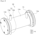
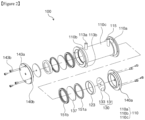
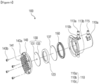
- Figure 1 is a perspective view of a fluid treatment module according to an embodiment of the present invention and Figure 2 is an exploded perspective view of the fluid treatment module according to the embodiment of the present invention.
- Figure 3 is a perspective longitudinal sectional view of the fluid treatment module shown in Figure 1 .
- fluid treatment module refers to an object to be treated using the fluid treatment module and may include water (especially running water) or air.
- treatment of the fluid includes, for example, sterilizing, purifying, and deodorizing the fluid through the fluid treatment module.
- treatment of the fluid is not limited thereto and may include other possible treatment carried out using the fluid treatment module described below.
- a fluid treatment module 100 includes a pipe 110, in which fluid flows, and a light source module 130 emitting light towards the fluid in the pipe 110.
- the pipe 110 extends in one direction and has a shape open at opposite ends thereof.
- the pipe 110 may include a body 110c, which extends in a longitudinal direction thereof, and a first end 110a and a second end 110b disposed in the longitudinal direction of the body 110c.
- the body 110c has a hollow pipe shape having a predetermined diameter.
- the first end 110a and the second end 110b are connected to the opposite ends of the body 110c and may have the same diameter as or a larger diameter than the body 110c.
- the pipe 110 provides an interior space, that is, a flow channel, in which the fluid flows while being treated.
- a direction in which the pipe 110 extends will be referred to as an extension direction of the pipe 110 or the longitudinal direction of the pipe 110.
- the pipe 110 may have a substantially cylindrical shape.
- a cross-section crossing a longitudinal direction of the cylindrical shape has a circular shape.
- the pipe 110 is not limited thereto and may have various cross-sectional shapes, for example, an elliptical shape, a rectangular shape, a semicircular shape, and the like.
- the pipe 110 may be formed of a material having high reflectivity and/or a metal having high thermal conductivity.
- the pipe 110 may be formed of a material having high reflectivity, such as stainless steel, aluminum, magnesium oxide, and the like, or may be formed of a material having high thermal conductivity, such as stainless steel, aluminum, silver, gold, copper, and alloys thereof. Metals having high thermal conductivity can effectively discharge heat from the pipe 110.
- the pipe 110 is not limited thereto and may be formed of a material that transmits at least part of light emitted from the light source module 130 such that the light can reach the fluid inside the pipe 110, when the light source module 130 is disposed outside the pipe 110.
- the material capable of transmitting light may include various types of polymer resins, quartz, glass, and the like.
- the entirety of the pipe 110 or a portion of the pipe 110 adjacent to the light source module 130 may be formed of a transparent material to allow the light emitted from the light source module 130 to reach the fluid.
- the pipe 110 is provided with an inlet 113 through which the fluid enter the pipe 110 and an outlet 115 through which the fluid is discharged therefrom after treatment.
- the inlet 113 and/or the outlet 115 may be provided to at least one region of the pipe 110 selected from among the body 110c, the first end 110a, and the second end 110b.
- the inlet 113 is connected to the pipe 110.
- a connecting direction of the inlet 113 may be different from the extension direction of the pipe 110.
- the connecting direction of the inlet 113 may be inclined or perpendicular to the extension direction of the pipe 110 such that the fluid enters the pipe 110 in a direction inclined or perpendicular thereto and flows in the extension direction of the pipe 110.
- the fluid flowing into the pipe 110 through inlet 113 is a fluid to be treated in the pipe 110, for example, an object that requires sterilization, purification, or deodorization treatment.
- the outlet 115 may be disposed at a location separated from the inlet 113 and may be connected to the pipe 110.
- a connecting direction of the outlet 115 may be inclined or perpendicular to the extension direction of the pipe 110 such that the fluid can be discharged from the pipe 110 in a direction inclined or perpendicular thereto after flowing in the extension direction of the pipe 110.
- the fluid discharged from the pipe 110 through the outlet 115 is a fluid treated in the pipe 110, for example, an object subjected to sterilization, purification, or deodorization treatment.
- the inlet 113 when viewed in a direction perpendicular to the longitudinal direction of the pipe 110, the inlet 113 may be provided to at least one end side selected from among the opposite ends of the pipe 110 and the outlet 115 may also be provided to at least one end side selected from among the opposite ends of the pipe 110.
- each of the inlet 113 and the outlet 115 may be provided to at least one end side selected from among the first end 110a and the second end 110b or may be provided to both the first end 110a side and the second end 110b side.
- the inlet 113 may be provided to the first end 110a side and the outlet 115 may be provided to the second end 110b side.
- the inlet 113 may be provided to the second end 110b side and the outlet 115 may be provided to the first end 110a side.
- the locations of the inlet 113 and the outlet 115 are not limited thereto.
- the inlet 113 and/or the outlet 115 may be disposed at a center of the pipe 110 instead of the opposite ends thereof.
- the inlet 113 and the outlet 115 may be disposed in various ways when viewed in the longitudinal direction of the pipe 110.
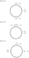
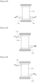
- Figure 4a to Figure 4c are sectional views of some components of the fluid treatment module according to the embodiment of the present invention, particularly illustrating the pipe 110, the inlet 113, and the outlet 115, in which each of the inlet 113 and the outlet 115 is provided singularly.
- reference numeral 121 indicates a first reflector.
- the inlet 113 and the outlet 115 may be connected to the pipe 110 to face each other with the center of the pipe 110 disposed therebetween, when viewed in a cross-section perpendicular to the extension direction of the pipe 110. That is, the inlet 113 and the outlet 115 may be disposed at symmetric locations with the center of the pipe 110 disposed therebetween. However, it should be understood that the inlet 113 and the outlet 115 are not required to be completely symmetric about the center of the pipe 110.
- the inlet 113 and the outlet 115 may be connected to the pipe 110 at the same side with reference to the center of the pipe 110.
- the inlet 113 and the outlet 115 may be separated from the pipe 110. That is, the inlet 113 and the outlet 115 may be collinearly or non-collinearly disposed in the extension direction of the pipe 110. Alternatively, the inlet 113 and the outlet 115 may be disposed to overlap each other. Referring to Figure 4c , the inlet 113 and the outlet 115 may be connected to the pipe 110 to be perpendicular to each other.
- the locations of the inlet 113 and the outlet 115 may be changed depending upon the kind of apparatus adopting the fluid treatment module.
- the locations of the inlet and the outlet may be set in various ways depending upon a fluid treatment amount or a degree of fluid sterilization required by the apparatus.
- each of the inlet 113 and the outlet 115 is provided singularly in the drawings, it should be understood that this structure is provided for illustration of a positional relationship between the inlet 113 and the outlet 115. Accordingly, when one of the inlet 113 and the outlet 115 is provided in plural, the inlets 113 or the outlets 115 may be individually disposed at different locations. For example, for the fluid treatment module including two inlets 113, that is, a first inlet 113a and a second inlet 113b, the first inlet 113a is disposed at a side opposite the outlet 115 and the second inlet 113b may be disposed at the same side as the outlet 115 when viewed in the extension direction of the pipe 110.
- the inlet 113 and the outlet 115 may have a circular or elliptical cross-section, without being limited thereto.
- the inlet 113 and the outlet 115 may have various shapes, for example, a polygonal shape.
- the cross-section of each of the inlet 113 and the outlet 115 may be taken in the extension direction of the inlet 113 or in a direction crossing a direction in which the flow channel is formed.
- the inlet 113 and/or the outlet 115 may be provided with a separate pipe.
- the separate pipe may be connected to the inlet 113 and the outlet 115 through a nozzle.
- the nozzle may be coupled to the inlet 113 and/or the outlet 115 in various ways, for example, by screw coupling.
- the flow amount or speed of the fluid supplied through the inlet 113 and the flow amount or speed of the fluid discharged through the outlet 115 may be controlled depending upon the number and diameter of the inlets 113 and the outlets 115.
- the inlet 113 and the outlet 115 may have the same diameter or different diameters. According to the embodiment, although the inlet 113 having the same diameter as the outlet 115 can provide good fluid treatment efficiency, the inlet 113 having a larger diameter than the outlet 115 can provide better fluid treatment efficiency.
- the inlet 113 and the outlet 115 may be provided in plural.
- the inlet 113 may be provided in plural and the outlet 115 may be provided singularly.
- the inlet 113 may be provided singularly and the outlet 115 may be provided in plural or both the inlet 113 and the outlet 115 may be provided in plural.
- the inlets 113 and the outlets 115 may be provided in one-to-one correspondence.
- the fluid treatment device including two inlets 113 and one outlet 115 can have improved fluid treatment efficiency.
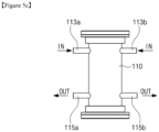
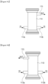
- Figure 5a to Figure 5c are side sectional views of the fluid treatment module according to the embodiment of the present invention, particularly illustrating the pipe, the inlet and the outlet thereof.
- each of the inlet and the outlet may be provided in various numbers.
- the fluid treatment module may include multiple inlets (that is, a first inlet 113a and a second inlet 113b) and a single outlet 115, as shown in Figure 5a ; a single inlet 113 and multiple outlets (that is, a first outlet 115a and a second outlet 115b), as shown in Figure 5b ; or multiple inlets (that is, a first inlet 113a and a second inlet 113b) and multiple outlets (that is, a first outlet 115a and a second outlet 115b), as shown in Figure 5c .
- the first and second inlets 113a, 113b when viewed in the direction perpendicular to the extension direction of the pipe 110, the first and second inlets 113a, 113b may be provided to the second end 110b side and the outlet 115 may be provided to the first end 110a side, and when viewed in the extension direction of the pipe 110, the first inlet 113a may be disposed at an opposite side to the outlet 115, with the center of the pipe 110 disposed therebetween, and the second inlet 113b may be disposed at the same side as the outlet 115 with reference to the center of the pipe 110.
- the light source module 130 emits light and may be disposed at one side selected from among the first end 110a and the second end 110b of the pipe 110.
- the light source module 130 is provided to both the first end 110a and the second end 110b by way of example.
- the location of the light source module 130 is not limited thereto and may be provided to one of the opposite ends of the pipe 110 in the longitudinal direction thereof. It should be understood that the location of the light source module 130 in this embodiment is provided for illustration only and is not to be construed in any way as limiting the present invention and that the light source module 130 may be disposed at any location so long as the light source module 130 can irradiate the interior of the pipe 10.
- the light source module 130 may be disposed outside the pipe 110, without being limited thereto.
- the light source module 130 may include a substrate 131 and a light emitting diode 133 mounted on the substrate 131.
- the substrate 131 may be provided in various forms, for example, in the form of a disk having a diameter corresponding to the pipe 10. Multiple light emitting diodes 133 may be arranged in a predetermined direction on the substrate 131.
- the substrate 31 may be provided with an opening through which a wire is connected to the light emitting diode 133 to supply power thereto.
- the light emitting diodes 133 may emit light in the same wavelength band or in different wavelength bands. For example, in one embodiment, all of the light emitting diodes 133 may emit UV light having the same or similar wavelength. In another embodiment, some light emitting diodes 133 may emit light in some UV wavelength bands and the other light emitting diodes 133 may emit light in other UV wavelength bands.
- the light emitting diodes 133 may be arranged in various sequences. For example, light emitting diodes 133 emitting light in a first wavelength band and light emitting diodes 133 emitting light in a second wavelength band different from the first wavelength band may be alternately arranged.
- the light source module 130 may emit light in various wavelength bands.
- the light source module 130 may emit light in the visible spectrum, light in the UV spectrum, or light in other wavelength bands.
- light emitted from the light source module 130 may have various wavelengths depending upon the type of fluid to be treated or the type of object to be treated (for example, germs, bacteria, and the like).
- the light source module 130 may emit light having a germicidal wavelength.
- the light source module 130 may emit light in the UV spectrum.
- the light source module 130 may emit light in the wavelength band of about 100 nm to about 420 nm, which is germicidal to microorganisms.
- the light source module 130 may emit light in the wavelength band of about 100 nm to about 280 nm. In another embodiment, the light source module 130 may emit light in the wavelength band of about 180 nm to about 280 nm. In a further embodiment, the light source module 130 may emit light in the wavelength band of about 250 nm to about 260 nm.
- UV light in the above wavelength bands has high germicidal efficacy. For example, irradiation with UV light at an intensity of 100 ⁇ W/cm 2 can kill about 99% of bacteria, such as Escherichia coli, Diphtheria bacillus, and Dysentery bacillus.
- UV light in the above wavelength bands can kill bacteria that cause food poisoning, such as pathogenic Escherichia coli, Staphylococcus aureus, Salmonella Weltevreden, S. Typhimurium, Enterococcus faecalis, Bacillus cereus, Pseudomonas aeruginosa, Vibrio parahaemolyticus, Listeria monocytogenes, Yersinia enterocolitica, Clostridium perfringens, Clostridium botulinum, Campylobacter jejuni, or Enterobacter sakazakii.
- bacteria that cause food poisoning such as pathogenic Escherichia coli, Staphylococcus aureus, Salmonella Weltevreden, S. Typhimurium, Enterococcus faecalis, Bacillus cereus, Pseudomonas aeruginosa, Vibrio parahaemolyticus, Listeria monocytogenes, Yersin
- the light source module 130 may emit light having various wavelengths and at least part of the light source module 130 may include a material that causes a catalytic reaction in response to light emitted from the light source module 130.
- a photocatalytic layer formed of a photocatalytic material may be disposed on the entirety or a portion of an inner surface and/or an outer surface of the pipe 10 according to the present invention.
- the photocatalytic layer may be disposed in any region so long as the light emitted from the light source module 130 can reach the region.
- a photocatalyst refers to a material causing a catalytic reaction with light emitted from a light source.
- the photocatalyst can react with light in various wavelength bands depending on substances constituting the photocatalyst.
- a material causing photocatalytic reaction with light in the UV wavelength band among various wavelength bands may be used.
- the photocatalyst is not limited thereto and other photocatalysts having the same or similar mechanism may be used depending on light emitted from the light source.
- the photocatalyst is activated by UV light to cause chemical reaction, thereby decomposing various pollutants and bacteria in the fluid, which contacts the photocatalyst, through redox reaction.
- the fluid treatment module 100 may further include a drive circuit connected to the light source module 130 and an interconnect portion connecting the drive circuit to the light source module 130.
- the drive circuit may supply electric power to at least one light source module 130.
- the drive circuit may be provided to the fluid treatment module 100 having two light source modules 130 to independently supply electric power to each of the light source modules 130. Accordingly, the light source modules 130 may be selectively driven such that all of the two light source modules 130 can be turned on or off, or one light source module 130 can be turned on, with the other light source module 130 turned off.
- the transmissive window 137 serves to protect the substrate 131 and the light source and may be formed of a transparent, electrically insulating material. However, it should be understood that the present invention is not limited thereto and the transmissive window 137 may be formed of various other materials.
- the transmissive window 37 may be formed of quartz or an organic polymer.
- the organic polymer since the wavelength of light absorbed by/transmitted through the organic polymer depends on the type of monomers for the organic polymer, a method of forming the organic polymer, and conditions in which the organic polymer material is formed, the organic polymer may be selected in consideration of wavelengths of light emitted from the light sources.
- the substrate 131 and the transmissive window 137 may correspond to the pipe 110 in terms of shape and size.
- the elastic material forming the sealing members 151a, 151b may include a silicone resin, it will be understood that the present invention is not limited thereto and the sealing members 151a, 151b may be formed of any other suitable material.
- natural or synthetic rubber or other elastic organic polymers may be used as the elastic material.
- the first heat dissipation plate 140a is disposed at the first end 110a of the pipe 110 to be fastened to the pipe 110.
- the first heat dissipation plate 140a is formed with stepped portions having different outer diameters to be inserted into and fastened to the pipe 110.
- a portion of the first heat dissipation plate 140a facing the first end 110a of the pipe 110 has an outer diameter corresponding to the inner diameter of the pipe 110.
- the pipe 110 and the second heat dissipation plate 140b may be provided with fastening members for coupling the pipe 110 to the second heat dissipation plate 140b.
- the pipe 110 and the second heat dissipation plate 140b may be provided with fastening holes 143a such that the pipe 110 can be coupled to the second heat dissipation plate 140b by coupling fastening bolts 143b to the fastening holes 143a of the pipe 110 and the second heat dissipation plate 140b.
- the first and second heat dissipation plates 140a, 140b are used not only as heat dissipation members for dissipation of heat generated from the light source module 130, but also as tools for encapsulating the pipe 110, that is, as the first and second caps.
- encapsulating members for encapsulating the pipe 110 may be further provided as separate components from the first and second heat dissipation plates 140a, 140b.
- the separate encapsulating members may also be formed of a material having high thermal conductivity to allow efficient dissipation of heat from the first and second heat dissipation plates 140a, 140b.
- the fluid treatment module according to the embodiments of the present invention may be modified in various shapes without departing from the concept of the present invention.
- a fluid treatment module 100 includes a pipe 110, in which fluid flows, and a light source module 130 emitting light towards the fluid in the pipe 110.
- the pipe 110 extends in one direction and has a shape closed at one end thereof and open at the other end thereof.
- the first end 110a has a closed shape having no inlet and the second end 110b has an open shape.
- the pipe 110 is provided with an inlet 113 through which the fluid enter the pipe 110 and an outlet 115 through which the fluid is discharged therefrom after treatment.
- the inlet 113 may be provided to an open end side, that is, to the second end 110b side
- the outlet 115 may be provided to a closed end side, that is, to the first end 110a side.
- the inlet 113 may be provided in plural, for example, as a first inlet 113a and a second inlet 113b. In this embodiment, both the first inlet 113a and the second inlet 113b may be provided to the second end 110b side.
- the light source module 130 supplies light suitable for treatment of the fluid.
- the light source module 130 may be disposed at the second end 110b side among the first end 110a and the second end 110b of the pipe 110.
- the light source module 130 is not disposed at the first end 110a side, which does not include an opening.
- the light source module 130 may include a substrate 131 and a light emitting diode 133 mounted on the substrate 131.
- a transmissive window 137 may be further disposed between the light source module 130 and a fluid treatment space inside the pipe 110 to transmit light emitted from the light source module 130 to the interior of the pipe 110.
- the heat dissipation plate 140 is formed of a material having higher thermal conductivity than the substrate 131 of the light source module 130, and serves to discharge heat, which is generated from the light source module 130, particularly from the light emitting diode 133, and is transferred through the substrate 131. To this end, the heat dissipation plate 140 directly contacts the rear surface of the substrate 131 of the light source module 130.
- the heat dissipation plate 140 may have a larger area than the substrate 131 to allow efficient dissipation of heat from the substrate 131.
- the substrate 131 is disposed inside the pipe 110 and may have a diameter corresponding to the pipe 110, and the heat dissipation plate 140 may have a larger diameter than the substrate 131.
- the heat dissipation plate 140 may have a larger diameter than the body 110c of the pipe 110. Since the heat dissipation plate 140 may disposed at the second end 110b of the pipe 110, the heat dissipation plate 140 can be formed to protrude from the second end 110b of the pipe 110 and can be easily formed to have a larger diameter.
- the heat dissipation plate 140 may include a protrusion 141 protruding from a surface thereof to allow easy dissipation of heat as much as possible.
- the protrusion 141 may be provided in plural, whereby the surface area of the heat dissipation plate 140 can be remarkably increased thereby, as compared with the heat dissipation plate 140 not including the protrusions 141. As the surface area of the heat dissipation plate 140 is increased, a contact area between the heat dissipation plate 140 and external air is increased, thereby enabling efficient dissipation of heat from the heat dissipation plate 140.
- the protrusions 141 have a plate shape extending in one direction and may be spaced apart from each other.
- the protrusions 141 are not limited thereto and may have any shape without limitation so long as the protrusions can increase the surface area of the heat dissipation plate 140.
- the heat dissipation plate 140 including the protrusions 141 may be provided as an integrated structure. With this structure, the heat dissipation plate 140 allows easier heat transfer than a structure wherein the heat dissipation plate 140 is not integrally formed therewith.
- the heat dissipation plate 140 enables easier dissipation of heat from a light source. As a result, the light source is prevented from being deteriorated due to heat from the light source, thereby providing a stable sterilization effect of the fluid treatment module 100 while improving reliability thereof.
- the body 110c is blocked at the first end 110a thereof and the fluid enters the pipe through one side of the pipe and is discharged from the pipe through the other side thereof, an eddy can be easily generated at a blocked portion inside the body 110c. A time that the fluid stays in the body 100c is increased by the eddy. As a result, the exposure time of the fluid to light emitted from the light source module 130 is sufficiently increased and the fluid treatment effect is also finally improved.
- the body 110c may have a shorter length than the body according to the above embodiment. When the body 110c has a short distance, an eddy can be more easily generated inside the body 110c.
- the fluid treatment module 100 can omit a reflector reflecting light to travel inside the pipe 110, for example, the reflector surrounding the inner wall of the pipe 110, unlike the above embodiment.
- the reflector 120 does not include the first reflector 121 (see Figure 2 and Figure 3 ) inside the pipe 110 and may include only the second reflector 123 disposed near the light source module 130.
- the second reflector 123 is disposed on the substrate 131 along the periphery of the mounting region of the light emitting diodes 133.
- the second reflector 123, the light emitting diode 133 has an opening exposing the mounting region of the light emitting diodes 133 and is disposed on the substrate 131 in a ring shape penetrated through upper and lower portions thereof.
- the fluid treatment module 100 may be provided with a sealing member to tightly fasten the pipe 10 to the heat dissipation plate 140 while preventing the fluid from leaking out of the fluid treatment module.
- the fluid treatment module 100 according to the embodiment shown in Figure 2 and Figure 3 is provided with two sealing members, the fluid treatment module 100 according to this embodiment may be provided with a single sealing member.
- the sealing member 150 is disposed near the fluid treatment space while surrounding an end of the transmissive window 137 in an angled-C shape.
- the heat dissipation plate 140 may be used as a cap encapsulating the second end 110b of the pipe 110. Accordingly, in this embodiment, the heat dissipation plate 140 may have a fastening portion coupled to the pipe 110.
- the pipe 110 and the heat dissipation plate 140 may be provided with fastening members for coupling the pipe 110 to the heat dissipation plate 140.
- Figure 13 is a schematic view of an apparatus, for example, a water treatment apparatus, adopting the fluid treatment module according to the fluid treatment module according to the embodiment of the present invention.
Landscapes
- Health & Medical Sciences (AREA)
- Life Sciences & Earth Sciences (AREA)
- Engineering & Computer Science (AREA)
- Chemical & Material Sciences (AREA)
- Toxicology (AREA)
- Organic Chemistry (AREA)
- Water Supply & Treatment (AREA)
- Environmental & Geological Engineering (AREA)
- Hydrology & Water Resources (AREA)
- General Health & Medical Sciences (AREA)
- Veterinary Medicine (AREA)
- Public Health (AREA)
- Animal Behavior & Ethology (AREA)
- Epidemiology (AREA)
- General Engineering & Computer Science (AREA)
- Chemical Kinetics & Catalysis (AREA)
- Physical Water Treatments (AREA)
- Apparatus For Disinfection Or Sterilisation (AREA)
- Instantaneous Water Boilers, Portable Hot-Water Supply Apparatuses, And Control Of Portable Hot-Water Supply Apparatuses (AREA)
Abstract
Description
- Embodiments of the present invention relate to a fluid treatment module.
- In recent years, as pollution caused by industrialization is increasing, interest in the environment is increasing together with health consciousness. Accordingly, with increasing demand for clean water or clean air, various related products such as water purifiers and air/water purifiers capable of providing clean water and clean air are being developed.
- Embodiments of the present invention provide a device capable of efficiently treating a fluid, such as air or water.
- In accordance with one aspect of the present invention, a fluid treatment module includes: a pipe providing a flow channel in which fluid flows, the pipe having an inlet and an outlet; a light source module including a substrate and at least one light emitting diode disposed on an upper surface of the substrate and emitting light into the pipe to treat the fluid; a reflector disposed inside the pipe to reflect the light emitted from the light source module and having higher reflectivity with respect to the light than the pipe; and a heat dissipation plate contacting a rear surface of the substrate to dissipate heat from the light source module. At least one of the inlet and the outlet is provided in plural to allow a flow speed and a flow direction of the fluid flowing into the pipe to be controlled, and the heat dissipation plate has higher thermal conductivity than the substrate.
- In one embodiment, the heat dissipation plate may have a larger area than the substrate.
- In one embodiment, the heat dissipation plate may be formed of a metal.
- In one embodiment, the inlet and the outlet may be provided in different numbers.
- In one embodiment, the pipe may include a body extending in a longitudinal direction thereof and first and second ends disposed in the longitudinal direction of the body.
- In one embodiment, the heat dissipation plate may have a larger diameter than the body.
- In one embodiment, the inlet and the outlet may be disposed at different end sides.
- In one embodiment, the inlet and the outlet may be connected to the pipe in the same direction, with a center of the pipe disposed therebetween, when viewed in the longitudinal direction of the pipe.
- In one embodiment, the inlet and the outlet may be connected to the pipe in different directions when viewed in the longitudinal direction of the pipe.
- In one embodiment, the fluid treatment module may further include a reflector disposed inside the pipe and reflecting light emitted from the light source module.
- In one embodiment, the reflector may have higher reflectivity with respect to the light than the pipe.
- In one embodiment, the reflector may include a first reflector disposed on an inner wall of the pipe and a second reflector disposed on the substrate of the light source module. In one embodiment, the second reflector may have an opening exposing the light emitting diode and an inner surface of the opening may be an inclined surface.
- In one embodiment, the reflector may be formed of a porous material and may have a reflectivity of 80% or more.
- In one embodiment, the inlet may be provided as a pair and the outlet may be provided singularly.
- In one embodiment, the inlet and the outlet may have the same diameter or different diameters.
- In one embodiment, the fluid treatment module may be employed by a water supply device, which includes a reservoir receiving water and a water treatment device connected to the reservoir and treating the water.
- Embodiments of the present invention provide a fluid treatment module having high treatment efficiency and high reliability.
-
-
Figure 1 is a perspective view of a fluid treatment module according to an embodiment of the present invention. -
Figure 2 is an exploded perspective view of the fluid treatment module according to the embodiment of the present invention. -
Figure 3 is a perspective longitudinal sectional view of the fluid treatment module shown inFigure 1 . -
Figure 4a to Figure 4c are sectional views of some components of the fluid treatment module according to the embodiment of the present invention, particularly illustrating a pipe, an inlet and an outlet thereof. -
Figure 5a to Figure 5c are side sectional views of the fluid treatment module according to the embodiment of the present invention, particularly illustrating the pipe, the inlet and the outlet thereof. -
Figure 6 is an exploded perspective view of a fluid treatment module according to an embodiment of the present invention. -
Figure 7 is a perspective longitudinal sectional view of the fluid treatment module according to the embodiment of the present invention. -
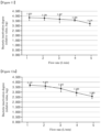
Figure 8a and Figure 8b are graphs depicting a fluid treatment effect depending upon the presence of a reflector, andFigure 8C is a side sectional view of a fluid treatment module used in experiments ofFigure 8a and Figure 8b . -
Figure 9a to Figure 9f are side views of fluid treatment modules each provided with an inlet and an outlet through various modifications. -
Figure 10a to Figure 10f are graphs depicting fluid treatment effects of the fluid treatment modules shown inFigure 9a to Figure 9f , respectively. -
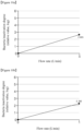
Figure 11 is a graph depicting sterilization efficiency depending upon a flow rate of a fluid flowing in the pipe of the fluid treatment module according to the embodiment of the present invention. -
Figure 12a andFigure 12b are graphs depicting sterilization efficiency depending upon the flow rate of the fluid flowing in the pipe of the fluid treatment module according to the embodiment of the present invention. -
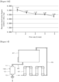
Figure 13 is a schematic view of a water purifier adopting the fluid treatment module according to the embodiment of the present invention. - Hereinafter, exemplary embodiments of the present invention will be described in detail with reference to the accompanying drawings so as to fully convey the spirit of the present invention to those skilled in the art.
-
Figure 1 is a perspective view of a fluid treatment module according to an embodiment of the present invention andFigure 2 is an exploded perspective view of the fluid treatment module according to the embodiment of the present invention.Figure 3 is a perspective longitudinal sectional view of the fluid treatment module shown inFigure 1 . - One embodiment of the present invention relates to a fluid treatment module. In the embodiment, the term "fluid" refers to an object to be treated using the fluid treatment module and may include water (especially running water) or air. In one embodiment, treatment of the fluid includes, for example, sterilizing, purifying, and deodorizing the fluid through the fluid treatment module. However, treatment of the fluid is not limited thereto and may include other possible treatment carried out using the fluid treatment module described below.
- Referring to
Figure 1 to Figure 3 , afluid treatment module 100 according to one embodiment includes apipe 110, in which fluid flows, and alight source module 130 emitting light towards the fluid in thepipe 110. Thepipe 110 extends in one direction and has a shape open at opposite ends thereof. Thepipe 110 may include abody 110c, which extends in a longitudinal direction thereof, and afirst end 110a and asecond end 110b disposed in the longitudinal direction of thebody 110c. Thebody 110c has a hollow pipe shape having a predetermined diameter. Thefirst end 110a and thesecond end 110b are connected to the opposite ends of thebody 110c and may have the same diameter as or a larger diameter than thebody 110c. Thepipe 110 provides an interior space, that is, a flow channel, in which the fluid flows while being treated. Hereinafter, a direction in which thepipe 110 extends will be referred to as an extension direction of thepipe 110 or the longitudinal direction of thepipe 110. - In the embodiment, the
pipe 110 may have a substantially cylindrical shape. In this case, a cross-section crossing a longitudinal direction of the cylindrical shape has a circular shape. However, it should be understood that thepipe 110 is not limited thereto and may have various cross-sectional shapes, for example, an elliptical shape, a rectangular shape, a semicircular shape, and the like. - The
pipe 110 may be formed of a material having high reflectivity and/or a metal having high thermal conductivity. For example, thepipe 110 may be formed of a material having high reflectivity, such as stainless steel, aluminum, magnesium oxide, and the like, or may be formed of a material having high thermal conductivity, such as stainless steel, aluminum, silver, gold, copper, and alloys thereof. Metals having high thermal conductivity can effectively discharge heat from thepipe 110. - However, the
pipe 110 is not limited thereto and may be formed of a material that transmits at least part of light emitted from thelight source module 130 such that the light can reach the fluid inside thepipe 110, when thelight source module 130 is disposed outside thepipe 110. The material capable of transmitting light may include various types of polymer resins, quartz, glass, and the like. For example, the entirety of thepipe 110 or a portion of thepipe 110 adjacent to thelight source module 130 may be formed of a transparent material to allow the light emitted from thelight source module 130 to reach the fluid. - The
pipe 110 is provided with aninlet 113 through which the fluid enter thepipe 110 and anoutlet 115 through which the fluid is discharged therefrom after treatment. Theinlet 113 and/or theoutlet 115 may be provided to at least one region of thepipe 110 selected from among thebody 110c, thefirst end 110a, and thesecond end 110b. - As shown in
Figure 1 andFigure 2 , theinlet 113 is connected to thepipe 110. A connecting direction of theinlet 113 may be different from the extension direction of thepipe 110. In one embodiment, the connecting direction of theinlet 113 may be inclined or perpendicular to the extension direction of thepipe 110 such that the fluid enters thepipe 110 in a direction inclined or perpendicular thereto and flows in the extension direction of thepipe 110. The fluid flowing into thepipe 110 throughinlet 113 is a fluid to be treated in thepipe 110, for example, an object that requires sterilization, purification, or deodorization treatment. - The
outlet 115 may be disposed at a location separated from theinlet 113 and may be connected to thepipe 110. In one embodiment, a connecting direction of theoutlet 115 may be inclined or perpendicular to the extension direction of thepipe 110 such that the fluid can be discharged from thepipe 110 in a direction inclined or perpendicular thereto after flowing in the extension direction of thepipe 110. The fluid discharged from thepipe 110 through theoutlet 115 is a fluid treated in thepipe 110, for example, an object subjected to sterilization, purification, or deodorization treatment. - In one embodiment, when viewed in a direction perpendicular to the longitudinal direction of the
pipe 110, theinlet 113 may be provided to at least one end side selected from among the opposite ends of thepipe 110 and theoutlet 115 may also be provided to at least one end side selected from among the opposite ends of thepipe 110. In other words, in the embodiment, assuming the opposite ends of thepipe 110 in the longitudinal direction are referred to as thefirst end 110a and thesecond end 110b, respectively, each of theinlet 113 and theoutlet 115 may be provided to at least one end side selected from among thefirst end 110a and thesecond end 110b or may be provided to both thefirst end 110a side and thesecond end 110b side. For example, as shown in the drawings, theinlet 113 may be provided to thefirst end 110a side and theoutlet 115 may be provided to thesecond end 110b side. Alternatively, theinlet 113 may be provided to thesecond end 110b side and theoutlet 115 may be provided to thefirst end 110a side. However, it should be understood that the locations of theinlet 113 and theoutlet 115 are not limited thereto. For example, theinlet 113 and/or theoutlet 115 may be disposed at a center of thepipe 110 instead of the opposite ends thereof. - In the embodiment, the
inlet 113 and theoutlet 115 may be disposed in various ways when viewed in the longitudinal direction of thepipe 110.Figure 4a to Figure 4c are sectional views of some components of the fluid treatment module according to the embodiment of the present invention, particularly illustrating thepipe 110, theinlet 113, and theoutlet 115, in which each of theinlet 113 and theoutlet 115 is provided singularly. InFigure 4a to Figure 4c ,reference numeral 121 indicates a first reflector. - Referring to
Figure 4a , theinlet 113 and theoutlet 115 may be connected to thepipe 110 to face each other with the center of thepipe 110 disposed therebetween, when viewed in a cross-section perpendicular to the extension direction of thepipe 110. That is, theinlet 113 and theoutlet 115 may be disposed at symmetric locations with the center of thepipe 110 disposed therebetween. However, it should be understood that theinlet 113 and theoutlet 115 are not required to be completely symmetric about the center of thepipe 110. Referring toFigure 4b , theinlet 113 and theoutlet 115 may be connected to thepipe 110 at the same side with reference to the center of thepipe 110. In this case, as shown in the drawings, theinlet 113 and theoutlet 115 may be separated from thepipe 110. That is, theinlet 113 and theoutlet 115 may be collinearly or non-collinearly disposed in the extension direction of thepipe 110. Alternatively, theinlet 113 and theoutlet 115 may be disposed to overlap each other. Referring toFigure 4c , theinlet 113 and theoutlet 115 may be connected to thepipe 110 to be perpendicular to each other. - The locations of the
inlet 113 and theoutlet 115 may be changed depending upon the kind of apparatus adopting the fluid treatment module. In particular, the locations of the inlet and the outlet may be set in various ways depending upon a fluid treatment amount or a degree of fluid sterilization required by the apparatus. - Although each of the
inlet 113 and theoutlet 115 is provided singularly in the drawings, it should be understood that this structure is provided for illustration of a positional relationship between theinlet 113 and theoutlet 115. Accordingly, when one of theinlet 113 and theoutlet 115 is provided in plural, theinlets 113 or theoutlets 115 may be individually disposed at different locations. For example, for the fluid treatment module including twoinlets 113, that is, afirst inlet 113a and asecond inlet 113b, thefirst inlet 113a is disposed at a side opposite theoutlet 115 and thesecond inlet 113b may be disposed at the same side as theoutlet 115 when viewed in the extension direction of thepipe 110. - Referring again to
Figure 1 to Figure 3 , in the embodiment, theinlet 113 and theoutlet 115 may have a circular or elliptical cross-section, without being limited thereto. Alternatively, theinlet 113 and theoutlet 115 may have various shapes, for example, a polygonal shape. Here, the cross-section of each of theinlet 113 and theoutlet 115 may be taken in the extension direction of theinlet 113 or in a direction crossing a direction in which the flow channel is formed. - Although not shown in the drawings, the
inlet 113 and/or theoutlet 115 may be provided with a separate pipe. The separate pipe may be connected to theinlet 113 and theoutlet 115 through a nozzle. The nozzle may be coupled to theinlet 113 and/or theoutlet 115 in various ways, for example, by screw coupling. - In one embodiment, the flow amount or speed of the fluid supplied through the
inlet 113 and the flow amount or speed of the fluid discharged through theoutlet 115 may be controlled depending upon the number and diameter of theinlets 113 and theoutlets 115. To this end, in one embodiment, theinlet 113 and theoutlet 115 may have the same diameter or different diameters. According to the embodiment, although theinlet 113 having the same diameter as theoutlet 115 can provide good fluid treatment efficiency, theinlet 113 having a larger diameter than theoutlet 115 can provide better fluid treatment efficiency. - Further, in one embodiment, at least one of the
inlet 113 and theoutlet 115 may be provided in plural. For example, theinlet 113 may be provided in plural and theoutlet 115 may be provided singularly. Alternatively, theinlet 113 may be provided singularly and theoutlet 115 may be provided in plural or both theinlet 113 and theoutlet 115 may be provided in plural. For the fluid treatment device includingmultiple inlets 113 andmultiple outlets 115, theinlets 113 and theoutlets 115 may be provided in one-to-one correspondence. In particular, in one embodiment, the fluid treatment device including twoinlets 113 and oneoutlet 115 can have improved fluid treatment efficiency. -
Figure 5a to Figure 5c are side sectional views of the fluid treatment module according to the embodiment of the present invention, particularly illustrating the pipe, the inlet and the outlet thereof. - In one embodiment, as shown in
Figure 5a to Figure 5c , each of the inlet and the outlet may be provided in various numbers. For example, the fluid treatment module may include multiple inlets (that is, afirst inlet 113a and asecond inlet 113b) and asingle outlet 115, as shown inFigure 5a ; asingle inlet 113 and multiple outlets (that is, afirst outlet 115a and asecond outlet 115b), as shown inFigure 5b ; or multiple inlets (that is, afirst inlet 113a and asecond inlet 113b) and multiple outlets (that is, afirst outlet 115a and asecond outlet 115b), as shown inFigure 5c . - Although two inlets and two outlets are illustrated by way of example, it should be understood that the present invention is not limited thereto and a greater number of inlets or outlets may be provided.
- Referring again to
Figure 1 to Figure 3 , for the fluid treatment module including twoinlets 113 according to the embodiment, when viewed in the direction perpendicular to the extension direction of thepipe 110, the first andsecond inlets second end 110b side and theoutlet 115 may be provided to thefirst end 110a side, and when viewed in the extension direction of thepipe 110, thefirst inlet 113a may be disposed at an opposite side to theoutlet 115, with the center of thepipe 110 disposed therebetween, and thesecond inlet 113b may be disposed at the same side as theoutlet 115 with reference to the center of thepipe 110. - The fluid treatment effect depending upon the number and diameter of the
inlets 113 and theoutlets 115 will be described below. - The
light source module 130 supplies light suitable for treatment of the fluid. Thelight source module 130 may be disposed at various locations adjacent to the fluid to emit light for treatment (for example, sterilization, purification, or deodorization) of the fluid. - The
light source module 130 emits light and may be disposed at one side selected from among thefirst end 110a and thesecond end 110b of thepipe 110. In this embodiment, thelight source module 130 is provided to both thefirst end 110a and thesecond end 110b by way of example. However, it should be understood that the location of thelight source module 130 is not limited thereto and may be provided to one of the opposite ends of thepipe 110 in the longitudinal direction thereof. It should be understood that the location of thelight source module 130 in this embodiment is provided for illustration only and is not to be construed in any way as limiting the present invention and that thelight source module 130 may be disposed at any location so long as thelight source module 130 can irradiate the interior of the pipe 10. Unlike in the drawings, thelight source module 130 may be disposed outside thepipe 110, without being limited thereto. - The
light source module 130 may include asubstrate 131 and alight emitting diode 133 mounted on thesubstrate 131. Thesubstrate 131 may be provided in various forms, for example, in the form of a disk having a diameter corresponding to the pipe 10. Multiplelight emitting diodes 133 may be arranged in a predetermined direction on thesubstrate 131. The substrate 31 may be provided with an opening through which a wire is connected to thelight emitting diode 133 to supply power thereto. - For the
light source module 130 including multiplelight emitting diodes 133, thelight emitting diodes 133 may emit light in the same wavelength band or in different wavelength bands. For example, in one embodiment, all of thelight emitting diodes 133 may emit UV light having the same or similar wavelength. In another embodiment, somelight emitting diodes 133 may emit light in some UV wavelength bands and the otherlight emitting diodes 133 may emit light in other UV wavelength bands. - When the
light emitting diodes 133 emit light in different wavelength bands, thelight emitting diodes 133 may be arranged in various sequences. For example,light emitting diodes 133 emitting light in a first wavelength band and light emittingdiodes 133 emitting light in a second wavelength band different from the first wavelength band may be alternately arranged. - The
light source module 130 may emit light in various wavelength bands. Thelight source module 130 may emit light in the visible spectrum, light in the UV spectrum, or light in other wavelength bands. In one embodiment, light emitted from thelight source module 130 may have various wavelengths depending upon the type of fluid to be treated or the type of object to be treated (for example, germs, bacteria, and the like). In particular, when the fluid is to be sterilized, thelight source module 130 may emit light having a germicidal wavelength. For example, thelight source module 130 may emit light in the UV spectrum. In one embodiment, thelight source module 130 may emit light in the wavelength band of about 100 nm to about 420 nm, which is germicidal to microorganisms. In one embodiment, thelight source module 130 may emit light in the wavelength band of about 100 nm to about 280 nm. In another embodiment, thelight source module 130 may emit light in the wavelength band of about 180 nm to about 280 nm. In a further embodiment, thelight source module 130 may emit light in the wavelength band of about 250 nm to about 260 nm. UV light in the above wavelength bands has high germicidal efficacy. For example, irradiation with UV light at an intensity of 100 µW/cm2 can kill about 99% of bacteria, such as Escherichia coli, Diphtheria bacillus, and Dysentery bacillus. In addition, UV light in the above wavelength bands can kill bacteria that cause food poisoning, such as pathogenic Escherichia coli, Staphylococcus aureus, Salmonella Weltevreden, S. Typhimurium, Enterococcus faecalis, Bacillus cereus, Pseudomonas aeruginosa, Vibrio parahaemolyticus, Listeria monocytogenes, Yersinia enterocolitica, Clostridium perfringens, Clostridium botulinum, Campylobacter jejuni, or Enterobacter sakazakii. - In one embodiment, the
light source module 130 may emit light having various wavelengths and at least part of thelight source module 130 may include a material that causes a catalytic reaction in response to light emitted from thelight source module 130. For example, a photocatalytic layer formed of a photocatalytic material may be disposed on the entirety or a portion of an inner surface and/or an outer surface of the pipe 10 according to the present invention. The photocatalytic layer may be disposed in any region so long as the light emitted from thelight source module 130 can reach the region. - A photocatalyst refers to a material causing a catalytic reaction with light emitted from a light source. The photocatalyst can react with light in various wavelength bands depending on substances constituting the photocatalyst. In one embodiment, a material causing photocatalytic reaction with light in the UV wavelength band among various wavelength bands may be used. However, the photocatalyst is not limited thereto and other photocatalysts having the same or similar mechanism may be used depending on light emitted from the light source.
- The photocatalyst is activated by UV light to cause chemical reaction, thereby decomposing various pollutants and bacteria in the fluid, which contacts the photocatalyst, through redox reaction.
- Although not shown in the drawings, the
fluid treatment module 100 according to the embodiment may further include a drive circuit connected to thelight source module 130 and an interconnect portion connecting the drive circuit to thelight source module 130. The drive circuit may supply electric power to at least onelight source module 130. For example, the drive circuit may be provided to thefluid treatment module 100 having twolight source modules 130 to independently supply electric power to each of thelight source modules 130. Accordingly, thelight source modules 130 may be selectively driven such that all of the twolight source modules 130 can be turned on or off, or onelight source module 130 can be turned on, with the otherlight source module 130 turned off. - A
transmissive window 137 may be further disposed between thelight source module 130 and a fluid treatment space inside thepipe 110 to transmit light emitted from thelight source module 130 to the interior of thepipe 110. - The
transmissive window 137 serves to protect thesubstrate 131 and the light source and may be formed of a transparent, electrically insulating material. However, it should be understood that the present invention is not limited thereto and thetransmissive window 137 may be formed of various other materials. For example, the transmissive window 37 may be formed of quartz or an organic polymer. Here, since the wavelength of light absorbed by/transmitted through the organic polymer depends on the type of monomers for the organic polymer, a method of forming the organic polymer, and conditions in which the organic polymer material is formed, the organic polymer may be selected in consideration of wavelengths of light emitted from the light sources. For example, organic polymers, such as poly (poly methyl methacrylate; PMMA), polyvinyl alcohol (PVA), polypropylene (PP), and low-density polyethylene (PE), absorb little or no UV light, whereas polymer resins such as polyester can absorb UV light. - In this embodiment, the
substrate 131 and thetransmissive window 137 may correspond to thepipe 110 in terms of shape and size. - A heat dissipation plate is disposed on an outer surface of the
light source module 130 to dissipate heat generated from thelight source module 130. In one embodiment, in a structure wherein thelight source modules 130 are provided to the opposite ends of thepipe 110, a firstheat dissipation plate 140a and a secondheat dissipation plate 140b are disposed outside the twolight source modules 130, respectively. - The first and second
heat dissipation plates substrate 131 of thelight source module 130, and serve to discharge heat, which is generated from thelight source module 130, particularly from thelight emitting diode 133, and is transferred through thesubstrate 131. To this end, each of the first and secondheat dissipation plates substrate 131 of thelight source module 130. - As the material having higher thermal conductivity than the
substrate 131 of thelight source module 130, various materials may be used. For thesubstrate 131 formed of a metal, each of the first and secondheat dissipation plates substrate 131. For example, when thesubstrate 131 is formed of stainless steel, the first and secondheat dissipation plates heat dissipation plates substrate 131, instead of being limited to a particular one. - In one embodiment, the first and second
heat dissipation plates substrate 131 to allow efficient dissipation of heat from thesubstrate 131. Thesubstrate 131 is disposed inside thepipe 110 and may have a diameter corresponding to thepipe 110, and the first and secondheat dissipation plates substrate 131. In addition, each of the first and secondheat dissipation plates body 110c of thepipe 110. Since the first and secondheat dissipation plates pipe 110, that is, at the first andsecond ends heat dissipation plates pipe 110 and can be easily formed to have larger diameters. - In the embodiment, the first and second
heat dissipation plates fluid treatment module 100 while improving reliability thereof. - In one embodiment, the
fluid treatment module 100 may be provided with areflector 120 in addition to thesubstrate 131 and thelight emitting diodes 133 to improve fluid treatment efficiency by reflecting light emitted from thelight emitting diodes 133 to travel inside thepipe 110. - The
reflector 120 has higher reflectivity than thepipe 110. For example, when thepipe 110 is formed of a material, such as stainless steel, thereflector 120 is formed of a material having higher reflectivity than the stainless steel. In one embodiment, thereflector 120 formed of a material having higher reflectivity than thepipe 100 may be disposed inside thepipe 110 to increase reflectivity with respect to light traveling inside thepipe 110. Increase in reflectivity of light results in improvement in fluid treatment efficiency through efficient reflection of light inside thepipe 110. - The
reflector 120 may be formed of a material that reflects light emitted from thelight source module 130. Thereflector 120 may be formed of a material reflecting 80% or more of light emitted from thelight source module 130 in one embodiment, 90% or more of the light in another embodiment, and 99% or more of the light in a further embodiment. - The
reflector 120 may be formed of a material having high reflectivity to maximize efficiency in extraction of light emitted from the light emittingdiode chip 133. For example, thereflector 120 may be formed of a material having roughness to improve reflection and scattering of light on the surface thereof. Alternatively, thereflector 120 may be formed of a material having a porous surface. Although there are various porous materials having surface roughness, the reflector according to one embodiment may be formed of a polymer resin, for example, PTFE. However, it should be understood that thereflector 120 is not limited thereto and may be formed of other materials so long as thereflector 120 can secure sufficient reflectivity. For example, thereflector 120 may be formed of aluminum and/or an aluminum alloy. Alternatively, thereflector 120 may be formed of a material having high reflectivity, for example, various metals, such as silver, gold, tin, copper, chromium, nickel, molybdenum, titanium, and the like, and/or alloys thereof. - The
reflector 120 may include afirst reflector 121 disposed inside thepipe 110 and asecond reflector 123 disposed near thelight source module 130. Thefirst reflector 121 and thesecond reflector 123 may be formed of the same material or different materials. For example, both thefirst reflector 121 and thesecond reflector 123 may be formed of polytetrafluoroethylene (PTFE). Alternatively, thefirst reflector 121 may be formed of PTFE and thesecond reflector 123 may be formed of an aluminum alloy. - The
first reflector 121 covers the inner surface of thepipe 110. For thepipe 110 having a cylindrical shape, thefirst reflector 121 may be formed to cover the entirety of a cylindrical inner wall of thepipe 110. Here, thefirst reflector 121 may be present or absent on portions of the inner wall of thepipe 110 corresponding to theinlet 113 and theoutlet 115. In the embodiment, the inner wall of thepipe 110 may be substantially prevented from being exposed by thefirst reflector 121, which is disposed on the inner wall of thepipe 110 so as to cover a light reaching region as much as possible. - The
second reflector 123 is disposed on thesubstrate 131 along the periphery of a mounting region of thelight emitting diodes 133. Thesecond reflector 123 serves to reflect light emitted from thelight emitting diodes 133 to travel toward each region in thepipe 110. To this end, thesecond reflector 123 has an opening exposing the mounting region of thelight emitting diodes 133 and is disposed on thesubstrate 131 in a ring shape penetrated through upper and lower portions thereof. - According to one embodiment, the
second reflector 123 may have an inner surface facing the opening, an outer surface facing the outside, and a bottom surface adjoining an upper surface of thesubstrate 131. The inner surface is at least partially inclined with respect to the upper surface of thesubstrate 131. With this structure, the opening of thesecond reflector 123 has a width gradually increasing from the upper surface of thesubstrate 131 in an upward direction. In other words, thesecond reflector 123 has an inner diameter gradually increasing from the upper surface of thesubstrate 131 in the upward direction. In a cross-section of thesecond reflector 123, an inclined side may be linear or curved and may have an inclination set at various angles in consideration of the number oflight emitting diodes 133, a beam angle of thelight emitting diode 133, and the intensity of light emitted from thelight emitting diode 133, and the like. - The
fluid treatment module 100 according to this embodiment may be provided with one ormore sealing members heat dissipation plates - In one embodiment, the sealing
members first end 110a of thepipe 110 and between a second cap and thesecond end 110b of thepipe 110, respectively. Each of the sealingmembers substrate 131 and thetransmissive window 137 and between thetransmissive window 137 and a stepped portion inside thepipe 110, respectively. The first and second sealing members 150a, 150b serve to tightly fasten thepipe 110 to the first and second caps while preventing the fluid in a first space from leaking out through a gap between thepipe 110 and the first and second caps. For example, the first and second sealing members 150a, 150b separate the fluid treatment space from thelight source module 130 to prevent thelight source module 130 from being damaged by the fluid. Each of the sealingmembers - Each of the sealing
members pipe 110 to each other and to isolate and seal these regions from each other when the first and second caps are fastened to thepipe 110. For example, each of the first and second sealing members 150a, 150b may be provided in the form of an O-ring. - The sealing
members members members pipe 110 upon fastening thepipe 110 to the first and secondheat dissipation plates - Although the elastic material forming the sealing
members members - In one embodiment, the first and second
heat dissipation plates second ends pipe 110, respectively. Accordingly, in this embodiment, each of the first and secondheat dissipation plates pipe 110. - The fastening portion may be provided in various forms. For example, as the fastening portion, each of the first and second
heat dissipation plates pipe 110 and is inserted into an end of thepipe 110 to encapsulate thepipe 110. - In one embodiment, the first
heat dissipation plate 140a is disposed at thefirst end 110a of thepipe 110 to be fastened to thepipe 110. The firstheat dissipation plate 140a is formed with stepped portions having different outer diameters to be inserted into and fastened to thepipe 110. For example, a portion of the firstheat dissipation plate 140a facing thefirst end 110a of thepipe 110 has an outer diameter corresponding to the inner diameter of thepipe 110. - In one embodiment, the
pipe 110 and the firstheat dissipation plate 140a may be provided with fastening members for coupling thepipe 110 to the firstheat dissipation plate 140a. For example, thepipe 110 and the firstheat dissipation plate 140a may be provided withfastening holes 143a such that thepipe 110 can be coupled to the firstheat dissipation plate 140a by couplingfastening bolts 143b to thefastening holes 143a of thepipe 110 and the firstheat dissipation plate 140a. - The second
heat dissipation plate 140b is provided to thesecond end 110b of thepipe 110 to be fastened to thepipe 110. The secondheat dissipation plate 140b may be also formed with stepped portions having different outer diameters and may be inserted into and fastened to thepipe 110 in the same manner as the firstheat dissipation plate 140a. - Likewise, the
pipe 110 and the secondheat dissipation plate 140b may be provided with fastening members for coupling thepipe 110 to the secondheat dissipation plate 140b. For example, thepipe 110 and the secondheat dissipation plate 140b may be provided withfastening holes 143a such that thepipe 110 can be coupled to the secondheat dissipation plate 140b by couplingfastening bolts 143b to thefastening holes 143a of thepipe 110 and the secondheat dissipation plate 140b. - In one embodiment, the first and second
heat dissipation plates light source module 130, but also as tools for encapsulating thepipe 110, that is, as the first and second caps. Alternatively, encapsulating members for encapsulating thepipe 110 may be further provided as separate components from the first and secondheat dissipation plates heat dissipation plates - In the fluid treatment module with the above structure, as the fluid flows in the extension direction of the pipe, the fluid is subjected to treatment, such as sterilization and the like, through exposure to light emitted from the light source module. The fluid treatment module according to the embodiments achieves remarkable improvement in fluid treatment efficiency through control of the number and diameter of the inlets and the outlets while improving treatment efficiency with light through the reflector. In addition, the fluid treatment module adopts the heat dissipation plate, thereby improving reliability of the light source module.
- The fluid treatment module according to the embodiments of the present invention may be modified in various shapes without departing from the concept of the present invention.
-
Figure 6 is an exploded perspective view of a fluid treatment module according to an embodiment of the present invention andFigure 7 is a perspective longitudinal sectional view of the fluid treatment module according to the embodiment of the present invention. The following description will focus on different features from the above embodiments to avoid repetition of description. - Referring to
Figure 6 andFigure 7 , afluid treatment module 100 according to the embodiment includes apipe 110, in which fluid flows, and alight source module 130 emitting light towards the fluid in thepipe 110. Thepipe 110 extends in one direction and has a shape closed at one end thereof and open at the other end thereof. For thepipe 110 including abody 110c extending in a longitudinal direction thereof and afirst end 110a and asecond end 110b disposed in the longitudinal direction of thebody 110c, thefirst end 110a has a closed shape having no inlet and thesecond end 110b has an open shape. - The
pipe 110 is provided with aninlet 113 through which the fluid enter thepipe 110 and anoutlet 115 through which the fluid is discharged therefrom after treatment. In this embodiment, theinlet 113 may be provided to an open end side, that is, to thesecond end 110b side, and theoutlet 115 may be provided to a closed end side, that is, to thefirst end 110a side. - In this embodiment, the
inlet 113 may be provided in plural, for example, as afirst inlet 113a and asecond inlet 113b. In this embodiment, both thefirst inlet 113a and thesecond inlet 113b may be provided to thesecond end 110b side. - In this embodiment, the flow amount or speed of the fluid supplied through the
inlet 113 and the flow amount or speed of the fluid discharged through theoutlet 115 may be controlled depending upon the number and diameter of theinlets 113 and theoutlets 115, as in the above embodiment. - The
light source module 130 supplies light suitable for treatment of the fluid. In this embodiment, thelight source module 130 may be disposed at thesecond end 110b side among thefirst end 110a and thesecond end 110b of thepipe 110. Thelight source module 130 is not disposed at thefirst end 110a side, which does not include an opening. Thelight source module 130 may include asubstrate 131 and alight emitting diode 133 mounted on thesubstrate 131. - A
transmissive window 137 may be further disposed between thelight source module 130 and a fluid treatment space inside thepipe 110 to transmit light emitted from thelight source module 130 to the interior of thepipe 110. - A
heat dissipation plate 140 is disposed at an open end side of thelight source module 130 to dissipate heat generated from thelight source module 130. In a structure wherein thelight source module 130 is provided to thesecond end 110b of thepipe 110, theheat dissipation plate 140 is provided at thesecond end 110b side. - The
heat dissipation plate 140 is formed of a material having higher thermal conductivity than thesubstrate 131 of thelight source module 130, and serves to discharge heat, which is generated from thelight source module 130, particularly from thelight emitting diode 133, and is transferred through thesubstrate 131. To this end, theheat dissipation plate 140 directly contacts the rear surface of thesubstrate 131 of thelight source module 130. - In one embodiment, the
heat dissipation plate 140 may have a larger area than thesubstrate 131 to allow efficient dissipation of heat from thesubstrate 131. Thesubstrate 131 is disposed inside thepipe 110 and may have a diameter corresponding to thepipe 110, and theheat dissipation plate 140 may have a larger diameter than thesubstrate 131. In addition, theheat dissipation plate 140 may have a larger diameter than thebody 110c of thepipe 110. Since theheat dissipation plate 140 may disposed at thesecond end 110b of thepipe 110, theheat dissipation plate 140 can be formed to protrude from thesecond end 110b of thepipe 110 and can be easily formed to have a larger diameter. - Further, the
heat dissipation plate 140 may include aprotrusion 141 protruding from a surface thereof to allow easy dissipation of heat as much as possible. Theprotrusion 141 may be provided in plural, whereby the surface area of theheat dissipation plate 140 can be remarkably increased thereby, as compared with theheat dissipation plate 140 not including theprotrusions 141. As the surface area of theheat dissipation plate 140 is increased, a contact area between theheat dissipation plate 140 and external air is increased, thereby enabling efficient dissipation of heat from theheat dissipation plate 140. In one embodiment, theprotrusions 141 have a plate shape extending in one direction and may be spaced apart from each other. However, it should be understood that theprotrusions 141 are not limited thereto and may have any shape without limitation so long as the protrusions can increase the surface area of theheat dissipation plate 140. - In this embodiment, the
heat dissipation plate 140 including theprotrusions 141 may be provided as an integrated structure. With this structure, theheat dissipation plate 140 allows easier heat transfer than a structure wherein theheat dissipation plate 140 is not integrally formed therewith. - In the embodiment, the
heat dissipation plate 140 enables easier dissipation of heat from a light source. As a result, the light source is prevented from being deteriorated due to heat from the light source, thereby providing a stable sterilization effect of thefluid treatment module 100 while improving reliability thereof. - In this embodiment, since the
body 110c is blocked at thefirst end 110a thereof and the fluid enters the pipe through one side of the pipe and is discharged from the pipe through the other side thereof, an eddy can be easily generated at a blocked portion inside thebody 110c. A time that the fluid stays in the body 100c is increased by the eddy. As a result, the exposure time of the fluid to light emitted from thelight source module 130 is sufficiently increased and the fluid treatment effect is also finally improved. - As the time that the fluid stays in the body 100c is increased by the eddy, treatment efficiency with light is also improved. That is, since the fluid is irradiated with a sufficient quantity of light, a sufficient fluid treatment effect can be obtained even when the
light source module 130 is disposed only at one side in this embodiment. In addition, since the fluid is irradiated with a sufficient quantity of light, thebody 110c may have a shorter length than the body according to the above embodiment. When thebody 110c has a short distance, an eddy can be more easily generated inside thebody 110c. - Furthermore, with improvement in treatment efficiency with light, the
fluid treatment module 100 according to this embodiment can omit a reflector reflecting light to travel inside thepipe 110, for example, the reflector surrounding the inner wall of thepipe 110, unlike the above embodiment. In this embodiment, thereflector 120 does not include the first reflector 121 (seeFigure 2 andFigure 3 ) inside thepipe 110 and may include only thesecond reflector 123 disposed near thelight source module 130. Here, thesecond reflector 123 is disposed on thesubstrate 131 along the periphery of the mounting region of thelight emitting diodes 133. Thesecond reflector 123, thelight emitting diode 133 has an opening exposing the mounting region of thelight emitting diodes 133 and is disposed on thesubstrate 131 in a ring shape penetrated through upper and lower portions thereof. - The
fluid treatment module 100 according to this embodiment may be provided with a sealing member to tightly fasten the pipe 10 to theheat dissipation plate 140 while preventing the fluid from leaking out of the fluid treatment module. - Although the
fluid treatment module 100 according to the embodiment shown inFigure 2 andFigure 3 is provided with two sealing members, thefluid treatment module 100 according to this embodiment may be provided with a single sealing member. In this embodiment, the sealingmember 150 is disposed near the fluid treatment space while surrounding an end of thetransmissive window 137 in an angled-C shape. - In the embodiment, the
heat dissipation plate 140 may be used as a cap encapsulating thesecond end 110b of thepipe 110. Accordingly, in this embodiment, theheat dissipation plate 140 may have a fastening portion coupled to thepipe 110. - The fastening portion may be provided in various forms. For example, as the fastening portion, the
heat dissipation plate 140 may have an insertion portion, which has a diameter corresponding to the inner diameter of thepipe 110 and is inserted into an end of thepipe 110 to encapsulate thepipe 110. - In the embodiment, the
heat dissipation plate 140 is disposed at thesecond end 110b of thepipe 110 to be fastened to thepipe 110. The heat dissipation plate 14 is formed with stepped portions having different outer diameters to be inserted into and fastened to thepipe 110. For example, a portion of theheat dissipation plate 140 facing thesecond end 110b of thepipe 110 has an outer diameter corresponding to the inner diameter of thepipe 110. - In the embodiment, the
pipe 110 and theheat dissipation plate 140 may be provided with fastening members for coupling thepipe 110 to theheat dissipation plate 140. - In one embodiment, the
heat dissipation plate 140 is used not only as a heat dissipation member for dissipation of heat generated from thelight source module 130, but also as a tool for encapsulating thepipe 110, that is, as a cap. Alternatively, an encapsulating member for encapsulating thepipe 110 may be further provided as a separate component from theheat dissipation plate 140. In this case, the separate encapsulating member may also be formed of a material having high thermal conductivity to allow efficient dissipation of heat from theheat dissipation plate 140. - In the fluid treatment module with the above structure, the body has a short length, thereby enabling reduction in overall size thereof. In addition, the fluid treatment module secures sufficient sterilization through generation of an eddy to increase the time that the fluid stays inside the body, thereby enabling reduction in the number of light source modules and the number of light emitting diodes. As a result, the number of light source modules and the number of light emitting diodes in each light source module are reduced, thereby reducing manufacturing costs and the number of manufacturing processes, such as a process of waterproofing the opposite ends of the body or a process of assembling the heat dissipation plate.
-
Figure 8a and Figure 8b are graphs depicting a fluid treatment effect depending upon the presence of the reflector, andFigure 8C is a side sectional view of a fluid treatment module used in experiments ofFigure 8a and Figure 8b . InFigure 8a , Comparative Example is a fluid treatment module including no reflector, that is, a fluid treatment module not including the first and second reflectors,Embodiment 1 is a fluid treatment module including only the second reflector, andEmbodiment 2 is a fluid treatment module including the first and second reflectors. InFigure 8b ,Embodiment 3 is a fluid treatment module including only the first reflector andEmbodiment 4 is a fluid treatment module including the first and second reflectors. - In
Figure 8a and Figure 8b , in order to monitor the fluid treatment effect depending upon the presence of the reflector, experiments were carried out under the same conditions excluding the reflector while changing the flow rate of fluid. The fluid was water and E. coli was used as bacteria. A bacteria inactivation degree according to treatment of the fluid was represented by a log scale (log CFU/mL) and a higher log value indicates higher sterilization capability (for example, 3 log CFU/mL indicates a bacteria inactivation degree of 99.9%). In each of the fluid treatment modules, one inlet and one outlet were disposed at the same end side to face each other and the diameter of the inlet was two times the diameter of the outlet. - Referring to
Figure 8a , as compared with Comparative Example, Example 1 and Example 2 exhibited much higher fluid treatment efficiency, that is, much higher sterilization efficiency. For example, in treatment of 1 LPM (liter per minute) of the fluid, Comparative Example had a sterilization efficiency of 1.551 (log CFU/mL), whereas Examples 1 and 2 had a sterilization efficiency of 2.767 (log CFU/mL) and a sterilization efficiency of 3.216 (log CFU/mL), respectively. Further, in treatment of 2 LPM, Comparative Example had a sterilization efficiency of 1.080 (log CFU/mL), whereas Examples 1 and 2 had a sterilization efficiency of 2.078 (log CFU/mL) and a sterilization efficiency of 3.732 (log CFU/mL), respectively. In particular, it could be seen that Example 2 including the first and second reflectors exhibited much higher sterilization efficiency than Example 1 including only the second reflector. - Referring to
Figure 8b , Example 3 and Example 4 exhibited much higher fluid treatment efficiency, that is, much higher sterilization efficiency. For example, in treatment of 1 LPM (liter per minute) of the fluid, Examples 3 and 4 had a sterilization efficiency of 4.666 (log CFU/mL) and a sterilization efficiency of 5.413 (log CFU/mL), respectively. In particular, it could be seen that Example 4 including the first and second reflectors exhibited much higher sterilization efficiency than Example 3 including only the first reflector. - As such, the fluid treatment module according to the embodiment is provided with the reflector, thereby securing much better fluid treatment capability.
- In the fluid treatment module according to the embodiment, the inlet and the outlet may be provided in various shapes in order to control the fluid flowing in the pipe.
Figure 9a to Figure 9f are side views of fluid treatment modules each provided with an inlet and an outlet through various modifications, andFigure 10a to Figure 10f are graphs depicting fluid treatment effects (sterilization effects) of the fluid treatment modules shown inFigure 9a to Figure 9f , respectively. - In
Figure 9a to Figure 9f andFigure 10a to Figure 10f , experiments were carried out under the same conditions excluding the locations and diameters of the inlet and the outlet, in which the flow rate of the fluid was set to 1 LPM. In particular, the fluid treatment modules used in these experiments include the reflector. The fluid was water and E. coli was used as bacteria. A bacteria inactivation degree according to treatment of the fluid was represented by a log scale (log CFU/mL) and a higher log value indicates higher sterilization capability (for example, 3 log CFU/mL indicates a bacteria inactivation degree of 99.9%). - First, sterilization efficiency depending upon the diameter of each of the inlet and the outlet can be confirmed by comparing
Figure 10a withFigure 10b . -
Figure 10a and Figure 10b show graphs depicting fluid treatment effects of the fluid treatment modules each including one inlet and one outlet, in whichFigure 10a is a graph depicting the fluid treatment effect when the inlet and the outlet had the same diameter andFigure 10b is a graph depicting the fluid treatment effect when the diameter of the outlet was 1/2 the diameter of the inlet. - Referring to
Figure 10a and Figure 10b , the fluid treatment module including one inlet and one outlet having the same diameter exhibited a bacteria inactivation degree of 2.623 (log CFU/mL) at 1 LPM and the fluid treatment module including the inlet and the outlet having different diameters exhibited a bacteria inactivation degree of 2.350 (log CFU/mL) at 1 LPM. As such, when each of the inlet and the outlet was provided singularly, the fluid treatment module exhibited a bacteria inactivation degree of less than 3.000 (log CFU/mL), regardless of the diameter of each of the inlet and the outlet, and exhibited no significant difference in bacteria inactivation degree depending upon the diameter thereof. -
Figure 10c is a graph depicting the fluid treatment effect of a fluid treatment module including two inlets (that is, a first inlet and a second inlet) and one outlet having the same diameter as the inlets. - Referring to
Figure 10c , the fluid treatment module including two inlets and one outlet each having the same diameter exhibited a bacteria inactivation degree of 4.147 (log CFU/mL) at 1 LPM. That is, it could be seen that increase in the number of inlets provided remarkable improvement in fluid treatment effect, that is, sterilization effect, as compared with the fluid treatment module including one inlet and one outlet. - It seemed that increase in the number of inlets through which the fluid flows into the pipe resulted in increase in frequency of exposure of the fluid to sterilizing light while maintaining the same flow rate by generating an eddy in the pipe, as compared with the comparative example in which the inlet was not further added. When the flow rate decreases, the frequency of exposure of the fluid to sterilizing light generally increases. However, according to the present invention, the sterilization effect can be improved while maintaining the flow rate at 1 LPM by controlling the number of inlets, as described above.
- In one embodiment, sterilization efficiency of fluid treatment modules, in which the number of inlets is the same as the number of outlets and the inlet has a different diameter than the outlet, can be confirmed.
Figure 10d is a graph depicting the fluid treatment effect of a fluid treatment module in which the number of inlets and the number of outlets were the same as those inFigure 10c and the diameter of the outlet was set to 1/2 the diameter of the inlet, andFigure 10e is a graph depicting the fluid treatment effect of a fluid treatment module in which the number of inlets and the number of outlets were the same as those inFigure 10c and the diameter of the inlet was set to 1/2 the diameter of the outlet. As a result, inFigure 10c in which the diameter of the outlet was set to 1/2 the diameter of the inlet, the fluid treatment module exhibited a bacteria inactivation degree of 3.888 (log CFU/mL) at 1 LPM, and, inFigure 10e in which the diameter of the inlet was set to 1/2 the diameter of the outlet, the fluid treatment module exhibited a bacteria inactivation degree of 3.897 (log CFU/mL) at 1 LPM. - Referring to
Figure 10c to Figure 10e , it could be seen again that, regardless of difference in diameter between the inlet and the outlet, all of the fluid treatment modules exhibited a high sterilization power of 3 (log CFU/mL) (that is, a bacteria inactivation degree of 99.9%) and the fluid treatment efficiency remarkably increases with increasing number of inlets. In addition, it could be seen that the fluid treatment efficiency could be further improved through adjustment of the diameters of the inlet and the outlet in various ways, in particular, when the inlet and the outlet were formed to have the same diameter, as shown inFigure 10c . -
Figure 10f is a graph depicting the fluid treatment effect of a fluid treatment module with different arrangement of the inlet and the outlet, in which the inlet and the outlet are disposed at the same end side, unlike the above experiment. Referring toFigure 10f , the fluid treatment module, in which the inlet and the outlet are disposed at the same end side, exhibited a bacteria inactivation degree of 1.268 (log CFU/mL) at 1 LPM, thereby indicating significant deterioration in sterilization efficiency. It seemed that the arrangement of the inlet and the outlet at the same side increased the amount of the fluid discharged from the fluid treatment module instead of sufficiently staying in the pipe. -
Figure 11, Figure 12a andFigure 12b are graphs depicting sterilization efficiency depending upon the flow rate of the fluid flowing in the pipe of the fluid treatment module according to the embodiment of the present invention.Figure 11 is a graph depicting the fluid treatment effect (sterilization effect) of the fluid treatment module shown inFigure 9d , andFigure 12a andFigure 12b are graphs depicting the fluid treatment effect measured twice in use of the fluid treatment module shown inFigure 9c . - Referring to
Figure 11, Figure 12a , andFigure 12b , the fluid treatment module according to the embodiment exhibited very gentle decrease in overall sterilization power, despite increase in flow rate of the fluid flowing in the pipe. In other words, as shown inFigure 11, Figure 12a andFigure 12b , although the sterilization efficiency was gradually decreased as the fluid treatment speed was increased from 1 LPM to 5 LPM, the fluid treatment module exhibited a sterilization efficiency of 3 (log CFU/mL) or more due to insignificant reduction in sterilization power, despite increase in flow rate to five times of the initial flow rate. Accordingly, it can be seen that the fluid treatment module according to the embodiment can maintain high sterilization power despite increase in the fluid treatment speed, thereby increasing the volume of the fluid that can be sterilized thereby. In addition, the fluid treatment module according to the embodiment may be applied to a broad range of apparatuses by sufficiently ensuring sterilization power at various speeds. The fluid treatment module may be applied to various apparatuses, such as a water purifier, a washing machine, and a bidet, which may require different flow rates. As such, the fluid treatment module according to the embodiment may be applied to apparatuses requiring different flow rates. -
Figure 13 is a schematic view of an apparatus, for example, a water treatment apparatus, adopting the fluid treatment module according to the fluid treatment module according to the embodiment of the present invention. - Referring to
Figure 13 , the water treatment apparatus according to the embodiment includesfilters 61 primarily filtering water, areservoir 67 storing water having passed through thefilters 61, and thefluid treatment module 100 connected to thereservoir 67. - The
filters 61 serve to remove foreign matter from the supplied water. The water treatment apparatus may further include a pump (not shown) connected to thefilters 61 to supply water to thefilters 61. Thefilters 61 may be provided in various numbers, including filters for removing large impurities, filters for removing heavy metals and bacteria, and the like. In the case of only sterilizing sufficiently purified water using thesterilizing device 100, thefilters 61 may be omitted. - Water from which foreign matter is removed by the
filters 61 is delivered to thereservoir 67 through aconnection tube 65. The water treatment apparatus may be provided with at least onereservoir 67 ormultiple reservoirs 67. Here, in a structure wherein water to be purified is supplied to the water treatment apparatus, thereservoir 67 may be omitted. - The
fluid treatment module 100 treats water supplied from thereservoir 67. Here, treatment in thefluid treatment module 100 may refer to various treatments, such as sterilization, purification, deodorization, and the like, as described above. As shown in the drawings, thefluid treatment module 100 may be further provided with a draw valve to allow a user to dispense water immediately. - As such, with the fluid treatment module according to the present invention, it is possible to implement an apparatus having a very simple structure and high efficiency in treatment of air or water.
- Although some embodiments have been described herein, it should be understood that these embodiments are provided for illustration only and are not to be construed in any way as limiting the present invention, and that various modifications, changes, alterations, and equivalents can be made by those skilled in the art without departing from the spirit and scope of the invention. Therefore, the scope of the present invention is not limited to the detailed description herein and should be defined only by the accompanying claims and equivalents thereto. For example, the above embodiments may be combined in various ways without departing from the sprit and scope of the present invention.
- In addition, although advantageous effects provided by a certain configuration are not clearly described in description of the embodiments, it should be noted that expectable effects of the corresponding configuration should be acknowledged.
- The invention provides, in particular, the following:
- [Item 1] A fluid treatment module comprising:
- a pipe providing a flow channel in which fluid flows, the pipe having an inlet and an outlet;
- a light source module comprising a substrate and at least one light emitting diode disposed on an upper surface of the substrate and emitting light into the pipe to treat the fluid;
- a reflector disposed inside the pipe to reflect the light emitted from the light source module and having higher reflectivity with respect to the light than the pipe; and
- a heat dissipation plate contacting a rear surface of the substrate to dissipate heat from the light source module,
- wherein at least one of the inlet and the outlet is provided in plural to allow a flow speed and a flow direction of the fluid flowing into the pipe to be controlled, and the heat dissipation plate has higher thermal conductivity than the substrate.
- [Item 2] The fluid treatment module according to
item 1, wherein the heat dissipation plate has a larger area than the substrate. - [Item 3] The fluid treatment module according to
item 2, wherein the heat dissipation plate is formed of a metal. - [Item 4] The fluid treatment module according to
item 3, wherein the pipe comprises a body extending in a longitudinal direction thereof, and first and second ends disposed in the longitudinal direction of the body. - [Item 5] The fluid treatment module according to
item 4, wherein the heat dissipation plate has a larger diameter than the body. - [Item 6] The fluid treatment module according to
item 4, wherein the inlet and the outlet are disposed at different end sides. - [Item 7] The fluid treatment module according to
item 6, wherein the inlet and the outlet are connected to the pipe in the same direction, with a center of the pipe disposed therebetween, when viewed in the longitudinal direction of the pipe. - [Item 8] The fluid treatment module according to
item 6, wherein the inlet and the outlet are connected to the pipe in different directions when viewed in the longitudinal direction of the pipe. - [Item 9] The fluid treatment module according to
item 1, wherein the reflector further comprises a first reflector disposed on an inner wall of the pipe and a second reflector disposed on the substrate of the light source module. - [Item 10] The fluid treatment module according to item 9, wherein the second reflector has an opening exposing the light emitting diode and an inner surface of the opening is an inclined surface.
- [Item 11] The fluid treatment module according to
item 1, wherein the reflector is formed of a porous material. - [Item 12] The fluid treatment module according to
item 1, wherein the reflector has a reflectivity of 80% or more. - [Item 13] The fluid treatment module according to
item 1, wherein the inlet and the outlet are provided in different numbers. - [Item 14] The fluid treatment module according to
item 13, wherein the inlet is provided as a pair and the outlet is provided singularly. - [Item 15] The fluid treatment module according to item 14, wherein the inlet and the outlet have the same diameter.
- [Item 16] The fluid treatment module according to
item 15, wherein the inlet and the outlet have different diameters. - [Item 17] A fluid treatment module comprising:
- a pipe providing a fluid treatment space in which fluid flows and is treated, the pipe having an inlet and an outlet;
- at least one light source module emitting light into the pipe to treat the fluid;
- a transmissive window disposed between the fluid treatment space and the light source module and transmitting the light emitted from the light source module;
- a sealing member disposed near the fluid treatment space and separating the fluid treatment space from the light source module; and
- a reflector disposed inside the pipe to reflect the light emitted from the light source module and having higher reflectivity with respect to the light than the pipe.
- [Item 18] A water treatment apparatus comprising:
- a reservoir storing water; and
- a water treatment apparatus connected to the reservoir and treating the water,
- the water treatment apparatus comprising:
- a pipe providing a flow channel in which fluid flows, the pipe having an inlet and an outlet;
- a light source module comprising a substrate and at least one light emitting diode disposed on an upper surface of the substrate and emitting light into the pipe to treat the fluid;
- a reflector disposed inside the pipe to reflect the light emitted from the light source module and having higher reflectivity with respect to the light than the pipe; and
- a heat dissipation plate contacting a rear surface of the substrate to dissipate heat from the light source module,
- wherein at least one of the inlet and the outlet is provided in plural to allow a flow speed and a flow direction of the fluid flowing into the pipe to be controlled, and the heat dissipation plate has higher thermal conductivity than the substrate.
- [Item 19] A water treatment apparatus comprising:
- a reservoir storing water; and
- a water treatment apparatus connected to the reservoir and treating the water,
- the water treatment apparatus comprising:
- a pipe providing a fluid treatment space in which fluid flows and is treated, the pipe having an inlet and an outlet;
- at least one light source module emitting light into the pipe to treat the fluid;
- a transmissive window disposed between the fluid treatment space and the light source module and transmitting the light emitted from the light source module;
- a sealing member disposed near the fluid treatment space and separating the fluid treatment space from the light source module; and
- a reflector covering the inner surface of the pipe,
- wherein at least one of the inlet and the outlet is provided in plural to allow a flow speed and a flow direction of the fluid flowing into the pipe to be controlled, and the reflector has higher reflectivity with respect to the light than the pipe.
- [Item 20] A fluid treatment module comprising:
- a pipe providing a flow channel in which fluid flows, the pipe having an inlet and an outlet;
- a light source module comprising a substrate and at least one light emitting diode disposed on an upper surface of the substrate and emitting light into the pipe to treat the fluid; and
- a heat dissipation plate contacting a rear surface of the substrate to dissipate heat from the light source module and comprising multiple protrusions protruding outwards therefrom,
- wherein at least one of the inlet and the outlet is provided in plural to allow a flow speed and a flow direction of the fluid flowing into the pipe to be controlled, and the heat dissipation plate has higher thermal conductivity than the substrate.
Claims (16)
- A fluid treatment module comprising:a body including a fluid treatment space in which fluid flows, and having an inlet andan outlet;a light source module including a substrate and a light emitting diode disposed on a front surface of the substrate,a reflector disposed on the front surface of the substrate of the light source module along a periphery of a mounting region of the light emitting diode, anda heat dissipation plate contacting a rear surface of the substrate and structured to dissipate heat from the light source module, the heat dissipation plate having higher thermal conductivity than the substrate of the light source module,wherein the light source module emits light into the fluid treatment space of the body to treat the fluid, and the light source module is configured to emit light in the UV spectrum,wherein at least one of the inlet or the outlet is provided in plural to allow a flow speed and a flow direction of the fluid flowing into the body to be controlled.
- The fluid treatment module according to claim 1, wherein the heat dissipation plate has a larger area than the substrate.
- The fluid treatment module according to claim 1, wherein the heat dissipation plate has a larger diameter than the body.
- The fluid treatment module according to claim 1, wherein in the body is extending in a longitudinal direction, and first and second ends are disposed in the longitudinal direction of the body.
- The fluid treatment module according to claim 1, wherein a connecting direction of the inlet and the outlet is different from the extension direction of the body.
- The fluid treatment module according to claim 4, wherein the light source module is disposed on at least one of the first or second ends of the body.
- The fluid treatment module according to claim 6, wherein the inlet and the outlet are disposed at different end sides.
- The fluid treatment module according to claim 1, wherein the inlet and outlet are provided in different numbers.
- The fluid treatment module according to claim 1, wherein the inlet and the outlet have the same diameter.
- The fluid treatment module according to claim 1, further including a transmissive window disposed between the fluid treatment space and the light source module.
- The fluid treatment module according to claim 10, further including a sealing member disposed near the fluid treatment space and separating the fluid treatment space from the light source module, and
wherein the sealing member surrounds an end of the transmissive window in an angled-c shape. - The fluid treatment module according to claim 1, wherein the reflector is a second reflector and wherein the fluid treatment module further includes a first reflector disposed on an inner wall of the body to reflect the light emitted from the light source module.
- The fluid treatment module according to claim 4, wherein the body has a closed end side at one end thereof.
- The fluid treatment module according to claim 12, wherein the inlet includes a first inlet and a second inlet, and both the first inlet and the second inlet disposed on a same end side of the body.
- The fluid treatment module according to claim 4, wherein the light source module includes a first light source module and a second light source module, and
wherein the first light source module and the second light source module are disposed on an opposite ends of the body. - The fluid treatment module according to claim 14, wherein the heat dissipation plate includes a first heat dissipation plate disposed on a rear surface of the first light source module and a second heat dissipation plate disposed on a rear surface of the second light source module, and
wherein each of the first heat dissipation plate and the second heat dissipation plate are disposed outside of the first light source module and the second light source module.
Applications Claiming Priority (4)
| Application Number | Priority Date | Filing Date | Title |
|---|---|---|---|
| KR20180129936 | 2018-10-29 | ||
| KR1020190005797A KR20200049434A (en) | 2018-10-29 | 2019-01-16 | Fluid treatment device |
| EP19879809.2A EP3889114A4 (en) | 2018-10-29 | 2019-10-25 | FLUID TREATMENT MODULE |
| PCT/KR2019/014173 WO2020091318A1 (en) | 2018-10-29 | 2019-10-25 | Fluid treatment module |
Related Parent Applications (1)
| Application Number | Title | Priority Date | Filing Date |
|---|---|---|---|
| EP19879809.2A Division EP3889114A4 (en) | 2018-10-29 | 2019-10-25 | FLUID TREATMENT MODULE |
Publications (2)
| Publication Number | Publication Date |
|---|---|
| EP4582393A2 true EP4582393A2 (en) | 2025-07-09 |
| EP4582393A3 EP4582393A3 (en) | 2025-09-03 |
Family
ID=70677928
Family Applications (2)
| Application Number | Title | Priority Date | Filing Date |
|---|---|---|---|
| EP25177209.1A Pending EP4582393A3 (en) | 2018-10-29 | 2019-10-25 | Fluid treatment module |
| EP19879809.2A Ceased EP3889114A4 (en) | 2018-10-29 | 2019-10-25 | FLUID TREATMENT MODULE |
Family Applications After (1)
| Application Number | Title | Priority Date | Filing Date |
|---|---|---|---|
| EP19879809.2A Ceased EP3889114A4 (en) | 2018-10-29 | 2019-10-25 | FLUID TREATMENT MODULE |
Country Status (4)
| Country | Link |
|---|---|
| US (1) | US12398051B2 (en) |
| EP (2) | EP4582393A3 (en) |
| KR (2) | KR20200049434A (en) |
| CN (3) | CN111470579A (en) |
Families Citing this family (7)
| Publication number | Priority date | Publication date | Assignee | Title |
|---|---|---|---|---|
| US11926423B2 (en) | 2020-02-05 | 2024-03-12 | The Boeing Company | Aircraft air duct system for providing light, data, electrical power, and sanitized air |
| US11613362B2 (en) * | 2020-02-05 | 2023-03-28 | The Boeing Company | Aircraft air duct system for transmitting sanitized air |
| US11230383B2 (en) | 2020-02-05 | 2022-01-25 | The Boeing Company | Aircraft air duct system for transmitting electrical power and visible light |
| KR102308110B1 (en) * | 2021-05-12 | 2021-10-05 | 퀀텀매트릭스 주식회사 | Water sterilizer |
| KR102364990B1 (en) * | 2021-05-20 | 2022-02-18 | 주식회사 에이텍코리아 | Uvc led reactor for flowing water sterilization |
| KR102449427B1 (en) | 2021-12-31 | 2022-09-29 | 원상희 | Running water disinfection device for irradiating 3d shape with uv light on flowing water pipe |
| KR102697576B1 (en) | 2022-07-06 | 2024-08-23 | 주식회사 아이유케어 | A SMART RUNNING WATER DISINFECTION MODULATABLE DEVICE WITH SENSOR AND IoT DEVICE |
Family Cites Families (27)
| Publication number | Priority date | Publication date | Assignee | Title |
|---|---|---|---|---|
| GB1424489A (en) * | 1974-01-28 | 1976-02-11 | Georgia Tech Res Inst | Device for separating solid or liquid particles from a gaseous medium |
| US5942110A (en) * | 1997-12-29 | 1999-08-24 | Norris; Samuel C | Water treatment apparatus |
| US7875247B2 (en) | 2002-11-27 | 2011-01-25 | Novatron, Inc. | UV flux multiplication system for sterilizing air, medical devices and other materials |
| TWI301074B (en) * | 2003-10-27 | 2008-09-21 | Hermannus Gerhardus Maria Silderhuis | Air treatment device |
| CN101551094B (en) * | 2008-03-31 | 2012-08-29 | 强茂股份有限公司 | Light-emitting diode lamp with heat convection and heat conduction and its heat dissipation module |
| KR101070406B1 (en) * | 2009-03-19 | 2011-10-06 | 주식회사 승광 | Tank type hot and cold water purifier |
| US9592102B2 (en) * | 2009-05-18 | 2017-03-14 | Kavo Dental Technologies, Llc | Dental hand tool with disinfection reactor |
| JP2013184141A (en) * | 2012-03-09 | 2013-09-19 | Junkosha Co Ltd | Photocatalyst reactor |
| US20150144575A1 (en) * | 2012-05-21 | 2015-05-28 | Uvcleaning Systems, Inc. | Uva germicidal device |
| CN103011448B (en) * | 2012-11-28 | 2014-04-16 | 秦皇岛莱特流体设备制造有限公司 | Combined double-vortex efficient muddy water purification device |
| EP2999669B1 (en) * | 2013-05-22 | 2017-02-08 | Merck Patent GmbH | Apparatus for the disinfection of fluids by ultraviolet radiation |
| CN105684170B (en) * | 2013-08-09 | 2019-09-03 | 株式会社光波 | light emitting device |
| WO2015069680A1 (en) | 2013-11-08 | 2015-05-14 | Mag Aerospace Industries, Llc | Point of use water treatment device |
| KR20160018915A (en) * | 2014-08-07 | 2016-02-18 | 전자부품연구원 | Fluid sterilization apparatus using ultraviolet light-emitting diode |
| JP6373792B2 (en) * | 2015-04-22 | 2018-08-15 | 日機装株式会社 | Sterilizer |
| US20160346758A1 (en) * | 2015-06-01 | 2016-12-01 | Cetamax Ventures Ltd. | Systems and methods for processing fluids |
| JP6571460B2 (en) * | 2015-09-07 | 2019-09-04 | 日機装株式会社 | Sterilizer |
| JP6549456B2 (en) * | 2015-09-25 | 2019-07-24 | 日機装株式会社 | Fluid sterilizer |
| JP2017064610A (en) | 2015-09-29 | 2017-04-06 | 日機装株式会社 | Irradiation device and liquid sterilization method |
| JP6080937B1 (en) * | 2015-12-08 | 2017-02-15 | 日機装株式会社 | Fluid sterilizer |
| KR101840747B1 (en) * | 2015-12-16 | 2018-03-21 | 이승영 | Water purification controlling apparatus for plant reverse osmotic water purifier |
| CN107619086A (en) * | 2016-07-13 | 2018-01-23 | 紫岳科技有限公司 | UV disinfection system |
| AU2017322222B2 (en) * | 2016-09-08 | 2020-06-04 | 3M Innovative Properties Company | Water purification cartridge |
| JP6698496B2 (en) * | 2016-10-19 | 2020-05-27 | 日機装株式会社 | UV light irradiation device |
| CN106629989B (en) * | 2016-11-18 | 2023-09-15 | 青岛杰生电气有限公司 | Overcurrent type axial overturning water outlet sterilization and disinfection device and water purification equipment |
| JP6798327B2 (en) | 2017-01-24 | 2020-12-09 | 東芝ライテック株式会社 | Fluid sterilizer |
| KR101872887B1 (en) * | 2017-03-14 | 2018-06-29 | 부경대학교 산학협력단 | Sterilizing apparatus of circulation filtration using uv led |
-
2019
- 2019-01-16 KR KR1020190005797A patent/KR20200049434A/en not_active Ceased
- 2019-10-25 EP EP25177209.1A patent/EP4582393A3/en active Pending
- 2019-10-25 CN CN202010170437.5A patent/CN111470579A/en active Pending
- 2019-10-25 CN CN201980003018.8A patent/CN111386245A/en active Pending
- 2019-10-25 EP EP19879809.2A patent/EP3889114A4/en not_active Ceased
- 2019-10-25 CN CN202311665388.2A patent/CN117720165A/en not_active Withdrawn
-
2021
- 2021-04-29 US US17/244,425 patent/US12398051B2/en active Active
-
2025
- 2025-01-31 KR KR1020250012558A patent/KR20250020575A/en active Pending
Also Published As
| Publication number | Publication date |
|---|---|
| KR20250020575A (en) | 2025-02-11 |
| KR20200049434A (en) | 2020-05-08 |
| CN111470579A (en) | 2020-07-31 |
| EP3889114A1 (en) | 2021-10-06 |
| US20210323840A1 (en) | 2021-10-21 |
| EP3889114A4 (en) | 2022-07-27 |
| CN111386245A (en) | 2020-07-07 |
| EP4582393A3 (en) | 2025-09-03 |
| US12398051B2 (en) | 2025-08-26 |
| CN117720165A (en) | 2024-03-19 |
Similar Documents
| Publication | Publication Date | Title |
|---|---|---|
| US12398051B2 (en) | Fluid treatment module | |
| US8506886B2 (en) | Ultraviolet photoreactor for the purification of fluids | |
| US20180201521A1 (en) | UV-LED Radiation Photoreactor | |
| US12623928B2 (en) | Sterilizing device | |
| US20100178201A1 (en) | In-line treatment of liquids and gases by light irradiation | |
| PL245611B1 (en) | Fluid treatment device | |
| KR20150080489A (en) | Ultraviolet sterilizer and sterilization method | |
| US11572290B2 (en) | Fluid treatment apparatus | |
| JP2018019670A (en) | Sterilization method and sterilization device of liquid | |
| CN114620797A (en) | Fluid treatment device | |
| KR102716353B1 (en) | Fluid treatment device | |
| KR102641966B1 (en) | Fluid treatment device | |
| US20240207480A1 (en) | Fluid treatment module and fluid treatment apparatus comprising same | |
| CN221535024U (en) | Air sterilization device | |
| CN114641453A (en) | Light irradiation device | |
| KR200399286Y1 (en) | Sterilizer using uv rays and fine gas drops | |
| KR102660075B1 (en) | Fluid treatment apparatus | |
| KR102777052B1 (en) | Sterilization module and sterilization device having the same | |
| TW201350437A (en) | Light sterilization device | |
| KR20230106131A (en) | Water treatment system |
Legal Events
| Date | Code | Title | Description |
|---|---|---|---|
| PUAI | Public reference made under article 153(3) epc to a published international application that has entered the european phase |
Free format text: ORIGINAL CODE: 0009012 |
|
| STAA | Information on the status of an ep patent application or granted ep patent |
Free format text: STATUS: REQUEST FOR EXAMINATION WAS MADE |
|
| 17P | Request for examination filed |
Effective date: 20250519 |
|
| AC | Divisional application: reference to earlier application |
Ref document number: 3889114 Country of ref document: EP Kind code of ref document: P |
|
| AK | Designated contracting states |
Kind code of ref document: A2 Designated state(s): AL AT BE BG CH CY CZ DE DK EE ES FI FR GB GR HR HU IE IS IT LI LT LU LV MC MK MT NL NO PL PT RO RS SE SI SK SM TR |
|
| REG | Reference to a national code |
Ref country code: DE Ref legal event code: R079 Free format text: PREVIOUS MAIN CLASS: C02F0001320000 Ipc: A61L0009200000 |
|
| PUAL | Search report despatched |
Free format text: ORIGINAL CODE: 0009013 |
|
| AK | Designated contracting states |
Kind code of ref document: A3 Designated state(s): AL AT BE BG CH CY CZ DE DK EE ES FI FR GB GR HR HU IE IS IT LI LT LU LV MC MK MT NL NO PL PT RO RS SE SI SK SM TR |
|
| RIC1 | Information provided on ipc code assigned before grant |
Ipc: A61L 9/20 20060101AFI20250730BHEP Ipc: C02F 1/32 20230101ALI20250730BHEP |