EP4582364A1 - Winding apparatus - Google Patents
Winding apparatus Download PDFInfo
- Publication number
- EP4582364A1 EP4582364A1 EP24219921.4A EP24219921A EP4582364A1 EP 4582364 A1 EP4582364 A1 EP 4582364A1 EP 24219921 A EP24219921 A EP 24219921A EP 4582364 A1 EP4582364 A1 EP 4582364A1
- Authority
- EP
- European Patent Office
- Prior art keywords
- winding
- yarn
- bobbin
- traverse
- guide
- Prior art date
- Legal status (The legal status is an assumption and is not a legal conclusion. Google has not performed a legal analysis and makes no representation as to the accuracy of the status listed.)
- Granted
Links
Images





Classifications
-
- B—PERFORMING OPERATIONS; TRANSPORTING
- B65—CONVEYING; PACKING; STORING; HANDLING THIN OR FILAMENTARY MATERIAL
- B65H—HANDLING THIN OR FILAMENTARY MATERIAL, e.g. SHEETS, WEBS, CABLES
- B65H54/00—Winding, coiling, or depositing filamentary material
- B65H54/02—Winding and traversing material on to reels, bobbins, tubes, or like package cores or formers
- B65H54/28—Traversing devices; Package-shaping arrangements
- B65H54/2821—Traversing devices driven by belts or chains
-
- B—PERFORMING OPERATIONS; TRANSPORTING
- B65—CONVEYING; PACKING; STORING; HANDLING THIN OR FILAMENTARY MATERIAL
- B65H—HANDLING THIN OR FILAMENTARY MATERIAL, e.g. SHEETS, WEBS, CABLES
- B65H57/00—Guides for filamentary materials; Supports therefor
- B65H57/28—Reciprocating or oscillating guides
-
- B—PERFORMING OPERATIONS; TRANSPORTING
- B65—CONVEYING; PACKING; STORING; HANDLING THIN OR FILAMENTARY MATERIAL
- B65H—HANDLING THIN OR FILAMENTARY MATERIAL, e.g. SHEETS, WEBS, CABLES
- B65H54/00—Winding, coiling, or depositing filamentary material
- B65H54/02—Winding and traversing material on to reels, bobbins, tubes, or like package cores or formers
- B65H54/28—Traversing devices; Package-shaping arrangements
-
- B—PERFORMING OPERATIONS; TRANSPORTING
- B65—CONVEYING; PACKING; STORING; HANDLING THIN OR FILAMENTARY MATERIAL
- B65H—HANDLING THIN OR FILAMENTARY MATERIAL, e.g. SHEETS, WEBS, CABLES
- B65H54/00—Winding, coiling, or depositing filamentary material
- B65H54/02—Winding and traversing material on to reels, bobbins, tubes, or like package cores or formers
- B65H54/28—Traversing devices; Package-shaping arrangements
- B65H54/2848—Arrangements for aligned winding
- B65H54/2854—Detection or control of aligned winding or reversal
- B65H54/2869—Control of the rotating speed of the reel or the traversing speed for aligned winding
-
- B—PERFORMING OPERATIONS; TRANSPORTING
- B65—CONVEYING; PACKING; STORING; HANDLING THIN OR FILAMENTARY MATERIAL
- B65H—HANDLING THIN OR FILAMENTARY MATERIAL, e.g. SHEETS, WEBS, CABLES
- B65H54/00—Winding, coiling, or depositing filamentary material
- B65H54/02—Winding and traversing material on to reels, bobbins, tubes, or like package cores or formers
- B65H54/28—Traversing devices; Package-shaping arrangements
- B65H54/2884—Microprocessor-controlled traversing devices in so far the control is not special to one of the traversing devices of groups B65H54/2803 - B65H54/325 or group B65H54/38
-
- B—PERFORMING OPERATIONS; TRANSPORTING
- B65—CONVEYING; PACKING; STORING; HANDLING THIN OR FILAMENTARY MATERIAL
- B65H—HANDLING THIN OR FILAMENTARY MATERIAL, e.g. SHEETS, WEBS, CABLES
- B65H54/00—Winding, coiling, or depositing filamentary material
- B65H54/02—Winding and traversing material on to reels, bobbins, tubes, or like package cores or formers
- B65H54/40—Arrangements for rotating packages
- B65H54/54—Arrangements for supporting cores or formers at winding stations; Securing cores or formers to driving members
-
- B—PERFORMING OPERATIONS; TRANSPORTING
- B65—CONVEYING; PACKING; STORING; HANDLING THIN OR FILAMENTARY MATERIAL
- B65H—HANDLING THIN OR FILAMENTARY MATERIAL, e.g. SHEETS, WEBS, CABLES
- B65H54/00—Winding, coiling, or depositing filamentary material
- B65H54/70—Other constructional features of yarn-winding machines
-
- B—PERFORMING OPERATIONS; TRANSPORTING
- B65—CONVEYING; PACKING; STORING; HANDLING THIN OR FILAMENTARY MATERIAL
- B65H—HANDLING THIN OR FILAMENTARY MATERIAL, e.g. SHEETS, WEBS, CABLES
- B65H57/00—Guides for filamentary materials; Supports therefor
- B65H57/06—Annular guiding surfaces; Eyes, e.g. pigtails
-
- B—PERFORMING OPERATIONS; TRANSPORTING
- B65—CONVEYING; PACKING; STORING; HANDLING THIN OR FILAMENTARY MATERIAL
- B65H—HANDLING THIN OR FILAMENTARY MATERIAL, e.g. SHEETS, WEBS, CABLES
- B65H2701/00—Handled material; Storage means
- B65H2701/10—Handled articles or webs
- B65H2701/17—Nature of material
- B65H2701/174—Textile; fibres
-
- B—PERFORMING OPERATIONS; TRANSPORTING
- B65—CONVEYING; PACKING; STORING; HANDLING THIN OR FILAMENTARY MATERIAL
- B65H—HANDLING THIN OR FILAMENTARY MATERIAL, e.g. SHEETS, WEBS, CABLES
- B65H2701/00—Handled material; Storage means
- B65H2701/30—Handled filamentary material
- B65H2701/31—Textiles threads or artificial strands of filaments
Definitions
- the present invention relates to a winding apparatus and a winding method for winding a yarn, which is traversed in a shaft direction of a bobbin, onto the bobbin, to form a package.
- Winding apparatuses have been known configured to wind fibers onto bobbins to form packages.
- Patent Document 1 discloses a winding machine configured to form a package with excellent unwinding properties.
- Patent Document 1 Japanese Patent Application Publication No. 2004-142944
- the yarn when unwinding the yarn from the package, the yarn may be unwound in a shaft direction of the bobbin (hereinafter referred to as lateral unwinding). In this case, it can be unwound without any problem when the package wound by the winding machine described in Patent Document 1 is used.
- lateral unwinding a shaft direction of the bobbin
- the yarn when the yarn is laterally unwound from a symmetrical package, there is a risk of occurring of unfavorable unwinding due to a winding state of the package becoming irregular, during an unwinding process.
- the present invention has been made in view of the above-described technical problems, and an object thereof is to provide a winding apparatus and a winding method for forming a package capable of suppressing an occurrence of unfavorable unwinding during an unwinding process of lateral unwinding.
- a first aspect of the present invention is a winding apparatus configured to wind a yarn traversed in a shaft direction of a cylindrical bobbin onto the bobbin to form a package, the winding apparatus comprising:
- the false-twist texturing unit 102 false-twists the yarns Y supplied from the yarn supplying unit 101. Specifically, the false-twist texturing unit 102 draws the yarns Y supplied from the yarn supplying unit 101 with a plurality of rollers to twist the yarns Y. The yarns Y are then cooled after being heated. Then, the false-twist texturing unit 102 thermally sets the yarns Y while being relaxed with the plurality of rollers to be supplied to the winding unit 103.
- the winding apparatus 1 includes a rotating unit 10 configured to rotate the bobbin Bw centering around the shaft direction, and a yarn threading apparatus 20 configured to wind the yarn Y, which is traversed along the shaft direction of the bobbin Bw, onto the bobbin Bw.
- the winding width position used herein means a length from a position of starting the winding to a position of the traverse guide 241 which has moved in the first direction or the second direction. For example, when the winding is started from the position A and the traverse guide 241 moves to the position B along the first direction, the length from the position A to the position B corresponds to the winding width position. When the winding is started from the position C and the traverse guide 241 moves to the position B along the second direction, the length from the position C to the position B corresponds to the winding width position.
- the winding width is 120 mm
- a traversing fulcrum distance (distance from the dashed line P2 to the traversing fulcrum guide 23 in FIGs. 4 and 5 (distance in the up-and-down direction of the drawing sheet in FIGs. 4 and 5 , and the same applies below)) is 500 mm
- the rotation speed of the bobbin Bw is 1000 m/min
- the speed of the traverse guide 241 is 105.1 m/min (traverse angle is 6 degrees).
- the winding width is 120 mm
- an offset distance (distance from the dash-dot line P1 to the traversing fulcrum guide 23 in FIG. 5 (distance in the right-left direction of the drawing sheet in FIG. 5 , and the same applies below)) of the traversing fulcrum guide 23 is 9.5 mm
- the rotation speed of the bobbin Bw is 1000 m/min
- the first speed of the traverse guide 241 is 140.5 m/min (traverse angle is 8 degrees)
- the second speed of the traverse guide 241 is 69.9 m/min (traverse angle is 4 degrees).
- the winding width is 120 mm
- the offset distance of the traversing fulcrum guide 23 is 14.5 mm
- the traversing fulcrum distance is 500 mm
- the rotation speed of the bobbin Bw is 1000 m/min
- the first speed of the traverse guide 241 is 148.4 m/min (traverse angle is 9 degrees)
- the second speed of the traverse guide 241 is 52.4 m/min (traverse angle is 3 degrees).
- the winding width is 120 mm
- the offset distance of the traversing fulcrum guide 23 is 11 mm
- the traversing fulcrum distance is 500 mm
- the rotation speed of the bobbin Bw is 1000 m/min
- the first speed of the traverse guide 241 is 105.1 m/min (traverse angle is 6 degrees)
- the second speed of the traverse guide 241 is 17.5 m/min (traverse angle is 1 degree).
- the winding width is 200 mm
- the offset distance of the traversing fulcrum guide 23 is 27 mm
- the traversing fulcrum distance is 800 mm
- the rotation speed of the bobbin Bw is 1000 m/min
- the first speed of the traverse guide 241 is 286.7 m/min (traverse angle is 16 degrees)
- the second speed of the traverse guide 241 is 140.5 m/min (traverse angle is 8 degrees).
- the winding width is 200 mm
- the offset distance of the traversing fulcrum guide 23 is 43 mm
- the traversing fulcrum distance is 800 mm
- the rotation speed of the bobbin Bw is 1000 m/min
- the first speed of the traverse guide 241 is 324.9 m/min (traverse angle is 18 degrees)
- the second speed of the traverse guide 241 is 105.1 m/min (traverse angle is 6 degrees).
- the difference Ld1 in the guide length when traversing in the first direction is the same as the difference Ld1 in the guide length when traversing in the second direction
- the difference Ld2 in the guide length when traversing in the first direction is the same as the difference Ld2 in the guide length when traversing in the second direction. Therefore, the winding lengths of the yarn Y are the same between the case of traversing in the first direction and the case of traversing in the second direction. Accordingly, since the yarn Y is always wound around the bobbin Bw at a constant winding tension, it is possible to form a high-quality yarn supply package Ps.
- the difference Ld1 in the guide length when traversing in the first direction is different from the difference Ld1 in the guide length when traversing in the second direction
- the difference Ld2 in the guide length when traversing in the first direction is different from the difference Ld2 in the guide length when traversing in the second direction.
- the total value of the difference Ld2 in the wound length and the difference Ld1 in the guide length is the same between the case of traversing in the first direction and the case of traversing in the second direction. Therefore, the winding lengths of the yarn Y are the same between the case of traversing in the first direction and the case of traversing in the second direction. Accordingly, since the yarn Y is always wound around the bobbin Bw at a constant winding tension, it is possible to form a high-quality yarn supply package Ps.
- FIG. 12 is a flow chart regarding an operation of the winding apparatus 1.
- the winding apparatus 1 executes a process in the flow chart illustrated in FIG. 12 by the CPU of the control device 25 reading a program stored in the ROM into the RAM to be executed.
- a winding method is executed by operating the winding apparatus 1. Accordingly, the description of the winding method in the present embodiment is substituted by the following description of the operation of the winding apparatus 1.
- the traversing fulcrum guide 23 is disposed at the winding center.
- the control device 25 causes the yarn engagement portion 22A to hold the yarn Y, and rotates the yarn threading arm 22 to thread and hook the yarn Y onto the hook (S1).
- the control device 25 moves the traversing fulcrum guide 23 from the winding center to the first direction side (S2).
- the control device 25 rotates the contact roller 12, thereby rotating the bobbin Bw (S3). Consequently, the winding of the yarn Y onto the bobbin Bw is started.
- the control device 25 controls driving of the traverse guide driving motor 30 to rotate the driving pulley 33, thereby controlling movement of the traverse guide 241 (S4). At this time, the control device 25 moves the traverse guide 241 in the first direction at the first speed, and moves the traverse guide 241 in the second direction at the second speed ( ⁇ the first speed).
- the control device 25 obtains information on the winding diameter of the yarn supply package Ps (S5).
- the control device 25 determines whether the winding diameter is equal to or greater than a threshold value on the basis of the obtained information on the winding diameter (S6).
- the control device 25 changes the first speed and the second speed (S7) in accordance with the obtained information on the winding diameter to adjust the offset distance of the traversing fulcrum guide 23 (S8). Then, the control device 25 executes the process of S5 again.
- the control device 25 moves the traversing fulcrum guide 23 to the winding center (S9), performs speed control to make the speed of the traverse guide 241 the same between the first direction and the second direction (S10), and moves the traverse guide 241. Then, the control device 25 waits until the winding is completed (S11), and when the winding is completed, ends the process illustrated in FIG. 12 .
- the winding apparatus 1 configured as described above can form a yarn supply package Ps capable of efficient unwinding when the laterally unwinding from the end portion of the bobbin Bw in the second direction.
- a yarn supply package Ps capable of efficient unwinding when the laterally unwinding from the end portion of the bobbin Bw in the second direction.
- the traverse angle when traversing in the first direction, the traverse angle is increased, and when traversing in the second direction, the traverse angle is decreased. This makes it possible to suppress the yarns from getting caught on each other when unwinding in the second direction, thereby enabling efficient unwinding.
- the traversing fulcrum guide 23 is disposed at the winding center, and the first speed and the second speed of the traverse guide 241 are made the same.
- the traverse guide 241 is reciprocated so that the second speed is slower than the first speed, and the position of the traversing fulcrum guide 23 is disposed to be offset toward the first direction side from the winding center within a winding range of the bobbin Bw.
- the yarn Y is wound around the bobbin Bw at a constant winding tension, thereby making it possible to form a high-quality yarn supply package Ps.
- the traversing fulcrum guide 23 when the winding diameter of the yarn supply package Ps becomes equal to or greater than the threshold value, the traversing fulcrum guide 23 is moved to the winding center as in principle, and the first speed and the second speed of the traverse guide 241 are always the same constant speed.
- the traverse angle at the end portion on the offset side (first direction side) of the yarn supply package Ps becomes large. In this case, when laterally unwinding in the unwind direction (refer to FIG. 3 ), friction of the yarn Y occurs.
- the traverse angle can be reduced by disposing the position of the traversing fulcrum guide 23 at the winding center. Consequently, it is possible to prevent friction of the yarn Y and to form a high-quality yarn supply package Ps.
- the traverse guide 241 may be reciprocated so that the second speed is slower than the first speed, and the position of the traversing fulcrum guide 23 may be disposed to be offset toward the first direction side from the winding center within the winding range of the bobbin Bw.
- it is effective in particular when the winding diameter of the yarn supply package at the time when the end of the winding is smaller than the above-described threshold value.
- the winding apparatus 1 of the above-described embodiment is configured so that the traverse guide 241 reciprocates controlled by the control device 25, using the belt traverse as a traverse device.
- a blade traverse, a drum traverse, a cam traverse, or an arm traverse may be used to change the ratio between the first speed and the second speed of the traverse guide 241.
- control device 25 is configured to have the functions of each part by executing an installed program, but it may also be implemented by using hardware corresponding to each part. Alternatively, a part of the control device 25 may be implemented by a program and the rest thereof may be implemented by hardware. Furthermore, each process executed by the control device 25 may not be executed in the order described with FIG. 12 , but the order may be changed as appropriate.
- the obtaining unit 251 has been described as being configured to calculate the winding diameter information from various pieces of information.
- the obtaining unit 251 may be configured to irradiate the yarn supply package Ps with ultrasonic waves or laser light to detect the winding diameter of the yarn supply package Ps from reflected light.
- the obtaining unit 251 may be configured to capture an image of the yarn supply package Ps with an image capture device to detect the winding diameter of the yarn supply package Ps through image processing.
- the obtaining unit 251 may be configured to obtain the winding diameter of the yarn supply package Ps detected by another external device from this external device, or may be configured to obtain the winding diameter which is manually entered.
Landscapes
- Engineering & Computer Science (AREA)
- Textile Engineering (AREA)
- Microelectronics & Electronic Packaging (AREA)
- Winding Filamentary Materials (AREA)
- Filamentary Materials, Packages, And Safety Devices Therefor (AREA)
Abstract
Description
- The present invention relates to a winding apparatus and a winding method for winding a yarn, which is traversed in a shaft direction of a bobbin, onto the bobbin, to form a package.
- Winding apparatuses have been known configured to wind fibers onto bobbins to form packages. For example,
Patent Document 1 discloses a winding machine configured to form a package with excellent unwinding properties. - Patent Document 1:
Japanese Patent Application Publication No. 2004-142944 - Incidentally, when unwinding the yarn from the package, the yarn may be unwound in a shaft direction of the bobbin (hereinafter referred to as lateral unwinding). In this case, it can be unwound without any problem when the package wound by the winding machine described in
Patent Document 1 is used. However, when the yarn is laterally unwound from a symmetrical package, there is a risk of occurring of unfavorable unwinding due to a winding state of the package becoming irregular, during an unwinding process. - The present invention has been made in view of the above-described technical problems, and an object thereof is to provide a winding apparatus and a winding method for forming a package capable of suppressing an occurrence of unfavorable unwinding during an unwinding process of lateral unwinding.
- A first aspect of the present invention is a winding apparatus configured to wind a yarn traversed in a shaft direction of a cylindrical bobbin onto the bobbin to form a package, the winding apparatus comprising:
- a rotating unit configured to rotate the bobbin centering around a shaft of the bobbin;
- a traversing fulcrum guide; and
- a traverse device configured to reciprocate the yarn fed out from the traversing fulcrum guide and guided to the bobbin between one direction side and the other direction side of a traverse direction along the shaft direction and to traverse the yarn with the traversing fulcrum guide as a fulcrum, wherein
- the traverse device reciprocates the yarn so that a speed to the other direction side is slower than a speed to the one direction side during a midway process or an entire process from a start of the winding of the yarn onto the bobbin to an end of the winding thereof, and
- when the yarn reciprocated by the traverse device so that the speed to the other direction side is slower than the speed to the one direction side, the traversing fulcrum guide is disposed on the one direction side along the shaft direction from a center in the winding range of the bobbin.
- According to the winding apparatus described in the above-described first aspect, since the traverse guide reciprocates so that the speed to the other direction side is slower than the speed to the one direction side, a traverse angle when traversing to the other direction side is smaller than a traverse angle when traversing to one direction side. Accordingly, when the yarn is laterally unwound from the other direction side of the traverse direction of the formed package, friction between the yarn to be unwound and the yarn wound on the bobbin is reduced, thereby suppressing an occurrence of unfavorable unwinding, such as the yarn being caught.
- Incidentally, when the traverse guide reciprocates so that the speed thereof to the other direction side is slower than the speed to the one direction side, a winding tension of the yarn is different between the case of traversing to the one direction side and the case of traversing to the other direction side. When the winding tension of the yarn is different between the case of traversing to the one direction side and the case of traversing to the other direction side, there is a risk that the package is degraded and unfavorable unwinding occurs during the unwinding process of the lateral unwinding. Therefore, when the traverse guide is reciprocating so that the speed thereof to the other direction side is slower than the speed to the one direction side, a position of the traversing fulcrum guide is offset from a center of the winding range of the bobbin along the shaft direction to the one direction side of the traverse direction, thereby making it possible to make winding lengths of the yarn the same between the case of traversing to the one direction side and the case of traversing to the other direction side of the traverse direction. In other words, the winding tension of the yarn when traversing to the one direction side of the traverse direction is the same as the winding tension of the yarn when traversing to the other direction side of the traverse direction. Accordingly, it is possible to form a package capable of suppressing an occurrence of unfavorable unwinding during the unwinding process of the lateral unwinding.
- A second aspect of the present invention is the winding apparatus in the above-described first aspect, wherein it is preferable that
the traverse device reciprocates the yarn so as to be parallel to the shaft direction of the bobbin when reciprocating the yarn. - According to the winding apparatus described in the above-described second aspect, the package onto which the yarn is wound by being reciprocated so as to be parallel to the shaft direction of the bobbin becomes a rectangular-shaped package, but it is possible to solve the specific problem of unfavorable unwinding occurring in such a rectangular-shaped package.
- A third aspect of the present invention is the winding apparatus in the above-described first or second aspect, wherein it is preferable that
- the traversing fulcrum guide is disposed at the center in the winding range of the bobbin along the shaft direction, and
- when the yarn is reciprocated by the traverse device so that the speed to the other direction side is slower than the speed to the one direction side, the traversing fulcrum guide is disposed on the one direction side along the shaft direction from the center in the winding range of the bobbin.
- According to the winding apparatus described in the above-described third aspect, it is possible to suppress the occurrence of unfavorable unwinding while maintaining an aesthetic appearance of the wound package.
- A fourth aspect of the present invention is the winding apparatus in the above-described first or second aspect, wherein it is preferable that
- the traverse device includes a traverse guide configured to engage with the yarn fed out from the traversing fulcrum guide and guided to the bobbin, and to be capable of reciprocating between the one direction side and the other direction side of the traverse direction, and
- the winding apparatus further comprises a ratio changing unit configured to reciprocate the traverse guide and to be capable of changing of a ratio of moving speeds of the traverse guide between the one direction side and the other direction side of the traverse direction.
- According to the winding apparatus described in the above-described fourth aspect, when an outermost diameter of the package changes as the winding of the yarn proceeds, it is possible to change the ratio of the moving speeds of the traverse guide between the one direction side and the other direction side of the traverse direction in accordance with the outermost diameter of the package.
- A fifth aspect of the present invention is the winding apparatus in the above-described fourth aspect, preferably further comprising
- an obtaining unit configured to obtain information regarding a winding diameter of the package in a process of formation, wherein
- the ratio changing unit is capable of changing the ratio of the moving speeds of the traverse guide in accordance with the information obtained by the obtaining unit.
- According to the winding apparatus described in the above-described fifth aspect, even when the outermost diameter of the package changes as the winding of the yarn proceeds, it is possible to move the traverse guide at the optimal ratio between the speed to one direction side and the speed to the other direction side. Consequently, it is possible to form the package capable of the lateral unwinding without unfavorable unwinding occurring.
- A sixth aspect of the present invention is the winding apparatus in any one of the above-described first to fifth aspects, preferably further comprising
a position changing unit configured to change a position of the traversing fulcrum guide in the shaft direction. - According to the winding apparatus described in the above-described sixth aspect, even when settings of the winding speed, a winding width of the package, the moving speed of the traverse guide or the like are different, or even when the winding speed, the winding width of the package, the moving speed of the traverse guide or the like changes during the winding, it is possible to dispose the traversing fulcrum guide at the optimal position. Therefore, it is possible to make winding lengths of the yarn (i.e., winding tensions of the yarn) the same when traversing respectively to the one direction side of the traverse direction and the other direction side of the traverse direction, and therefore it is possible to form the package capable of the lateral unwinding without unfavorable unwinding occurring.
- A seventh aspect of the present invention is the winding apparatus in the above-described fourth or fifth aspect, preferably further comprising
- a position changing unit configured to change a position of the traversing fulcrum guide in the shaft direction, wherein
- the position changing unit changes the position of the traversing fulcrum guide in the shaft direction on the basis of the ratio of the moving speeds of the traverse guide.
- According to the winding apparatus described in the above-described seventh aspect, since the position of the traversing fulcrum guide is changed even when the ratio between the speed to the one direction side and the speed to the other direction side is changed, it is possible to make the winding lengths of the yarn the same when traversing respectively to the one direction side and the other direction side of the traverse direction.
- An eighth aspect of the present invention is the winding apparatus in any one of the above-described first to seventh aspects, wherein it is preferable that
the midway process from the start of the winding of the yarn onto the bobbin to the end of the winding thereof is a period from the start of winding of the yarn onto the bobbin to a time point when a winding diameter of the package reaches a predetermined winding diameter. - According to the winding apparatus described in the above-described eighth aspect, when a curvature of the package is small, the position of the traversing fulcrum guide is made to offset, and when the curvature of the package becomes large, the position of the traversing fulcrum guide is at the center. When the yarn is wound onto the package having a large curvature in a state of the traversing fulcrum guide being offset, a traverse angle at a bobbin end portion on the one direction side of the traverse direction becomes large. When the yarn is unwound from this package from the other direction side of the traverse direction, friction of the yarn occurs. Accordingly, by changing the position of the traversing fulcrum guide in accordance with the curvature of the package, it is possible to suppress friction of the yarn and to form a high-quality package.
- The winding apparatus according to the present invention may be formed of merely the configuration described as the winding apparatus described in the above-described first aspect, or may be formed of freely combining the configuration described in the above-described first aspect with the configuration(s) described in any of the above-described second to eighth aspects, to the extent that consistency can be achieved. When combining the configuration described in the above-described first aspect with the configuration(s) described in any of the above-described second to eighth aspects, all or part of the configuration described in the above-described first aspect can be combined with all or part of the configuration(s) described in the above-described second to eighth aspects, to the extent that consistency can be achieved.
- According to the present invention, it is possible to provide a winding apparatus and a winding method for forming a package capable of suppressing an occurrence of unfavorable unwinding during an unwinding process of lateral unwinding.
-
-
FIG. 1 is a view illustrating a schematic configuration of a false-twist texturing machine according to an embodiment. -
FIG. 2 is a view illustrating a schematic configuration of a winding apparatus according to an embodiment. -
FIG. 3 is a view illustrating an unwind direction of a yarn supply package. -
FIG. 4 is a view for describing parameters of simulations performed to verify a winding length. -
FIG. 5 is a view for describing the parameters of the simulations performed to verify the winding length. -
FIG. 6 is a view illustrating a result of a simulation performed to verify the winding length. -
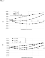
FIG. 7 is a view illustrating a result of a simulation performed to verify the winding length. -
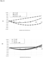
FIG. 8 is a view illustrating a result of a simulation performed to verify the winding length. -
FIG. 9 is a view illustrating a result of a simulation performed to verify the winding length. -
FIG. 10 is a view illustrating a result of a simulation performed to verify the winding length. -
FIG. 11 is a view illustrating a result of a simulation performed to verify the winding length. -
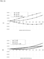
FIG. 12 is a flow chart regarding an operation of the winding apparatus. - Hereinafter, embodiments for carrying out the present invention will be described with reference to the drawings. A winding apparatus according to the present embodiment is an apparatus for forming a package used for a false-twist texturing machine.
-
FIG. 1 is a view illustrating a schematic configuration of a false-twist texturing machine 100 according to the present embodiment. The false-twist texturing machine 100 is configured to be capable of false twisting of yarns Y made of, for example, synthetic fibers such as nylon (polyamide fibers). The false-twist texturing machine 100 includes ayarn supplying unit 101, a false-twist texturing unit 102, and a windingunit 103. - The
yarn supplying unit 101 includes acreel stand 101A holding a plurality of yarn supply packages Ps. As described below, the yarn supply package Ps is formed with a cylindrical bobbin around which the yarn Y is wound. Theyarn supplying unit 101 unwinds the yarn Y from each of the plurality of yarn supply packages Ps. Theyarn supplying unit 101 supplies the unwound yarns Y to the false-twist texturing unit 102. - The false-
twist texturing unit 102 false-twists the yarns Y supplied from theyarn supplying unit 101. Specifically, the false-twist texturing unit 102 draws the yarns Y supplied from theyarn supplying unit 101 with a plurality of rollers to twist the yarns Y. The yarns Y are then cooled after being heated. Then, the false-twist texturing unit 102 thermally sets the yarns Y while being relaxed with the plurality of rollers to be supplied to the windingunit 103. - The winding
unit 103 winds a yarn Ys false-twisted by the false-twist texturing unit 102 onto a bobbin by a windingmachine 103A to form a wound package Pw. It is to be noted that, in this specification, the yarn that has already been false-twisted is referred to as the yarn Ys, and the yarn that has not yet been false-twisted is referred to as the yarn Y. - In the present embodiment, the
yarn supplying unit 101 in the false-twist texturing machine 100 unwinds the yarn Y in a shaft direction of the bobbin when unwinding the yarn Y from the yarn supply package Ps. Hereinafter, the unwinding of the yarn Y in the shaft direction of the bobbin is referred to as lateral unwinding. During the laterally unwinding, a winding state of the yarn on the yarn supply package Ps may become irregular, and/or twisting may occur, making efficient unwinding impossible. The winding apparatus of the present embodiment is an apparatus for forming the optimal yarn supply package Ps for being laterally unwound by theyarn supplying unit 101 provided in the false-twist texturing machine 100, which is an apparatus used in a pre-process of the false-twist texturing machine 100. -
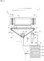
FIG. 2 is a view illustrating a schematic configuration of a windingapparatus 1 according to the present embodiment. The windingapparatus 1 is an apparatus for winding a traversed yarn Y onto a bobbin Bw to form a yarn supply package Ps. The bobbin Bw in the present embodiment is cylindrical, and at least a region on a perimeter surface of the bobbin Bw where the yarn Y is wound is cheese-shaped (more specifically, rectangular-shaped) in a planar view viewed from a direction orthogonal to a shaft direction. - In the following description, in the shaft direction of the bobbin Bw held by the winding
apparatus 1, a direction from left to right on the drawing sheet ofFIG. 2 is referred to as a first direction, and a direction opposite thereto is referred to as a second direction. Moreover, the yarn supply package Ps formed by the windingapparatus 1 is unwound from an end portion side in the second direction when being laterally unwound by the false-twist texturing machine 100. The first direction corresponds to "one direction side" of the present invention. The second direction corresponds to "the other direction side" of the present invention. - The winding
apparatus 1 includes arotating unit 10 configured to rotate the bobbin Bw centering around the shaft direction, and ayarn threading apparatus 20 configured to wind the yarn Y, which is traversed along the shaft direction of the bobbin Bw, onto the bobbin Bw. - The rotating
unit 10 includes a pair ofcradle arms 11, and acontact roller 12. The pair ofcradle arms 11 hold both of the end portions of the bobbin Bw in the shaft direction withbobbin holders 11A and make it possible to rotate the bobbin Bw viabobbin holders 11A. Although not illustrated, a hook 11B for threading the yarn Y onto the bobbin Bw is provided on thebobbin holder 11A holding an end portion of the bobbin Bw on the first direction side. - As illustrated in
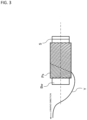
FIG. 3 , a slit S is formed along the perimeter surface at the end portion of the bobbin Bw on the first direction side.FIG. 3 is a view illustrating an unwind direction of the yarn supply package Ps. The slit S is configured so that an operator can hook the yarn Y therethrough, for example, when threading a new bobbin Bw or when accumulating the yarn Y after it has been wound several times around the bobbin Bw. Moreover, the operator connects a rear end of the yarn Y accumulated in the slit S to a front end of the yarn Y wound around the next bobbin Bw. When the yarn Y wound around the bobbin Bw is unwound, the yarn Y is unwound from an end portion on a side where the slit S is not formed. - At the beginning of winding the yarn Y, the
contact roller 12 rotates in a certain direction in contact with the perimeter surface of the bobbin Bw, thereby rotating the bobbin Bw. Moreover, in accordance with the yarn Y being wound around the bobbin Bw, thecontact roller 12 rotates in the certain direction in contact with the perimeter surface of the yarn supply package Ps, thereby rotating the yarn supply package Ps. Thecontact roller 12 is driven by a driving motor, which is not illustrated. - The
yarn threading apparatus 20 includes ayarn holding unit 21, ayarn threading arm 22, a traversingfulcrum guide 23, atraverse device 24, and acontrol device 25. - The
yarn holding unit 21 is configured to suck and hold the fed yarn Y. Theyarn threading arm 22 includes ayarn engagement portion 22A at a tip portion thereof. Theyarn engagement portion 22A holds the yarn Y which is sucked and held by theyarn holding unit 21. Theyarn threading arm 22 rotates centering around arotational shaft 22B positioned at an end portion opposite to theyarn engagement portion 22A. Theyarn threading arm 22 rotates centering around therotational shaft 22B, thereby moving theyarn engagement portion 22A closer to or farther away from the above-described hook provided on thebobbin holder 11A. Theyarn threading arm 22 threads and hooks the yarn Y onto the hook at a timing when theyarn engagement portion 22A is close to the hook. - The traversing
fulcrum guide 23 is a guide that feeds the yarn Y supplied from a device (e.g., a yarn feed roller) disposed upstream, which is not illustrated, to the bobbin Bw. Thetraverse device 24 described below is interposed between the traversingfulcrum guide 23 and the rotatingunit 10, and it is configured so that the yarn Y fed from the traversingfulcrum guide 23 is traversed by thetraverse device 24. The traversingfulcrum guide 23 is disposed at a center in a winding range of the bobbin Bw along the shaft direction (hereinafter referred to as the winding center). Moreover, the traversingfulcrum guide 23 is configured to be movable by a motor or the like, for example, on a rail extending along the shaft direction of the bobbin Bw so that a position thereof in the shaft direction of the bobbin Bw can changed. The traversingfulcrum guide 23 is moved so as to be disposed on the first direction side from the winding center, during a period from starting the winding of the yarn Y onto the bobbin Bw until a winding diameter of the yarn supply package Ps reaches a predetermined winding diameter. Specifically, during a midway process from the start of the winding of the yarn Y onto the bobbin Bw to the end of the winding, the traversingfulcrum guide 23 is moved so as to be disposed on the first direction side from the winding center. Then, when ending the winding, the traversingfulcrum guide 23 is moved so as to be disposed on the first direction side from the winding center. - The
traverse device 24 is a device that reciprocates thetraverse guide 241 which is configured to engage with the yarn Y fed out from the traversingfulcrum guide 23 and to guide the yarn Y to the bobbin Bw, along the shaft direction of the bobbin Bw, thereby traversing the yarn Y with the traversingfulcrum guide 23 as a fulcrum. Thetraverse device 24 used in the present embodiment is a type called a belt traverse. - The
traverse device 24 includes atraverse guide 241, and anendless timing belt 242 for moving thetraverse guide 241. - The
timing belt 242 is mounted over drivenpulleys pulley 33 so as to form a triangular shape. The driven pulleys 31 and 32 are disposed so as to be aligned with each other along the shaft direction of the bobbin Bw. The drivingpulley 33 is disposed on a side opposite to the rotatingunit 10 in relation to the drivenpulleys pulley 33 is rotationally driven by a traverseguide driving motor 30. Thetiming belt 242 moves as the drivingpulley 33 rotates. - The
traverse guide 241 is supported by thetiming belt 242 so as to move together with thetiming belt 242, between the drivenpulleys pulleys traverse guide 241 moves along the shaft direction of the bobbin Bw as thetiming belt 242 moves. Thetraverse guide 241 reciprocates along the shaft direction of the bobbin Bw as the moving direction of thetiming belt 242 changes. As thetraverse guide 241 reciprocates along the shaft direction of the bobbin Bw, the yarn Y fed out from the traversingfulcrum guide 23 is traversed with the traversingfulcrum guide 23 as a fulcrum. - Hereinafter, traversing the yarn Y by moving the
traverse guide 241 in the first direction is referred to as traversing in the first direction. Moreover, traversing the yarn Y by moving thetraverse guide 241 in the second direction is referred to as traversing in the second direction. - The
control device 25 is a device configured to control the windingapparatus 1 and includes a Central Processing Unit (CPU), a Read Only Memory (ROM), a Random Access Memory (RAM), and the like, and is capable of executing various controls by the CPU reading programs stored in the ROM into the RAM and executing the read programs. Thecontrol device 25 includes an obtainingunit 251, aratio changing unit 252, aposition changing unit 253, and adrive control unit 254, as functions of the CPU provided by thecontrol device 25. - The obtaining
unit 251 is configured to obtain information regarding a winding diameter of the yarn supply package Ps in the process of formation (hereinafter referred to as winding diameter information). The winding diameter of the yarn supply package Ps used herein means an outermost diameter of the yarn supply package Ps. As an obtaining method of the winding diameter information, for example, the obtainingunit 251 obtains the number of rotations of the bobbin Bw, a diameter of the bobbin Bw, a diameter of the yarn Y, and an elapsed time from the start of winding the yarn Y around the bobbin Bw, and calculates a winding diameter of the yarn supply package Ps on the basis of the obtained information. - The
ratio changing unit 252 is configured to change a ratio between a speed at which thetraverse guide 241 moves in the first direction (hereinafter referred to as a first speed) and a speed at which thetraverse guide 241 moves in the second direction (hereinafter referred to as a second speed) on the basis of the winding diameter information of the yarn supply package Ps obtained by the obtainingunit 251. In other words, theratio changing unit 252 controls the traverse of the yarn Y with the traversingfulcrum guide 23 as a fulcrum. - The
position changing unit 253 changes a position of the traversingfulcrum guide 23 in a shaft direction of the bobbin Bw to adjust an offset distance on the basis of the ratio between the first speed and the second speed of thetraverse guide 241. The offset distance used herein means a distance from the winding center to the traversing fulcrum guide 23 (distance along the moving direction of the traverse guide 241). The traversingfulcrum guide 23 is configured to be movable along the shaft direction of the bobbin Bw by a motor or the like. Theposition changing unit 253 is configured to control driving of the aforementioned motor to adjust the offset distance in accordance with the ratio between the first speed and the second speed of thetraverse guide 241. Theposition changing unit 253 allows the traversing fulcrum guide to be disposed at an optimal position even when settings of the winding speed, the winding width of the yarn supply package Ps, the moving speed of thetraverse guide 241, or the like are different or even when the winding speed, the winding width of the yarn supply package Ps, the moving speed of the traverse guide, or the like changes during the winding. - The
drive control unit 254 controls driving of a driving motor for rotating thecontact roller 12 to control the rotation of the bobbin Bw. Moreover, thedrive control unit 254 controls driving of a driving motor for rotating theyarn threading arm 22 to thread and hook the yarn Y onto the hook by means of theyarn engagement portion 22A of the yarn threading arm at an appropriate timing. - Furthermore, the
drive control unit 254 controls driving of the traverseguide driving motor 30 to rotate the drivingpulley 33, thereby moving thetraverse guide 241 in the first direction or the second direction. When the ratio between the first speed and the second speed is changed by theratio changing unit 252, thetraverse guide 241 is moved in first direction and the second direction on the basis of this ratio. In other words, in the present embodiment, thedrive control unit 254 controls not only the moving direction of thetraverse guide 241 but also the first speed of moving in the first direction and the second speed of moving in the second direction. Specifically, when the traversingfulcrum guide 23 is disposed at the winding center, thedrive control unit 254 controls the driving of the traverseguide driving motor 30 so thattraverse guide 241 moves at the same speed regardless of the moving direction of thetraverse guide 241. Moreover, when the traversingfulcrum guide 23 is disposed on the first direction side from the winding center, thedrive control unit 254 controls driving of the traverseguide driving motor 30 so that the second speed at which thetraverse guide 241 moves in the second direction is slower than the first speed at which thetraverse guide 241 moves in the first direction. By setting the first speed and the second speed to be different from each other, a traverse angle when traversing in the first direction is larger than a traverse angle when traversing in the second direction. The traverse angle used herein means an acute angle (angle Θ illustrated inFIGs. 4 and5 described below) formed between a circumferential direction of a bobbin Bw and the yarn Y wound around the bobbin Bw. When the speed of thetraverse guide 241 is changed so that the second speed is slower than the first speed, the traversingfulcrum guide 23 is disposed on the first direction side from the winding center, and thereby it is possible to form the yarn supply package Ps capable of the lateral unwinding without unfavorable unwinding occurring even when the settings of the winding speed, the winding width of the package, or the like are different, or even when the winding speed, the winding width of the package, or the like changes during the winding. - As described above, the traversing
fulcrum guide 23 is disposed at the winding center, but is disposed on the first direction side from the winding center during the midway process from the start of the winding of the yarn Y onto the bobbin Bw to the end of the winding. In other words, the traversingfulcrum guide 23 is disposed on the one direction side from the winding center when reciprocating the yarn so that the second speed at which thetraverse guide 241 moves in the second direction is slower than the first speed at which thetraverse guide 241 moves in the first direction. As described below, even when the first speed and the second speed are different from each other, lengths of the yarn Y wound around the bobbin Bw (hereinafter referred to as winding lengths) are the same between the case of traversing in the first direction and the case of traversing in the second direction. Consequently, winding tensions of the yarn Y are the same between the case of traversing in the first direction and the case of traversing in the second direction, so that a high-quality yarn supply package Ps is formed. - Below are shown results of a simulation performed to verify that the winding lengths of the yarn Y are the same between the case of traversing in the first direction and the case of traversing in the second direction by adopting the above-described configuration into the winding
apparatus 1. -
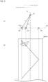
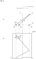
FIGs. 4 and5 are views for describing parameters of the simulation performed to verify the winding lengths.FIG. 4 is the view illustrating a case where the traversingfulcrum guide 23 is disposed at the winding center.FIG. 5 is the view illustrating a case where the traversingfulcrum guide 23 is disposed on the first direction side from the winding center. (A) of each ofFIGs. 4 and5 is the view illustrating the length of the yarn Y from the traversingfulcrum guide 23 to thetraverse guide 241. (B) of each ofFIGs. 4 and5 is the view illustrating a perimeter surface of the bobbin Bw (or the yarn supply package Ps) in a planar view, which illustrates the length of the yarn Y wound around the perimeter surface. In each ofFIGs. 4 and5 , the dash-dot line P1 is a line passing through the winding center and orthogonal to the shaft direction of the bobbin Bw. The dashed line P2 is a line passing through a moving track of thetraverse guide 241. Thetraverse guide 241 shall move between the position A and the position C on the dashed line P2. - When the yarn Y is traversed, the length of the yarn Y from the traversing
fulcrum guide 23 to the traverse guide 241 (hereinafter referred to as a guide length) changes as thetraverse guide 241 moves. In (A) of each ofFIGs. 4 and5 , L1 represents the guide length when thetraverse guide 241 is positioned at the position A. L2 represents the guide length when thetraverse guide 241 moves from the position A in the first direction and is positioned at the position B. In this case, the difference Ld1 in the guide length between the position A and the position B can be expressed as L1-L2. In addition, the angle Θ illustrated in (B) of each ofFIGs. 4 and5 is the above-described traverse angle formed between the circumferential direction of the bobbin Bw and the yarn Y wound around the bobbin Bw. - Moreover, when the winding times of the yarn Y are the same in the case where the yarn Y is traversed and in the case of not being traversed, the lengths of the yarn Y wound around the bobbin Bw (or around the yarn supply package Ps) (hereinafter referred to as a wound length) are different from each other in both the cases. In (B) of each of
FIGs. 4 and5 , L3 represents the wound length when the yarn Y is wound around the bobbin Bw at the position A without traverse of the yarn Y. Moreover, L4 represents the wound length when thetraverse guide 241 is moved from the position A to the position B. In this case, the difference Ld2 in the wound length between the case where the yarn Y is traversed and the case of not being traversed can be expressed as L4-L3. - A simulation is performed to verify the winding lengths by detecting the above-mentioned difference Ld1 in the guide length and the above-mentioned difference Ld2 in the winding length at predetermined intervals in the case where the
traverse guide 241 is moved from the position A to the position C and the case of being moved from the position C to the position A. Below are shown results thereof.FIGs. 6 ,7 ,8 ,9 ,10 , and11 are views illustrating results of the simulation performed to verify the winding lengths.FIG. 6 illustrates the result of the simulation when the traversingfulcrum guide 23 is disposed at the winding center.FIGs. 7 to 11 illustrate the results of the simulation when the traversingfulcrum guide 23 is disposed on the first direction side from the winding center. - In each of
FIGs. 6 to 11 , the horizontal axis represents a winding width position and the vertical axis represents the length of the yarn. Moreover, in each ofFIGs. 6 to 11, (A) illustrates the results when traversing in the first direction, and (B) illustrates the result when traversing in the second direction. In each ofFIGs. 6 to 11 , the graph line (1) indicates the detected difference Ld2 in the wound length, the graph line (2) indicates the detected difference Ld1 in the guide length, and the graph line (3) indicates a total value of the difference Ld2 in the wound length and the difference Ld1 in the guide length. The winding width position used herein means a length from a position of starting the winding to a position of thetraverse guide 241 which has moved in the first direction or the second direction. For example, when the winding is started from the position A and thetraverse guide 241 moves to the position B along the first direction, the length from the position A to the position B corresponds to the winding width position. When the winding is started from the position C and thetraverse guide 241 moves to the position B along the second direction, the length from the position C to the position B corresponds to the winding width position. - In the simulation in
FIG. 6 , the winding width is 120 mm, a traversing fulcrum distance (distance from the dashed line P2 to the traversingfulcrum guide 23 inFIGs. 4 and5 (distance in the up-and-down direction of the drawing sheet inFIGs. 4 and5 , and the same applies below)) is 500 mm, the rotation speed of the bobbin Bw is 1000 m/min, and the speed of thetraverse guide 241 is 105.1 m/min (traverse angle is 6 degrees). - In the simulation in
FIG. 7 , the winding width is 120 mm, an offset distance (distance from the dash-dot line P1 to the traversingfulcrum guide 23 inFIG. 5 (distance in the right-left direction of the drawing sheet inFIG. 5 , and the same applies below)) of the traversingfulcrum guide 23 is 9.5 mm, the traversing fulcrum distance (distance from the dashed line P2 to the traversingfulcrum guide 23 inFIGs. 4 and5 ) is 500 mm, the rotation speed of the bobbin Bw is 1000 m/min, the first speed of thetraverse guide 241 is 140.5 m/min (traverse angle is 8 degrees), and the second speed of thetraverse guide 241 is 69.9 m/min (traverse angle is 4 degrees). - In the simulation in
FIG. 8 , the winding width is 120 mm, the offset distance of the traversingfulcrum guide 23 is 14.5 mm, the traversing fulcrum distance is 500 mm, the rotation speed of the bobbin Bw is 1000 m/min, the first speed of thetraverse guide 241 is 148.4 m/min (traverse angle is 9 degrees), and the second speed of thetraverse guide 241 is 52.4 m/min (traverse angle is 3 degrees). - In the simulation in
FIG. 9 , the winding width is 120 mm, the offset distance of the traversingfulcrum guide 23 is 11 mm, the traversing fulcrum distance is 500 mm, the rotation speed of the bobbin Bw is 1000 m/min, the first speed of thetraverse guide 241 is 105.1 m/min (traverse angle is 6 degrees), and the second speed of thetraverse guide 241 is 17.5 m/min (traverse angle is 1 degree). - In the simulation in
FIG. 10 , the winding width is 200 mm, the offset distance of the traversingfulcrum guide 23 is 27 mm, the traversing fulcrum distance is 800 mm, the rotation speed of the bobbin Bw is 1000 m/min, the first speed of thetraverse guide 241 is 286.7 m/min (traverse angle is 16 degrees), and the second speed of thetraverse guide 241 is 140.5 m/min (traverse angle is 8 degrees). - In the simulation in
FIG. 11 , the winding width is 200 mm, the offset distance of the traversingfulcrum guide 23 is 43 mm, the traversing fulcrum distance is 800 mm, the rotation speed of the bobbin Bw is 1000 m/min, the first speed of thetraverse guide 241 is 324.9 m/min (traverse angle is 18 degrees), and the second speed of thetraverse guide 241 is 105.1 m/min (traverse angle is 6 degrees). - In the case of
FIG. 6 , the difference Ld1 in the guide length when traversing in the first direction is the same as the difference Ld1 in the guide length when traversing in the second direction, and the difference Ld2 in the guide length when traversing in the first direction is the same as the difference Ld2 in the guide length when traversing in the second direction. Therefore, the winding lengths of the yarn Y are the same between the case of traversing in the first direction and the case of traversing in the second direction. Accordingly, since the yarn Y is always wound around the bobbin Bw at a constant winding tension, it is possible to form a high-quality yarn supply package Ps. - In each of the cases in
FIGs. 7 to 11 , the difference Ld1 in the guide length when traversing in the first direction is different from the difference Ld1 in the guide length when traversing in the second direction, and the difference Ld2 in the guide length when traversing in the first direction is different from the difference Ld2 in the guide length when traversing in the second direction. On the other hand, the total value of the difference Ld2 in the wound length and the difference Ld1 in the guide length is the same between the case of traversing in the first direction and the case of traversing in the second direction. Therefore, the winding lengths of the yarn Y are the same between the case of traversing in the first direction and the case of traversing in the second direction. Accordingly, since the yarn Y is always wound around the bobbin Bw at a constant winding tension, it is possible to form a high-quality yarn supply package Ps. -
FIG. 12 is a flow chart regarding an operation of the windingapparatus 1. The windingapparatus 1 executes a process in the flow chart illustrated inFIG. 12 by the CPU of thecontrol device 25 reading a program stored in the ROM into the RAM to be executed. Moreover, in the present embodiment, a winding method is executed by operating the windingapparatus 1. Accordingly, the description of the winding method in the present embodiment is substituted by the following description of the operation of the windingapparatus 1. At the time of starting of the operation illustrated inFIG. 12 , the traversingfulcrum guide 23 is disposed at the winding center. - When the bobbin Bw is held by the pair of
cradle arms 11, thecontrol device 25 causes theyarn engagement portion 22A to hold the yarn Y, and rotates theyarn threading arm 22 to thread and hook the yarn Y onto the hook (S1). Next, thecontrol device 25 moves the traversingfulcrum guide 23 from the winding center to the first direction side (S2). Then, thecontrol device 25 rotates thecontact roller 12, thereby rotating the bobbin Bw (S3). Consequently, the winding of the yarn Y onto the bobbin Bw is started. - The
control device 25 controls driving of the traverseguide driving motor 30 to rotate the drivingpulley 33, thereby controlling movement of the traverse guide 241 (S4). At this time, thecontrol device 25 moves thetraverse guide 241 in the first direction at the first speed, and moves thetraverse guide 241 in the second direction at the second speed (< the first speed). Thecontrol device 25 obtains information on the winding diameter of the yarn supply package Ps (S5). Thecontrol device 25 determines whether the winding diameter is equal to or greater than a threshold value on the basis of the obtained information on the winding diameter (S6). If the winding diameter is not equal to or greater than the threshold value (S6: NO), thecontrol device 25 changes the first speed and the second speed (S7) in accordance with the obtained information on the winding diameter to adjust the offset distance of the traversing fulcrum guide 23 (S8). Then, thecontrol device 25 executes the process of S5 again. - If the winding diameter is equal to or greater than the threshold value in the process of S6 (S6: YES), the
control device 25 moves the traversingfulcrum guide 23 to the winding center (S9), performs speed control to make the speed of thetraverse guide 241 the same between the first direction and the second direction (S10), and moves thetraverse guide 241. Then, thecontrol device 25 waits until the winding is completed (S11), and when the winding is completed, ends the process illustrated inFIG. 12 . - The winding
apparatus 1 configured as described above can form a yarn supply package Ps capable of efficient unwinding when the laterally unwinding from the end portion of the bobbin Bw in the second direction. When performing laterally unwinding from the yarn supply package, which is formed by winding the yarn Y onto the bobbin Bw by using a conventional winding apparatus, the yarn to be unwound and the yarn wound around the bobbin Bw may be caught due to friction therebetween, and therefore efficient unwinding may not be performed. In particular, when unwinding in the second direction, the yarn wound from the end portion of the bobbin Bw in the first direction toward the end portion in the second direction cannot be efficiently unwound. Therefore, in the present embodiment, when traversing in the first direction, the traverse angle is increased, and when traversing in the second direction, the traverse angle is decreased. This makes it possible to suppress the yarns from getting caught on each other when unwinding in the second direction, thereby enabling efficient unwinding. - Moreover, in the present embodiment, in principle, the traversing
fulcrum guide 23 is disposed at the winding center, and the first speed and the second speed of thetraverse guide 241 are made the same. However, during the midway process from the start of the winding of the yarn Y onto the bobbin Bw to the end of the winding, thetraverse guide 241 is reciprocated so that the second speed is slower than the first speed, and the position of the traversingfulcrum guide 23 is disposed to be offset toward the first direction side from the winding center within a winding range of the bobbin Bw. Consequently, even when the first speed is different from the second speed, it is possible to make the winding length of the yarn Y the same between the case of traversing in the first direction and the case of traversing in the second direction. Since the rotation speed of the bobbin Bw is constant, the winding tensions of the yarn Y are the same between the case of traversing in the first direction and the case of traversing in the second direction. If the winding tensions are different between the case of traversing in the first direction and the case of traversing in the second direction, there is a risk of degradation of the yarn supply package Ps, a yarn break occurring midway, or the like. Accordingly, the yarn Y is wound around the bobbin Bw at a constant winding tension, thereby making it possible to form a high-quality yarn supply package Ps. - Moreover, in the present embodiment, when the winding diameter of the yarn supply package Ps becomes equal to or greater than the threshold value, the traversing
fulcrum guide 23 is moved to the winding center as in principle, and the first speed and the second speed of thetraverse guide 241 are always the same constant speed. For example, when the yarn Y is wound onto the yarn supply package Ps with a large curvature in a state where the traversingfulcrum guide 23 is offset from the winding center, the traverse angle at the end portion on the offset side (first direction side) of the yarn supply package Ps becomes large. In this case, when laterally unwinding in the unwind direction (refer toFIG. 3 ), friction of the yarn Y occurs. Therefore, when the yarn Y is wound onto the yarn supply package Ps with a large curvature, the traverse angle can be reduced by disposing the position of the traversingfulcrum guide 23 at the winding center. Consequently, it is possible to prevent friction of the yarn Y and to form a high-quality yarn supply package Ps. - However, during the entire process from the start of the winding of the yarn Y onto the bobbin Bw to the end of the winding, the
traverse guide 241 may be reciprocated so that the second speed is slower than the first speed, and the position of the traversingfulcrum guide 23 may be disposed to be offset toward the first direction side from the winding center within the winding range of the bobbin Bw. For example, it is effective in particular when the winding diameter of the yarn supply package at the time when the end of the winding is smaller than the above-described threshold value. - Furthermore, in the present embodiment, it is possible to change the traverse angle by changing the position of the traversing
fulcrum guide 23. This not only makes it possible to make the winding length of the yarn Y the same between the case of traversing in the first direction and the case of traversing in the second direction, but also makes it possible to wind the yarn Y at an optimal traverse angle, thereby forming a yarn supply package Ps with excellent lateral unwinding properties. - While the embodiments of the present invention have been described above, the present invention is not limited to the above-described embodiments but can be changed in various ways within a scope recited in the claims. For example, the winding
apparatus 1 of the above-described embodiment is configured so that thetraverse guide 241 reciprocates controlled by thecontrol device 25, using the belt traverse as a traverse device. However, instead of the belt traverse, a blade traverse, a drum traverse, a cam traverse, or an arm traverse may be used to change the ratio between the first speed and the second speed of thetraverse guide 241. - Moreover, in the above embodiment, the
control device 25 is configured to have the functions of each part by executing an installed program, but it may also be implemented by using hardware corresponding to each part. Alternatively, a part of thecontrol device 25 may be implemented by a program and the rest thereof may be implemented by hardware. Furthermore, each process executed by thecontrol device 25 may not be executed in the order described withFIG. 12 , but the order may be changed as appropriate. - In the above-described embodiment, the obtaining
unit 251 has been described as being configured to calculate the winding diameter information from various pieces of information. However, the obtainingunit 251 may be configured to irradiate the yarn supply package Ps with ultrasonic waves or laser light to detect the winding diameter of the yarn supply package Ps from reflected light. Alternatively, the obtainingunit 251 may be configured to capture an image of the yarn supply package Ps with an image capture device to detect the winding diameter of the yarn supply package Ps through image processing. Alternatively, the obtainingunit 251 may be configured to obtain the winding diameter of the yarn supply package Ps detected by another external device from this external device, or may be configured to obtain the winding diameter which is manually entered. -
- 1
- Winding apparatus
- 10
- Rotating unit
- 11
- Cradle arm
- 11A
- Bobbin holder
- 12
- Contact roller
- 20
- Yarn threading apparatus
- 21
- Yarn holding unit
- 22
- Yarn threading arm
- 23
- Traversing fulcrum guide
- 24
- Traverse device
- 25
- Control device
- 30
- Traverse guide driving motor
- 31, 32
- Driven pulley
- 241
- Traverse guide
- 242
- Timing belt
- 251
- Obtaining unit
- 252
- Ratio changing unit
- 253
- Position changing unit
- 254
- Drive control unit
- Bw
- Bobbin
- Ps
- Yarn supply package
- Y
- Yarn
Claims (8)
- A winding apparatus (1) configured to wind a yarn (Y) traversed in a shaft direction of a cylindrical bobbin (Bw) onto the bobbin (Bw) to form a package (Ps), the winding apparatus (1) comprising:a rotating unit (10) configured to rotate the bobbin centering around a shaft of the bobbin (Bw);a traversing fulcrum guide (23); anda traverse device (24) configured to reciprocate the yarn (Y) fed out from the traversing fulcrum guide (23) and guided to the bobbin (Bw) between one direction side and another direction side of a traverse direction along the shaft direction and to traverse the yarn (Y) with the traversing fulcrum guide (23) as a fulcrum, whereinthe traverse device (24) reciprocates the yarn (Y) so that a speed to the other direction side is slower than a speed to the one direction side during a midway process or an entire process from a start of the winding of the yarn (Y) onto the bobbin (Bw) to an end of the winding thereof, andwhen the yarn (Y) reciprocated by the traverse device (24) so that the speed to the other direction side is slower than the speed to the one direction side, the traversing fulcrum guide (23) is disposed on the one direction side along the shaft direction from a center in the winding range of the bobbin (Bw).
- The winding apparatus (1) as claimed in claim 1, wherein
the traverse device (24) reciprocates the yarn (Y) so as to be parallel to the shaft direction of the bobbin (Bw) when reciprocating the yarn (Y). - The winding apparatus (1) as claimed in claim 1 or 2, whereinthe traversing fulcrum guide (23) is disposed at a center in a winding range of the bobbin (Bw) along the shaft direction, andwhen the yarn (Y) is reciprocated by the traverse device (24) so that the speed to the other direction side is slower than the speed to the one direction side, the traversing fulcrum guide (23) is disposed on the one direction side along the shaft direction from a center in the winding range of the bobbin (Bw).
- The winding apparatus (1) as claimed in claim 1 or 2, whereinthe traverse device (24) includes a traverse guide (241) configured to engage with the yarn (Y) fed out from the traversing fulcrum guide (23) and guided to the bobbin (Bw), and to be capable of reciprocating between the one direction side and the other direction side of the traverse direction, andthe winding apparatus further comprises a ratio changing unit (252) configured to reciprocate the traverse guide (241) and to be capable of changing of a ratio of moving speeds of the traverse guide (241) between the one direction side and the other direction side of the traverse direction.
- The winding apparatus (1) as claimed in claim 4, further comprisingan obtaining unit (251) configured to obtain information regarding a winding diameter of the package (Ps) in a process of formation, whereinthe ratio changing unit (252) is capable of changing the ratio of the moving speeds of the traverse guide (241) in accordance with the information obtained by the obtaining unit (251).
- The winding apparatus (1) as claimed in any one of claims 1-5, further comprising
a position changing unit (253) configured to change a position of the traversing fulcrum guide (23) in the shaft direction. - The winding apparatus (1) as claimed in claim 4 or 5, further comprisinga position changing unit (253) configured to change a position of the traversing fulcrum guide (23) in the shaft direction, whereinthe position changing unit (253) changes the position of the traversing fulcrum guide (23) in the shaft direction on the basis of the ratio of the moving speeds of the traverse guide (241).
- The winding apparatus (1) as claimed in any one of claims 1-7, wherein
the midway process from the start of the winding of the yarn (Y) onto the bobbin (Bw) to the end of the winding thereof is a period from the start of winding of the yarn (Y) onto the bobbin (Bw) to a time point when a winding diameter of the package reaches a predetermined winding diameter.
Applications Claiming Priority (1)
| Application Number | Priority Date | Filing Date | Title |
|---|---|---|---|
| JP2023223148 | 2023-12-28 |
Publications (2)
| Publication Number | Publication Date |
|---|---|
| EP4582364A1 true EP4582364A1 (en) | 2025-07-09 |
| EP4582364B1 EP4582364B1 (en) | 2025-12-03 |
Family
ID=93923977
Family Applications (1)
| Application Number | Title | Priority Date | Filing Date |
|---|---|---|---|
| EP24219921.4A Active EP4582364B1 (en) | 2023-12-28 | 2024-12-13 | Winding apparatus |
Country Status (4)
| Country | Link |
|---|---|
| EP (1) | EP4582364B1 (en) |
| JP (1) | JP2025105504A (en) |
| CN (1) | CN120229609A (en) |
| TW (1) | TW202525691A (en) |
Citations (2)
| Publication number | Priority date | Publication date | Assignee | Title |
|---|---|---|---|---|
| EP0999992B1 (en) * | 1997-07-26 | 2004-01-28 | Barmag Ag | Process and cross-winding device for laying a thread |
| JP2004142944A (en) | 2002-09-30 | 2004-05-20 | Fuji Spinning Co Ltd | Elastic wound body and manufacturing method thereof |
-
2024
- 2024-12-02 CN CN202411748369.0A patent/CN120229609A/en active Pending
- 2024-12-10 JP JP2024215243A patent/JP2025105504A/en active Pending
- 2024-12-11 TW TW113148001A patent/TW202525691A/en unknown
- 2024-12-13 EP EP24219921.4A patent/EP4582364B1/en active Active
Patent Citations (2)
| Publication number | Priority date | Publication date | Assignee | Title |
|---|---|---|---|---|
| EP0999992B1 (en) * | 1997-07-26 | 2004-01-28 | Barmag Ag | Process and cross-winding device for laying a thread |
| JP2004142944A (en) | 2002-09-30 | 2004-05-20 | Fuji Spinning Co Ltd | Elastic wound body and manufacturing method thereof |
Also Published As
| Publication number | Publication date |
|---|---|
| JP2025105504A (en) | 2025-07-10 |
| EP4582364B1 (en) | 2025-12-03 |
| TW202525691A (en) | 2025-07-01 |
| CN120229609A (en) | 2025-07-01 |
Similar Documents
| Publication | Publication Date | Title |
|---|---|---|
| US10676311B2 (en) | Method of manufacturing and manufacturing device for partial split-fiber fiber bundle and partial split-fiber fiber bundle | |
| EP2407407B1 (en) | Yarn threading method of take-up winding apparatus and take-up winding apparatus | |
| CN104220657A (en) | Methods and systems for regulating tension in warping | |
| KR101329109B1 (en) | Yarn winding device, take-up winder using the yarn winding device, yarn winding method, take-up winding method using the yarn winding method, and taper end package | |
| EP2366649A2 (en) | Yarn winding machine | |
| EP4242152B1 (en) | Yarn threading apparatus, false-twist texturing machine, and yarn threading method | |
| EP4582364B1 (en) | Winding apparatus | |
| EP2636624A2 (en) | Take-up apparatus | |
| JP5368205B2 (en) | Control device for traverse device | |
| CN1273934A (en) | Winding method of one continuously feeding yarn | |
| JP6027344B2 (en) | Textile machinery | |
| TWI799643B (en) | Yarn winding machine and method for producing packages | |
| EP2937303B1 (en) | Winding drum, winding device and yarn winding machine | |
| CN1031933C (en) | Winding machine | |
| JP2013154991A (en) | Yarn winding machine and yarn winding method | |
| JPS6245149B2 (en) | ||
| EP2910507A1 (en) | Yarn accumulating device, yarn winding unit including the same, and yarn winding machine including the same | |
| CN1268532C (en) | Method of winding monofilament | |
| JP2007238245A (en) | Yarn winder | |
| JP2008024438A (en) | Yarn winding device | |
| JP2003192230A (en) | Support roller | |
| EP4382467A1 (en) | Yarn threading apparatus and false-twist texturing machine | |
| JP2025149112A (en) | Thread winding device | |
| CN120698304A (en) | Wire winding device | |
| JP2867961B2 (en) | Braid winding device |
Legal Events
| Date | Code | Title | Description |
|---|---|---|---|
| PUAI | Public reference made under article 153(3) epc to a published international application that has entered the european phase |
Free format text: ORIGINAL CODE: 0009012 |
|
| STAA | Information on the status of an ep patent application or granted ep patent |
Free format text: STATUS: THE APPLICATION HAS BEEN PUBLISHED |
|
| AK | Designated contracting states |
Kind code of ref document: A1 Designated state(s): AL AT BE BG CH CY CZ DE DK EE ES FI FR GB GR HR HU IE IS IT LI LT LU LV MC ME MK MT NL NO PL PT RO RS SE SI SK SM TR |
|
| STAA | Information on the status of an ep patent application or granted ep patent |
Free format text: STATUS: REQUEST FOR EXAMINATION WAS MADE |
|
| GRAP | Despatch of communication of intention to grant a patent |
Free format text: ORIGINAL CODE: EPIDOSNIGR1 |
|
| STAA | Information on the status of an ep patent application or granted ep patent |
Free format text: STATUS: GRANT OF PATENT IS INTENDED |
|
| 17P | Request for examination filed |
Effective date: 20250804 |
|
| RIC1 | Information provided on ipc code assigned before grant |
Ipc: B65H 59/10 20060101AFI20250806BHEP Ipc: B65H 59/38 20060101ALI20250806BHEP Ipc: B65H 54/28 20060101ALI20250806BHEP Ipc: B65H 57/06 20060101ALI20250806BHEP |
|
| INTG | Intention to grant announced |
Effective date: 20250819 |
|
| GRAS | Grant fee paid |
Free format text: ORIGINAL CODE: EPIDOSNIGR3 |
|
| GRAA | (expected) grant |
Free format text: ORIGINAL CODE: 0009210 |
|
| STAA | Information on the status of an ep patent application or granted ep patent |
Free format text: STATUS: THE PATENT HAS BEEN GRANTED |
|
| P01 | Opt-out of the competence of the unified patent court (upc) registered |
Free format text: CASE NUMBER: UPC_APP_0010685_4582364/2025 Effective date: 20251022 |
|
| AK | Designated contracting states |
Kind code of ref document: B1 Designated state(s): AL AT BE BG CH CY CZ DE DK EE ES FI FR GB GR HR HU IE IS IT LI LT LU LV MC ME MK MT NL NO PL PT RO RS SE SI SK SM TR |
|
| REG | Reference to a national code |
Ref country code: CH Ref legal event code: F10 Free format text: ST27 STATUS EVENT CODE: U-0-0-F10-F00 (AS PROVIDED BY THE NATIONAL OFFICE) Effective date: 20251203 Ref country code: GB Ref legal event code: FG4D |
|
| REG | Reference to a national code |
Ref country code: DE Ref legal event code: R096 Ref document number: 602024001530 Country of ref document: DE |
|
| REG | Reference to a national code |
Ref country code: IE Ref legal event code: FG4D |
|
| REG | Reference to a national code |
Ref country code: CH Ref legal event code: R17 Free format text: ST27 STATUS EVENT CODE: U-0-0-R10-R17 (AS PROVIDED BY THE NATIONAL OFFICE) Effective date: 20260210 |
|
| REG | Reference to a national code |
Ref country code: NL Ref legal event code: MP Effective date: 20251203 |
|
| PG25 | Lapsed in a contracting state [announced via postgrant information from national office to epo] |
Ref country code: ES Free format text: LAPSE BECAUSE OF FAILURE TO SUBMIT A TRANSLATION OF THE DESCRIPTION OR TO PAY THE FEE WITHIN THE PRESCRIBED TIME-LIMIT Effective date: 20251203 |
|
| REG | Reference to a national code |
Ref country code: LT Ref legal event code: MG9D |
|
| PG25 | Lapsed in a contracting state [announced via postgrant information from national office to epo] |
Ref country code: NO Free format text: LAPSE BECAUSE OF FAILURE TO SUBMIT A TRANSLATION OF THE DESCRIPTION OR TO PAY THE FEE WITHIN THE PRESCRIBED TIME-LIMIT Effective date: 20260303 |
|
| PG25 | Lapsed in a contracting state [announced via postgrant information from national office to epo] |
Ref country code: HR Free format text: LAPSE BECAUSE OF FAILURE TO SUBMIT A TRANSLATION OF THE DESCRIPTION OR TO PAY THE FEE WITHIN THE PRESCRIBED TIME-LIMIT Effective date: 20251203 Ref country code: FI Free format text: LAPSE BECAUSE OF FAILURE TO SUBMIT A TRANSLATION OF THE DESCRIPTION OR TO PAY THE FEE WITHIN THE PRESCRIBED TIME-LIMIT Effective date: 20251203 |
|
| PG25 | Lapsed in a contracting state [announced via postgrant information from national office to epo] |
Ref country code: RS Free format text: LAPSE BECAUSE OF FAILURE TO SUBMIT A TRANSLATION OF THE DESCRIPTION OR TO PAY THE FEE WITHIN THE PRESCRIBED TIME-LIMIT Effective date: 20260303 |
|
| PG25 | Lapsed in a contracting state [announced via postgrant information from national office to epo] |
Ref country code: PL Free format text: LAPSE BECAUSE OF FAILURE TO SUBMIT A TRANSLATION OF THE DESCRIPTION OR TO PAY THE FEE WITHIN THE PRESCRIBED TIME-LIMIT Effective date: 20251203 |
|
| PG25 | Lapsed in a contracting state [announced via postgrant information from national office to epo] |
Ref country code: LV Free format text: LAPSE BECAUSE OF FAILURE TO SUBMIT A TRANSLATION OF THE DESCRIPTION OR TO PAY THE FEE WITHIN THE PRESCRIBED TIME-LIMIT Effective date: 20251203 |
|
| PG25 | Lapsed in a contracting state [announced via postgrant information from national office to epo] |
Ref country code: BG Free format text: LAPSE BECAUSE OF FAILURE TO SUBMIT A TRANSLATION OF THE DESCRIPTION OR TO PAY THE FEE WITHIN THE PRESCRIBED TIME-LIMIT Effective date: 20251203 |
|
| REG | Reference to a national code |
Ref country code: AT Ref legal event code: MK05 Ref document number: 1863448 Country of ref document: AT Kind code of ref document: T Effective date: 20251203 |
|
| PG25 | Lapsed in a contracting state [announced via postgrant information from national office to epo] |
Ref country code: NL Free format text: LAPSE BECAUSE OF FAILURE TO SUBMIT A TRANSLATION OF THE DESCRIPTION OR TO PAY THE FEE WITHIN THE PRESCRIBED TIME-LIMIT Effective date: 20251203 |
|
| PG25 | Lapsed in a contracting state [announced via postgrant information from national office to epo] |
Ref country code: LT Free format text: LAPSE BECAUSE OF FAILURE TO SUBMIT A TRANSLATION OF THE DESCRIPTION OR TO PAY THE FEE WITHIN THE PRESCRIBED TIME-LIMIT Effective date: 20251203 |
|
| PG25 | Lapsed in a contracting state [announced via postgrant information from national office to epo] |
Ref country code: SM Free format text: LAPSE BECAUSE OF FAILURE TO SUBMIT A TRANSLATION OF THE DESCRIPTION OR TO PAY THE FEE WITHIN THE PRESCRIBED TIME-LIMIT Effective date: 20251203 |
|
| PG25 | Lapsed in a contracting state [announced via postgrant information from national office to epo] |
Ref country code: AT Free format text: LAPSE BECAUSE OF FAILURE TO SUBMIT A TRANSLATION OF THE DESCRIPTION OR TO PAY THE FEE WITHIN THE PRESCRIBED TIME-LIMIT Effective date: 20251203 |
|
| PG25 | Lapsed in a contracting state [announced via postgrant information from national office to epo] |
Ref country code: EE Free format text: LAPSE BECAUSE OF FAILURE TO SUBMIT A TRANSLATION OF THE DESCRIPTION OR TO PAY THE FEE WITHIN THE PRESCRIBED TIME-LIMIT Effective date: 20251203 |
|
| PG25 | Lapsed in a contracting state [announced via postgrant information from national office to epo] |
Ref country code: IS Free format text: LAPSE BECAUSE OF FAILURE TO SUBMIT A TRANSLATION OF THE DESCRIPTION OR TO PAY THE FEE WITHIN THE PRESCRIBED TIME-LIMIT Effective date: 20260403 Ref country code: PT Free format text: LAPSE BECAUSE OF FAILURE TO SUBMIT A TRANSLATION OF THE DESCRIPTION OR TO PAY THE FEE WITHIN THE PRESCRIBED TIME-LIMIT Effective date: 20260406 |
|
| PG25 | Lapsed in a contracting state [announced via postgrant information from national office to epo] |
Ref country code: CZ Free format text: LAPSE BECAUSE OF FAILURE TO SUBMIT A TRANSLATION OF THE DESCRIPTION OR TO PAY THE FEE WITHIN THE PRESCRIBED TIME-LIMIT Effective date: 20251203 |
|
| PG25 | Lapsed in a contracting state [announced via postgrant information from national office to epo] |
Ref country code: SK Free format text: LAPSE BECAUSE OF FAILURE TO SUBMIT A TRANSLATION OF THE DESCRIPTION OR TO PAY THE FEE WITHIN THE PRESCRIBED TIME-LIMIT Effective date: 20251203 |
|
| PG25 | Lapsed in a contracting state [announced via postgrant information from national office to epo] |
Ref country code: SE Free format text: LAPSE BECAUSE OF FAILURE TO SUBMIT A TRANSLATION OF THE DESCRIPTION OR TO PAY THE FEE WITHIN THE PRESCRIBED TIME-LIMIT Effective date: 20251203 |