EP4582299A1 - Charger control method and apparatus, charger, and vehicle - Google Patents
Charger control method and apparatus, charger, and vehicle Download PDFInfo
- Publication number
- EP4582299A1 EP4582299A1 EP23858972.5A EP23858972A EP4582299A1 EP 4582299 A1 EP4582299 A1 EP 4582299A1 EP 23858972 A EP23858972 A EP 23858972A EP 4582299 A1 EP4582299 A1 EP 4582299A1
- Authority
- EP
- European Patent Office
- Prior art keywords
- bridge arm
- charger
- current
- voltage
- phase bridge
- Prior art date
- Legal status (The legal status is an assumption and is not a legal conclusion. Google has not performed a legal analysis and makes no representation as to the accuracy of the status listed.)
- Pending
Links
Images

Classifications
-
- H—ELECTRICITY
- H02—GENERATION; CONVERSION OR DISTRIBUTION OF ELECTRIC POWER
- H02M—APPARATUS FOR CONVERSION BETWEEN AC AND AC, BETWEEN AC AND DC, OR BETWEEN DC AND DC, AND FOR USE WITH MAINS OR SIMILAR POWER SUPPLY SYSTEMS; CONVERSION OF DC OR AC INPUT POWER INTO SURGE OUTPUT POWER; CONTROL OR REGULATION THEREOF
- H02M3/00—Conversion of DC power input into DC power output
- H02M3/22—Conversion of DC power input into DC power output with intermediate conversion into AC
- H02M3/24—Conversion of DC power input into DC power output with intermediate conversion into AC by static converters
- H02M3/28—Conversion of DC power input into DC power output with intermediate conversion into AC by static converters using discharge tubes with control electrode or semiconductor devices with control electrode to produce the intermediate AC
- H02M3/325—Conversion of DC power input into DC power output with intermediate conversion into AC by static converters using discharge tubes with control electrode or semiconductor devices with control electrode to produce the intermediate AC using devices of a triode or a transistor type requiring continuous application of a control signal
- H02M3/335—Conversion of DC power input into DC power output with intermediate conversion into AC by static converters using discharge tubes with control electrode or semiconductor devices with control electrode to produce the intermediate AC using devices of a triode or a transistor type requiring continuous application of a control signal using semiconductor devices only
- H02M3/3353—Conversion of DC power input into DC power output with intermediate conversion into AC by static converters using discharge tubes with control electrode or semiconductor devices with control electrode to produce the intermediate AC using devices of a triode or a transistor type requiring continuous application of a control signal using semiconductor devices only having at least two simultaneously operating switches on the input side, e.g. "double forward" or "double (switched) flyback" converter
-
- B—PERFORMING OPERATIONS; TRANSPORTING
- B60—VEHICLES IN GENERAL
- B60L—PROPULSION OF ELECTRICALLY-PROPELLED VEHICLES; SUPPLYING ELECTRIC POWER FOR AUXILIARY EQUIPMENT OF ELECTRICALLY-PROPELLED VEHICLES; ELECTRODYNAMIC BRAKE SYSTEMS FOR VEHICLES IN GENERAL; MAGNETIC SUSPENSION OR LEVITATION FOR VEHICLES; MONITORING OPERATING VARIABLES OF ELECTRICALLY-PROPELLED VEHICLES; ELECTRIC SAFETY DEVICES FOR ELECTRICALLY-PROPELLED VEHICLES
- B60L53/00—Methods of charging batteries, specially adapted for electric vehicles; Charging stations or on-board charging equipment therefor; Exchange of energy storage elements in electric vehicles
-
- B—PERFORMING OPERATIONS; TRANSPORTING
- B60—VEHICLES IN GENERAL
- B60L—PROPULSION OF ELECTRICALLY-PROPELLED VEHICLES; SUPPLYING ELECTRIC POWER FOR AUXILIARY EQUIPMENT OF ELECTRICALLY-PROPELLED VEHICLES; ELECTRODYNAMIC BRAKE SYSTEMS FOR VEHICLES IN GENERAL; MAGNETIC SUSPENSION OR LEVITATION FOR VEHICLES; MONITORING OPERATING VARIABLES OF ELECTRICALLY-PROPELLED VEHICLES; ELECTRIC SAFETY DEVICES FOR ELECTRICALLY-PROPELLED VEHICLES
- B60L53/00—Methods of charging batteries, specially adapted for electric vehicles; Charging stations or on-board charging equipment therefor; Exchange of energy storage elements in electric vehicles
- B60L53/10—Methods of charging batteries, specially adapted for electric vehicles; Charging stations or on-board charging equipment therefor; Exchange of energy storage elements in electric vehicles characterised by the energy transfer between the charging station and the vehicle
-
- B—PERFORMING OPERATIONS; TRANSPORTING
- B60—VEHICLES IN GENERAL
- B60L—PROPULSION OF ELECTRICALLY-PROPELLED VEHICLES; SUPPLYING ELECTRIC POWER FOR AUXILIARY EQUIPMENT OF ELECTRICALLY-PROPELLED VEHICLES; ELECTRODYNAMIC BRAKE SYSTEMS FOR VEHICLES IN GENERAL; MAGNETIC SUSPENSION OR LEVITATION FOR VEHICLES; MONITORING OPERATING VARIABLES OF ELECTRICALLY-PROPELLED VEHICLES; ELECTRIC SAFETY DEVICES FOR ELECTRICALLY-PROPELLED VEHICLES
- B60L53/00—Methods of charging batteries, specially adapted for electric vehicles; Charging stations or on-board charging equipment therefor; Exchange of energy storage elements in electric vehicles
- B60L53/20—Methods of charging batteries, specially adapted for electric vehicles; Charging stations or on-board charging equipment therefor; Exchange of energy storage elements in electric vehicles characterised by converters located in the vehicle
-
- B—PERFORMING OPERATIONS; TRANSPORTING
- B60—VEHICLES IN GENERAL
- B60L—PROPULSION OF ELECTRICALLY-PROPELLED VEHICLES; SUPPLYING ELECTRIC POWER FOR AUXILIARY EQUIPMENT OF ELECTRICALLY-PROPELLED VEHICLES; ELECTRODYNAMIC BRAKE SYSTEMS FOR VEHICLES IN GENERAL; MAGNETIC SUSPENSION OR LEVITATION FOR VEHICLES; MONITORING OPERATING VARIABLES OF ELECTRICALLY-PROPELLED VEHICLES; ELECTRIC SAFETY DEVICES FOR ELECTRICALLY-PROPELLED VEHICLES
- B60L53/00—Methods of charging batteries, specially adapted for electric vehicles; Charging stations or on-board charging equipment therefor; Exchange of energy storage elements in electric vehicles
- B60L53/20—Methods of charging batteries, specially adapted for electric vehicles; Charging stations or on-board charging equipment therefor; Exchange of energy storage elements in electric vehicles characterised by converters located in the vehicle
- B60L53/22—Constructional details or arrangements of charging converters specially adapted for charging electric vehicles
-
- B—PERFORMING OPERATIONS; TRANSPORTING
- B60—VEHICLES IN GENERAL
- B60L—PROPULSION OF ELECTRICALLY-PROPELLED VEHICLES; SUPPLYING ELECTRIC POWER FOR AUXILIARY EQUIPMENT OF ELECTRICALLY-PROPELLED VEHICLES; ELECTRODYNAMIC BRAKE SYSTEMS FOR VEHICLES IN GENERAL; MAGNETIC SUSPENSION OR LEVITATION FOR VEHICLES; MONITORING OPERATING VARIABLES OF ELECTRICALLY-PROPELLED VEHICLES; ELECTRIC SAFETY DEVICES FOR ELECTRICALLY-PROPELLED VEHICLES
- B60L53/00—Methods of charging batteries, specially adapted for electric vehicles; Charging stations or on-board charging equipment therefor; Exchange of energy storage elements in electric vehicles
- B60L53/60—Monitoring or controlling charging stations
- B60L53/62—Monitoring or controlling charging stations in response to charging parameters, e.g. current, voltage or electrical charge
-
- H—ELECTRICITY
- H02—GENERATION; CONVERSION OR DISTRIBUTION OF ELECTRIC POWER
- H02J—ELECTRIC POWER NETWORKS; CIRCUIT ARRANGEMENTS OR SYSTEMS FOR SUPPLYING OR DISTRIBUTING ELECTRIC POWER; SYSTEMS FOR STORING ELECTRIC ENERGY
- H02J7/00—Circuit arrangements for charging or discharging batteries or for supplying loads from batteries
-
- H—ELECTRICITY
- H02—GENERATION; CONVERSION OR DISTRIBUTION OF ELECTRIC POWER
- H02J—ELECTRIC POWER NETWORKS; CIRCUIT ARRANGEMENTS OR SYSTEMS FOR SUPPLYING OR DISTRIBUTING ELECTRIC POWER; SYSTEMS FOR STORING ELECTRIC ENERGY
- H02J7/00—Circuit arrangements for charging or discharging batteries or for supplying loads from batteries
- H02J7/02—Circuit arrangements for charging or discharging batteries or for supplying loads from batteries for charging batteries from AC mains by converters
-
- H—ELECTRICITY
- H02—GENERATION; CONVERSION OR DISTRIBUTION OF ELECTRIC POWER
- H02J—ELECTRIC POWER NETWORKS; CIRCUIT ARRANGEMENTS OR SYSTEMS FOR SUPPLYING OR DISTRIBUTING ELECTRIC POWER; SYSTEMS FOR STORING ELECTRIC ENERGY
- H02J7/00—Circuit arrangements for charging or discharging batteries or for supplying loads from batteries
- H02J7/02—Circuit arrangements for charging or discharging batteries or for supplying loads from batteries for charging batteries from AC mains by converters
- H02J7/04—Regulation of charging current or voltage
-
- H—ELECTRICITY
- H02—GENERATION; CONVERSION OR DISTRIBUTION OF ELECTRIC POWER
- H02J—ELECTRIC POWER NETWORKS; CIRCUIT ARRANGEMENTS OR SYSTEMS FOR SUPPLYING OR DISTRIBUTING ELECTRIC POWER; SYSTEMS FOR STORING ELECTRIC ENERGY
- H02J7/00—Circuit arrangements for charging or discharging batteries or for supplying loads from batteries
- H02J7/02—Circuit arrangements for charging or discharging batteries or for supplying loads from batteries for charging batteries from AC mains by converters
- H02J7/04—Regulation of charging current or voltage
- H02J7/06—Regulation of charging current or voltage using discharge tubes or semiconductor devices
-
- H—ELECTRICITY
- H02—GENERATION; CONVERSION OR DISTRIBUTION OF ELECTRIC POWER
- H02J—ELECTRIC POWER NETWORKS; CIRCUIT ARRANGEMENTS OR SYSTEMS FOR SUPPLYING OR DISTRIBUTING ELECTRIC POWER; SYSTEMS FOR STORING ELECTRIC ENERGY
- H02J7/00—Circuit arrangements for charging or discharging batteries or for supplying loads from batteries
- H02J7/60—Circuit arrangements for charging or discharging batteries or for supplying loads from batteries including safety or protection arrangements
-
- H—ELECTRICITY
- H02—GENERATION; CONVERSION OR DISTRIBUTION OF ELECTRIC POWER
- H02J—ELECTRIC POWER NETWORKS; CIRCUIT ARRANGEMENTS OR SYSTEMS FOR SUPPLYING OR DISTRIBUTING ELECTRIC POWER; SYSTEMS FOR STORING ELECTRIC ENERGY
- H02J7/00—Circuit arrangements for charging or discharging batteries or for supplying loads from batteries
- H02J7/90—Regulation of charging or discharging current or voltage
- H02J7/96—Regulation of charging or discharging current or voltage in response to battery voltage
-
- H—ELECTRICITY
- H02—GENERATION; CONVERSION OR DISTRIBUTION OF ELECTRIC POWER
- H02M—APPARATUS FOR CONVERSION BETWEEN AC AND AC, BETWEEN AC AND DC, OR BETWEEN DC AND DC, AND FOR USE WITH MAINS OR SIMILAR POWER SUPPLY SYSTEMS; CONVERSION OF DC OR AC INPUT POWER INTO SURGE OUTPUT POWER; CONTROL OR REGULATION THEREOF
- H02M1/00—Details of apparatus for conversion
- H02M1/0003—Details of control, feedback or regulation circuits
- H02M1/0025—Arrangements for modifying reference values, feedback values or error values in the control loop of a converter
-
- H—ELECTRICITY
- H02—GENERATION; CONVERSION OR DISTRIBUTION OF ELECTRIC POWER
- H02M—APPARATUS FOR CONVERSION BETWEEN AC AND AC, BETWEEN AC AND DC, OR BETWEEN DC AND DC, AND FOR USE WITH MAINS OR SIMILAR POWER SUPPLY SYSTEMS; CONVERSION OF DC OR AC INPUT POWER INTO SURGE OUTPUT POWER; CONTROL OR REGULATION THEREOF
- H02M1/00—Details of apparatus for conversion
- H02M1/0067—Converter structures employing plural converter units, other than for parallel operation of the units on a single load
- H02M1/007—Plural converter units in cascade
-
- H—ELECTRICITY
- H02—GENERATION; CONVERSION OR DISTRIBUTION OF ELECTRIC POWER
- H02M—APPARATUS FOR CONVERSION BETWEEN AC AND AC, BETWEEN AC AND DC, OR BETWEEN DC AND DC, AND FOR USE WITH MAINS OR SIMILAR POWER SUPPLY SYSTEMS; CONVERSION OF DC OR AC INPUT POWER INTO SURGE OUTPUT POWER; CONTROL OR REGULATION THEREOF
- H02M1/00—Details of apparatus for conversion
- H02M1/08—Circuits specially adapted for the generation of control voltages for semiconductor devices incorporated in static converters
- H02M1/088—Circuits specially adapted for the generation of control voltages for semiconductor devices incorporated in static converters for the simultaneous control of series or parallel connected semiconductor devices
-
- H—ELECTRICITY
- H02—GENERATION; CONVERSION OR DISTRIBUTION OF ELECTRIC POWER
- H02M—APPARATUS FOR CONVERSION BETWEEN AC AND AC, BETWEEN AC AND DC, OR BETWEEN DC AND DC, AND FOR USE WITH MAINS OR SIMILAR POWER SUPPLY SYSTEMS; CONVERSION OF DC OR AC INPUT POWER INTO SURGE OUTPUT POWER; CONTROL OR REGULATION THEREOF
- H02M1/00—Details of apparatus for conversion
- H02M1/42—Circuits or arrangements for compensating for or adjusting power factor in converters or inverters
-
- H—ELECTRICITY
- H02—GENERATION; CONVERSION OR DISTRIBUTION OF ELECTRIC POWER
- H02M—APPARATUS FOR CONVERSION BETWEEN AC AND AC, BETWEEN AC AND DC, OR BETWEEN DC AND DC, AND FOR USE WITH MAINS OR SIMILAR POWER SUPPLY SYSTEMS; CONVERSION OF DC OR AC INPUT POWER INTO SURGE OUTPUT POWER; CONTROL OR REGULATION THEREOF
- H02M1/00—Details of apparatus for conversion
- H02M1/42—Circuits or arrangements for compensating for or adjusting power factor in converters or inverters
- H02M1/4208—Arrangements for improving power factor of AC input
- H02M1/4225—Arrangements for improving power factor of AC input using a non-isolated boost converter
-
- H—ELECTRICITY
- H02—GENERATION; CONVERSION OR DISTRIBUTION OF ELECTRIC POWER
- H02M—APPARATUS FOR CONVERSION BETWEEN AC AND AC, BETWEEN AC AND DC, OR BETWEEN DC AND DC, AND FOR USE WITH MAINS OR SIMILAR POWER SUPPLY SYSTEMS; CONVERSION OF DC OR AC INPUT POWER INTO SURGE OUTPUT POWER; CONTROL OR REGULATION THEREOF
- H02M1/00—Details of apparatus for conversion
- H02M1/42—Circuits or arrangements for compensating for or adjusting power factor in converters or inverters
- H02M1/4208—Arrangements for improving power factor of AC input
- H02M1/4233—Arrangements for improving power factor of AC input using a bridge converter comprising active switches
-
- H—ELECTRICITY
- H02—GENERATION; CONVERSION OR DISTRIBUTION OF ELECTRIC POWER
- H02M—APPARATUS FOR CONVERSION BETWEEN AC AND AC, BETWEEN AC AND DC, OR BETWEEN DC AND DC, AND FOR USE WITH MAINS OR SIMILAR POWER SUPPLY SYSTEMS; CONVERSION OF DC OR AC INPUT POWER INTO SURGE OUTPUT POWER; CONTROL OR REGULATION THEREOF
- H02M1/00—Details of apparatus for conversion
- H02M1/42—Circuits or arrangements for compensating for or adjusting power factor in converters or inverters
- H02M1/4208—Arrangements for improving power factor of AC input
- H02M1/4241—Arrangements for improving power factor of AC input using a resonant converter
-
- H—ELECTRICITY
- H02—GENERATION; CONVERSION OR DISTRIBUTION OF ELECTRIC POWER
- H02M—APPARATUS FOR CONVERSION BETWEEN AC AND AC, BETWEEN AC AND DC, OR BETWEEN DC AND DC, AND FOR USE WITH MAINS OR SIMILAR POWER SUPPLY SYSTEMS; CONVERSION OF DC OR AC INPUT POWER INTO SURGE OUTPUT POWER; CONTROL OR REGULATION THEREOF
- H02M3/00—Conversion of DC power input into DC power output
- H02M3/01—Resonant DC/DC converters
-
- H—ELECTRICITY
- H02—GENERATION; CONVERSION OR DISTRIBUTION OF ELECTRIC POWER
- H02M—APPARATUS FOR CONVERSION BETWEEN AC AND AC, BETWEEN AC AND DC, OR BETWEEN DC AND DC, AND FOR USE WITH MAINS OR SIMILAR POWER SUPPLY SYSTEMS; CONVERSION OF DC OR AC INPUT POWER INTO SURGE OUTPUT POWER; CONTROL OR REGULATION THEREOF
- H02M3/00—Conversion of DC power input into DC power output
- H02M3/22—Conversion of DC power input into DC power output with intermediate conversion into AC
- H02M3/24—Conversion of DC power input into DC power output with intermediate conversion into AC by static converters
- H02M3/28—Conversion of DC power input into DC power output with intermediate conversion into AC by static converters using discharge tubes with control electrode or semiconductor devices with control electrode to produce the intermediate AC
- H02M3/325—Conversion of DC power input into DC power output with intermediate conversion into AC by static converters using discharge tubes with control electrode or semiconductor devices with control electrode to produce the intermediate AC using devices of a triode or a transistor type requiring continuous application of a control signal
- H02M3/335—Conversion of DC power input into DC power output with intermediate conversion into AC by static converters using discharge tubes with control electrode or semiconductor devices with control electrode to produce the intermediate AC using devices of a triode or a transistor type requiring continuous application of a control signal using semiconductor devices only
-
- H—ELECTRICITY
- H02—GENERATION; CONVERSION OR DISTRIBUTION OF ELECTRIC POWER
- H02M—APPARATUS FOR CONVERSION BETWEEN AC AND AC, BETWEEN AC AND DC, OR BETWEEN DC AND DC, AND FOR USE WITH MAINS OR SIMILAR POWER SUPPLY SYSTEMS; CONVERSION OF DC OR AC INPUT POWER INTO SURGE OUTPUT POWER; CONTROL OR REGULATION THEREOF
- H02M3/00—Conversion of DC power input into DC power output
- H02M3/22—Conversion of DC power input into DC power output with intermediate conversion into AC
- H02M3/24—Conversion of DC power input into DC power output with intermediate conversion into AC by static converters
- H02M3/28—Conversion of DC power input into DC power output with intermediate conversion into AC by static converters using discharge tubes with control electrode or semiconductor devices with control electrode to produce the intermediate AC
- H02M3/325—Conversion of DC power input into DC power output with intermediate conversion into AC by static converters using discharge tubes with control electrode or semiconductor devices with control electrode to produce the intermediate AC using devices of a triode or a transistor type requiring continuous application of a control signal
- H02M3/335—Conversion of DC power input into DC power output with intermediate conversion into AC by static converters using discharge tubes with control electrode or semiconductor devices with control electrode to produce the intermediate AC using devices of a triode or a transistor type requiring continuous application of a control signal using semiconductor devices only
- H02M3/33569—Conversion of DC power input into DC power output with intermediate conversion into AC by static converters using discharge tubes with control electrode or semiconductor devices with control electrode to produce the intermediate AC using devices of a triode or a transistor type requiring continuous application of a control signal using semiconductor devices only having several active switching elements
- H02M3/33573—Full-bridge at primary side of an isolation transformer
-
- H—ELECTRICITY
- H02—GENERATION; CONVERSION OR DISTRIBUTION OF ELECTRIC POWER
- H02M—APPARATUS FOR CONVERSION BETWEEN AC AND AC, BETWEEN AC AND DC, OR BETWEEN DC AND DC, AND FOR USE WITH MAINS OR SIMILAR POWER SUPPLY SYSTEMS; CONVERSION OF DC OR AC INPUT POWER INTO SURGE OUTPUT POWER; CONTROL OR REGULATION THEREOF
- H02M7/00—Conversion of AC power input into DC power output; Conversion of DC power input into AC power output
- H02M7/02—Conversion of AC power input into DC power output without possibility of reversal
- H02M7/04—Conversion of AC power input into DC power output without possibility of reversal by static converters
- H02M7/06—Conversion of AC power input into DC power output without possibility of reversal by static converters using discharge tubes without control electrode or semiconductor devices without control electrode
-
- H—ELECTRICITY
- H02—GENERATION; CONVERSION OR DISTRIBUTION OF ELECTRIC POWER
- H02M—APPARATUS FOR CONVERSION BETWEEN AC AND AC, BETWEEN AC AND DC, OR BETWEEN DC AND DC, AND FOR USE WITH MAINS OR SIMILAR POWER SUPPLY SYSTEMS; CONVERSION OF DC OR AC INPUT POWER INTO SURGE OUTPUT POWER; CONTROL OR REGULATION THEREOF
- H02M7/00—Conversion of AC power input into DC power output; Conversion of DC power input into AC power output
- H02M7/42—Conversion of DC power input into AC power output without possibility of reversal
- H02M7/44—Conversion of DC power input into AC power output without possibility of reversal by static converters
- H02M7/48—Conversion of DC power input into AC power output without possibility of reversal by static converters using discharge tubes with control electrode or semiconductor devices with control electrode
- H02M7/53—Conversion of DC power input into AC power output without possibility of reversal by static converters using discharge tubes with control electrode or semiconductor devices with control electrode using devices of a triode or transistor type requiring continuous application of a control signal
- H02M7/537—Conversion of DC power input into AC power output without possibility of reversal by static converters using discharge tubes with control electrode or semiconductor devices with control electrode using devices of a triode or transistor type requiring continuous application of a control signal using semiconductor devices only, e.g. single switched pulse inverters
- H02M7/5387—Conversion of DC power input into AC power output without possibility of reversal by static converters using discharge tubes with control electrode or semiconductor devices with control electrode using devices of a triode or transistor type requiring continuous application of a control signal using semiconductor devices only, e.g. single switched pulse inverters in a bridge configuration
-
- H—ELECTRICITY
- H02—GENERATION; CONVERSION OR DISTRIBUTION OF ELECTRIC POWER
- H02M—APPARATUS FOR CONVERSION BETWEEN AC AND AC, BETWEEN AC AND DC, OR BETWEEN DC AND DC, AND FOR USE WITH MAINS OR SIMILAR POWER SUPPLY SYSTEMS; CONVERSION OF DC OR AC INPUT POWER INTO SURGE OUTPUT POWER; CONTROL OR REGULATION THEREOF
- H02M7/00—Conversion of AC power input into DC power output; Conversion of DC power input into AC power output
- H02M7/42—Conversion of DC power input into AC power output without possibility of reversal
- H02M7/44—Conversion of DC power input into AC power output without possibility of reversal by static converters
- H02M7/48—Conversion of DC power input into AC power output without possibility of reversal by static converters using discharge tubes with control electrode or semiconductor devices with control electrode
- H02M7/53—Conversion of DC power input into AC power output without possibility of reversal by static converters using discharge tubes with control electrode or semiconductor devices with control electrode using devices of a triode or transistor type requiring continuous application of a control signal
- H02M7/537—Conversion of DC power input into AC power output without possibility of reversal by static converters using discharge tubes with control electrode or semiconductor devices with control electrode using devices of a triode or transistor type requiring continuous application of a control signal using semiconductor devices only, e.g. single switched pulse inverters
- H02M7/5387—Conversion of DC power input into AC power output without possibility of reversal by static converters using discharge tubes with control electrode or semiconductor devices with control electrode using devices of a triode or transistor type requiring continuous application of a control signal using semiconductor devices only, e.g. single switched pulse inverters in a bridge configuration
- H02M7/53871—Conversion of DC power input into AC power output without possibility of reversal by static converters using discharge tubes with control electrode or semiconductor devices with control electrode using devices of a triode or transistor type requiring continuous application of a control signal using semiconductor devices only, e.g. single switched pulse inverters in a bridge configuration with automatic control of output voltage or current
- H02M7/53875—Conversion of DC power input into AC power output without possibility of reversal by static converters using discharge tubes with control electrode or semiconductor devices with control electrode using devices of a triode or transistor type requiring continuous application of a control signal using semiconductor devices only, e.g. single switched pulse inverters in a bridge configuration with automatic control of output voltage or current with analogue control of three-phase output
-
- B—PERFORMING OPERATIONS; TRANSPORTING
- B60—VEHICLES IN GENERAL
- B60L—PROPULSION OF ELECTRICALLY-PROPELLED VEHICLES; SUPPLYING ELECTRIC POWER FOR AUXILIARY EQUIPMENT OF ELECTRICALLY-PROPELLED VEHICLES; ELECTRODYNAMIC BRAKE SYSTEMS FOR VEHICLES IN GENERAL; MAGNETIC SUSPENSION OR LEVITATION FOR VEHICLES; MONITORING OPERATING VARIABLES OF ELECTRICALLY-PROPELLED VEHICLES; ELECTRIC SAFETY DEVICES FOR ELECTRICALLY-PROPELLED VEHICLES
- B60L2210/00—Converter types
- B60L2210/30—AC to DC converters
-
- B—PERFORMING OPERATIONS; TRANSPORTING
- B60—VEHICLES IN GENERAL
- B60L—PROPULSION OF ELECTRICALLY-PROPELLED VEHICLES; SUPPLYING ELECTRIC POWER FOR AUXILIARY EQUIPMENT OF ELECTRICALLY-PROPELLED VEHICLES; ELECTRODYNAMIC BRAKE SYSTEMS FOR VEHICLES IN GENERAL; MAGNETIC SUSPENSION OR LEVITATION FOR VEHICLES; MONITORING OPERATING VARIABLES OF ELECTRICALLY-PROPELLED VEHICLES; ELECTRIC SAFETY DEVICES FOR ELECTRICALLY-PROPELLED VEHICLES
- B60L2210/00—Converter types
- B60L2210/40—DC to AC converters
-
- H—ELECTRICITY
- H02—GENERATION; CONVERSION OR DISTRIBUTION OF ELECTRIC POWER
- H02J—ELECTRIC POWER NETWORKS; CIRCUIT ARRANGEMENTS OR SYSTEMS FOR SUPPLYING OR DISTRIBUTING ELECTRIC POWER; SYSTEMS FOR STORING ELECTRIC ENERGY
- H02J2207/00—Details of circuit arrangements for charging or discharging batteries or supplying loads from batteries
- H02J2207/20—Charging or discharging characterised by the power electronics converter
-
- Y—GENERAL TAGGING OF NEW TECHNOLOGICAL DEVELOPMENTS; GENERAL TAGGING OF CROSS-SECTIONAL TECHNOLOGIES SPANNING OVER SEVERAL SECTIONS OF THE IPC; TECHNICAL SUBJECTS COVERED BY FORMER USPC CROSS-REFERENCE ART COLLECTIONS [XRACs] AND DIGESTS
- Y02—TECHNOLOGIES OR APPLICATIONS FOR MITIGATION OR ADAPTATION AGAINST CLIMATE CHANGE
- Y02T—CLIMATE CHANGE MITIGATION TECHNOLOGIES RELATED TO TRANSPORTATION
- Y02T10/00—Road transport of goods or passengers
- Y02T10/60—Other road transportation technologies with climate change mitigation effect
- Y02T10/70—Energy storage systems for electromobility, e.g. batteries
-
- Y—GENERAL TAGGING OF NEW TECHNOLOGICAL DEVELOPMENTS; GENERAL TAGGING OF CROSS-SECTIONAL TECHNOLOGIES SPANNING OVER SEVERAL SECTIONS OF THE IPC; TECHNICAL SUBJECTS COVERED BY FORMER USPC CROSS-REFERENCE ART COLLECTIONS [XRACs] AND DIGESTS
- Y02—TECHNOLOGIES OR APPLICATIONS FOR MITIGATION OR ADAPTATION AGAINST CLIMATE CHANGE
- Y02T—CLIMATE CHANGE MITIGATION TECHNOLOGIES RELATED TO TRANSPORTATION
- Y02T10/00—Road transport of goods or passengers
- Y02T10/60—Other road transportation technologies with climate change mitigation effect
- Y02T10/7072—Electromobility specific charging systems or methods for batteries, ultracapacitors, supercapacitors or double-layer capacitors
-
- Y—GENERAL TAGGING OF NEW TECHNOLOGICAL DEVELOPMENTS; GENERAL TAGGING OF CROSS-SECTIONAL TECHNOLOGIES SPANNING OVER SEVERAL SECTIONS OF THE IPC; TECHNICAL SUBJECTS COVERED BY FORMER USPC CROSS-REFERENCE ART COLLECTIONS [XRACs] AND DIGESTS
- Y02—TECHNOLOGIES OR APPLICATIONS FOR MITIGATION OR ADAPTATION AGAINST CLIMATE CHANGE
- Y02T—CLIMATE CHANGE MITIGATION TECHNOLOGIES RELATED TO TRANSPORTATION
- Y02T90/00—Enabling technologies or technologies with a potential or indirect contribution to GHG emissions mitigation
- Y02T90/10—Technologies relating to charging of electric vehicles
- Y02T90/14—Plug-in electric vehicles
Definitions
- the present disclosure relates to the field of vehicle technologies, and specifically, to a charger control method and apparatus, a charger, and a vehicle.
- a charger is an electronic device converting an alternating current into a direct current and is used as a charging device of an electric vehicle to supply power to a battery.
- a two-stage topological structure is usually used in existing chargers, where a pre-stage circuit is a power factor correction circuit, and a post-stage circuit is an isolated DCDC circuit (that is, an LCC circuit (resonant circuit)), and an instantaneous power difference between an alternating-current side and a direct-current side is balanced through a bus capacitor between the two-stage circuits.
- the LLC circuit 3 includes an inverter circuit 31, a resonant circuit 32, and a rectifier circuit 33 that are connected sequentially.
- the inverter circuit 31 includes: a first-phase bridge arm formed by a fifth switch tube T5 and a sixth switch tube T6, and a second-phase bridge arm formed by a seventh switch tube T7 and an eighth switch tube T8, where a first bus end of the first-phase bridge arm and the second-phase bridge arm is connected to the end of the bus capacitor C1 and the third bus end, and a second bus end of the first-phase bridge arm and the second-phase bridge arm is connected to the another end of the bus capacitor C1 and the fourth bus end.
- the resonant circuit 32 adopts an LLC resonant cavity, and includes a resonant inductor L2, a resonant capacitor C2, and a transformer M1.
- An end of the resonant inductor L2 is connected to a midpoint of the first-phase bridge arm, and another end is connected to a first input end on a primary side of the transformer M1, where the resonant inductor L2 may be magnetically integrated with the transformer M1 to participate in resonance in the resonant circuit.
- the rectifier circuit 33 includes a fifth-phase bridge arm formed by a first diode D1 and a second diode D2, a sixth-phase bridge arm formed by a third diode D3 and a fourth diode D4, and a filter capacitor C3.
- a midpoint of the fifth-phase bridge arm is connected to a first input end on a secondary side of the transformer M1, and a midpoint of the sixth-phase bridge arm is connected to a second input end on the secondary side of the transformer M1.
- a fifth bus end of the fifth-phase bridge arm and the sixth-phase bridge arm is connected to an end of the filter capacitor C3 and the positive electrode of the battery 4, and a sixth bus end of the fifth-phase bridge arm and the sixth-phase bridge arm is connected to another end of the filter capacitor C3 and the negative electrode of the battery 4.
- the filter capacitor C3 is a capacitor on a battery side and is configured to filter a direct current voltage on the battery side.
- the rectifier circuit 33 may use a switch tube device or a rectifier diode (as shown in FIG. 2 ) to implement electric energy transmission.
- the method may include S301 and S302.
- a target working mode of an LLC circuit is determined according to a first voltage of a battery.
- the first voltage of the battery is a voltage between two ends of the battery and is a voltage on a direct-current side.
- the first voltage may be obtained through sampling by using a voltage sensor, or may be obtained in a vehicle packet communication manner.
- the LLC circuit is controlled to work according to the target working mode.
- the target working mode of the LLC circuit may be determined according to the voltage of the battery, and the LLC circuit is further controlled to work according to the target working mode.
- the target working mode is a full-bridge mode or a half-bridge mode. Therefore, dynamic switching of the working mode of the LLC circuit can be achieved according to the voltage of the battery, avoiding generation of an uncontrollable rectified current, so that the charger works safely, stably, and reliably in various working conditions, and a control mode is simple and efficient.
- the target working mode is determined as the half-bridge mode; and if the first voltage is greater than or equal to the first preset voltage, the target working mode is determined as the full-bridge mode.
- an input voltage (that is, Ubus) of the LLC circuit is excessively high, leading to generation of an extremely large current in the resonant cavity, and the charger has a risk of being damaged.
- a higher input voltage of the LLC circuit indicates a larger current flowing through the resonant circuit.
- the LLC circuit When Ubus is less than (slightly less than herein) the second preset voltage, the LLC circuit may be directly switched from the half-bridge mode to the full-bridge mode. When Ubus is greater than or equal to the second preset voltage, the LLC circuit is not directly switched from the half-bridge mode to the full-bridge mode.
- the maximum output power of the power grid and the maximum power allowed by the wire may be determined according to content in the national standard GBT 18487.1-2015; the current output power of the power grid may be determined through a power sensor arranged on the power grid in advance; the maximum charging power of the battery allowed by the battery management system may be determined according to related parameter information of the battery; and the maximum charging power of the charger may be determined according to hardware device selection of the charger, that is, belong to an inherent attribute parameter of the charger.
- the to-be-selected powers are respectively maximum powers corresponding to the power grid, the battery, the wire, and the charger, and the current output power of the power grid.
- the steady-state target current on the alternating-current side is a current value determined according to the target charging power.
- the steady-state target current may be determined according to a quotient of the target charging power and a valid value of an alternating-current voltage outputted by the power grid.
Landscapes
- Engineering & Computer Science (AREA)
- Power Engineering (AREA)
- Transportation (AREA)
- Mechanical Engineering (AREA)
- Charge And Discharge Circuits For Batteries Or The Like (AREA)
- Dc-Dc Converters (AREA)
Abstract
Description
- The present disclosure claims priority to and benefits of
Chinese Patent Application No. 202211059072.4, entitled "CHARGER CONTROL METHOD AND APPARATUS, CHARGER AND VEHICLE" and filed on August 30, 2022 - The present disclosure relates to the field of vehicle technologies, and specifically, to a charger control method and apparatus, a charger, and a vehicle.
- A charger is an electronic device converting an alternating current into a direct current and is used as a charging device of an electric vehicle to supply power to a battery. A two-stage topological structure is usually used in existing chargers, where a pre-stage circuit is a power factor correction circuit, and a post-stage circuit is an isolated DCDC circuit (that is, an LCC circuit (resonant circuit)), and an instantaneous power difference between an alternating-current side and a direct-current side is balanced through a bus capacitor between the two-stage circuits.
- At present, in a working process of the charger, the upper and lower bridge arms of bridge arms of the isolated DCDC circuit are turned on complementarily, to supply power to the battery of the vehicle. However, when a voltage on the alternating-current side of the charger is high but a voltage of the battery is low, an uncontrollable rectified current is generated, leading to a risk in the charger.
- To overcome problems existing in the related art, the present disclosure provides a charger control method and apparatus, a charger, and a vehicle.
- To achieve the foregoing objectives, according to a first aspect, the present disclosure provides a charger control method. The method is applied to a charger, the charger is an on-board charger or a charging pile charger, the charger includes an LLC circuit, and the LLC circuit is connected to a battery. The method includes:
- determining a target working mode of the LLC circuit according to a first voltage of the battery, where the target working mode is a full-bridge mode or a half-bridge mode; and
- controlling the LLC circuit to work according to the target working mode.
- Optionally, the determining a target working mode of the LLC circuit according to a first voltage includes:
- if the first voltage is less than a first preset voltage, determining the target working mode as the half-bridge mode; and
- if the first voltage is greater than or equal to the first preset voltage, determining the target working mode as the full-bridge mode.
- Optionally, the LLC circuit includes an inverter circuit, a resonant circuit, and a rectifier circuit that are connected sequentially, where the inverter circuit includes a first-phase bridge arm and a second-phase bridge arm; and
the controlling the LLC circuit to work according to the target working mode includes: - if the target working mode is the half-bridge mode, controlling an upper bridge arm and a lower bridge arm of the first-phase bridge arm to turn on complementarily through a first duty cycle, and controlling an upper bridge arm of the second-phase bridge arm to turn off and a lower bridge arm of the second-phase bridge arm to turn on; and
- if the target working mode is the full-bridge mode, controlling the upper bridge arm and the lower bridge arm of the first-phase bridge arm to turn on complementarily through the first duty cycle, and controlling the upper bridge arm and the lower bridge arm of the second-phase bridge arm to turn on complementarily through the first duty cycle, where the upper bridge arm of the first-phase bridge arm and the lower bridge arm of the second-phase bridge arm are turned on simultaneously, and the lower bridge arm of the first-phase bridge arm and the upper bridge arm of the second-phase bridge arm are turned on simultaneously.
- Optionally, the charger further includes a bus capacitor, a first bus end of the first-phase bridge arm and the second-phase bridge arm is connected to an end of the bus capacitor, and a second bus end of the first-phase bridge arm and the second-phase bridge arm is connected to another end of the bus capacitor; and
in a case that the target working mode is the full-bridge mode, before the step of controlling the upper bridge arm and the lower bridge arm of the first-phase bridge arm to turn on complementarily through the first duty cycle, the controlling the LLC circuit to work according to the target working mode further includes: - obtaining a second voltage of the bus capacitor; and
- if the second voltage is less than a second preset voltage, performing the step of controlling the upper bridge arm and the lower bridge arm of the first-phase bridge arm to turn on complementarily through the first duty cycle, where a ratio of the second preset voltage to the first preset voltage is equal to a turn ratio of a transformer in the resonant circuit.
- Optionally, the controlling the LLC circuit to work according to the target working mode further includes:
if the second voltage is greater than or equal to the second preset voltage, controlling the upper bridge arm and the lower bridge arm of the first-phase bridge arm to turn on complementarily through a second duty cycle, and controlling the upper bridge arm and the lower bridge arm of the second-phase bridge arm to turn on complementarily through the second duty cycle, where the upper bridge arm of the first-phase bridge arm and the lower bridge arm of the second-phase bridge arm are turned on simultaneously, the lower bridge arm of the first-phase bridge arm and the upper bridge arm of the second-phase bridge arm are turned on simultaneously, and the second duty cycle is less than the first duty cycle. - Optionally, the charger further includes a power factor correction circuit and the bus capacitor, where the power factor correction circuit is connected to the LLC circuit through the bus capacitor; and
the method further includes: - obtaining current electricity information of an alternating-current side of the charger and the second voltage of the bus capacitor, where the electricity information includes a current current and a current voltage on the alternating-current side;
- determining a steady-state target current on the alternating-current side;
- determining a target current value on the alternating-current side according to the current voltage and the steady-state target current; and
- controlling, according to the target current value, the current current, the current voltage, and the second voltage, the power factor correction circuit to perform power factor correction.
- Optionally, the determining a steady-state target current on the alternating-current side includes:
- determining a target charging power on the alternating-current side; and
- determining the steady-state target current on the alternating-current side according to the target charging power.
- According to a second aspect, the present disclosure provides a charger control apparatus. The charger control apparatus includes:
- a memory, having a computer program stored therein; and
- a controller, the controller, when executing the computer program, implementing the steps of the charger control method according to the first aspect of the present disclosure.
- According to a third aspect, the present disclosure provides a charger. The charger includes a power factor correction circuit, a bus capacitor, and an LLC circuit that are connected sequentially. The charger further includes:
the charger control apparatus according to the second aspect of the present disclosure, where the charger control apparatus is connected to both the power factor correction circuit and the LLC circuit. - According to a fourth aspect, the present disclosure provides a vehicle, including a battery and the charger according to the third aspect of the present disclosure.
- In the foregoing technical solutions, the target working mode of the LLC circuit may be determined according to the voltage of the battery, and the LLC circuit is further controlled to work according to the target working mode. The target working mode is a full-bridge mode or a half-bridge mode. Therefore, dynamic switching of the working mode of the LLC circuit can be achieved according to the voltage of the battery, avoiding generation of an uncontrollable rectified current, so that the charger works safely, stably, and reliably in various working conditions, and a control mode is simple and efficient.
- Other features and advantages of the present disclosure will be described in detail in the following specific implementations.
- The accompanying drawings are provided to further understand the present disclosure, and they constitute a part of the specification. The accompanying drawings, along with the specific implementations, are used to explain the present disclosure, and constitute no limitation on the present disclosure. In the accompanying drawings:
-
FIG. 1 is a structural block diagram of a charger according to an exemplary embodiment. -
FIG. 2 is a diagram of a circuit topology structure of a charger according to an exemplary embodiment. -
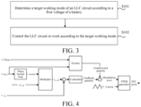
FIG. 3 is a flowchart of a charger control method according to an exemplary embodiment. -
FIG. 4 is a schematic diagram of a method for controlling a power factor correction circuit in a charger according to an exemplary embodiment. - The following describes the specific implementations of the present disclosure in detail with reference to the accompanying drawings. It should be understood that the specific implementations described herein are merely used to describe and explain the present disclosure, but are not intended to limit the present disclosure.
- The present disclosure provides a charger. The charger may be an on-board charger or a charging pile charger, and the charging pile charger and the on-board charger may adopt a same circuit topology structure (as shown in
FIG. 2 ). As shown inFIG. 1 , thecharger 100 includes a charger control apparatus 5, and a powerfactor correction circuit 2, a bus capacitor C1, and anLLC circuit 3 that are connected sequentially. The powerfactor correction circuit 2 is connected to apower grid 1, theLLC circuit 3 is configured to be connected to abattery 4, and the bus capacitor C1 may be an electrolytic capacitor, a film capacitor, a ceramic capacitor, or the like and configured to filter a direct current voltage. - The charger control apparatus 5 is connected to both the power
factor correction circuit 2 and theLLC circuit 3, and is configured to perform a charger control method applied to the charger, to control the powerfactor correction circuit 2 and theLLC circuit 3 to work, so as to charge the battery. The powerfactor correction circuit 2 is configured to perform power factor correction on an input signal of the power grid and output a current signal obtained through the power factor correction; and theLLC circuit 3 is configured to perform direct current conversion on the current signal obtained through the power factor correction, to obtain a direct current so as to charge the battery of a vehicle. - As shown in
FIG. 2 , the powerfactor correction circuit 2 may include: a third-phase bridge arm formed by a first switch tube T1 and a second switch tube T2, and a fourth-phase bridge arm formed by a third switch tube T3 and a fourth switch tube T4, where a midpoint of the third-phase bridge arm is connected to a positive electrode of thepower grid 1 through an inductor L1, and a midpoint of the fourth-phase bridge arm is connected to a negative electrode of thepower grid 1; and a third bus end of the third-phase bridge arm and the fourth-phase bridge arm is connected to an end of the bus capacitor C1, and a fourth bus end of the third-phase bridge arm and the fourth-phase bridge arm is connected to another end of the bus capacitor C1. - A current voltage on an alternating-current side of the charger is ua, a current current on the alternating-current side of the charger is ia , and a voltage between two ends of the bus capacitor C1 is Ubus (that is, a second voltage).
- As shown in
FIG. 2 , theLLC circuit 3 includes aninverter circuit 31, aresonant circuit 32, and arectifier circuit 33 that are connected sequentially. - The
inverter circuit 31 includes: a first-phase bridge arm formed by a fifth switch tube T5 and a sixth switch tube T6, and a second-phase bridge arm formed by a seventh switch tube T7 and an eighth switch tube T8, where a first bus end of the first-phase bridge arm and the second-phase bridge arm is connected to the end of the bus capacitor C1 and the third bus end, and a second bus end of the first-phase bridge arm and the second-phase bridge arm is connected to the another end of the bus capacitor C1 and the fourth bus end. - The
resonant circuit 32 adopts an LLC resonant cavity, and includes a resonant inductor L2, a resonant capacitor C2, and a transformer M1. An end of the resonant inductor L2 is connected to a midpoint of the first-phase bridge arm, and another end is connected to a first input end on a primary side of the transformer M1, where the resonant inductor L2 may be magnetically integrated with the transformer M1 to participate in resonance in the resonant circuit. An end of the resonant capacitor C2 is connected to a midpoint of the second-phase bridge arm, and another end is connected to a second input end on the primary side of the transformer M1, where the resonant capacitor C2 may be a film capacitor or a ceramic capacitor, to prevent a direct-current offset of the transformer M1 and participate in resonance in the resonant circuit. The transformer M1 may be a tapped transformer and configured for electric energy isolation transmission. - The
rectifier circuit 33 includes a fifth-phase bridge arm formed by a first diode D1 and a second diode D2, a sixth-phase bridge arm formed by a third diode D3 and a fourth diode D4, and a filter capacitor C3. A midpoint of the fifth-phase bridge arm is connected to a first input end on a secondary side of the transformer M1, and a midpoint of the sixth-phase bridge arm is connected to a second input end on the secondary side of the transformer M1. A fifth bus end of the fifth-phase bridge arm and the sixth-phase bridge arm is connected to an end of the filter capacitor C3 and the positive electrode of thebattery 4, and a sixth bus end of the fifth-phase bridge arm and the sixth-phase bridge arm is connected to another end of the filter capacitor C3 and the negative electrode of thebattery 4. The filter capacitor C3 is a capacitor on a battery side and is configured to filter a direct current voltage on the battery side. - In addition, it should be noted that, the
rectifier circuit 33 may use a switch tube device or a rectifier diode (as shown inFIG. 2 ) to implement electric energy transmission. - The following describes the charger control method applied to the charger in detail. As shown in
FIG. 3 , the method may include S301 and S302. - S301. A target working mode of an LLC circuit is determined according to a first voltage of a battery.
- In the present disclosure, the first voltage of the battery is a voltage between two ends of the battery and is a voltage on a direct-current side. The first voltage may be obtained through sampling by using a voltage sensor, or may be obtained in a vehicle packet communication manner.
- The target working mode is a full-bridge mode or a half-bridge mode.
- S302. The LLC circuit is controlled to work according to the target working mode.
- In the foregoing technical solutions, the target working mode of the LLC circuit may be determined according to the voltage of the battery, and the LLC circuit is further controlled to work according to the target working mode. The target working mode is a full-bridge mode or a half-bridge mode. Therefore, dynamic switching of the working mode of the LLC circuit can be achieved according to the voltage of the battery, avoiding generation of an uncontrollable rectified current, so that the charger works safely, stably, and reliably in various working conditions, and a control mode is simple and efficient.
- The following describes in detail a specific implementation of determining the target working mode of the LLC circuit according to the first voltage of the battery in S301.
- Specifically, if the first voltage is less than a first preset voltage, the target working mode is determined as the half-bridge mode; and if the first voltage is greater than or equal to the first preset voltage, the target working mode is determined as the full-bridge mode.
- As can be known according to a circuit principle of the circuit topology shown in
FIG. 2 , to ensure that the charger works in a safe range, it needs to be ensured that a voltage between two ends of the bus capacitor C1 (that is, the second voltage) meets

- Therefore, the first preset voltage may be set to


- When the first voltage of the battery changes from being greater than or equal to


- The following describes in detail a specific implementation of controlling the LLC circuit to work according to the target working mode in S302.
- Specifically, if the target working mode is the half-bridge mode, an upper bridge arm and a lower bridge arm of the first-phase bridge arm are controlled to turn on complementarily through a first duty cycle, and an upper bridge arm of the second-phase bridge arm is controlled to turn off and a lower bridge arm of the second-phase bridge arm is controlled to turn on; and if the target working mode is the full-bridge mode, the upper bridge arm and the lower bridge arm of the first-phase bridge arm are controlled to turn on complementarily through the first duty cycle, and the upper bridge arm and the lower bridge arm of the second-phase bridge arm are controlled to turn on complementarily through the first duty cycle, where the upper bridge arm of the first-phase bridge arm and the lower bridge arm of the second-phase bridge arm are turned on simultaneously, and the lower bridge arm of the first-phase bridge arm and the upper bridge arm of the second-phase bridge arm are turned on simultaneously.
- For example, the LLC circuit is shown in
FIG. 2 . In this case, if the target working mode is the half-bridge mode, the fifth switch tube T5 and the sixth switch tube T6 are controlled to turn on complementarily through the first duty cycle, the seventh switch tube T7 is controlled to turn off continuously, and the eighth switch tube T8 is controlled to turn on continuously; and if the target working mode is the full-bridge mode, the fifth switch tube T5 and the sixth switch tube T6 are controlled to turn on complementarily through the first duty cycle, and the seventh switch tube T7 and the eighth switch tube T8 are controlled to turn on complementarily through the first duty cycle, where the fifth switch tube T5 and the eighth switch tube T8 are turned on simultaneously, and the sixth switch tube T6 and the seventh switch tube T7 are turned on simultaneously. - In addition, according to abnormality analysis, the working mode of the LLC circuit is distinguished by using the first preset voltage as a critical point. Therefore, it can be deduced that, the voltages Ubus between the two ends of the bus capacitor C1 in the two working modes (that is, the full-bridge mode and the half-bridge mode) are greatly different, where in the half-bridge mode, Ubus=2*K*Udc, and in the full-bridge mode, Ubus=K*Udc. In this way, when the LLC circuit is switched from the half-bridge mode to the full-bridge mode, an input voltage (that is, Ubus) of the LLC circuit is excessively high, leading to generation of an extremely large current in the resonant cavity, and the charger has a risk of being damaged. For the same on time, a higher input voltage of the LLC circuit indicates a larger current flowing through the resonant circuit.
- To avoid the generation of a large current in the resonant cavity when the LLC circuit is switched from the half-bridge mode to the full-bridge mode, the following method is proposed:
- To ensure that the charger works in a safe range, it needs to be ensured that the voltage between the two ends of the bus capacitor C1 meets


- Specifically, in a case that the target working mode is the full-bridge mode, before the step that the upper bridge arm and the lower bridge arm of the first-phase bridge arm are controlled to turn on complementarily through the first duty cycle, that the LLC circuit is controlled to work according to the target working mode (S302) may further include the following steps:
- a second voltage of the bus capacitor is obtained;
- if the second voltage is less than the second preset voltage, the step that the upper bridge arm and the lower bridge arm of the first-phase bridge arm are controlled to turn on complementarily through the first duty cycle and the upper bridge arm and the lower bridge arm of the second-phase bridge arm are controlled to turn on complementarily through the first duty cycle is performed, where a ratio of the second preset voltage to the first preset voltage is equal to a turn ratio of a transformer in the resonant circuit; and
- if the second voltage is greater than or equal to the second preset voltage, the upper bridge arm and the lower bridge arm of the first-phase bridge arm are controlled to turn on complementarily through a second duty cycle, and the upper bridge arm and the lower bridge arm of the second-phase bridge arm are controlled to turn on complementarily through the second duty cycle, where the upper bridge arm of the first-phase bridge arm and the lower bridge arm of the second-phase bridge arm are turned on simultaneously, the lower bridge arm of the first-phase bridge arm and the upper bridge arm of the second-phase bridge arm are turned on simultaneously, and the second duty cycle is less than the first duty cycle. For example, the first duty cycle is 50%, and the second duty cycle is 10%.
- In the foregoing implementation, when Ubus is greater than or equal to the second preset voltage, the LLC circuit is not directly switched from the half-bridge mode to the full-bridge mode. Instead, the upper bridge arms and the lower bridge arms of the phase bridge arms in the inverter circuit are controlled to turn on complementarily through the duty cycle less than the foregoing first duty cycle, so that on duty cycles of the upper bridge arms and the lower bridge arms of the phase bridge arms in the inverter circuit are limited, that is, on time of the upper bridge arms and the lower bridge arms of the phase bridge arms in the inverter circuit is reduced. Therefore, a current in the resonant cavity is effectively suppressed, and generation of a large current in the resonant cavity when the LLC circuit is switched from the half-bridge mode to the full-bridge mode is further avoided, thereby improving the safety and stability of the charger.
- In addition, the foregoing method may further include the following step (1) to step (4):
- (1) Current electricity information of the alternating-current side of the charger and the second voltage of the bus capacitor are obtained.
- In the present disclosure, the electricity information includes a current current and a current voltage on the alternating-current side.
- For example, the current current on the alternating-current side of the charger may be obtained through a current sensor; and the current voltage on the alternating-current side of the charger and the second voltage of the bus capacitor may be obtained through a voltage sensor. In this way, the current electricity information of the alternating-current side of the charger and the second voltage of the bus capacitor may be clear, to provide a data support for current adjustment on the alternating-current side.
- (2) A steady-state target current on the alternating-current side is determined.
- In the present disclosure, the steady-state target current is a current value corresponding to the alternating-current side of the charger when the charger is in a stable and efficient optimal working state.
- (3) A target current value on the alternating-current side is determined according to the current voltage and the steady-state target current.
- For example, a phase of an alternating current outputted by the power grid may be extracted according to the current voltage ua (that is, a voltage of the current outputted by the power grid). For example, a product of the steady-state target current and the phase of the alternating current outputted by the power grid may be determined as the target current value. As shown in
FIG. 4 , if the steady-state target current is Ia_ref, and the phase of the alternating current outputted by the power grid and determined based on a phase locked loop is cos wt, Ia_ref * cos wt may be determined as the target current value I a_ref1· - (4) A power factor correction circuit is controlled to perform power factor correction according to the target current value, the current current, the current voltage, and the second voltage.
- Specifically, as shown in
FIG. 4 , the second voltage Ubus and the current voltage ua may be inputted into a divider, to obtain a feedforward quantity ua /Ubus of a closed-loop control result. The target current value I a_ref1 and the current current ia are inputted into a controller, to obtain a feedback quantity of the closed-loop control result. Then, a difference between the feedforward quantity and the feedback quantity is used as a modulation wave and transmitted to a PWM generator, to obtain a duty cycle of the power factor correction (PFC) circuit, and the current on the alternating-current side may change along with the target current value in a manner of adjusting the duty cycle of the power factor correction circuit, to implement power factor correction. - The following describes in detail a specific implementation of determining the steady-state target current on the alternating-current side in the foregoing step (2). Specifically, the step may be implemented through the following step (21) and step (22):
(21). A target charging power on the alternating-current side is determined. - In the present disclosure, the target charging power is a power on the alternating-current side of the charger when the charger is in a stable and efficient optimal working state. Specifically, a minimum value in a maximum output power of the power grid, a current output power of the power grid, a maximum charging power of the battery allowed by a battery management system, a maximum power allowed by a wire, and a maximum charging power of the charger is determined as the target charging power.
- For example, the maximum output power of the power grid and the maximum power allowed by the wire may be determined according to content in the national standard GBT 18487.1-2015; the current output power of the power grid may be determined through a power sensor arranged on the power grid in advance; the maximum charging power of the battery allowed by the battery management system may be determined according to related parameter information of the battery; and the maximum charging power of the charger may be determined according to hardware device selection of the charger, that is, belong to an inherent attribute parameter of the charger. The to-be-selected powers are respectively maximum powers corresponding to the power grid, the battery, the wire, and the charger, and the current output power of the power grid. Therefore, by selecting a minimum value as the target charging power, it may be ensured that during working of the charger, the power grid and the battery connected to the charger and wires connecting various parts are all in a safe working state, thereby reducing a possibility of a damaged electronic element on a related circuit. In addition, the power on the alternating-current side of the charger may be ensured to reach a maximum value while working safety is ensured. Therefore, if the power on the alternating-current side of the charger is the target charging power, the charger may be in the stable and efficient optimal working state.
- (22) The steady-state target current on the alternating-current side is determined according to the target charging power.
- In the present disclosure, the steady-state target current on the alternating-current side is a current value determined according to the target charging power. The steady-state target current may be determined according to a quotient of the target charging power and a valid value of an alternating-current voltage outputted by the power grid.
- In addition, the charger control apparatus 5 may include:
- a memory, having a computer program stored therein; and
- a controller, the controller, when executing the computer program, implementing the steps of the charger control method according to the present disclosure.
- The present disclosure further provides a vehicle, including a battery and the charger according to the present disclosure.
- Exemplary implementations of the present disclosure are described in detail above with reference to the accompanying drawings, but the present disclosure is not limited to the specific details in the above implementations. Various simple variations may be made to the technical solutions of the present disclosure within the scope of the technical idea of the present disclosure, and such simple variations shall all fall within the protection scope of the present disclosure.
- In addition, it should be noted that, specific technical features described in the foregoing specific implementations may be combined in any appropriate manner without conflict. To avoid unnecessary repetition, various possible combinations are not further described in the present disclosure.
- In addition, the various implementations of the present disclosure may be combined arbitrarily without departing from the idea of the present disclosure, and such combinations shall also be considered as the content disclosed in the present disclosure.
Claims (10)
- A charger control method, applied to a charger, the charger being an on-board charger or a charging pile charger, the charger comprising an LLC circuit, the LLC circuit being connected to a battery, and the method comprising:determining a target working mode of the LLC circuit according to a first voltage of the battery, wherein the target working mode is a full-bridge mode or a half-bridge mode; andcontrolling the LLC circuit to work according to the target working mode.
- The method according to claim 1, wherein determining the target working mode of the LLC circuit according to the first voltage comprises:if the first voltage is less than a first preset voltage, determining the target working mode as the half-bridge mode; andif the first voltage is greater than or equal to the first preset voltage, determining the target working mode as the full-bridge mode.
- The method according to claim 1 or 2, wherein the LLC circuit comprises an inverter circuit, a resonant circuit, and a rectifier circuit that are connected sequentially, wherein the inverter circuit comprises a first-phase bridge arm and a second-phase bridge arm; and
controlling the LLC circuit to work according to the target working mode comprises:if the target working mode is the half-bridge mode, controlling an upper bridge arm and a lower bridge arm of the first-phase bridge arm to turn on complementarily through a first duty cycle, and controlling an upper bridge arm of the second-phase bridge arm to turn off and a lower bridge arm of the second-phase bridge arm to turn on; andif the target working mode is the full-bridge mode, controlling the upper bridge arm and the lower bridge arm of the first-phase bridge arm to turn on complementarily through the first duty cycle, and controlling the upper bridge arm and the lower bridge arm of the second-phase bridge arm to turn on complementarily through the first duty cycle, wherein the upper bridge arm of the first-phase bridge arm and the lower bridge arm of the second-phase bridge arm are turned on simultaneously, and the lower bridge arm of the first-phase bridge arm and the upper bridge arm of the second-phase bridge arm are turned on simultaneously. - The method according to claim 3, wherein the charger further comprises a bus capacitor, a first bus end of the first-phase bridge arm and the second-phase bridge arm is connected to an end of the bus capacitor, and a second bus end of the first-phase bridge arm and the second-phase bridge arm is connected to another end of the bus capacitor; and
in a case that the target working mode is the full-bridge mode, before the step of controlling the upper bridge arm and the lower bridge arm of the first-phase bridge arm to turn on complementarily through the first duty cycle, controlling the LLC circuit to work according to the target working mode further comprises:obtaining a second voltage of the bus capacitor; andif the second voltage is less than a second preset voltage, performing the step of controlling the upper bridge arm and the lower bridge arm of the first-phase bridge arm to turn on complementarily through the first duty cycle, wherein a ratio of the second preset voltage to the first preset voltage is equal to a turn ratio of a transformer in the resonant circuit. - The method according to claim 4, wherein controlling the LLC circuit to work according to the target working mode further comprises:
if the second voltage is greater than or equal to the second preset voltage, controlling the upper bridge arm and the lower bridge arm of the first-phase bridge arm to turn on complementarily through a second duty cycle, and controlling the upper bridge arm and the lower bridge arm of the second-phase bridge arm to turn on complementarily through the second duty cycle, wherein the upper bridge arm of the first-phase bridge arm and the lower bridge arm of the second-phase bridge arm are turned on simultaneously, the lower bridge arm of the first-phase bridge arm and the upper bridge arm of the second-phase bridge arm are turned on simultaneously, and the second duty cycle is less than the first duty cycle. - The method according to any one of claims 1 to 5, wherein the charger further comprises a power factor correction circuit and the bus capacitor, wherein the power factor correction circuit is connected to the LLC circuit through the bus capacitor; and
the method further comprises:obtaining current electricity information of an alternating-current side of the charger and the second voltage of the bus capacitor, wherein the electricity information comprises a current current and a current voltage on the alternating-current side;determining a steady-state target current on the alternating-current side;determining a target current value on the alternating-current side according to the current voltage and the steady-state target current; andcontrolling, according to the target current value, the current current, the current voltage, and the second voltage, the power factor correction circuit to perform power factor correction. - The method according to claim 6, wherein determining the steady-state target current on the alternating-current side comprises:determining a target charging power on the alternating-current side; anddetermining the steady-state target current on the alternating-current side according to the target charging power.
- A charger control apparatus (5), comprising:a memory, having a computer program stored therein; anda controller, the controller, when executing the computer program, implementing the steps of the method according to any one of claims 1 to 7.
- A charger (100), comprising a power factor correction circuit (2), a bus capacitor (C1), and an LLC circuit (3) that are connected sequentially, and the charger (100) further comprising:
the charger control apparatus (5) according to claim 8, wherein the charger control apparatus (5) is connected to both the power factor correction circuit (2) and the LLC circuit (3). - A vehicle, comprising a battery (4) and the charger (100) according to claim 9.
Applications Claiming Priority (2)
| Application Number | Priority Date | Filing Date | Title |
|---|---|---|---|
| CN202211059072.4A CN117656896B (en) | 2022-08-30 | 2022-08-30 | Charger control method and device, charger and vehicle |
| PCT/CN2023/108248 WO2024045936A1 (en) | 2022-08-30 | 2023-07-19 | Charger control method and apparatus, charger, and vehicle |
Publications (2)
| Publication Number | Publication Date |
|---|---|
| EP4582299A1 true EP4582299A1 (en) | 2025-07-09 |
| EP4582299A4 EP4582299A4 (en) | 2026-01-21 |
Family
ID=90068737
Family Applications (1)
| Application Number | Title | Priority Date | Filing Date |
|---|---|---|---|
| EP23858972.5A Pending EP4582299A4 (en) | 2022-08-30 | 2023-07-19 | METHOD AND DEVICE FOR CONTROLLING A CHARGER, CHARGER AND VEHICLE |
Country Status (6)
| Country | Link |
|---|---|
| US (1) | US20250192684A1 (en) |
| EP (1) | EP4582299A4 (en) |
| JP (1) | JP2025528451A (en) |
| KR (1) | KR20250041039A (en) |
| CN (1) | CN117656896B (en) |
| WO (1) | WO2024045936A1 (en) |
Family Cites Families (24)
| Publication number | Priority date | Publication date | Assignee | Title |
|---|---|---|---|---|
| JP4582318B2 (en) * | 2005-02-23 | 2010-11-17 | ミツミ電機株式会社 | Resonant power supply |
| CN101312330A (en) * | 2008-05-09 | 2008-11-26 | 合肥雷科电子科技有限公司 | High voltage power source of resonant transformer |
| CN201594757U (en) * | 2009-11-30 | 2010-09-29 | 比亚迪股份有限公司 | A vehicle charging device |
| CN102570560B (en) * | 2012-01-18 | 2014-07-09 | 华北电力大学(保定) | Charging-discharging system for V2G bilateral power conversion electric automobile and control method thereof |
| CN105191099A (en) * | 2013-03-14 | 2015-12-23 | 恩菲斯能源公司 | Method and apparatus for determining a bridge mode for power conversion |
| US9263960B2 (en) * | 2013-09-16 | 2016-02-16 | Delta Electronics, Inc. | Power converters for wide input or output voltage range and control methods thereof |
| KR101529889B1 (en) * | 2015-04-10 | 2015-06-18 | 한양전공주식회사 | Switchgear capable of power factor correction |
| US9973099B2 (en) * | 2015-08-26 | 2018-05-15 | Futurewei Technologies, Inc. | AC/DC converters with wider voltage regulation range |
| JP2018148767A (en) * | 2017-03-09 | 2018-09-20 | 株式会社デンソー | Power system |
| KR102008420B1 (en) * | 2017-06-15 | 2019-08-13 | 현대자동차(주) | Apparatus for controling llc converter |
| CN107994789A (en) * | 2017-11-24 | 2018-05-04 | 浙江大学 | A kind of isolated form integrated form AC-DC converter based on non-bridge PFC and LLC resonance |
| CN108258910A (en) * | 2017-12-25 | 2018-07-06 | 浙江大学 | A kind of full-bridge LLC resonant transform circuits and its wide range output control method |
| JP6943209B2 (en) * | 2018-03-13 | 2021-09-29 | 株式会社豊田自動織機 | Power factor improving device |
| CN108427050A (en) * | 2018-03-13 | 2018-08-21 | 广东美的制冷设备有限公司 | Method for diagnosing faults, the device of power factor corrector for air conditioner |
| CN109067229B (en) * | 2018-08-24 | 2023-01-20 | 深圳市永联科技股份有限公司 | LLC resonant conversion circuit and method and device for determining working mode thereof |
| WO2020115800A1 (en) * | 2018-12-03 | 2020-06-11 | 三菱電機株式会社 | Power conversion device |
| JP7309365B2 (en) * | 2019-01-11 | 2023-07-18 | 新電元工業株式会社 | power supply |
| CN112366760A (en) * | 2019-07-25 | 2021-02-12 | Oppo广东移动通信有限公司 | Charging circuit, charging method and wireless transmitting equipment |
| JP2021044866A (en) * | 2019-09-06 | 2021-03-18 | 株式会社豊田自動織機 | Power conversion device |
| JP7368218B2 (en) * | 2019-12-16 | 2023-10-24 | ニチコン株式会社 | Bidirectional DC/DC converter circuit and power storage system |
| US12214684B2 (en) * | 2020-03-06 | 2025-02-04 | Zhejiang Hanmingbo New Energy Co., Ltd. | System and method for charging electric vehicles |
| JP2021158703A (en) * | 2020-03-25 | 2021-10-07 | 株式会社日立製作所 | Bidirectional DC-DC converter |
| CN111614267A (en) * | 2020-06-17 | 2020-09-01 | 深圳威迈斯新能源股份有限公司 | DCDC conversion circuit suitable for wide input voltage and vehicle charger |
| JP2022011981A (en) * | 2020-06-30 | 2022-01-17 | 株式会社Soken | Charging system |
-
2022
- 2022-08-30 CN CN202211059072.4A patent/CN117656896B/en active Active
-
2023
- 2023-07-19 JP JP2025512178A patent/JP2025528451A/en active Pending
- 2023-07-19 WO PCT/CN2023/108248 patent/WO2024045936A1/en not_active Ceased
- 2023-07-19 KR KR1020257006198A patent/KR20250041039A/en active Pending
- 2023-07-19 EP EP23858972.5A patent/EP4582299A4/en active Pending
-
2025
- 2025-02-20 US US19/059,109 patent/US20250192684A1/en active Pending
Also Published As
| Publication number | Publication date |
|---|---|
| CN117656896B (en) | 2025-01-14 |
| EP4582299A4 (en) | 2026-01-21 |
| WO2024045936A1 (en) | 2024-03-07 |
| KR20250041039A (en) | 2025-03-25 |
| CN117656896A (en) | 2024-03-08 |
| US20250192684A1 (en) | 2025-06-12 |
| JP2025528451A (en) | 2025-08-28 |
Similar Documents
| Publication | Publication Date | Title |
|---|---|---|
| CN107493015B (en) | A bidirectional DC converter with double transformer structure and its power control method | |
| KR101116498B1 (en) | Energy storage system | |
| CN104158400A (en) | Modularized high-pressure power supply circuit | |
| EP4195480A1 (en) | Resonant converter and method for controlling the resonant converter | |
| CN106655785A (en) | Bidirectional hybrid bridge DC-DC converter and half-cycle volt-second area balance control method | |
| CN112467998B (en) | Energy density adjustable multi-working mode plasma power supply | |
| CN108494256A (en) | A kind of the LLC resonant converter underloading voltage modulation system and modulation strategy of energy feedback | |
| EP4420229B1 (en) | A multi-mode control based series-resonant dc-dc power converter and control method | |
| CN111277145B (en) | Control device and control method of DC-DC conversion circuit | |
| CN108880268A (en) | The multi-mode control method of the semi-active bridge DC-DC converter of voltage-source type | |
| EP4622082A1 (en) | Power supply circuit and apparatus suitable for wide-range output, system and control method | |
| EP4620723A1 (en) | On-board charger and control method therefor | |
| US20250192596A1 (en) | Charger control method and apparatus, and charger and vehicle | |
| CN119836741A (en) | Method for controlling bidirectional charger | |
| CN114520598B (en) | Constant-current-constant-voltage conversion topological system and control method thereof | |
| CN117879185B (en) | A wireless power transmission system with single switch natural constant current and constant voltage output | |
| US20250192684A1 (en) | Charger control method and apparatus, charger, and vehicle | |
| EP4401279B1 (en) | Power conversion circuit and control method thereof, battery pack, and energy storage system | |
| CN220440568U (en) | Power supply circuit and power supply equipment | |
| CN115276399B (en) | Power conversion device control method and power conversion device | |
| KR102774650B1 (en) | Resonant inverter and control system of the same | |
| CN117134622A (en) | A device multiplexed cascade DC/DC converter | |
| Song et al. | Research and application on variable frequency and phase-shift control strategy of CLLLC resonant converter based on LADRC | |
| Li et al. | Design of a Wireless Power Transmission Control System Based on the Phase-Shift Variable Angle | |
| Yan et al. | A Bidirectional Constant-Power Double-sided LCC Inductive Wireless Charger with Adaptive Constant Power Optimal Efficiency Control Strategy |
Legal Events
| Date | Code | Title | Description |
|---|---|---|---|
| STAA | Information on the status of an ep patent application or granted ep patent |
Free format text: STATUS: THE INTERNATIONAL PUBLICATION HAS BEEN MADE |
|
| PUAI | Public reference made under article 153(3) epc to a published international application that has entered the european phase |
Free format text: ORIGINAL CODE: 0009012 |
|
| STAA | Information on the status of an ep patent application or granted ep patent |
Free format text: STATUS: REQUEST FOR EXAMINATION WAS MADE |
|
| 17P | Request for examination filed |
Effective date: 20250327 |
|
| AK | Designated contracting states |
Kind code of ref document: A1 Designated state(s): AL AT BE BG CH CY CZ DE DK EE ES FI FR GB GR HR HU IE IS IT LI LT LU LV MC ME MK MT NL NO PL PT RO RS SE SI SK SM TR |
|
| DAV | Request for validation of the european patent (deleted) | ||
| DAX | Request for extension of the european patent (deleted) | ||
| A4 | Supplementary search report drawn up and despatched |
Effective date: 20260102 |
|
| RIC1 | Information provided on ipc code assigned before grant |
Ipc: B60L 53/22 20190101AFI20251218BHEP Ipc: H02M 3/335 20060101ALI20251218BHEP Ipc: H02M 1/42 20070101ALI20251218BHEP |